


wefalck
-
Posts
6,652 -
Joined
-
Last visited
Content Type
Profiles
Forums
Gallery
Events
Everything posted by wefalck
-
 Just out of curiosity: what is a 'flop house'?
 -
PE parts on models.....
wefalck replied to Nirvana's topic in Metal Work, Soldering and Metal Fittings
Brass photo-etched parts are usually intended to represent something else than flat (or folded) sheet-metal parts. So I would venture the guess that in most cases they would require some surface treatment, such as chemical blackening or painting. I can't think of too many brass sheet-metal parts on a real ship. Typically, brass or bronze cast parts were used. However, in some cases PE bits may be tweaked to look like cast parts, e.g. bronze reenforcements/cladding on bollards or pin-rails and such. There is a certain 'artisanal' style of models that are mainly intended to show off the workmanship of the builder, where the materials are left unpainted. In such cases one could perhaps leave PE parts untreated, but they may require some special varnish (zapon lacquer) to prevent them from tarnishing. Otherwise, I can't really see a reason to leave PE parts untreated. Often, PE parts need to be soldered together and in an untreated state the solder tends to show up unsightly. -
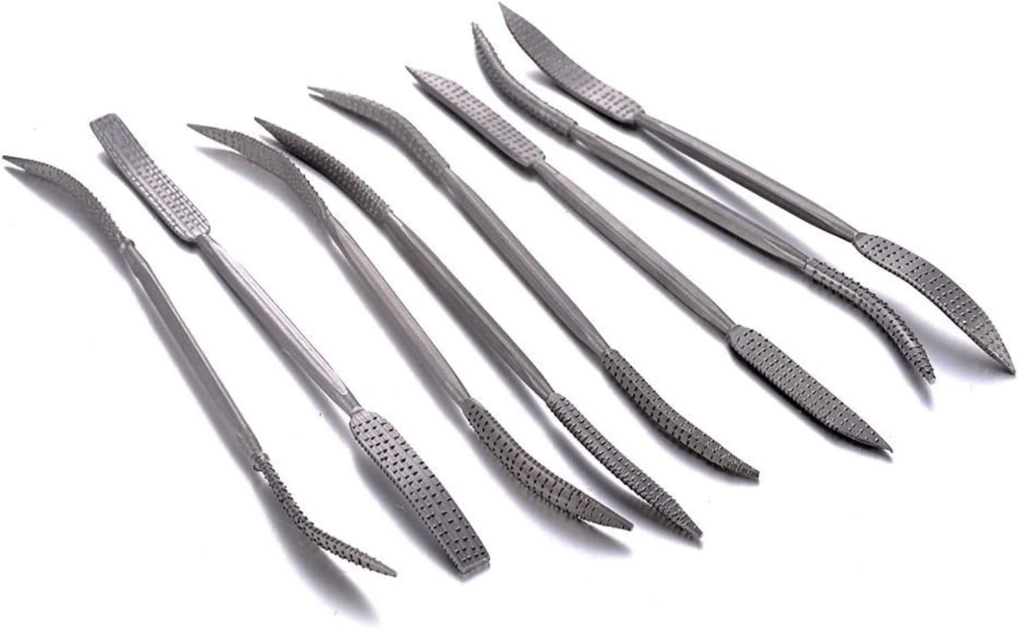
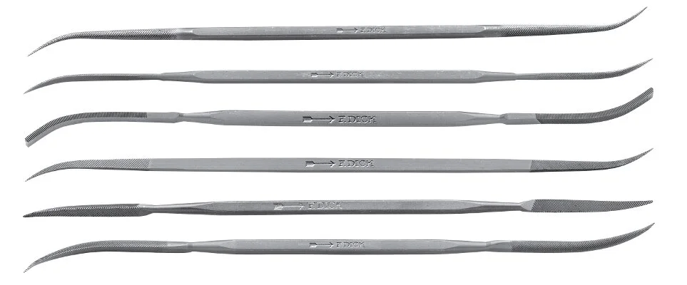
For working on concave surfaces, you may also want to consider so-called riffler files resp. rasps. Here are a couple of random example from the WWW: Rasps are intended for wood, while files are primarily intended for metal, but can also be used on wood. They come in many different shapes (and price levels).
-
Have you ever tried chemical tinning? At least over here in Europe we can buy such solutions from both, model supply and electronics supply houses. It kind of makes parts looked like steel, which they would be in real life.
- 732 replies
-
- 5
-

-

-
- Lula
- sternwheeler
- (and 1 more)
-
I think the overall impression is very good and looks 'disorderly' realistic. I agree, however, that the bunch, just before the first roband from the bottom, should be hanging down more and be less folded up and follow more gravity ... Perhaps it is helpful to do what painter would do in such a situation: they would take a broomstick and a bedcloth or something like that and make a nearly full-size prop-up to study the folds and draping.
-
... try also a fake splice on the strop with some serving using e.g. fly-tying thread. A worthwhile exercise. I don't know anything about these commercial blocks, but milling grooves for the strops would be a rather difficult and costly operation. Leaving the blocks without gives the purchaser also the option of using them for metal-stropped or internally stropped blocks. Filing a groove with a very thin (1 mm) jewellers needle file is not difficult.
-
OK, this is the notorious first planking (I wonder, why kit manufacturers still go for it, while there are better methods to create a solid foundation for the 'real' planking. However, It may have been better to begin planking prototype-fashion from the garboard up. This give you a better feeling for the run of the planking in general and how it is supposed to rund against the keel and the stem. I would consider this for the 2nd round of planking. It is also a good idea to have a look how the planking is/was done on the real thing. One of the places where traditional dhows were built until quite recently is Sur in Oman. Just 'google' with 'dhow sur oman' and lots of pictures and videos will pop up. You will have to search for images with a dhow under construction, as at completion the hull below the waterline was smeared with a concoction of quick-lime, coconut-oil and what not against the attack of Terredo navalis and you cannot see the run of the planking.
- 65 replies
-
- 3
-
-
- sultan
- Artesania Latina
- (and 2 more)
-
It doesn't need to be a structural thing. If you look carefully, not all the planks are the same width at all. Perhaps they just used what they had or the width worked out better with cut-out for the hatch - one tries to avoid to have to caulk around a notch for the hatch, when you can run the plank straight along the edge of the hatch.
- 312 replies
-
- 2
-
-
- Chile
- Latin America
- (and 6 more)
-
Standard sailmaking practice calls for the boltrope being sewn on top of the sail (usually the port side), rather than the edge. Was this also the practice for these sails? that would give a larger contact surface, than just the edge. Fabric glue might be good solution, but when the boltrope become unstuck, you can also re-attach after furling the sail at places, where it visibly has come off. Done that myself.
-
I think you painted a quite convincing picture of the history (or of the lack of knowledge about it). Relating the lancha to the botter is bizarre, as neither the shape nor the construction bears any resemblance to it. A botter doesn't have a true keel, but rather a wide bottom plank, for instance. It has been observed in other regions of the world that local boatbuilders began to adapt their types, when European tools, materials, or ways of producing half-finished goods, such as sawn lumber became available, resulting in more efficient processes, albeit at higher capital cost. Local boatbuilders may have also copied features of European craft because they were either more efficient or more 'fashionable'. Examples are the Inuit that started to use European sawn planks in their kajak construction or the Arab dhows that adopted the high square stern of the European 16th galeons once they came into contact with the Portuguese. Around the European coasts boats and small trading or fishing craft often were built be part-time builders, whose main occupation may been farming for instance. They were often built for their own use, sometimes with the advice and help of a professional boatbuilder. So it is quite conceivable that locals would put together boats basec on whatever example they may have come across.
- 312 replies
-
- 3
-
-
- Chile
- Latin America
- (and 6 more)
-
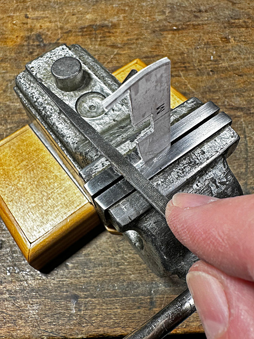
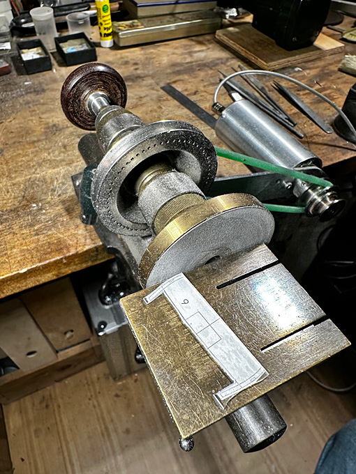
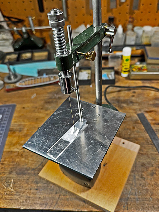
Thank you Pat ! ***************** Cutting out the bulkheads It took some time to figure out an efficient and precise way to cut out the bulkheads form the 1 mm thick acrylic glass. Unfortunately, the router table did not prove as useful as I thought, it was difficult to achieve smooth curves, as the cutter tended to bite into the material. So, I resorted to good old hand-filing. I also observed that when sawing and grinding/filing the stuck-on paper frayed and it became difficult to see the lines. Sticking the template with the printed face onto the clear acrylic glass instead the usual way solved that problem. The printed lines were protected to the end by the acrylic glass and one could work very precisely towards it. Initially, I also used a too narrow scroll-saw blade, which tended to wander. Using a slightly coarser and therefore wider blade sorted that. The process then was: cutting strips of acrylic glass just the height of the bulkheads on the circular saw; cutting out the paper templates with about a millimetre around them and sticking them onto the acrylic glass ‘face down’; the bulkhead then was roughly cut out on the scroll-saw. In the next step the part was transferred to the disc-sander and the outside of the bulkhead was shaped on it; the final step consisted of draw-filing the inside shape of the bulkhead with the part held in a small precision-vise. The bottom edge does not need any work, as the cut with the circular saw is smooth and exactly perpendicular. Rough cutting out the bulkhead on the scroll-saw Shaping the outside of the bulkhead on the disc-sander to the line Filing the inside of the bulkhead to the line in a precision-vise This process is slow and I only managed to eke out time for one bulkhead each evening between various pre-Christmas duties and more business travel. To be continued
-
I use neither, only safety goggles (with or without built-in magnification), but then I rarely use the chucks for model work, only for my tool-making. For really fine work, where you have to look at the work from different angles, face shields are impractical.
-
Nice re-purposing and probably quite in the spirit of these ships that presumably also were built with whatever was handy at the yard.
- 732 replies
-
- 6
-
-
-
- Lula
- sternwheeler
- (and 1 more)
-
I have a basic workshop safety-rule: I keep my face/head out of the line-of-flight of spinning objects as much as possible. When working with the lathe, I am always with my body slightly to the right from a spinning chuck. They also sell round polycarbonate shields for lathes, but they are not very convenient for precision work on small parts.
-
Keep in mind that the DB250 is a small wood-lathe with only 40 mm centre-height. The Sherline-chucks are designed for much heavier metal-lathes ... The spindle-thread on the DB250 should be 16x1, not sure that Sherline would offer chucks with such a thread. There may be several aftermarket options of Chinese or Indian origin for centric or independent 4-jaw chucks at moderate prices, but they typically have either 12x1 or 14x1 threads, I think. PROXXON offers a plastic independent 4-jaw-chuck, which would be quite adequate for wood-work. As long as you work from stock, the run-out of a chuck is not really important. The part in itself will be true in all its diameters. Run-out only becomes relevant, when you want to perform so-called 2nd operations, i.e. when you inverse a piece and want to work on its unmachined side. Setting up an independent 4-jaw-chuck can be a real pain and is time-consuming. You normally would need a dial-indicator to check for concentricity (there are other approximative methods). However, this can be the most precise option for 2nd operations. Not really needed for most wood-working applications.
-
Talking about machine tool safety: as far as I am aware the DB250 comes with a set of collets of up 10 mm. This is a much safer and more precise option for working on round stock up to that diameter. There is no risk that your fingers or your tool collides with the chuck jaws ... I use collets almost exclusively on my lathes.
-
Actually no. I the jaws are reversible as in almost any chuck like that. When the steps are facing inside, you can work on larger and flat items. Other chucks may be delivered with two sets of jaws instead. And: keep towels away from revolving chucks, this could result in a serious desaster otherwise. Also: never work with gloves and loose clothing on a lathe (or mill).
-
Personally, I think oil is better on scroll-chucks, as grease together with swarf may clog up the rather tight-fitting spirals. I have never used grease on my half dozen or so of different scroll-chucks.
-
Sultan Arab Dhow - Artesanía Latina - 1/60
wefalck replied to SiriusVoyager's topic in REVIEWS: Model kits
Seems to be based on one of the drawings in Pâris' Souvenirs de la Marine. It would be a good idea to cross reference with some literature, as the dhows do not use European fittings and materials. Since having been to Oman a couple of times (back in the late 1980s) and to Tanzania/Zanzibar (in 2012) I have a certain interest in ships and boats from that region. I have compiled a list of references. Those marked with an E in front are available as digital copies: E Agius, D.A., Cooper, J.P., Zazzaro, C. (2014): The Maritime Heritage of Yemen: A Focus on Traditional Wooden ‘Dhows’.- In: Agius, D.A., Gambin, T., Trakadas, A [Eds] Ships, Saints and Sealore: Cultural Heritage and Ethnography of the Mediterranean and the Red Sea: 143-157, Oxford (Archaeopress). E Agius, D.A., Cooper, J.P., Zazzaro, C., Jansen van Rensburg, J. (2014): The Dhow’s Last Redoubt? Vestiges of Wooden Boatbuilding Tradition in Yemen.- Proc. Seminar Arabian Stud., 44: 71-84. B ANONYM (1979): Oman, a Seafaring Nation.- 196 p., Sultanate of Oman (Min. of Information and Culture). ARGYLE, E.W. (1954): The Ancient Dhow.- Seabreeze, New Ser., XVIII: 262-5. LE BARON BOWEN, R. (1949): Arab Dhows of Eastern Arabia.- Rehoboth, Mass. E Carvalho, F. da Piedade (2014): Os Dhow do Zanzibar: A técnica de construção de uma antiga embarcação de origem árabe e o seu papel socioeconómico na actualidade.- Cadernos de Estudos Africanos, 27(6): 149-170. DOI: 10.4000/cea.1535. CHETHAM, M. (1950): Dhows in East Africa.- Country Life, CVIII: 1803-7. E De Leeuwe, R. (2004): Seascape and Sailing Ships of the Swahili Shores.- MA Thesis: 123 p., Leiden (University of Leiden). K De Leeuwe, R. (2005): Constructing Sailing Ships on the Swahili Shores.- Azania: Archaeological Research in Africa, 40(1): 107-113. K De Leeuwe, R. (2006): Swahili Ships in Oceanic Perspective.- Sails of History: Citizens of the Sea, ZIFF Journal No. 3: 45-52, http://www.swahiliweb.net/ziff_journal_3_files/ziff2006-07.pdf K Ennion, H. (1963): Along the Shores of the Gulf of Oman.- Country Life, CXXXIII: 1265-6. ‘FULAHIN’ (1928): Coasting East Africa by Dhow.- Blue Peter, V: 449-52. B FALCK, W.E. (2013): Boote und Bootsbau in Tansania, Teil 1: Dauen und Einbäume in Dar-es-Salaam.- Das Logbuch, 49(1): 27-30, Köln (AK Historischer Schiffbau). B FALCK, W.E. (2013): Boote und Bootsbau in Tansania, Teil 2: Bootsbau auf Sansibar.- Das Logbuch, 49(2): 62-65, Köln (AK Historischer Schiffbau). B FALCK, W.E. (2014): Boats and Boatbuilding in Tanzania (Dar-es-Salaam and Sansibar).- Int. J. Nautical Archaeology, 43(1): 162–173. GILBERT, E.O. (1997): The Zanzibar Dhow Trade. An Informal Economy on the East African Coast, 1860-1964.- PhD Dissertation: 340 p., Boston (Boston University). B HAWKINS, C.W. (1977): The Dhow – an illustrated history of the Dhow and its World.- 143 p., Lymington (Nautical Publishing Co.). HORNELL, J. (1941): The sea-going mtepe and dau of the Lamu Archipelago.- The Mariner’s Mirror, 27: 54-68. B HOWARTH, D. (1977): Dhows.- 159 p., London (Quartet Books Ltd.). E Issa, A.A. (2006): Dhows and Epidemics in the Indian Ocean Ports.- Sails of History: Citizens of the Sea, ZIFF Journal No. 3: 63-70, http://www.swahiliweb.net/ziff_journal_3_files/ ziff2006-09.pdf B JEWELL, J.H.A. (19762😞 Dhows at Mombasa.- 103 p., Nairobi (East African Publ. Ho.). B MONDFELD, W. (1979): Die Arabische Dau.- 93 p., Bielefeld (Verlag Delius, Klasing & Co.). MOORE, Sir A. (1940): Notes on Dhows.- The Mariner’s Mirror, 26(2): 205-13. SASSOON, C. (1970): The Dhows of Dar es Salaam.- Tanzania Notes and Records, 71:185-199. SHERIFF, A. (2010): Dhow Cultures of the Indian Ocean. Cosmopolitanism, Commerce and Islam.- XV+351 p. SPARKS, W. (1909/10): A Muscat Dhow.- Yachting Monthly, VIII: 263. SULIVAN, G.L. (1873): Dhow Chasing in Zanzibar Waters and on the Eastern Coast of Africa. Narrative of Five Years’ Experiences in the Suppression of the Slave Trade.- X+453 p. VILLIERS, A.J. (1940): Sons of Sindbad – An Account of Sailing with the Arabs in their Dhows.- Villiers, A.J. (1954): Passage in a Red Sea Dhow.- The Mariner’s Mirror, 40: 171-82. Villiers, A.J. (1961): Vanishing Ships – Arab Dhows.- British Petroleum Shield, 5: 6-8. VOSMER, T. (1993): The Omani Dhow Recording Project: Sultanate of Oman.- Indian Ocean Review, 6(2): 18–21, Perth. E VOSMER, T. (1997): Indigenous Fishing Craft of Oman.- Internat. J. Nautical Archaeol., 26(3): 217-235. E VOSMER, T.A., MARGARIT, R.A., TILLEY, A.F. (1992): A Survey of Traditional Vessels of the Sultanate of Oman. The Omani Dhow Recording Project. Field Reasearch 1992.- Department of Maritime Archaeology, Western Australian Maritime Museum, Report No. 69: 80 p. K WEISMANN, N. (1994): Der Beden-Safar – Eine Rekonstruktion nach Unterlagen von Admiral Pâris.- Das Logbuch, 30(3): 160-67. K WEISMANN, N. (1995): Ein Fischer-Beden in Qurm (Sultanat Oman).- Das Logbuch, 31(4): 175-82. K WEISMANN, N. (1996): Der Beden-Seyad – Ein Fischerboot des Omans im letzten Jahrhundert.- Das Logbuch, 32(4): 175-80. E WEISMANN, N. (1998): The Cargo-Beden Al-Khammam.- Internat. J. Nautical Archaeol., 27(3):237-257. E WEISMANN, N., STAPLES, E., GHIDONI, A., VOSMER, T., DZIAMSKI, P., HAAR, L. (2014): The Battīl and Zārūqah of Musandam, Oman.- Int. J. Nautical Archaeol., 43(2): 413–435. B WIEBECK, E., WINKLER, H. (2000): Segler im Monsun. Die Dau am Indischen Ozean.- 130 p., Rostock (Neuer Hochschulschriftenverlag). WISEMAN, W.F (1994): Modeling a Ninth-Century Arab Dhow.- Nautical Res. J., 40: 5-17. B YA’QUB, Y. Al-Hiji (2001): The Art of Dhow-building in Kuwait.- 164 p., London (The London Centre of Arab Studies). And an on-line resource: https://www.maritima-et-mechanika.org/maritime/tanzania/tanzania.html- 4 replies
-
- 7
-
-
-
- Kit review
- Artesania Latina
- (and 2 more)
-
The notorious on-line auction houses have 'shops' that sell scalpel blades where the'best before'-date of the sterilisation has expired so the medics can't use them anymore. Boxes of 100 tend to by quite cheap. The same 'shops' also offer heavier handles for the standard blades. Keep in mind that such scalpels are not designed for lateral forces ... These micro-scalpels look interesting, have to look for a European source ...
-
These are called 'scroll-chucks' because the bottom part of the body has a spiral milled into it in which the 'teeth' of the jaws run. Of course, swarf tends to get into the spiral and can block the jaws. It's worse with wood dust, as this soakes up the oil and forms a tough mass. Once you have taken out the jaws, you can take a toothpick and while turning the chuck you run it through the spiral inside-out, which pushes the swarf out of the spiral. Do this with each edge of the spiral, i.e. two passes.
-
Only useful for larger scales, I suppose, but jewellers also have a variety with stepped round jaws instead of tapered ones. Like for all tools YGWPF (you get what you pay for) - buying the m on-line can be a hit an miss, the jaws may not perfectly round and only rather roughly ground. Watch out for well-kept antique ones ...
-
Good luck with your shop resolutions 😉
-
Not sure what 'non-slip shelf-lining' is. Is this something you put onto the wall-brackets to preven glass-shelves from moving? I personally probably would have made myself a clamp to tie down the material to be cut, similar to what you have on those full-size miter-saws. I have such miter-box, but tend to go for high-tech solutions (lathe) in such cases 😁

