


wefalck
-
Posts
6,637 -
Joined
-
Last visited
Content Type
Profiles
Forums
Gallery
Events
Everything posted by wefalck
-
 ... I wonder, where in Italy this could be then? Only on one of the lakes in Northern Italy.
 -
Is the plane supposed to be sitting in ice? I was wondering what the white thingies on the water were ...
-
I think the ripples are too much in parallel lines. They should probably appear as shallow intersecting arches. I tend to do this in several sessions, first marking the centre of the arches and then working outwards. Also, the white foam around the posts is not in line with the calm sea. Wave would lap up to them and then be diffracted probably in form of more or less circular ripples the intersect with the other waves.
- 333 replies
-
- 10
-

-
HMCSS Victoria 1855 by BANYAN - 1:72
wefalck replied to BANYAN's topic in - Build logs for subjects built 1851 - 1900
Pat, yep, such lows in motivation happen in long-term projects. Glad to hear that you are back on it !- 1,013 replies
-
- 4
-
-
- gun dispatch vessel
- victoria
- (and 2 more)
-
HMCSS Victoria 1855 by BANYAN - 1:72
wefalck replied to BANYAN's topic in - Build logs for subjects built 1851 - 1900
Pat, I noticed a veeery long hiatus since your last post on VICTORIA. Any idea, when work will resume?- 1,013 replies
-
- 2
-
-
- gun dispatch vessel
- victoria
- (and 2 more)
-
On photographical records: archival losses due to the various wars that effected many European regions over the past 150 years are certainly an important factor. For instance, in the 1950s the current members of the most prominent ship-photographer family in Kiel (Germany), who had recorded the development of the Imperial Navy from its beginnings lived next door to my grandparents in a small apartment. Their previous apartment, like that of my grandparents, and their workshop including their archives was lost due to bombing. Decades later, I visited the last photographing family member, who was a bit older than me, in his shop and he confirmed that to me. Perhaps also there was an excitement in the USA about all these new developments and achievements and people felt that they had to documents and show it around proudly, while in Europe everyday life slowly evolved and people felt no need to document these gradual developments. Back to the project: looking forward to further developments ! A solid hull seems to me the obvious choice for this kind of ship and size of model. Gives you a solid base to attach superstructures to.
-
Edge-joined construction with dowels and mortices is a very old principle and was used over here in the Mediterranean area by the Phoenicians and the Egyptians for example. It was occassionally used also in Northern Europe for certain parts. The disadavantage is that like in clincher-planking it is virtually impossible to replace damaged planks. Are you sure the planks were only 7 mm thick (which is tad over 1/4")? That seems too thin for edge-joining. I had the feeling earlier on, you mentioned 7 cm, which is pretty massive, but could explain the absence of internal structures. For the wicker seats, you could have also glued together triangles of balsa to form a square, so that its grain runs towards the centre. Painted in some light beige, this may give a reasonable look of wicker? As this is 1:32 scale, it would call for converting some commercial figures into some 'Mariachis' or whatever bands would have played on them 😉
-
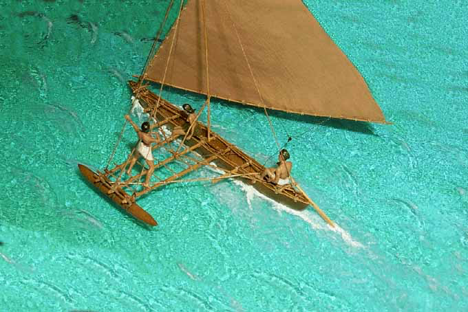
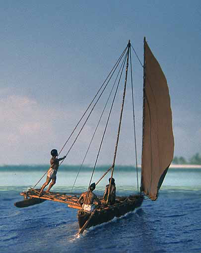
Well, that's probably the same as artists' acrylic gel, but more expensive 😁 Over the years I have used various 'substrates' for water, ranging from sculpting in plaster of Paris, sheet acrylic, layers of acrylic gel, to thick water-colour paper sealed with sanding sealer. Below is an example using blue fluorescent sheet acrylic, which is probably closest to your cast water. It tries to evoke the water in a shallow lagoon off Kiribati (Micronesia): Scale is also 1:87.
- 333 replies
-
- 10
-
-

-
I am always amazed at the number of good pre-1900 photographs available in the USA. For such subject in Europe I would struggle to find any images ... Will follow this project!
-
I would know only French or German brands that may not be available 'down-under'. I think any artists' acrylic gel will do. It is sold over here in wide-necked plastic bottles of 100 ml and above. The 100 ml lasted me a couple of decades ...
-
A colourful project indeed and good research! I am just wondering, whether these 'punts' wouldn't have had any internal structures, such as floor-timbers - or were the boards so thick that this was not needed? Without time-constraints, I personally would taken up the challenge and simulate the wicker, perhaps with thread wound around 😉
-
Unless it is suppose to be one of those leaden, dead-calm summer days, I would add some texture to the surface. I normally do this with acrylic gel, 'stippled' on with a bristle brush to simulate light wind-ripples. I also may play with some gloss acrylic varnish in places to show calmer areas. Similarly, the acrylic gel can be used to simulate some small waves lapping up the beach.
- 333 replies
-
- 11
-
-
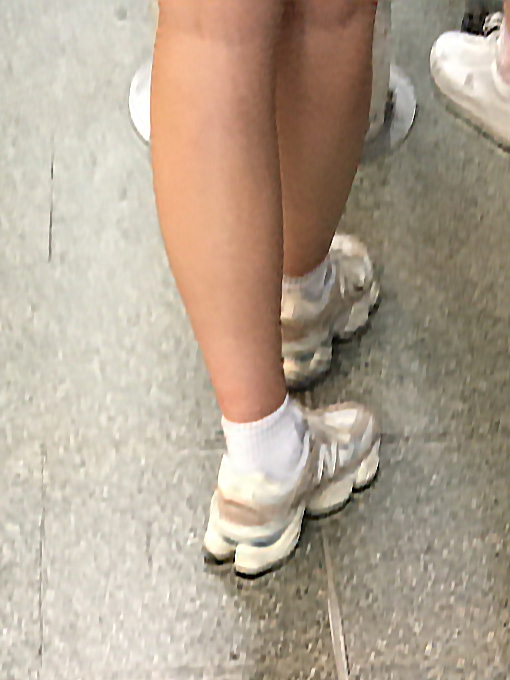
I am wondering, what footprints this girl tries to hide: Photographed last Sunday in St. Pancras station, London.
- 227 replies
-
- 12
-

-
-
From late 1977 on for several years I was on the committee that organised the annual university ball of the ETH Zurich - a 'business' with a turnover of several million Swiss Francs and organised accordingly, but by students only. That first year I joined, the theme was 'Goldrush'. Various halls, gyms etc. were decorated in theatre-like decorations that took a good part of the winter-term to prepare and build. In one hall my colleagues put up some veritable rail-tracks and constructed a working draisine on which visitors could move forwards and backwards a few metres. Unlike the rest of the decoration, the draisine was not scrapped after the ball, but we were able to store it in our workshop for further use ... sometimes we would take it out at night for rides on the local tram network through the city after the end of service. We got stopped by police, but they couldn't say anything, as it was not a motorised vehicle and didn't need a license ... 😇
-
Ahh, a flying boat has been on my list for a long time, but I was rather thinking of one of the earlier Dorniers, but that would be scratchbuilding, as no kits are available. What engine used the Macchi? I took some pictures of Italian aero-engines in the technical museum in Milan a few weeks ago. I am not so familiar with the market, but there seems to be a lot of after-market stuff around for WW1 aircraft. However, I have the feeling that it is mainly for the 1/48 and 1/32 scales. There seem to turnbuckles and lugs in etched brass available.
-
The problem is that, if kids don't learn risk awareness at an early age, it will hit the adult even harder and potentially fatally ... you should learn respect of moving things at an early age.
-
I gather the design of the model followed the full-scale industrial design practice - there, all parts would have been machined in special jigs and the tolerances would be a factor 10 less stringent probably. The design is a bit overconstrained for individual machining, because you have to hit the feed-nut at the right place and the right angle. On my watchmakers lathes, which would be of similar size, but with very close tolerances, the round feed-nuts are floating in a close-tolerance bore. This gives you two degrees of freedom: for vertical float and angular misalignment. They are also slit, allowing them to be tightened for compensating wear. Most of this is, of course, not relevant on a model.
-
They existed still in the late 1950s and I don't remember any brakes. When you hold the rocker arm tight the rear driving wheels are blocked. Of course, it would be so clever to use this downhill ...
-
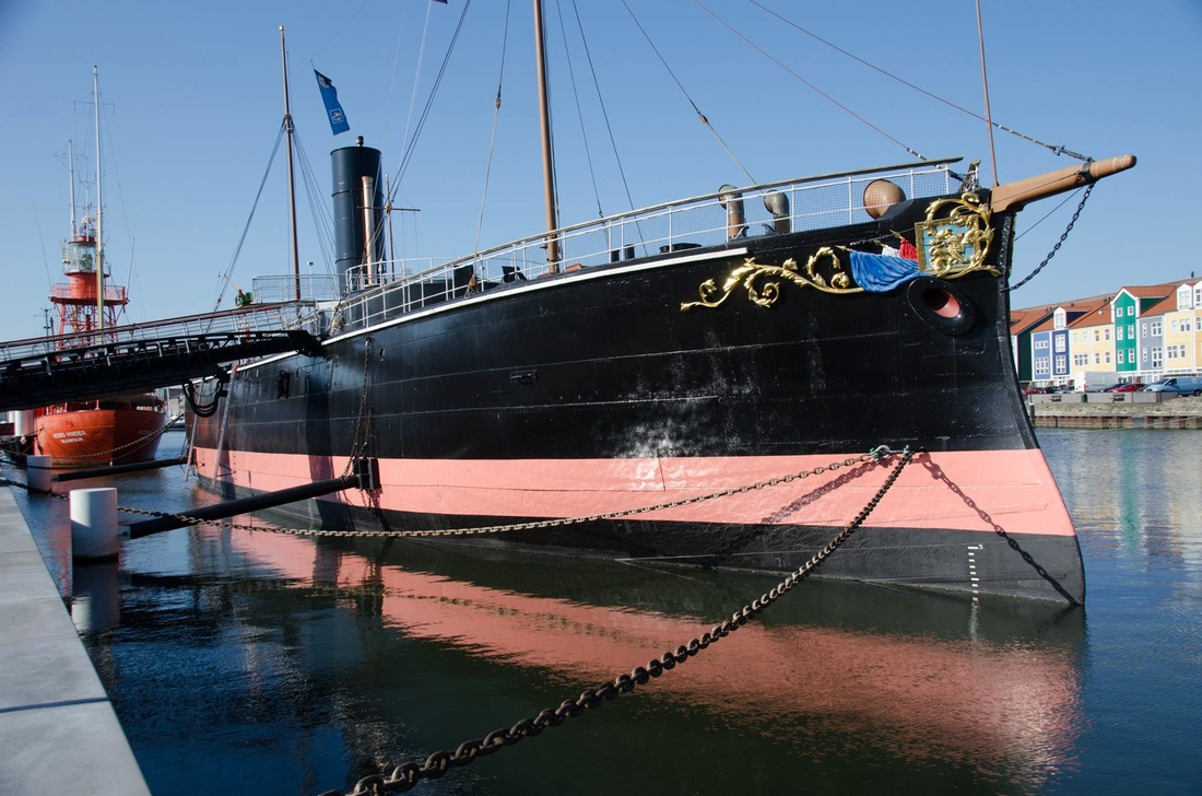
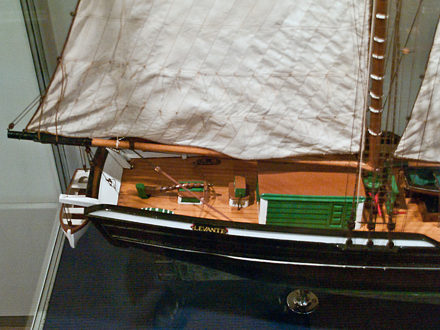
Love those Victorian-era warships, black-white-buff and still a lot of varnished wood and polished brass, much like the passenger steamers of the time. And indeed, they often had fanciful skylights and such. The ventilators seem to have a rather peculiar shape. As to the position of ventilators: the really big ones are probably providing the draft for the boilers, smaller ones would be associated with living quarters and places like that. The Dutch still have a couple of those monitor-like ships afloat, the BUFFLE and the SKORPIOEN, which may provide good pictorial reference for certain period details. BUFFEL: https://debuffel.nl From: https://onzemarinevloot.weebly.com/hrms-buffel.html SCHORPIOEN: https://nl.wikipedia.org/wiki/Zr.Ms._Schorpioen_(1868) From: my photograph
-
Tiller tackle
wefalck replied to Dr PR's topic in Discussion for a Ship's Deck Furniture, Guns, boats and other Fittings
Phil, your question made me think and that is how ideas, discussions and eventually insights develop ... -
Elementary school clear glue?
wefalck replied to modeller_masa's topic in Modeling tools and Workshop Equipment
When it smells, than it is good and works 🤪 My father was a chemist (and I am a half-chemist too) and he taught me early on respect for chemicals, but not to have fear ... -
Tiller tackle
wefalck replied to Dr PR's topic in Discussion for a Ship's Deck Furniture, Guns, boats and other Fittings
This is a common problem with amateur historians, they collect large amounts of knowledge from which they quote, but then are not able (or willing) to give proper references ... It will be near impossible to prove a date, when steering wheels were introduced, but one may be able to pin down a period, when the whipstaff definitely disappeared. One should dive into the reserve collections of the various maritime museums. They usually have functional models for innovations that were proposed to the Admiralty or to the (predecessors of) patent offices. The wedging device on the tiller of LADY WASHINGTON could be a case like that. I have not seen that before - that's why an open rope and a pin or something to belay the rope was used. -
Tiller tackle
wefalck replied to Dr PR's topic in Discussion for a Ship's Deck Furniture, Guns, boats and other Fittings
It may be indeed very difficult to put a date on such arrangements - unless one chances upon an illustration from the period in question. My guess is that not many such illustrations taken on board a ship would be available from before the early 19th century. Van de Velde jr. might be an exception, but I don't recall immediately any on-board drawings by him. As can be seen on the models quoted and many other ship models (e.g. Dutch models), it was common to have a pin or knob at the end of the tiller, which served as belaying point or brake for the tiller ropes. Actually, the arrangement with a drum and steering-wheel on the tiller may be a quite old one. It was used on the 'steert' (i.e. the tail) of Dutch windmills for centuries - a rope was stretched between two of a circle of bollards let into the ground for that purpose; the rope was wound around a drum that was worked with a wheel that looked like a ship's steering-wheel; the purpose was similar to that of a ship's tiller, to turn the mill (or its cap) into the wind using the mechanical advantage of the system. I think some mills also used tackles for the same purpose. It is difficult to know, whether this idea was adopted from ships or the other way around. Using spoked wheels to turn winding drums was also common on water-wells. I would assume that this was a technological principle that had been around for centuries. -
Tiller tackle
wefalck replied to Dr PR's topic in Discussion for a Ship's Deck Furniture, Guns, boats and other Fittings
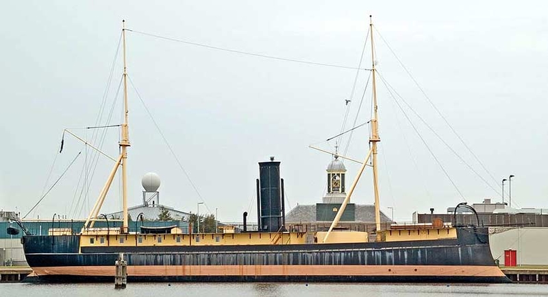
When I took my first sailing lessons in 1971 or so, I was told to use the loose end of the main sheet in case of need to steady the tiller. I gather there are many variants of this depending on the size of the vessel. Tiller-steering was also very common even for comparatively large ships, i.e. smacks, (small) schooners etc. The steering wheel and related gear was an extra expenditure. One must assume that some form of steadying the tiller was employed. Depending on the size this could be single rope from the windward side, two ropes from each side wound around the tiller, or a more elaborate arrangement, as described above. In some regions of Europe, e.g. the Dutch/German North Sea coast also steering wheels mounted on the tiller were used in the 18th and early 19th century. The problem is indeed, that this falls under the category of 'running rigging' and is seldom documented on technical drawings. Below is an example of tiller-mounted steering wheel from a model of a snow-brig of 1839 in the Altona Museum (Hamburg). It is one of a series of models that were built in the early 20th century by shipwrights from drawings and other sources in the museum: And an example of the double tackle on the model of a schooner from 1846: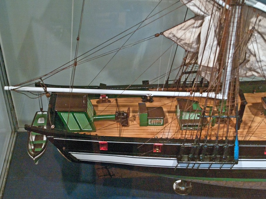
-
We all have other project and life in general slowing us down with particular projects ... looking forward to further updates along the road.
