


wefalck
-
Posts
6,668 -
Joined
-
Last visited
Content Type
Profiles
Forums
Gallery
Events
Everything posted by wefalck
-
 I know of this technique, one puts the masking tape, where the inside strakes will be and the fills the space in between to represent the outside strakes. I have never used the technique myself, but would be concerned about the edges of these 'strakes' - they could be quite vulnerable to damage such as chipping. These automotive putty do not have a lot of cohesive strength in order to allow for easy sanding and in their intended application, there would be no exposed edges.
 -
Naive question: what are 'roller boxes' ? A fixed steady with rollers (a lot of people nowadays use roller bearings for this)?
-
I am wondering, whether it wouldn't be worthwhile trying to develop a lines plans with more stations for frames from the rudimentary one that you have. It is really not too difficult and can be done basically with a ruler, a compass and a flexible batten or one of those pliable rulers (that have a lead-core). I think it will safe you a lot of frustration. If you don't have a big enough drawing board, it can be done at half the size or so and then upscaled. I am sure that it will give satisfactory results more quickly and with less materials wastage than the trial-and-error method.
-
At least there should have been a shut-off valve just after the T-junction. Having the gas-pressure on the hose is not a good idea at all ☠️ ... and nothing to prevent the flame from going back into the hose 🫣
-
It appears the German National Archives/Military Archives have a copy of a draft of 1913: https://www.archivportal-d.de/item/WEHKZZSMAUE3JZGYZHVH4HNR33ZNBEON?lang=en As well as a copy of the 1911 version: https://www.archivportal-d.de/item/QZXZLRGQESUACWL5IDGVTJYGXRXXYPYN An overview over the different German siganl codes since 1800 is given in this (German only) publication, for which an overview is available in PDF: https://dmkn.de/wp-content/uploads/2014/10/Signalflaggen.pdf I didn't see (so far) any digital copy of the code-books themselves. P.S. The code-book in the British National Archives presumably is the one offered to the British on 31 October 1914. It was found on board of SMS MAGDEBURG which ran aground at the coast of Estland. The crew attempted to blow her up, but were only partially successful. Two code-books were found on her, after the remaining crew were taken POW, and a third one that was thrown overboard with some lead attached to it was recovered by Russian divers. These code-books allowed to the Russians and the Western Allies to read the naval communication throughout WWI I think - the loss of the code-books must not have been reported properly to the Admiralty, as all the officers were taken POW (Source: https://de.wikipedia.org/wiki/SMS_Magdeburg_(1911)).
-
These whaling boats were sort of consumables in fact. They were built in early versions of production lines by specialised builders in New England. They were very lightly built boats to make the easy to row and manoeuvre, but also to create as little waves and noise so as not to startle the whales when approaching them. This made them quite vulnerable to physical damage and the whaling-ships always carried a couple of spare boats and material to repair them. As in the old days, tools typically were the property of the workers themselves, a system that made sure that they cared for them and kept them in a good working order. However, harpoons were also a sort of consumable, because they could easily bend or break in use. Lances less so. The ship would carry a good supply of spares including shafts, as the commercial success of the voyage would depend on their availability. There was also a smithy and a smith on board to help maintain and repair these tools.
-
Good (hard)wood is only to some degree a renewable resource - it takes obviously centuries to replenish it not just decades ... we have taken out too much over the past two or three centuries.
-
Interesting project and nice rendering of the boats! In summer 2019 I took quite a few pictures of her in the museum in Oslo, focusing on various details. If you need them, I could email them to you. One has to ignore the strange colours, as the museum guys chose to dramatice the exhibition with variously coloured lights 🤨
-
The method to be used surely also depends on the size of your model spar/mast. Planing something only of a few millimetres in diameter may be physically difficult. I gather a starting dimension of 4 mm across would be about the minimum for planing. Starting with a square stick allows for easy 'indexing' during work. People use a jig in which the stick rests on a corner so that one work down the opposite corner. This leads you quickly to an octogon. Resting the stick now on the corners of the octogon allows you to work it down quickly to a 16-sided stick (hexakaidecagonal stick). Turning long, slender pieces requires a steady to remove flexing. Travelling steady are difficult to use on wood, because they may leave marks, but a fixed steady is easy to contrive for a wood-lathe. In fact a thick piece of cardboard with an appropriate sized hole in it will be sufficient and was often used by old-time machinists. Old lathes did have sometimes a steady to which such cardboard pieces could be clamped. In fact, I have used the flexing in order to produce spars that taper in both directions.
-
I gather, the classic source on whaleboats is ANSEL, W.D. (1983): The Whaleboat.- 147 p., Mystic, Co. (Mystic Seaport Museum Inc.). It has plenty of drawings based on examples in Mystic and on original drawings. If you are building a whaler, this book probably is a must. The ready-made models are probably not based on whaleboats as used in whaling (which were of very light construction), but on the naval boat-type called whaler, which is a double-ended, quite sturdy boat, that was used mainly as a surf-boat, i.e. for accessing coasts without harbours and a strong surf.
-
The company was called C.C. Egelhaaf & Sohn, located in Aalen (Baden-Württemberg). The yarn size is Nm 300/2, which means that from 1 g of material 300 m of a two-ply yarn was made.
-
Interestingly, those silk-wrapped (stranded) wires are available again commercially, as there seems to be a fashion for non-IC and legacy electronics. I also inherited a small stock from my father, who was very much into electronics/electrics. Otherwise, ebay et al. now make accessing such fancy materials much easier than before, when you had to rely on local shops. I have a large collection of wires from different materials from about 0.008 mm diameter upwards. Not everything turned out to be really useful though. One thing I really regret our those threads that were used to mend ladies' nylons. One type is still available, but this is multistranded and fuzzy. This nice, two-stranded tightly twisted stuff is nowhere to be had anymore and the manufacturer in Germany that I knew is defunct. I used to scan fleamarkets for them, but was never lucky in that respect.
-
Thanks, gentlemen, for your kind comments! @Keith Black: I decided on 'hearts' and lashings, as this is what the photograph seems to show for the fore-stays. Not very clear though. Bottle-screws would be longer and thinner. @KeithAug: Caught me red-handed ... yes, the stays and shrouds - unfortunately - are not completely straight. This due to the fact that I used wire and that the anchoring is not that strong. I have used such wires in the past, but could tighten them more and it worked very well. Have to rethink that in the future and perhaps build a serving machine that can handle really thin materials. Also, the only material I had that was thin enough was solid wire, stranded wire would have been better for that purpose.
-
Why would you want them as a pair? AFRICAN QUEEN is purely fictional anyway - see HMS MIMI by Ras Ambrioso ...
-
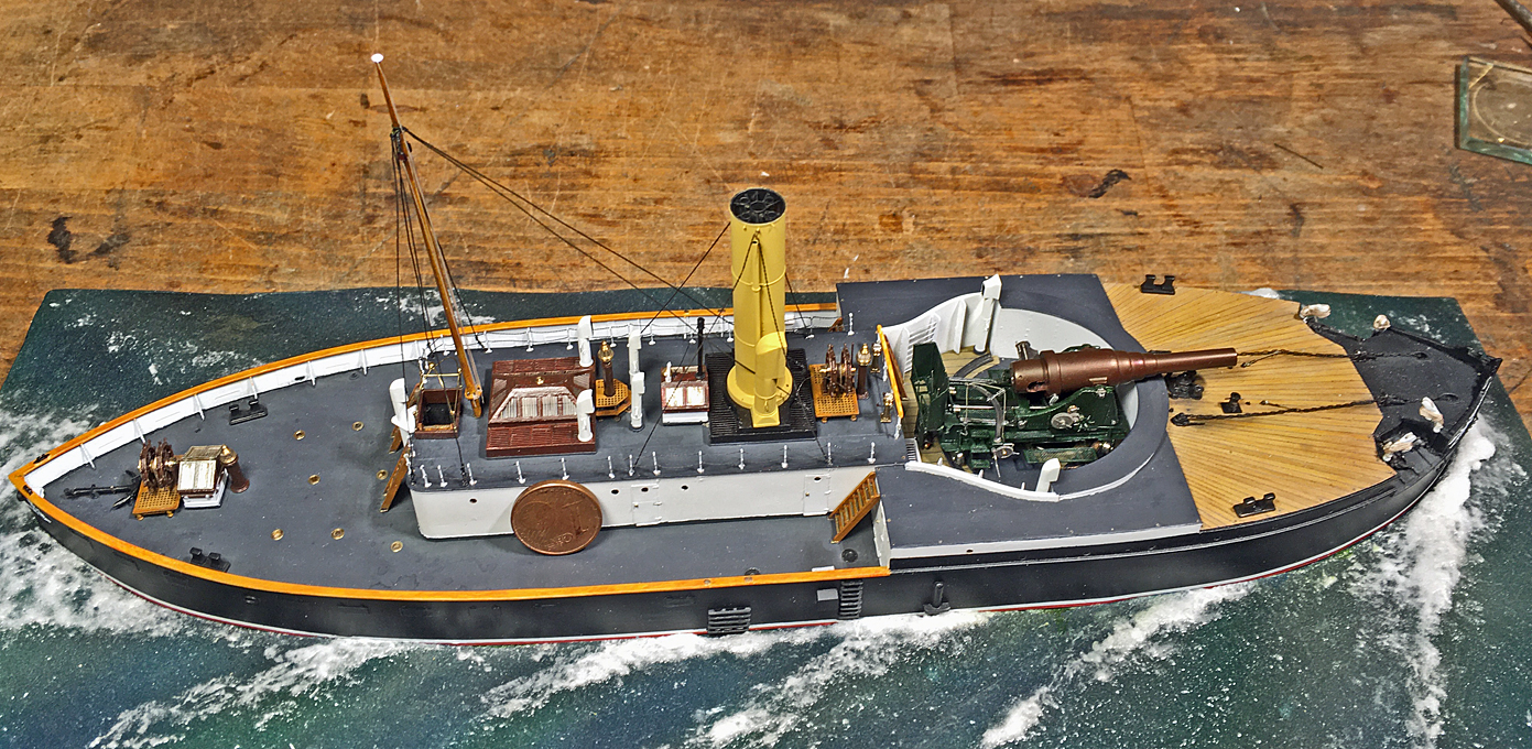
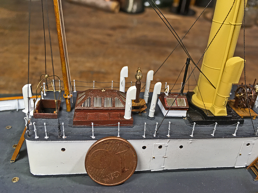
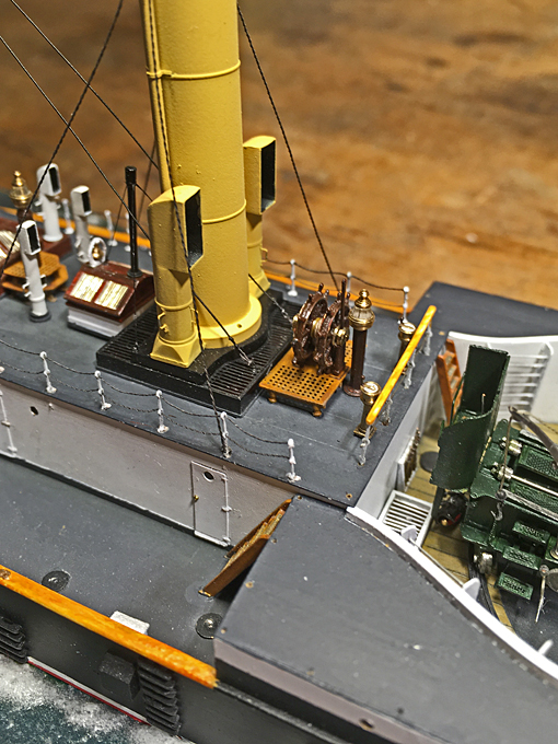
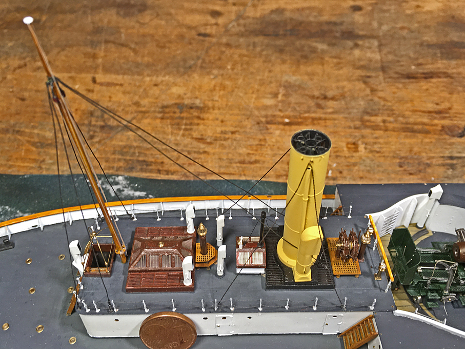
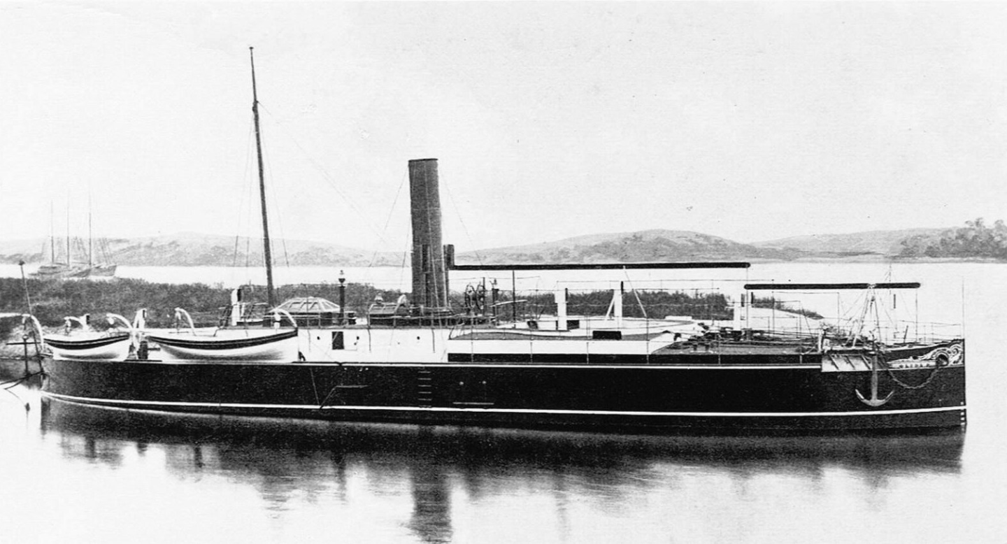
Thanks again for all the encouragement! ***************************************** Rails continued … I have installed the rails around the deck-house on the starboard-side too. This time a picture with a coin for size reference. In the meantime, a forum colleague made the suggestion to braid the wires instead of double-twisting them. I think I had tried this earlier on, but the copper-wires were too soft and broke to easily. I’ll give it a try again with the Konstantan wire and will report. They used chain on this boat for a lot of things, where today one would find wire-rope instead. Mast and rigging As noted above, my intention was to work ‘inside-out’ when installing the rails, so as not to damage already installed parts. I now realised that I should have installed also the mast and its stays first, before the deckhouse rails. So, it was high time to do it now, before going on with more rails. The pictorial evidence is rather scarce for the early form of the mast. In fact, there is only the very first photograph that shows SMS WESPE being fitted out. All other photographs show later forms, when the mast had acquired a top-mast and a fixed signalling yard. When this was installed is not known. Perhaps around the time of the first minor refit, when the boat-racks were installed, or when she got the conning tower with the search-light on top, as shown by the only other photograph with the black/white/yellow livery (as per 1878 regulations). The mast had been turned a while ago from a steel rod and fitted with belaying pins. Not sure, whether I showed already pictures of this. It seems that there were double stays leading forward to the front of the boiler-casing, but there are no pictures that show how they were fastened and the drawings are silent on this detail. So, I assumed that there must have been ring-bolts rivetted to the casing. In fact, I should have installed this before painting and installing the casing, but did not have sufficient foresight. Hence, they had to be ‘retro-fitted’ now. Then there is a pair of shrouds on each side – quite a few for a simple pole mast. These shrouds seem to have been made fast on eye-bolts between the rail-stanchions on the deck-house, for which there is a vague indication on the drawings. Again, there is no evidence for how they were set tight. I gather it must have been some hearts with lanyards between them. I assume that the stays and shrouds were wire-rope. On some later picture it vaguely looks, as if these ropes had been served all over. To imitate such ropes, I have collected over the years electronic copper wires and stranded wires and are spun with silk (as used in high-frequency coils). I choose a 0.15 mm wire for the purpose here. The silk in my case was green, so it had to be given a light coat of black paint first. Before the shrouds and the stay could go on, the signal halyard blocks had to be installed. I assumed that these were stropped double-blocks, but this is purely conjectural, based on the number of belaying pins. For the signal halyards I used some of my treasured nylon-thread as used in the old days for mending ladies’ stockings – a tightly spun two-ply thread that does seem to be out of production now (better than the fly-tying threads). The lay still was not tight enough, so I twisted it a bit more and stabilised the twist with a light touch of varnish. At that time a steamer should have carried a steamer-light at the mast at night, but the available photographs are not are not clear enough to be sure that it would have been hoisted from a halyard in front of the mast. I just installed the halyard without attempting to model any additional arrangements, such as guiding ropes. The lithograph from the early 1880s also shows a crane for light just in front of the casemate, but it is not visible on the photographs. Making working hearts for the stays would have been asking a bit too much, so I simplified the arrangements and just provided seized eyes at the end of the standing rigging and roved the lanyards through them and directly through the eyebolts. I gather this is good enough at this small scale. It was difficult enough to install all this without destroying other things already put into place. To be continued ....
- 935 replies
-
- 21
-

-

-
Ein think it just poor design - or they had certain design constraints we don't know that led to this poor design. If the saddle had been a tad longer - and the table in consequence perhaps wider, the counterbore for the saddle feed-nut could have been free at the bottom of the dovetail. I have taken apart a number of antique machines of that age and they are normally designed so that you can take out the feedscrews and -nuts for maintenance or replacement without having to take apart the whole machine. The (bronze) nut are subject to wear and need cleaning and replacement from time to time. In this case you don't want to upset the whole alignment of the table-dovetail. Anyway, as was noted before, this is only a model and once completed, no one will worry about this anymore.
-
US 6” gun by RGL - FINISHED - Panzer Concepts
wefalck replied to RGL's topic in Non-ship/categorised builds
Nice work indeed. I just wondered, whether this rather yellow camouflage wouldn't stick out like a canary in the greenish-brownish landscape of France (unless it were autumn). May be the dust is a bit too yellowish for Eastern France? -
I am somewhat surprised, that the second dovetail on the saddle was made from a separate piece of steel. I would have expected this to be machined on both side in one set-up to ensure parallelism. Or was to have the bearing surface in steel, rather than aluminium?
-
Thanks, but I am still wondering, what this 'Syrenite' is chemically 😉
-
I can very well imagine stropping such small blocks. They would be neded in that size for my next project. When you say that "they are the same material as used for 3D-printing", what does that actually mean? There are many different materials used for the different 3D-printing technologies. Talking about brown blocks and dead-eyes: have you ever tried to use phenolic resin, for instance Pertinax, as used in electric/electronic circuit boards etc.? It comes in different thicknesses and different shades of brown. It machines well and is easy to polish to nice sheen. The only draw-back is that the fumes from laser-machining are not particularly healthy.
-
Well, just scrolled through the entire retrospective log - truly impressive 👍
-
The longitudinal batten were notched into the transversal frames of the grating - I gather this is something difficult to reproduce by laser-cutting?
-
US 6” gun by RGL - FINISHED - Panzer Concepts
wefalck replied to RGL's topic in Non-ship/categorised builds
A lot of masking, I suppose, or painting with a brush? -
Indeed, that's her. The picture came from my own collection: https://www.maritima-et-mechanika.org/maritime/lisboa/Fragata-Fernando.html. I was too lazy to spell out her rather longish name
-
I may have to try this as my eyes are getting older. However, so far I found it somewhat confusing that the light moves, when I move the head. On the other hand, I have always difficulties directing the light from the direction of view ...


