


wefalck
-
Posts
6,668 -
Joined
-
Last visited
Content Type
Profiles
Forums
Gallery
Events
Everything posted by wefalck
-

Shot Garlands
wefalck replied to tmj's topic in Discussion for a Ship's Deck Furniture, Guns, boats and other Fittings
Deviating a bit from the actual subject: The method shown on the last illustration for the 19th century seems to be rather unusal and I wonder, where the author got this from. All my 19th century (European) textbooks show the waterway sitting flat on the beams and not overlapping anything. The arrangements may vary a great deal in detail, also depending on the size of the vessel and whether naval or commercial. The arrangement on this last illustration would be difficult to caulk satisfactorily, just at a place that would be one of the wettest one on a deck. -
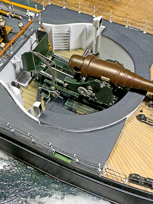
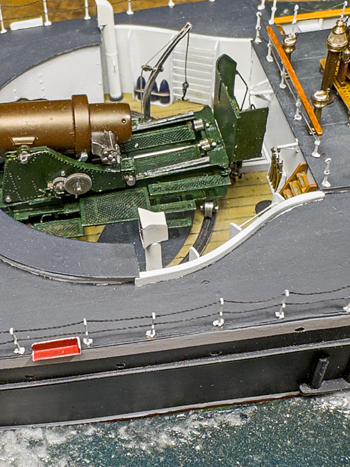
As usual, your encouraging comments are much appreciated ! ******** In the meantime, I had to make myself a list of all those tiny details that still need to be fabricated and installed. It is easy to forget them, when you are getting closer to the end … Crane above the projectile hatch Projectiles and powder bags were stored in different compartments for safety reasons below the barbette and in consequence, each had its own hatch. That for the powder bags was round, while the one for the projectiles was rectangular in order for them to lifted out on a trolley. As discussed in a much earlier post, the lithographies from the early 1880s do not show any mechanical device to help the 330 kg heavy projectiles from their storage space to the floor of the barbette. Man-handling clearly is out of question. However, drawings related to a later re-fit show inside the deckhouse a winch marked as ‘winch for the hoisting of projectiles’ and a simple derrick-like wall-crane bolted to the rear wall of the barbette. In these drawings it is not shown how the runner rope would have been led from the crane to the winch, there most have been some sort of opening in the rear of the barbette. Also, not clear is, how the in the gun-crew in the barbette and the men in the projectile storage room would have communicated with the winch-men inside the deckhouse. Interestingly, in the same drawing a simple wall-mounted crane for the powder-bags seems to be indicated, but no winch belonging to it. Perhaps the 45 kg bags were hoisted up with the help of a tackle. The assembled and painted parts at their place, port view The small detail (about 3 mm by 3 mm) of the projectile crane caused me a lot of aggravation and took a long time to fabricate. I drew it in several versions to be cut from Canson-paper on the laser-cutter until I arrived at a solution that worked. Assembly was also rather difficult and several parts jumped into the invisible black hole on the workbench, so that they had to be replaced. The pulley was turned from 1 mm steel rod. The hook was fashioned from tinned copper-wire and the shape built up from Vallejo acrylic paint ‘oily steel’. A short piece of rope was spliced into the ring and the spherical weight built up from acrylic paint. Likewise, the powder-crane was cut from two layers of Canson-paper, soaked in varnish and painted. There is no information on what it may have looked like. I did not model the tackle, assuming that during the gun-drill in which the model will be presented, no charges were used and therefore, the tackle was not rigged. Only a shackle was fashioned from tinned copper wire. Lamp-boards Another small item on my to-do-list were the lamp-boards. According to the very first photograph of SMS WESPE these were placed at the front end of the deckhouse surrounding the barbette. In the lithograph and in later photographs they are shown on short poles towards the rear end of the deckhouse and raised above the rails. These lamp-boards were laser-cut in three parts from Canson-paper and painted appropriately after assembly. The petroleum-lamps are not shown, as during day-time they would have been cleaned and then stored in deckhouse(?). The assembled and painted parts at their place, starbord view Not much to show actually for the amount time and effort spent on the parts … To be continued ....
- 935 replies
-
- 23
-

-

-
And some pretty solid equipment in the workshop 👍🏻
-
No, the saw were only sold through 'connections' it seems. I forgot the name of the guy.
-
There used to be a guy in Germany, who made small batches of very solid and precise small table saws, but as always, he was a pensioner and at some stage had to give up this business. The market is small and the costs are high, so one can really do this only, when margins can be small because you have other income
-
Pin Vise vs. Hand Vise?
wefalck replied to Balclutha75's topic in Modeling tools and Workshop Equipment
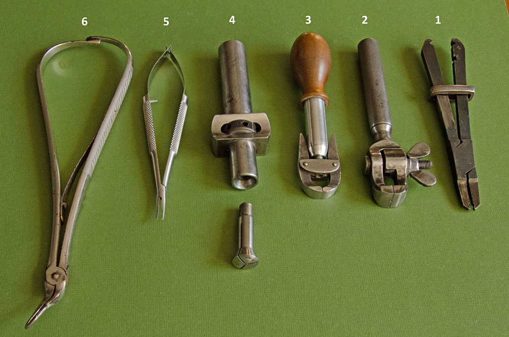
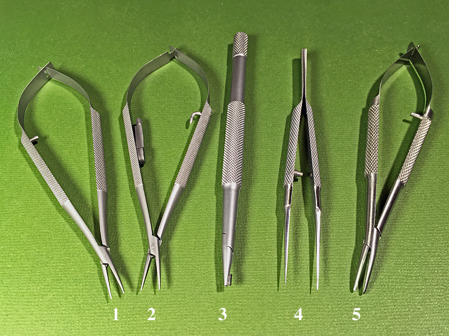
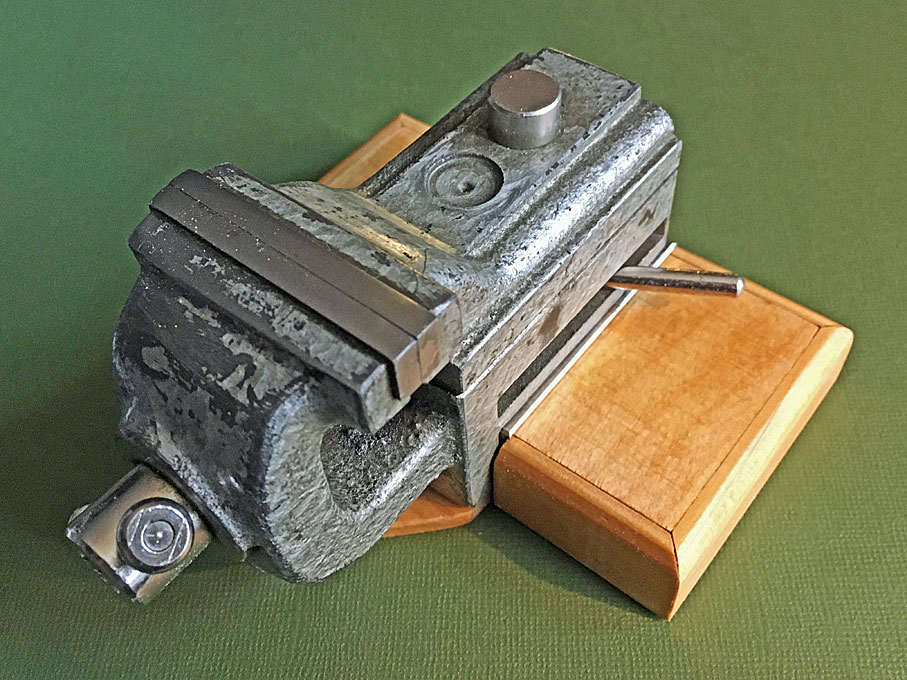
There are umpteen different types of pin- and hand-vises from different professions ranging from watchmakers, toolmakers to biologists and the medical professions. Some of them are meant mainly for tool-holding, while other are primarily for work-holding. A while ago, I put together a couple of pictures of the different types of work- and tool-holding devices that I have in my workshop (see also https://www.maritima-et-mechanika.org/tools/workholding/workholding.html). : 1 - Archimedes drill for watchmakers. 2 - Slender modern pin-vice with hollow fluted brass body. 3 - Slender antique pin-vice with hollow fluted brass body. 4 - Shop-made pin-vice with walnut body and head made from an insert drill-chuck; these drill-chucks are unfit for their intended purpose as they usually do not run true. 5 - Eclipse toolmaker's pin-vice with knurled steel body; these come in different sizes. 6 - French-style pin-vice; these are closed with the sliding ring and have usually brass inserts in the two jaws that can be adapted to special needs; 7 - Dito, here the jaws are replaced in hard-wood for delicate parts. 8 - Antique laboratory pin-vice with fluted wooden handle. 9 - Modern pin-vice with fluted wooden handle; these come in different sizes and capacities. 10 - Antique toolmaker's pin-vice for very delicate work in confined spaces. 1 - Toolmaker's hand-held vice that is closed with a sliding ring. 2 - Hand-vice with parallel serrated jaws moved by a screw. 3 - Antique american style hand-vice; the jaws are closed by screwing in the conical body; the handle and body have been replaced. 4 - Hand-held collet-holder; this uses horological lathe collets; the advantage is that work can be transferred between the holder and the lathe when it has the nominal collet diameter. 5 - Castrovejo surgical non-locking needle-holder; they come in various sizes, this has medium tips for eye-surgery. 6 - Antique surgical locking needle-holder; these come in a wide variety of sizes and shapes. A selection of Castrovejo eye-surgery tools: 1 - fine-pointed non-locking needle-holder with straight smooth tips 2 - fine-pointed locking needle-holder with smooth tips 3 - fine-pointed blade-breaker - this are used to break off pieces from razor-blades to be used a very sharp scalpels 4 - very fine-pointed tweezers - they are stiffer and less springy than the typical watchmakers or biological tweezers 5 - medium-pointed non-locking needle-holder with curved smooth tips And finally a small precision bench-vise with 30 mm jaws that I mounted on a wooden stand so that it can be shovelled around the workbench. There used to cast-iron bases for these, but they are extremely rare: Most of these tools are 'antiques', but some are still available new. Interestingly, different countries seem to prefer different types of tools. For instance nos. 6 and 7 in the first picture I have only seen in France, while no. 3 in the second picture is an US American tool type.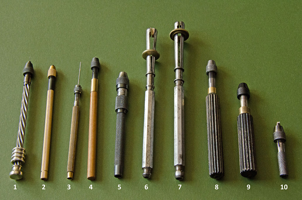
-
Well, unfortunately, the EU has clamped down on such things more strictly over the past few years. I did carry Sherline equipment from the US in my checked-in luggage, but at that time I was travelling on a UN Laissez Passer 😁. Also, there were special exemptions from import duties, when we could assure that these were 'attachments' that belonged to or complemented existing equipment you already had. The latter would also apply, when you had things imported by mail. My status has changed since and all the import duties would hit me hard ... There is also a maximum value of goods you can bring with you from outside the EU duty-free. I think it is around 300€. Above that you have to declare the items to customs and if they catch you, when you don't, the fines are hefty. Not worth the risk.
-
Chisel hone guide question
wefalck replied to CPDDET's topic in Modeling tools and Workshop Equipment
The two types of honing guides are available from watchmaker supply houses. The two-wheeled one is a standard tool for honing gravers. It is supposed to be used together with an Arkansas stone set between two wooden rails on which the wheels run. The other type was originally manufactured by a company called Barkus, I believe, to be used together with diamond wheels on watchmaker lathes. There seem to be now Chines clones available on ebay (check the area for watchmaking tools). -
The Byrnes saw has one big detriment - it's bloody expensive once it arrives over here in the EU 😬
-
... or a close shave 😆
-
I think your rope is untreated hemp for one. Another point is the quality of the hemp as such. I gather today they have to take what they get, while in the old days certain regions specialised in the production of particularly long-fibred and smooth hemp, for instance certain provinces of Russia I believe and also in Germany. The second point is the preparation of the hemp, which is quite elaborate to obtain only the long fibres, while the rest goes to waste. The third point would be how careful and tight the initial spinning was performed. Your example doesn't seem to be particularly tight. The rope-maker also goes along the rope in making with a rough cloth to rub off loose fibres. I seem to have seen rather smooth, tighly twisted ropes. So in essence, at any of our model scales one should really see any fibres sticking out. Many people now use synthetic fibres that are essentially endless and where the problem of 'hairs' sticking out does not really occur.
-
Others used wet&dry sanding paper. In ship-modelling it is frowned upon, because it is not acid-free.
-
HMCSS Victoria 1855 by BANYAN - 1:72
wefalck replied to BANYAN's topic in - Build logs for subjects built 1851 - 1900
I found the price for two pieces of CNC-milled aluminium and a thumbscrew quite steep, to which one has to add postage. Plexiglas in thin sections is quite brittle, so the edges may break out, when abused. It also depends on how often you use the tool. If I was a kit-builder and working on one kit after another with lots of PE, I might have opted for aluminium or steel. It also depends on the thickness of the sheet-metal you want to work with. The folding edges on PE are usually half-etched through lines, which are quite easy to place into these gadgets. I am working with the laser-cut paper parts, where I may score the folding line or not. Being able to see through the holding-down clamp helps in positioning the part. Another consideration for opting for a shop-made solution was, that I turned the base of my miniature edge-sander into a multi-functional tool. OK, I have now various loose pieces to take care of, but only one little box to store it.- 1,021 replies
-
- 3
-
-
- gun dispatch vessel
- victoria
- (and 2 more)
-
HMCSS Victoria 1855 by BANYAN - 1:72
wefalck replied to BANYAN's topic in - Build logs for subjects built 1851 - 1900
There are PE folding gadgets on the market (quite pricey actually). They basically consist of a slab of aluminium and a kind of straight-edge that can be clamped down on it. The straight-edge does not have vertical edges, but a slightly more acute angle that allows you to overbend to account for the springiness of the brass. Picture source: https://thesmallshop.com/collections/photo-etch-bending-tools/products/sms002-the-bug-hold-fold I made one myself, but as it was mainly meant for folding my laser-cut paper parts, I made the straight-edge from Plexiglas, so that I can better see where I place the tiny parts. Unfortunately, I don't have a picture at hand. Concerning the holes: can't you just drill at 0.5 mm or even 0.4 mm ? It is too late now, but I would have foreseen at least a dimple half-etched through or a pilot hole that could be reamed to size (using one of those five-sided reamers the watchmakers use to ream out holes in their tiny watch-hands).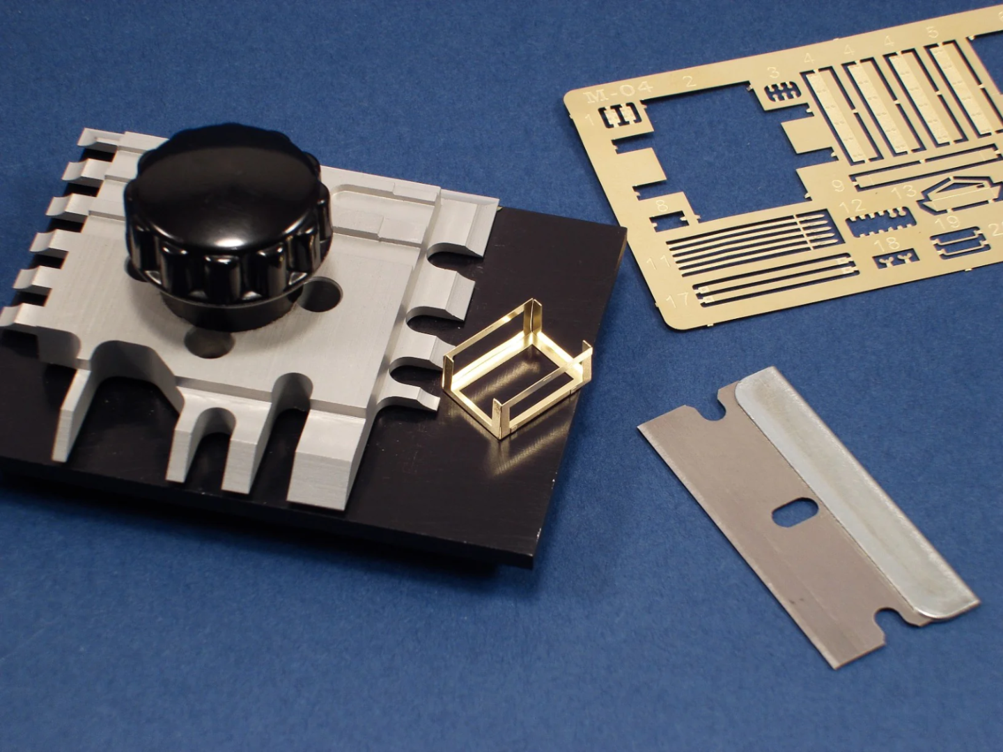
- 1,021 replies
-
- 5
-

-
-
- gun dispatch vessel
- victoria
- (and 2 more)
-
When one looks closely at the above photograph, it is a bit strange, as it seems to show only one block on the starbord-side. The end the guy holds in his hands is loaded and runs down to the block, thence (presumably to the rail and another block(?) and from there back to the tiller. The second, loose, end the guy holds runs to a block on the rail and then to the tiller, where it is made fast with a knot, it seems. Strange assymetric rigging. Steering with ropes running to a tiller (usually facing back out from the rudder!) or a yoke was very common on Arab vessels around the Indian ocean and also seem to have entered through them into some traditional Spanish boats.
-
HMCSS Victoria 1855 by BANYAN - 1:72
wefalck replied to BANYAN's topic in - Build logs for subjects built 1851 - 1900
Yep, nice metal work!- 1,021 replies
-
- 4
-
-
- gun dispatch vessel
- victoria
- (and 2 more)
-
Coming on nicely! Didn't we have discussion of the flooring already? I think panels made from individual lengths of planks, tied together with cross-pieces would be an option. These panels should be short enough to be taken out between any eventual benches etc. to allow bailing out the boat.
-
Thanks, Bob, that looks promising. I will have to look into getting one of those ... Regards from the Spanish Mainland.
-
Sealing after coppering?
wefalck replied to BBrueck's topic in Metal Work, Soldering and Metal Fittings
Not sure what you try to do, to put some sort of thick coating onto the copper that kind of covers the edges? Not sure I would want to do that, because it would change the appearance of the crispiness of the edges - otherwise the effect would be neglible. Otherwise, there several threads here that discuss the merits of preventing the copper from oxidising or otherwise. -
The original poster did not mention, what he wanted to use the tweezers for. Some additional information in this respect could lead to more specific answers. There are hundreds of different types of tweezers for different purposes, of different quality and, therefore, price. The watchmaker fraternity, in particular, uses a wide variety of tweezers for specific purposes. As they work with metal, they tend to be harder than the biological/surgical ones. Also dentists' tend to be harder. Another factor is the overall stiffness, which depends on the steel and the thickness of the material. Many reputed manufacturers now seem to sell their 'seconds' (which usually are still good enough for our purposes) through traders to the public. There are specialist traders e.g. on ebay that trade in such medical and biological tools. It may also be useful to check the on-line catalogues of medical and watchmaking supply houses to get an idea of the models available and their specific designations. Use these then to search on ebay etc. Buying tweezer online can be a bit of a hit and miss. Particularly very fine pointed tweezers I would not buy on-line, but would want to check in person their tips and how precisely they close. I bought my main 'working' tweezers in person at a watchmaking supply store some 30+ years ago. At model fairs, flea-markets and such events there are often trade stands that specialise in such 'seconds' medical etc. tools. This gives you an opportunity to check the quality. Keep on the look-out for antique equipment, the steel in them is often much better than in what is flooged new to us modellers. Having said that, those Tamiya bending tweezers I didn't know and they look quite interesting. Do they properly close along the full length of the narrow tips? Finally, if you get one of the cheaper ones for a few €/$/£ you can also grind the tips to your needs. Wouldn't do this with an expensive Dumont one, of course ...
-
Bluenose staysail halliard - confusion
wefalck replied to hamilton's topic in Masting, rigging and sails
I am not an expert on these, but looking at the arrangement and reading the explanatory text, it appears that the idea was to lead each of the halliards to different sides of the boat. In practice only one would be worked, persumably the windward one, as the leeward belaying point might be awash when racing. I think that is the idea, as otherwise there is no mechanical advantage over a single halliard. -
Well, a grand re-opening of the Museum is scheduled for 17 November this year: https://www.musee-marine.fr/nos-musees/paris/expositions-et-evenements/les-evenements/le-vendredi-17-novembre-2023-le-musee-national-de-la-marine-rouvre-ses-portes.html I have seen various projects and sat through various enthusiastic presentations by the director of the museum, but as various museology consultants got their fingers into that pie, it will not be the same as before. First of all, it seems to have mutated from a naval museum to a sort of ocean museum with the usual didactic raised finger. Second, the navy (who is the owner) seems to have succumbed to idea of a visual show, rather than to make the most of their material heritage. It seems that it will not be quite as bad as the NMM in Greenwich, but it will have far less the character of a study collection than it used to have. We'll have to see.
-
Talking about the size of models owned by the Musée de la Marine: the biggest is a fully operational demonstration model of an 18th warship that will be once again shown in the entrance hall. If I am not mistaken, it is around 4 m heigh and 6 m long ... Their ropewalk is actually of an ordinary design, that can do 3 ply and 4 ply ropes of a fixed length. The size of ropes one can do with a machine depends, of course, on the physical strength of it and the maximum weight one can put onto moving end. Conversely, it may be difficult to make very fine, say sub-mm rope with such big ropewalk.
-
The good thing about working on niche subjects is, that forgeries are less likely to occur.

