wefalck
-
Posts
6,666 -
Joined
-
Last visited
Content Type
Profiles
Forums
Gallery
Events
Everything posted by wefalck
-
 I gather, the Victorian men never kissed their brides/wifes ...
 -
Harriet McGregor by Boccherini
wefalck replied to Boccherini's topic in - Build logs for subjects built 1851 - 1900
Looking good after those challenges ! -
👍 , yep, that adds significantly to the 'historic' look!
-
Incidentally, one 'bling' thing seems to be missing: brass oil-caps (or glass vessels) on the main bearings ...
-
Very nice result, looking (almost) like the real thing! I said 'almost', because the hand-crank and the flexible drive shaft in brass are give-aways that it is model ...
-
That's an interesting approach, washes with paints that contain flakes of metal. Have to keep this in mind for certain applications ...
- 2,699 replies
-
- 3
-

-

-
- heller
- soleil royal
- (and 9 more)
-
Yes, of course, it has to be half the included angle of thread. Many (most) toothed wheels have a pressure angle of 20°, that's were the included angle of 40° comes from. Incidentally, one can cut a worm-wheel with a tap as a cutter. There are various examples on the Internet for this. I have not done this myself, but I have made hardened concave knurling wheels in that way: https://www.maritima-et-mechanika.org/tools/attachments/attachments.html#Knurl. The matching worm would be exactly the thread of that tap.
-
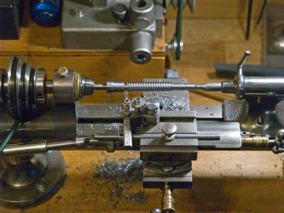
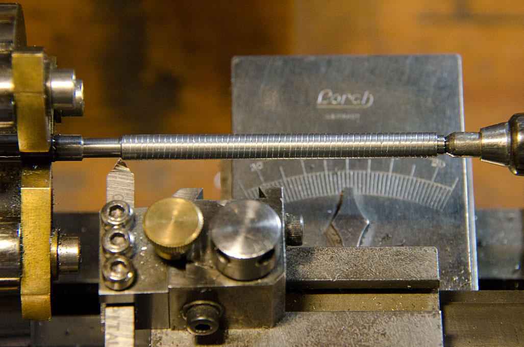
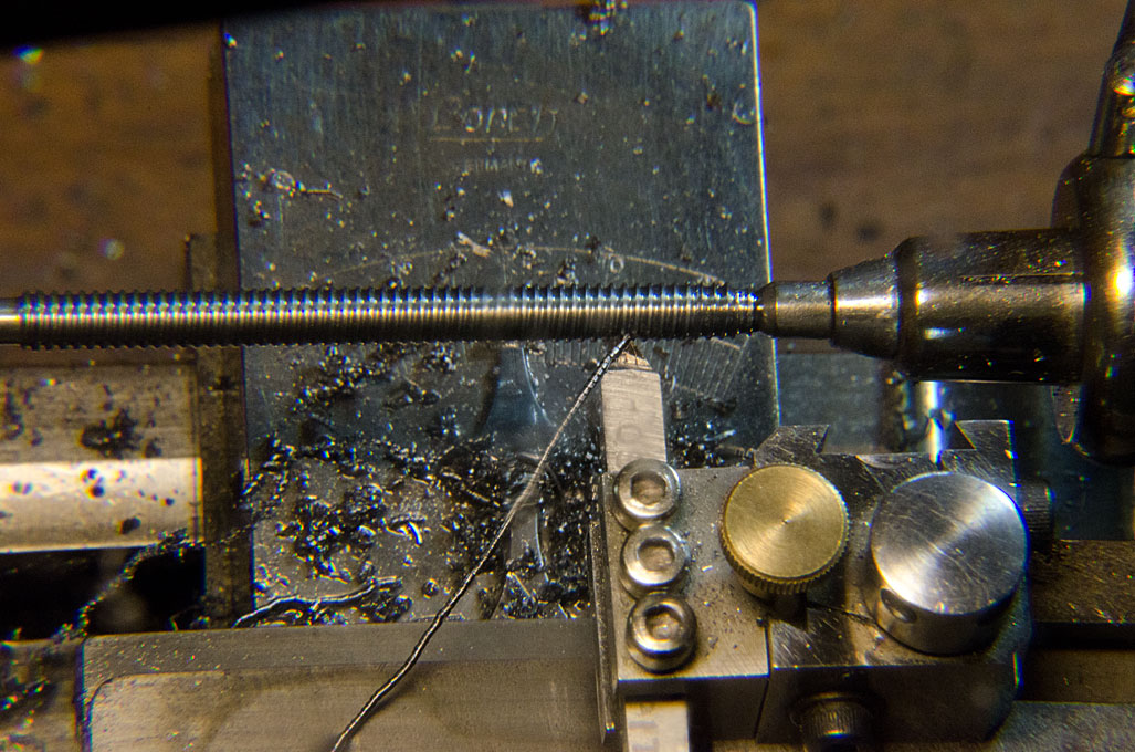
Many of these old books were written for bench-lathes, marginally bigger than my watchmakers lathe with 50 mm centre-height. The watchmakers lathe probably isn't much more rigid than the SIEG, though manufactured to much higher standards. Here I am cutting the worm for the milling machine mentioned earlier. The cutting tool is actually a brazed carbide one as used on so-called Swiss automatic lathes. Their shaft is smaller (4 mm square) than the usual ones and hence better adapted to these small lathes. Below I am making a lead-screw for a home-built micro-milling machine. I am not claiming any specific accuracy, but it works well enough for my modelling projects. In this case I used a home-ground HSS 5 mm square cutting tool: First pass to check that the pitch is correct Last pass before chasing the thread with a die
- 118 replies
-
- 10
-
-
Well, these banjo arrangements for the change-wheels haven't changed much in the last 150 years or so ... I have the same on my old watchmakers lathe. My set of change-wheels includes a 62 teeth one, which is the common option for converting imperial lead-screws for metric pitch cutting or the other way around. Given the low torque of my lathe, I made myself a crank for working the spindle by hand (Sherline offers such an option commercially) and am working with very small cuts, say 0.05 mm depth. I use an appropriately angled tool with a slight top-rake and with side clearance. The cutting speed naturally is very slow then. I have made a replacement worm for the turn-table of my watchmaker's milling machine in that way. A left-hand thread I would cut from left to right. As your lathe has a top-slide, I would set this to angle and feed in with this slide, rather than the cross-slide. In this way the cutting tool effectively only cuts on one side, which greatly reduces the cutting forces. If I have a suitable die, I would use the die for a finish cut to make sure the thread has the correct profile.
-
Absolutely, patience is the most essential ingredient ... many problems people struggle with arise from the lack of patience, from wanting quick solutions ... you are not doing it to get it ready fast, but to do a good job.
-
HMCSS Victoria 1855 by BANYAN - 1:72
wefalck replied to BANYAN's topic in - Build logs for subjects built 1851 - 1900
Personally, I would turn them from steel rod …- 1,021 replies
-
- 4
-
-
- gun dispatch vessel
- victoria
- (and 2 more)
-
I bought a basic rotary tool (no fancy ergonomic casings such as on the PROXXON or DREMEL, but very good steel collets) in around 1977 and it still one of my work-horses. Perhaps it is not so much used on wood indeed, but a shipmodel has also a lot of brass fittings that need to be shaped. Grindstones and abrasive discs are for that. Together with needle-files it also served me as a kind of rudimentary lathe before I had a real one. And, yes, I don't use it very often for drilling. Grinding and polishing are the main applications. I wouldn't want to be without it.
-
That's a good and cost-effective strategy 👍
-
Personally, I would not coat it, as this changes the surface appearance and takes away from the patinaed metal appearance. Also, a surface treatment might deepen/darken the colour, as it will fill the pores and directs incoming light deeper into the patina (similar to an optical fibre), so that less light is reflected. Apart from that, I think museums use micro-crystalline wax. I would not know any product name, but you can google for its availability in the UK. Normally, metal surfaces were sealed against (further) oxidation by zapon varnish, but the surface would be glossy, something you probably don't want this case. Applying satin or matt acrylic varnish could be another option. Once dry the varnish is inert and should not interfere with the patina. Not sure how well it might stand handling. In any case, I would test the effect first on a scrap piece of copper.
-
As to the rotary tool: I would rather look for something with collets; they are less bulky and unless you get something really cheapo with brass collets, their concentricity is much better than that of a chuck. I would also add one or two pin-vises to the list, to hold small parts, but also to hold pins for various operations and small drills. Plus drills, of course. Go for HSS, rather than carbide. Carbide breaks easily when hand-drilling - they are made for drill-stands or milling machines. And perhaps a small archimedean drill, the size of a pin-vise. It is more sensitive and less bulky than a rotary tool for drilling holes < 1 mm. For the rotary tool you may also want a set of carbon-steel and/or diamond burrs with 2.34 mm shaft. They come at moderate prices in sets of different shape and size. As your needs develop, you can upgrade. They wear out anyway over time. For the tweezers, it is better not to buy on-line - one has to check how well the points close and how stiff they are. Bad tweezers can be very frustrating. A good pair, treated well, can last for decades of modelling. My favourite pair still in daily use was bought in 1987 ...
-
So the problem is solved? Otherwise, wetting it several times, particularly in the areas with the creases and going over it with iron should solve it. Place the material so that the crease faces upward with the convex side. Otherwise, just choose areas without crease ...
-
Nice model of this colourful Mediterranean craft !
-
Which silkspan are you referring to, the fabric or the paper?
-
I was wondering what 'stump cutters' were ... I gather they are called 'burrs' around here and in the jewellers trade. The carbon-steel ones come in dozens of different shapes and sizes. There are also carbide ones, but the size and shape range is smaller. It can be worthwhile to also look into the dentists' and related range. They come from the same manufacturers, e.g. Busch in Germany.
-
That is indeed a very nice bit of sheet-metal work set into excellent carpentry. Really like the look of the sink 👍
-
Indeed, I think the re-working of the water worked out rather well and it now looks rather realistic 👍
- 333 replies
-
- 10
-
-
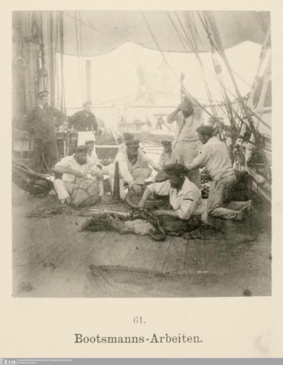
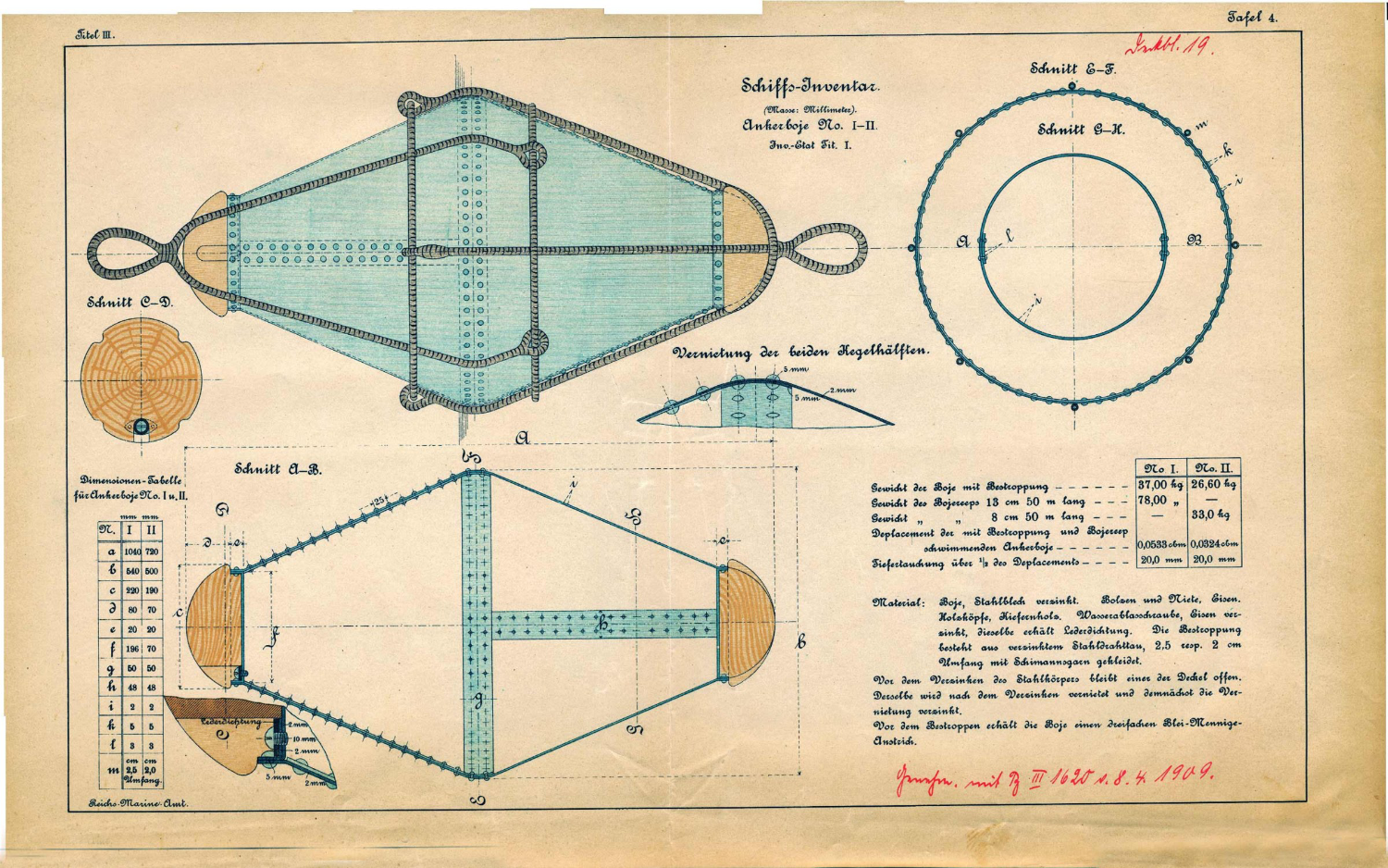
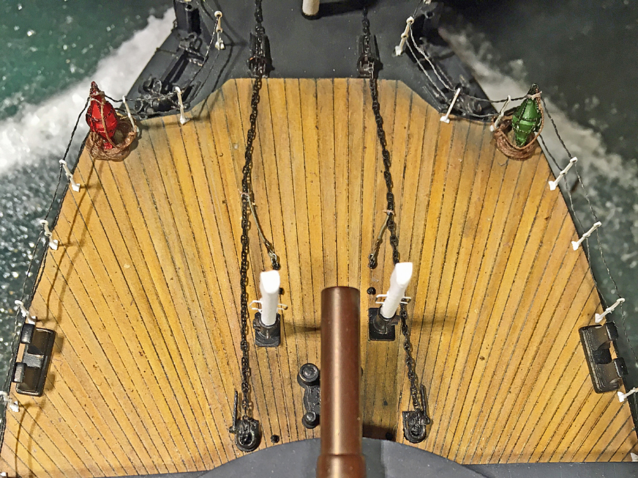
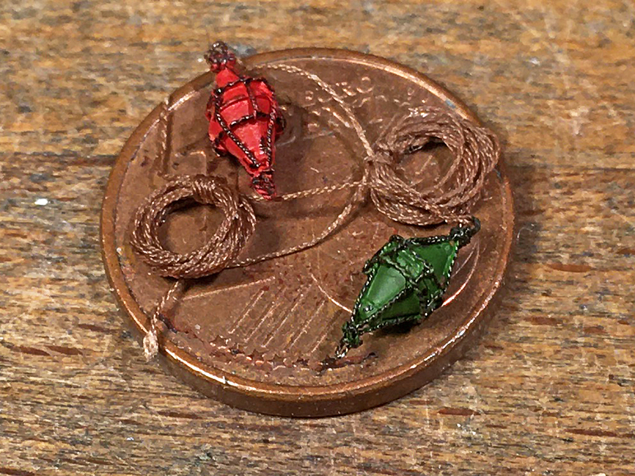
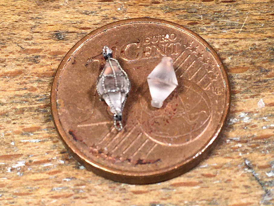
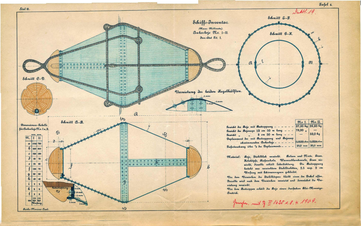
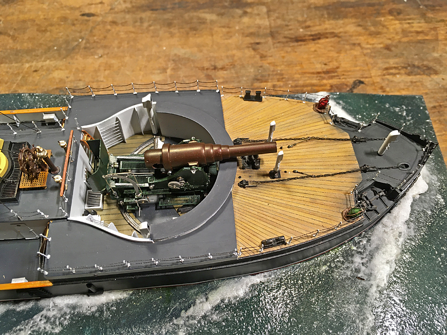
To begin with: in the meantime, I have completed the chain-rails around the barbette: This was a straightforward operation with the experience gained previously and only one corner to go around. Anchor-Buoys A fairly conspicuous detail on warships of that period were the buoys for the bow-anchors that were lashed to a convenient place near the anchor-davits, when not in use. Their purpose was to mark the location of the anchors. It was important to know, where the anchors were laid out in order to detect, whether they may have shifted and to indicate their location to newcomers, so that they don’t throw their anchors across yours, which could cause trouble, when you have to raise your anchors. At the time of SMS WESPE, the buoys were made from galvanised sheet-iron and had the shape of two cones joined at their base. A web of served wire-rope gave two attachment points, for the rope with which they were attached to the anchor and for a fishing-lanyard. Instruction leaflet from 1909 for the construction and fitting out of anchor-buoys of the German Imperial Navy. Source: https://forum.arbeitskreis-historischer-schiffbau.de/download/file.php?id=19837&mode=view. As per the official instruction sheet from which this illustration was taken, the sheet-metal was supposed to be painted in red lead-oxide primer. There is, however, no clear information in what final colour the buoys were to be painted. Typically, modeller chose green for the starboard anchor-buoy and red for the port one. There is a certain logic in this, because in this way the anchors can be identified, even if the boat may have swayed around them. There is a picture taken on board of S.M.S. HERTHA around 1876 that shows seamen working on such anchor-buoys: Seamen at work on the deck of S.M.S. HERTHA in around 1876, Source: https://sammlungen.ub.uni-frankfurt.de/kolonialesbildarchiv/content/pageview/11408859. There are two buoys visible, one on the left in a quite light grey and another one, almost covered by the seaman at the front, which is a lot darker. Considering that the glass-plate negatives of the time were less sensitive to red than to green, which would appear darker in the positive print, one can conclude that the buoy on the left was probably painted green, while the other one was probably painted red. This is so far the only evidence from the period in question for them having been painted in different colours. While the shape is seemingly simple, it is not so easy to produce and to manipulate. The two cones have to be turned separately and then fitted together. I choose Plexiglas for ease of gluing the halves together. Turning proceeded in steps: first the diameter for the wooden caps was turned and a groove to mark the overall length, then the top-slide was set over at an angle of 28° to turn the cone. As per prototype four notches were cut into the caps using a pointed cutting tool set with the cutting-edge vertical. Finally, the cones were parted off. The two cones were glued together making sure that the notches for the rope-web were offset by 45° at each end. The unpainted anchor-buoys Another consideration was how to reproduce the carefully spliced web of served wire-ropes. I decided that tightly twisted 0.1 mm diameter tinned copper-wire would be the best route. Four strands of twisted wire with a loop at the end were produced and slipped over a ring of twisted wire which then was soldered closed. The four strands were distributed equally around the ring and fixed with a tiny amount of varnish. The arrangement was slipped over the buoy, gathered together at the end and secured with a short winding of thread soaked in varnish. One of the strands was bent into an eye and secured with a half-hitch of thread. Finally, all the ends were trimmed down to the binding. The buoys then were sprayed red and green respectively and once the acrylic was dry, the wire-rope was picked out with a sepia artist’s marker pen (which seemed to give more control over the paint flow than my brushing technique). I did not take any pictures of the manufacturing process, as each step was actually quite straightforward. Finished anchor-buoys On several photographs one can see that the anchor-buoys were tied to the chain-rail near the rear anchor-davit. I don’t know how long the rope was with which the buoys were tied to the anchors, but I would think it would in the order of 20 m, accounting for typical anchoring depths. A thin ‘rope’ was produced on the rope-walk from slightly brownish material, assuming that such rope would be heavily tarred to resist its permanent exposure to the elements. A ring was formed and tied together with the buoy to the rail. Stowed anchor-buoys To be continued ....

- 935 replies
-
- 21
-
-

-
That's somewhere near the Dolomiti ... an area that saw intense action during WW1.
-
... I wonder, where in Italy this could be then? Only on one of the lakes in Northern Italy.