


wefalck
-
Posts
6,664 -
Joined
-
Last visited
Content Type
Profiles
Forums
Gallery
Events
Everything posted by wefalck
-
 There may have been a rope-ladder inboard, for instance. Below is an example from a 19th century Portuguese frigate, but it shows the idea:
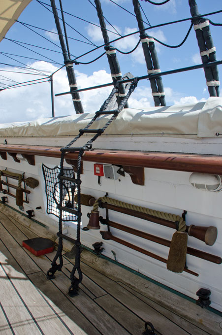
-
The steam-chest is a nice detail!
-
US 6” gun by RGL - FINISHED - Panzer Concepts
wefalck replied to RGL's topic in Non-ship/categorised builds
What about crew? -
Actually, I am not so sure about that. As a youngster I had petroleum storm-lamp and that got quite hot in places, the glass and the funnel for instance.
-
Pat, I think there was a sort of L-shaped carrier for the lamp, as Keith tried to reproduce in his first try. That's how interpret my photograph of the RELIANT. The carrier would have had two sheet-metal fingers over which sheet-metal loops at the back of the lamp would slide. During day-time the lamps would be taken down and stored.
-
US 6” gun by RGL - FINISHED - Panzer Concepts
wefalck replied to RGL's topic in Non-ship/categorised builds
A question by the side: further up you used Vallejo 'Environment, 73.826' - from the descriptions I read, it is not clear, whether these paints actually have some fluffy or gritty stuff mixed into them, or whether 'mud and grass' is just a description of the colour. Any advice? -
Another one that keeps us rivetted to MSW
-
US 6” gun by RGL - FINISHED - Panzer Concepts
wefalck replied to RGL's topic in Non-ship/categorised builds
The energy density of petrol/diesel used in an IC is by orders of magnitude higher than that of hay/oats used by a horse ... the amount of hay needed by an army (or by a city of old) is quite staggering and required considerable logistics ... plust the associated waste management. There was a continuous train of hay-waggons following the troops. -
That's exactly how I did it.
-
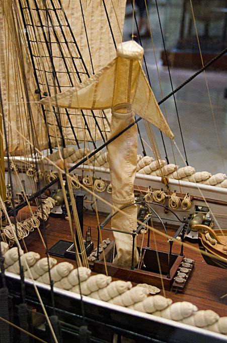
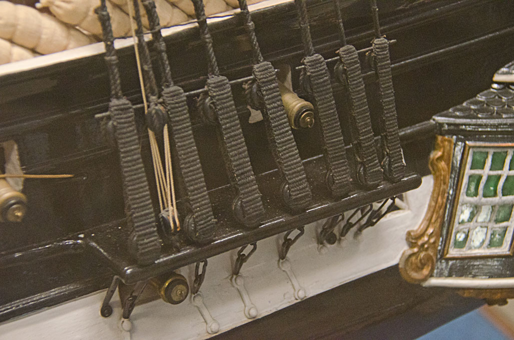
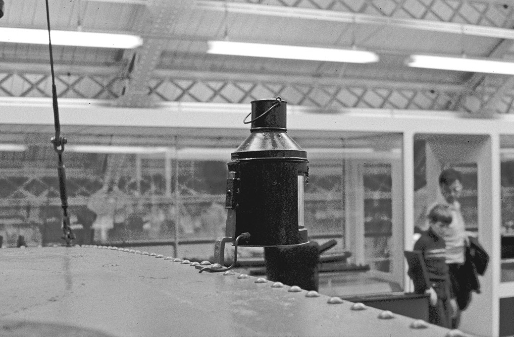
I think you likely identified the lantern rig. The second picture shows, btw, another feature that one doesn't see too often on photographs and extremely rarely on museum models, let allone on amateur models: a sailcloth ventilator. It is just forward to the lantern halliards. Off the top of my head I only recall an instruction model in the Museu de Marinha, Bélém (Lisbon), the frigate ULYSSES of 1792: The same model shows another very rarely seen feature: chafing gear as applied to the deadeyes in preparation for long crossings:
-
Carpenters make parts to fit in situ, using the part against which the second part fits as template. From an engineer's point of view this looks pretty 'artisanal', but it really works ...
-
Thanks, Bob, for the praise. I have been always on the look-out for such details that one rarely find pictured or drawn. Some 40 years ago I contemplated building a model of her and acquired a set of model-building plans available at that time. For this purpose I also took various detail photographs of fittings and 'how things were done'. In the end, I built another tug, but the photographs still were useful. What is quite amazing is, how few photographs of certain (museum) objects/ships are actually available or known of. Some years back, a history of the Manchester Docks was being written on which RELIANT ex OLD TRAFFORD worked and the only pictures of her in the museum configuration they could find, were mine ... not even the NMM seem to have had some 😲
-
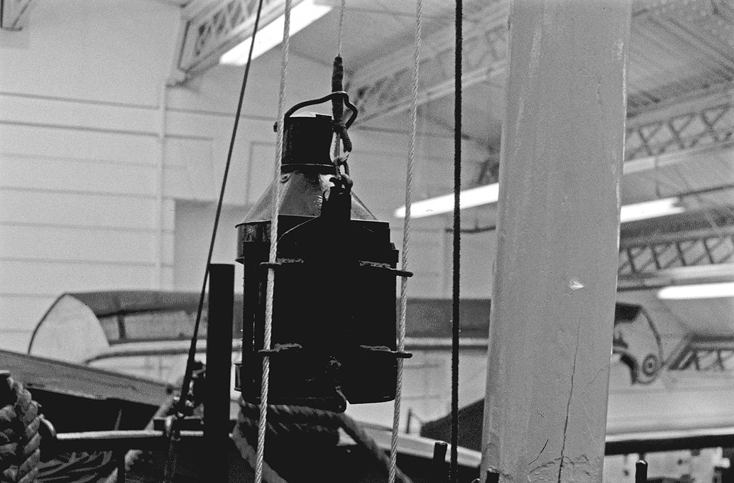
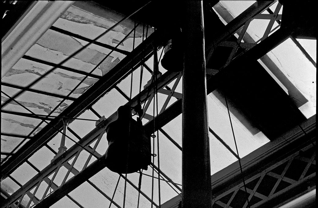
Indeed, these are very useful and enlightening discussions. This is, where the enduring value of MSW is. It's good to be able to put dates on the lighting rules, particularly when one is interested in mid-19th century subjects. I wonder, how quickly these rules were in practices adopted in areas with predominantly regional traffic, say the Baltic and skippers were struggling to make ends meet. On the subject of steamer-lights, below a couple of images from 1979 (the colour of the slides had degraded, so I turned them into B/W images) of the steam-tug RELIANT before the NMM in its unfathomable wisdom decided to scrap her. RIP. The light was guided by two stays in front of the mast. I think there was a crane for the stays at the top of the mast and they were hooked into eye-bolts in the deck, set tought with small bottle-screws. There was also a small block in the top for the halliard, but I don't have any images for the belaying point of the halliard and the down-haul. And the stern-light on a bracket rivetted to the engine-room casing: More images of her here: https://www.maritima-et-mechanika.org/maritime/reliant/reliant.html.
-
Did you develop a full body plan, with waterlines, diagonals etc.? That might be useful to check for unfair lines before you start cutting wood. It might also help to decide which half of the assymetrical bulkheads might have been the 'correct' one.
-
US 6” gun by RGL - FINISHED - Panzer Concepts
wefalck replied to RGL's topic in Non-ship/categorised builds
Where is the engine located under the driver's seat? And how is power transmitted to the clutch, via a chain-drive, as on early petrol and steam lorries? -
Which means that the outrigger/jib is fixed to the mast. In that case one doesn't need the chain and it cannot swing around, unless the mast is turning ... Ther should be also some sort of backstay(s) to counteract the weight of the material that is being shifted around. In quarries and such places sometimes a spar is used instead. Or, there is second bearing on top of the mast, if attached to e.g. building.
-
Something in the design of the derrick seems strange and that is the jaws that hold the outrigger to the mast. It is essentially designed like gaff, but then either the throat-halliard is missing or a clamp on which the jaws can rest. Like this the outrigger would just slide down and fold against the mast ... normally, on such derricks one would have a universal joint, like the ones used on the booms of some sailing ships or on ship loading derricks.
-
US 6” gun by RGL - FINISHED - Panzer Concepts
wefalck replied to RGL's topic in Non-ship/categorised builds
Interesting design with the power-shaft and the differentials on one side of the chassis. What are the heavy tubular thingies in the middle of the chassis? -
Not sure about the lighting regulations at that time. I think, when at anchor, they would have had somewhere a white lantern, but that doesn't need to be too high up. It could be also hoisted on one of the forestays. When under sail, at some stage the red and green side-lights were obviously introduced, but I do not know when exactly. Perhaps someone knows?
-
I think in the early days of electric lights, they were keeping petroleum lamps as back-up in case the generator failed etc.
-
I believe the lamps were taken down for refilling anyway. Not sure how long they would burn, but probably not more than 12h. You are probably right about the whale-oil, but that does not change their handling. Petroleum became available in larger quantities in the USA from around 1865 on.
-
In those old days, when lamps/lanterns where burning petroleum (rather than running on electricity), they were not kept at their place during day-time, but taken down and put into the lantern store, where also the petroleum (and paint and solvents) were kept. Petroleum lamps need a lot of maintanance, such as cleaning the glasses and snuffing the wick. That is presumably the reason, why you don't see them on photographs. However, the installations for hoisting and holding them could/should be visible.
-
We had this discussion in several threads now ... it comes down to what kind of boat we are talking about and in what kind of finish it is to be represented. As already noted by others, the fewer coats of paint/varnish the better in principle. I tend to play with the different shines of paint, as they would appear on the real thing. Therefore, I don't like this varnish all over as some people advocate. Personally, I put off painting as long as possible, basically to just before the final assembly. Of course, others might get impatient and need the colour to give them the impression of progress. That's psychology ... If possible I would also mount the model securely onto a temporary stand, basically a rough form of the final one. So one has to think right from beginning about the mounting and make the necessary arrangement for detachable fixtures, such as nuts cemented into the hull to take in threaded rods for instance. The stand should be big enough to provide an enveloppe of the model, including say the bowsprit. In this way you don't need to touch or move the hull around, while you are working on it, which reduces the risk of damage. Individual painted parts can be stored in (plastic) boxes lined with bits of kitchen paper towel until they are needed. This also gives the paint time to harden thoroughly.
-
Thanks Markus for your kind words and the comments. While there is enough photographic evidence for the paint schemes, when the Imperial Navy switched to grey, the evidence for the 1874 and 1878 regulations is not conclusive. On some photographs the stanchions appear quite light in colour and on others rather dark. I had considered painting the footplates black/dark grey and might still touch them up in that colour because their optical weight is indeed quite heavy. On the other hand it adds a bit of detail and the stanchions don't look like just stuck into the deck - for me it is important to also indicate how things work and parts are connected.


