


wefalck
-
Posts
6,648 -
Joined
-
Last visited
Content Type
Profiles
Forums
Gallery
Events
Everything posted by wefalck
-
 I am not an expert on the 18th century, but when you look at 19th century textbooks from different countries, you will find many different ways of construction, depending also on the deck-level and on whether it is a merchant or naval ship. In general, however, the idea is to be able to create a water-tight space below the upper deck level, particularly in mechant ships. This is what keeps the ship afloat, even if everything else above has been carried away in a storm. This means that the space between the bulwark-stanchions (or between the frames, if these have been taken up to the main rail level to serve as stanchions) has to be filled with short pieces of wood. There is usual a plank with notches for the stanchions, above these, that covers everything. Inside the stanchions/frames runs a piece of wood that is typically at least twice as thick as the deck-planking. The naming of this piece may vary, but it is typically called the water-way, as it may have concave profile facing the deck in order to serve as such, the water-way. The water-way can also be built up of several elements, but the idea is not have a seam right there, were the horizontal deck turns into the vertical bulwark - which would be the corner, where water might collect and then cause rot along the seam. Depending again on the style of deck-planking, the period and the size of the vessel, there may be a wider deck-plank running inside the water-way, which would be the margin-plank. It has the same thickness as the deck-planks and is needed, when one want to nib the deck-planks into it at the bow or stern sections. A normal deck-plank would be too narrow to allow other planks to be nibbed into it. On ship, where the deck-plank is running at an angle against the water-way, without any nibbing, there is usuall also no margin-plank. However, such seems with acute angles are difficult to caulk properly.
 -
As Allan said, price of the pigment was probably the determining reason. Red ochre was readily available in many parts of Europe and has excellent covering capabilities and weathering resistance (it is the end-product from weathering other rocks, particularly iron-bearing limestones, after all). From the second quarter of the 19th century on, fashion seems to have changed, when lead-white began to produced in larger quantities, bulwarks were painted white or sometime in pale green, yellow, blue or even in pink, when some other pigment was added to the lead-white.
-
Thanks for the hint. I have to check the compatibilities. While I do all the CAD-work on my recent Mac, the laser-cutter is run off an older MS Windows XP computer. The current driver for the laser-cutter is not available for MacOS. If I could run the laser-cutter directly off the Mac, that would make things simpler. All the artwork is done on EazyDraw and then converted in JPGs and then adjusted to the correct size in Photoshop. However, we digressing with this discussion from the original subject of the thread ...
-
Yes, but if there were several guys walking close to each other they would leave multiple traces ...
-
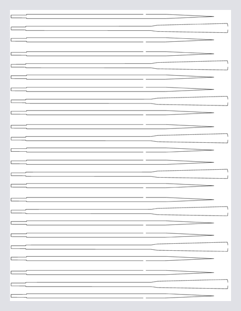
As an add on, I have a cheapo small laser-cutter that works with bit-images, rather than vector-graphics. Below is the image that was used to cut the oars: The oars are about 22 mm long.
-
Just had a look at the SWSM forum and there seems to be a lot of interesting stuff there. Thanks for the reference!
-
Titanic's Waterline
wefalck replied to Kelp's topic in Building, Framing, Planking and plating a ships hull and deck
A small correction: in those pre-grey naval days certain navies had a white stripe about half a metre above the CWL. -
I recently made a bunch of oars in 1:160 from three layers of laser-cut paper: Unfortunately, I didn't take pictures of the process itself. However, they are laminated from three layers of 0.2 mm thick 'Canson' paper, trying to more or less reproduce the varying cross-sections and longitudinal profile. The layers were cemented together using varnish, which hardens the paper and makes it also amenable to (light) sanding.
- 58 replies
-
- 12
-

-

-
Titanic's Waterline
wefalck replied to Kelp's topic in Building, Framing, Planking and plating a ships hull and deck
There were two (traditional) and one psychological reasons, why the separation between the top- and the bottom-colour or the bootstrapping where made to curve slightly upward. - the viewing psychology reason is that when you have a curved line (the sheer-line) and a straight line have above each other the straight line appears to be curving slightly downwards (hogging). So to counteract this the separation line was given a slight curve upward towards the ends. - a curved line looks more dynamic than a straight line and gives the impression of speed - older (wooden) ships tended to 'hog', i.e. because the ship ends have less buoyancy then the middle, prolonged exposure to heavy seas leads to a slight sagging of the ends. So painting the 'water-line' curved upwards will mask this effect visually. -
So we agree I think coal-tar became available in large quantities from around the 1840s on, when gasworks were set up in many European countries to produce gas for street- and then domestic lighting purposes. Coal-tar is a waste product from the gasification of coal, but the amount depends on the type of coal.
-
Are you sure? Yes, yarns where lightly tarred before going onto the rope-walk, but when in use, running rigging was not tarred further. The question Johann raised was, whether block-strops were tarred all over once the strop was completed. The answer is probaly 'yes', but the amount of tarring was probably less than on most elements of standing rigging. In the age of 'Stockholm'-type tar, the tarring was less obvious than in later days, when coal-tar and -pitch became available.
-
When it comes to building 'rotten' sceneries, I found this Swiss guy most inspirational: https://www.pinterest.fr/ackle0238/my-models-135-scale/. He has also the talent to pull everything together, so that the little bits and pieces and details look as if they belong there, rather than put there - I found this the most difficult aspect of making sceneries.
-
Mark, I appreciate the circumstances under which you are creating this model. There are, however, a lot of free on-line resources that may help answer your questions, but that are not so easy to find using Google, if you don't know what to look for. The above drawings from the navy-yard in Copenhagen are completely free and downloadable: https://www.sa.dk/ao-soegesider/da/other/index-creator/40/3353816/17149179. I didn't have the time to go through the drawings, but there may be one of them that answers your question about these misterious seven features. There are also water-colours for the bow- and stern-decorations.
-
I am looking not too often into the section on kit-projects, mainly because the subjects are not so much of interest to me - my interest focuses mainly on mid- to later 19th century subjects. This includes mixed sail/steam naval vessels. It may be a bit late in the game, but over the years I have collected quite a bit of information on JYLLAND, simply because a lot of information is available on her. Here is, what I think, a pretty comprehensive list of literature on her (a B denotes that this is a book, an E means that it is available on the WWW in digital form) B - FELDTHUSEN, P.A., JEPPESEN, A. (1944): Fregatten Jylland i Krig og Fred.- 175 p., København (Gyldendalske Boghandel). E - Frantzen, O.L. (1980): Fregatten Jyllands Artilleri.- Marinehistorisk Tidskrift, 13(3): 7-25, København (Marinehistorisk Selskab). B - HAMMER KJØLSEN, F. (1962): Fregatten Fortæller til Orlogs med Jylland for 100 Aar siden.- 155 p., København (Nationalmuseet/Rhodos). B - KURE, B. (1995): Historien om fregatten Jylland.- 107 p.København (Høst & Son). E - Steen Steensen, R. (1961): Fregatten Jylland.- Marinehistorisk Selskab skrift nr. 9: 59 p., København (Nationalmuseet). As you will at some stage get to the artillery, here are some references to Danish artillery. I only listed those Danish sources that might be relevant to her main active period: E - Andersen, P. (1909): Bidrag til Sjøartilleriets Historie. Udgivet med Understøttelse af Marineministeriet.- 189 p., Kjøbenhavn. E - Anonym (1864): Oversigt over Udrustningerne fra November 1863 til November 1864.- Tidsskrift for Søvæsen: 345-374, Kjøbenhavn. E - Anonym (1871): For- eller Bagladekanoner til Skibsbrug?.- Tidsskrift for Søvæsen, Ny Række, 6: 187-193, Kjøbenhavn. B - ANONYM (1873): Haandbog for Sø-Artilleri-Exercerskolens Elever.- p., København (). E - Blom, O. (1864): Om Flaadens Bevæbning.- Tidsskrift for Søvæsen: 306-339 / 401-430, Kjøbenhavn. E - Blom, O. (1869): Flaadens Riffelkanoner.- Tidsskrift for Søvæsen, Ny Række, 4: 230-244 / 301-319, Kjøbenhavn. E - Frantzen, O.L. (1980): Fregatten Jyllands Artilleri.- Marinehistorisk Tidskrift, 13(3): 7-25, København (Marinehistorisk Selskab). B - Frantzen, O.L., Mortensen, M.H., Probst, N.M., Thiede, S.E. (1999): Dansk søartilleri 1400-2000.- 64 p., København (Tøjhusmuseet). E - Jessen, T. (1876): De riflede Kanoners Udvikling i vor Flaade.- Tidsskrift for Søvæsen, Ny Række, 11: 193-, Kjøbenhavn. E - Tuxen, N.E. (1861): De nyere Krigsskibes Artilleri og Skibenes Blendering.- Tidsskrift for Søvæsen: 81-112, Kjøbenhavn. And finally, here is a list of the drawings on JYLLAND and her sister ship NIELS JUEL in the Danish archives (sorry, some of the explanations are in German - I did not have the time to translate them): B-240 NIELS JUEL.jpeg G-1859-01 NIELS JUEL - JYLLAND.jpeg G-1860-03 NIELS JUEL - JYLLAND.jpeg G-1861-05 NIELS JUEL - JYLLAND.jpeg G-1862-07 NIELS JUEL - JYLLAND.jpeg G-1863-09 NIELS JUEL - JYLLAND.jpeg G-1864-11 NIELS JUEL - JYLLAND.jpeg G-1865-13 NIELS JUEL - JYLLAND.jpeg G-1866-15 NIELS JUEL - JYLLAND.jpeg G-1867-18 NIELS JUEL - JYLLAND.jpeg G-1868-20 NIELS JUEL - JYLLAND.jpeg G-1869-22 NIELS JUEL - JYLLAND.jpeg G-1870-25 NIELS JUEL - JYLLAND.jpeg G-1871-27 NIELS JUEL - JYLLAND.jpeg G-1872-29 NIELS JUEL - JYLLAND.jpeg G-1873-31 NIELS JUEL - JYLLAND.jpeg G-1874-33 NIELS JUEL - JYLLAND.jpeg G-1875-35 NIELS JUEL - JYLLAND.jpeg G-1876-02 NIELS JUEL - JYLLAND.jpeg G-1877-04 NIELS JUEL - JYLLAND.jpeg G-1878-06 NIELS JUEL - JYLLAND.jpeg G-1879-08 NIELS JUEL - JYLLAND.jpeg G-1880-10 NIELS JUEL - JYLLAND.jpeg G-1881-12 NIELS JUEL - JYLLAND.jpeg G-1882-14 NIELS JUEL - JYLLAND.jpeg G-1883-16 NIELS JUEL - JYLLAND.jpeg G-1884-19 NIELS JUEL - JYLLAND.jpeg G-1885-21 NIELS JUEL - JYLLAND.jpeg G-1886-23 NIELS JUEL - JYLLAND.jpeg G-1887-25 NIELS JUEL - JYLLAND.jpeg G-1888-27 NIELS JUEL - JYLLAND.jpeg G-1889-29 NIELS JUEL - JYLLAND.jpeg G-1890-31 NIELS JUEL - JYLLAND.jpeg G-1892-02 NIELS JUEL - JYLLAND.jpeg G-1893-05 NIELS JUEL - JYLLAND.jpeg G-1894-07 NIELS JUEL - JYLLAND.jpeg G-1895-09 NIELS JUEL - JYLLAND.jpeg G-1896-01 NIELS JUEL - JYLLAND.jpeg G-1928-09 NIELS JUEL.jpeg G-1929-11 NIELS JUEL.jpeg G-2196-01 JYLLAND Artillerie.jpeg G-2337-01 JYLLAND Faalreep.jpeg G-2436-05 NIELS JUEL Finkennetze.jpeg G-3053-03 NIELS JUEL.jpeg G-3054-05 NIELS JUEL.jpeg G-3055-07 NIELS JUEL.jpeg G-3060-01 JYLLAND.jpeg G-3062-01 JYLLAND.jpeg G-3452-08 NIELS JUEL als Wohnschiff.jpeg G-3453-10 NIELS JUEL als Wohnschiff.jpeg G-3454-12 NIELS JUEL als Wohnschiff.jpeg G-3455-14 NIELS JUEL als Wohnschiff.jpeg G-4669-71 NIELS JUEL Küche.jpeg G-4705-03 JYLLAND Küche.jpeg G-4882-05 NIELS JUEL (1855) Großmast.jpeg G-4883-07 NIELS JUEL (1855) Mastdoppelungen.jpeg G-4884-09 NIELS JUEL (1855) Marsen.jpeg G-4885-11 NIELS JUEL (1855) Großmast.jpeg G-4886-13 NIELS JUEL (1855) Salinge.jpeg G-4889-19 NIELS JUEL (1855) Großmast.jpeg G-4890-21 NIELS JUEL (1855) Schloß Großmarsstenge.jpeg G-4892-25 JYLLAND (1860) Masten.jpeg G-4893-27 JYLLAND (1860) Bugspriet, Baum, Gaffel.jpeg G-4894-29 JYLLAND (1860) Stengen.jpeg G-4895-31 JYLLAND (1860) Unterrahen.jpeg G-4896-33 JYLLAND (1860) Brahmrahen.jpeg G-4897-35 JYLLAND (1860) Doppelungen, Marsen.jpeg G-4898-37 JYLLAND (1860) Brahmrahen, Leesegelspieren.jpeg G-4899-39 JYLLAND (1860) Doppelungen, Salinge.jpeg G-4900-41 JYLLAND (1860) Marsen, Salinge.jpeg G-4912-03 NIELS JUEL (1856) Stengen.jpeg G-4978-05 NIELS JUEL (1856) Heck- und Seitendavits.jpeg G-4979-07 JYLLAND (1860) Seitendavits.jpeg G-5175-59 NIELS JUEL (1856) Ruderanlage.jpeg G-5288-03 NIELS JUEL (1856) Brown & Lenox Patentspill.jpeg Hope this information will be of some use in your further endeavours.
-
Shellac lost its popularity as furniture finishing because on such surfaces one can easily leave water- and alcohol-staines - in fact acohol is the solvent during application and it can be easily re-dissolved in this. Unlike certain other surface finishes it does not harden by e.g. cross-linking reactions, but simply by the evaporation of the solvent. However, it makes an excellent surface treatment or adhesive for models. You can use it to kind of 'harden' the wood by rubbing off most of it with steel-wool, achieving a sort of bare wood look, or a classical high-gloss 'French Polish'.
-
The thingie on the right is probably the base of a horizontal milling machine or a metal shaper - see for instance the building-log of a model of such here on MSW:
- 333 replies
-
- 11
-
-
The default options on virtually every piece of wood would be wood-tar or lineseed oil, a procedure that would be repeated every now and then. On a model shellac solution or a wood-filler would do the job. Typically masts were made from some species of pine and therefore would have a quite light colour that changes into something like a honey colour, once the wood-tar or lineseed oil has been applied. Mast on which gaffs are sliding up and down probably were left natural (but preserved with tar or oil), as the gaff would wear off the paint quickly. Otherwise, as Phil explained, colours were subject to fashion and spars could be quite colourful in some ages and regions.
-
Not sure, where the problem is here. It seems to be pretty bog standard later 19th century construction. One just has to sand flat/taper the gaff/boom at the end to provide a seat for the jaws. Glue suitable pieces of wood to either side and then round out according to the large diametre of the mast. Finally shape the outside of the jaws. Drill the required holes and make the small 'clapper' piece. On the real thing there would have been either three bolts going horizontally through the jaws and the boom/gaff (one would also serve as pivot for the clapper piece) or there would be three bands around the assemblage.
-
US 6” gun by RGL - FINISHED - Panzer Concepts
wefalck replied to RGL's topic in Non-ship/categorised builds
For a 'first' they look pretty good! I haven't done any 1/35 scale figures for decades, but one thing I learned, was to make sure that the iris of the eyes is partly covered by eyelids, otherwise one gets a sort of shell-shocked look (which can be appropriate of course ...). -
Well, yes, as square broach would have been the thing to use ... I wonder, why they suggested this somewhat difficult operation, there would be other ways to secure a square cutting tool at the front of an arbor.
-
Had to do quite a bit of travelling recently and only had time to occasionally glance over MSW - so I missed the beginning of this new project. The subject is not really 'my' period and I am not a great fan of scallops either - however, I am looking forward again to a nice exercise in first-class modelling 👍
-
In principle NC existed since 1805, when the Jacquard-loom was patented, which uses control-cards ... the same principle was used in fairground-organs and pianolas from late 19th on. It is in interesting question, why this principle was not used earlier to also control toolroom machines. I gather automatic milling machines are more difficult to realise, because of the need to change the workpiece, which typically were cast items, rather than bar-stock, as in the automatic lathes. ... but we a veering off the subject of this thread.
-
In most cases the 'automation' only concerned disengaging carriage drives, but by the end of the century certain 'screw' lathes to turn small parts, such as screws obviously, were automated and controlled mechanically from templates cut from sheet metal. Mechanically they were quite sophisticated. Shapers and planers typically had automatic table advances using ratchet-wheels and ratchets driven by excentres. I am not sure that such features where ever installed in milling machines.
-
I didn't see the drawing before, but all these machines had such carriage stops, as they were intended for production work. My mill has little screws in the stops left and right, that allow a fine adjustment of the carriage movement. In other cases these stops acted on a dog-clutch that would disengange the carriage drive.
-
Not sure that this statement holds in general. It depends on whether you talk about square sails or fore-and-aft as well as many other design features of the rig. The main point of chafing between square sails and rig would be the shrouds. But here it depends on the parrels or cranes that would be used to support the yards and how far away they are from the mast. Overall, I don't think that one or two degrees more or less in rake does have a very significant effect on chafing.

