


wefalck
-
Posts
5,574 -
Joined
-
Last visited
Content Type
Profiles
Forums
Gallery
Events
Everything posted by wefalck
-
 Pat, I don't have hands-on experience with drafting linen, only know it from some old drawings in archives. However, I think the thinner the material, the better. Such canvas straps would be perhaps 3 mm thick at most in real life.
 -
I think Bob above with his reasoning is right. I would expect the copper to be a dullish penny-brown below the water line, some verdigris (i.e. copper sulphate-oxide) around the waterline and again some more penny-brown higher up, depending on how much above the waterline the coppering goes. Incidentally, the bronze ram and stern-post should retain a more yellowish colour, perhaps with a hint of brownish green - the tin in the bronze doesn't really form sulfates in seawater conditions.
-
Why do you call this 'Mondfeld's' jig? This kind of jig has been shown decades before he wrote his books by e.g. Underhill, Curti and others in their respective books ...
-
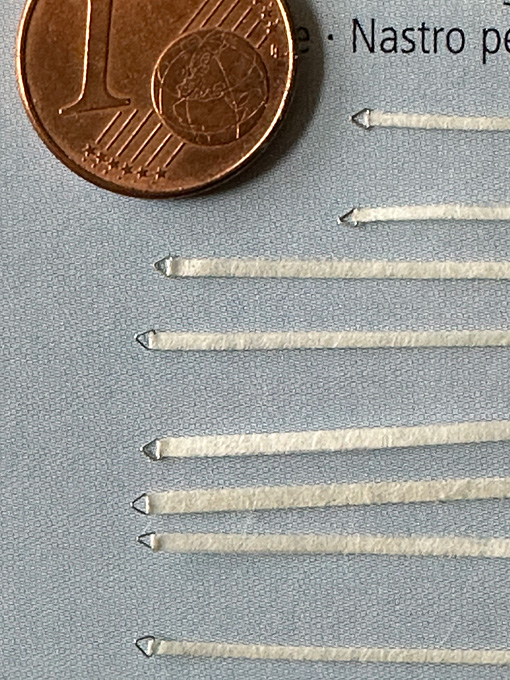
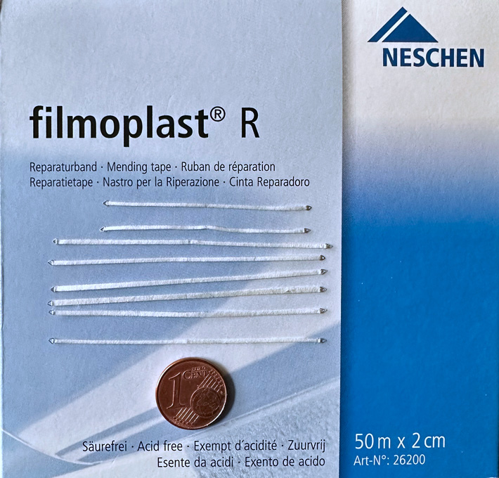
Thanks, gentlemen, for your kind comments! Pat, I obtained the tape from a local art supply store. Here is the link to the manufacturer's Web-site: https://www.neschen.de/en/product/filmoplast-r/#pdetails. They probably sell world-wide, but I would suspect that there are other manufacturers with similar products. Basically it is an extremely thin silk-paper to which a film of heat-activated acrylic compound is attached. This acrylic film actually detached quite easily and could be used even for other applications.
-
Shellac solution has been used for centuries to stiffen paper. You will have to experiment with the right alcohol to shellac ratio. I use a thick solution as glue.
-
I don't think there is one type of card that fulfills all the requirements one may have. I hasten to add that I am not 'cardboard-modeller', but I use card in my models. This is a huge difference. Cardboard-modellers, at least those working from kits, do not normally paint or otherwise surface-coat their models, while I do. A key question is: do you care about acidity and cheap wood in the cardboard or don't you care about the longevity of your model. A lot of cheap cardboard in not neutralised in terms of pH and, therefore, the material may/will disintegrate with time. I would always go for high-quality material from artist supply shops. Personally, I prefer high-density papers that have been calandred heavily (i.e. pressed strongly between steel rollers) to give a smooth surface. The name to look out for is Bristol-board, which is available in different thicknesses, i.e. different weights per sqm. Unfortunately, my cheapo 3W laser-printer cannot handle white dense paper. The best solution I found is dark-brown 'Canson'-paper. This is less dense than Bristol-board, but still has a reasonably smooth surface. In fact, I create a sort of composite material by soaking the Canson-paper in varnish. Other people use thin CA glue, but I am not fond of CA. The varnish gives the paper a limited capability to be sanded. One may need to resoak the paper at the sanded edges to stabilise them and reduce the 'fuzz'.
-
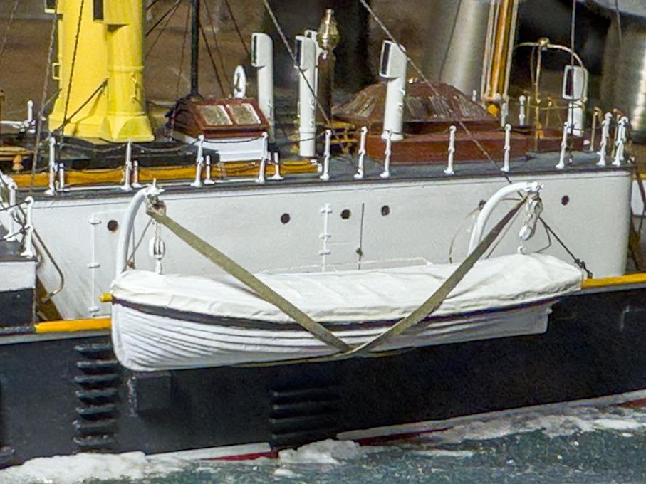
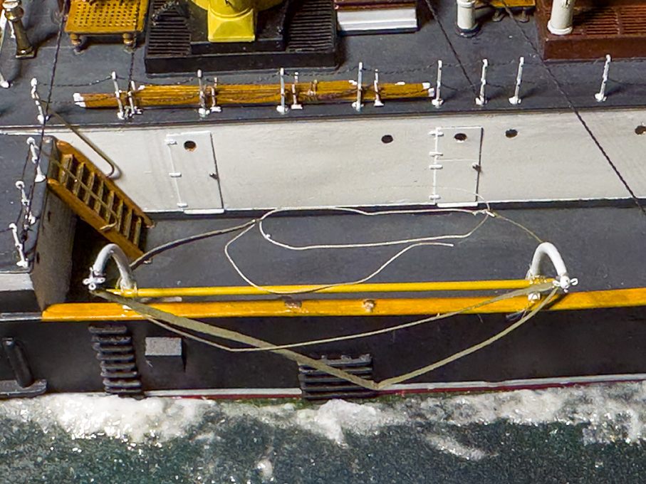
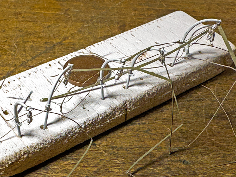
Thanks, belatedly, gentlemen ... Well, some traveling and struggles with tiny and flimsy parts caused again a long delay until this update … Installing the ship’s boats This detail was the most dreaded of all, due to the flimsy character of the parts. The davits had been produced a long time ago, as were the blocks for the hoisting tackle, and, of course the four boats. There are no pictures, except the very first photograph of SMS WESPE that indicate the arrangements for the boats hanging outboard on the davits. While it seems to have been a quite common arrangement on smaller warships of the time, it was already noted in reports by captains of Prussian gunboats ten years earlier, boats in such a position are prone to be carried away by seas of even moderate height. So, quite early on barrings and boat skids had been installed on the WESPE-class boat and the davits lengthened to lift up the boats. For this final arrangement, various images are available. Somehow, the boats must have been prevented from swinging in their hoisting gear. A typical arrangement would have been a spar lashed across the davits and the boats pulled against them with cross-wise boat ties. In the absence of other pictorial evidence, this is what I opted for. There were, however, still some detail questions open: were those ties strips of heavy canvas or braided rope-work and did the spars have bolsters around them to prevent damage to the boats? For the latter questions there are examples of both option on photographs and (contemporary) models. I recently visited again the Maritime Museum in Stockholm, which reminded me of a possible solution on a model of the same period. The boat-ties seem to have been heavy canvas and had triangular rings at their ends. They are attached to an eye at the top of the davit, run around the boat, then around the opposite davit, and are hauled taught with a tackle of blocks hooked in between them. No bolsters on the spars. I decided to leave out the tackle and just use a lashing between the rings to tighten the ties. The lashing will be difficult enough to access behind the boats. Boat ties arranged on a package of book-repair tape The triangular rings were fashioned from 0.15 mm tinned copper-wire wound around the tang of a triangular file with 1 mm sides. The windings were cut open with a scalpel. The ties themselves are narrow strips of a special kind of material: a kind of very fine silk-paper tape with a backing of a thermos-setting acrylic glue. This material is used in book repair for instance. Brand and other details can be seen on the photograph. The 1 mm strips were cut with a new no. 11 scalpel blade and folded in two. The material is slightly tacky which is helpful when aligning the halves and inserting the rings. The glue was set with the help of my hot-air soldering gun set to 110°C as per instructions. The halves were pushed together using a tool as used in the old days to rub down transfer lettering. The ties were painted in Vallejo ‘hemp’. Boat ties in detail It took some tries to work out a workable sequence for installing the davits, spar, boat-ties and boat-tackles, considering also the difficulty of access. Eventually the ties were fastened to the davits and the tackles hooked into the latter with the loose end already belayed to the clamp on the back of the davits. Davits fitted out and ready for installation on board The davits then were inserted into their sockets and fixed with a drop of white glue. Next the spar is lashed to the davits. Then the ties were arranged in preparation of the boats and the lashing is reeved. Davits ready to receive the boat. The davits are now ready to receive the boat, which is slipped in and the tackles hooked into the respective rings on the boat. The ties are now pulled tight, so that boat rests against the spar. Boat stowed in the davits. Overall, the installation of the first boat went reasonably well. However, it is hanging a few millimetres too low. The boat’s keel should have been level with the bulwark handrail. Somehow, I didn’t manage to make the close-hauled tackled as short as it should have been. Also, the hooks on the blocks are a tad too long. Not 100% satisfactory, but I am not going back two steps to remake the blocks and tackles and all. Let’s assume the crew hasn’t done such a good job in stowing the boats and the officers haven’t noticed it yet … To be continued ....
- 889 replies
-
- 27
-

-

-
It's not the rod that flexes, but possibly the rod in the base-plate ...
-
Pulled the Trigger == Lathe coming
wefalck replied to kgstakes's topic in Modeling tools and Workshop Equipment
Well, it's difficult to give here a crash-course in turning ... most of the time one would cut towards the chuck, as the main spindle-bearing is designed to take up the cutting forces. However, there are many situations, when one needs to cut away from the chuck, but one would do this for as little material as possible. For the smal pieces in modelling and working with easily turned materials, such as brass or aluminium, a life centre is not really needed, a hard fixed centre is the more precise option. Always lubricate well. When turning wood, the situation is different, as one cannot lubricate and the friction between wood and steel is considerable. So a life centre is needed for longer parts. You probably will find an aftermarket life centre with an arbor of the same diametre as you already have. To my knowledge, the Taig lathe is not bored for any Morse-taper tooling, neither in the spindle nor the tail-stock. Except for MT0 all the MTs would be too large for this small lathe. There are various degrees of freedom, when aligning a lathe: the height and angle (vertical and horizontal) of the spindle relative to the bed ways, the height and angle (vertical and horizontal) of the tailstock axis, the straightness of the bed etc. Most of them are set by the manufacturing tolerances of the lathe and it is not so easy to correct these. So having a test-bar may not be terribly useful, as any corrections (if needed at all) would involve an extensive scraping or shimming action. However, the Taig tailstocks can be 'set-over' for taper-turning, i.e. moved perpendicular to the axis of the lathe. This means that every time you have loosened the locking screw, you would need to re-align the tailstock. An old-time machinists' approach is to use two fixed centres, in the spindle and in the tailstock, and hold a razor-blade between them. If the centres are aligned correctly, the blade should be perfectly vertical and at 90° to the bed. Otherwise, I would not get worked up too much about such alignment issues, as they are likely to be well within the tolerances we are working in. On my watchmaker-lathes I can easily work to within a 1/20 or even 1/50 of a millimetre. That should be more than good enough for shipmodelling purposes, unless perhaps you are building a steam-engine. I would guess, that on the Taig you can also work to 1/20 of a millimetre (assuming that the handwheels are graduated at 1/10 or even 1/20. -
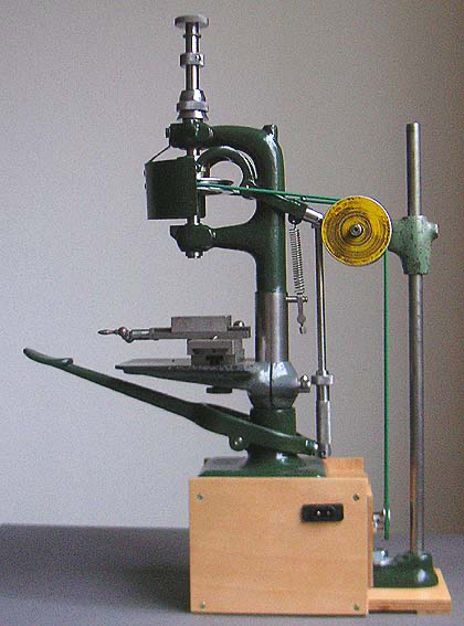
The main body that houses the spindle as well as the table apear to be pupose-machined parts, the rest is probably off-the-shelf stuff that can be easily sourced on Amazon, ebay, etc. In fact, one could fabricate easily such a drill-press from parts sold for 3D-printers or CNC-mills. Rods and bearings can be found in all sorts of dimensions in the Internet. As to longer columns: the longer the column the more flex there is, which may be not so good for small fragile drill-bits. In fact, the melamin riser-blocks may be not such a bad idea at all.
-
I would be surprised, if the spindle used anything else than ball-bearings. Ideally there should be three: two radial ones and a third axial one to take up the force from drilling. The seats can be easily machined on a CNC mill. There would need to be a sleeve on the spindle to take up end-thrust. All in all the parts would cost only a few €/US$/£ … no point to mess around with brass bearings.
-
Are you sure it’s the spindle and not the guiding sleeves for the up and down movement?
-
I think a lever as such is not the problem when using sub-millimetre drills, but rather the position of the arm when using the lever. You have to be able to rest the arm on the table as much as possible, perhaps working only from the wrist in order to reduce the number of degrees of freedom you have to control. In the watchmaking etc. industries they have used such drill-presses for something like 150 years now: The preferred brand of Jacobs-chuck there is 'Albrecht', but they are ridicously expensive (we talk about several hundred €/US$/£ when new). The above machine used horological collets, but a less expensive option is to use ER7 or ER11 collets for which arbors are available to screw on in place of a drill-chuck. There HSS sub-millimeter drill-bits on the market that have 1 mm shafts. Their spiral is in order of 5x the diametre long, so they are relatively stiff and do not wander. I use a carbide scriber as centre punch to locate holes. I have not had a chance to closely inspect any of these small drill-presses that sparked off this thread, but think they could be a useful tool, perhaps with some upgrading to ensure no play in the mechanical parts.
-
No, it wouldn't, as soft solder is an alloy of tin with some other metals, mainly lead in the old days, to reduce and control the melting point. These metals/alloys do not form black sulfides under the chemical conditions of a simple 'liver of sulfur' solution.
-
Pulled the Trigger == Lathe coming
wefalck replied to kgstakes's topic in Modeling tools and Workshop Equipment
6 mm holders for triangular inserts are readily available from model engineering shops. I know sources in the UK and continental Europe, but wouldn't know any in the USA. Beware that all those inserts have rounded corners, so are not really suitable for turning sharp shoulders. Grinding HSS-lathe tools for brass work is not a great magic, if you go about it systematically. I still found this the best option for really small pieces that need sharp inside corners. Once ground, I hone them from time to time on an Arkansas-stone. As there is no top-rake for brass, you can just rub the bit flat on the stone. -
Oh yes, now I remember having read about the 6° oddity. No idea for what rational might have been behind this added complication. If the angle pointed forward, I might have said that it would resulted in less chamfering and perhaps actually a stiffer hull - when the bow pounds into waves there would be less of a tendency that the hull is pushed in as the frames are pushed back. On the other hand, the reverse logic may also apply, meaning that frames inclined backward might make the hull a bit more flexible and therefore more resilient (a principle that has been dicovered by the Vikings actually).
- 88 replies
-
- 6
-
-
- Vigilance
- Sailing Trawler
- (and 1 more)
-
Pulled the Trigger == Lathe coming
wefalck replied to kgstakes's topic in Modeling tools and Workshop Equipment
Talking about parting-off: our small lathes are just not rigid and stiff enough for stress-free parting-off of anything say above 6 mm diameter, even when you use so-called parting knives. What I do is that I first cut a narrow groove and then complete the parting-off with a fret- or hacksaw while the machine is running at very slow speed. One has to do this very cautiously, particularly when the part is held in a jaw-chuck, and make sure to keep the head/face out of the line of cutting in case there is a snag or backlash. My most used cutting tool is an HSS-toolbit that is ground like a grooving bit with straight cutting face of 0.4 mm width at the front. This allows me to machine most small parts without changing the tool and therefore loosing measures. For brass the bit has zero top-rake, for steel, aluminium and acrylics around 3°. Grinding HSS-toolbits is quite easy and a bench-grinder is an important machine in the workshop. Another accessory I find most useful and would not be without is a quick-change toolpost (QCTP) with a good supply of inserts. This allows to pre-set toolheight without fuss and as name says to quickly change between different tools without having to reset the tools every time. Small enough QCTPs are not so easy to find, but they do pop up as aftermarket products on ebay etc. from time to time. In fact, there are designs for QCTPs that can be machined on the lathe itself. -
Is this an optical illusion, or are the frames kind of inclined backward on the first image? I would have thought they would oriented just in the opposite direction, if anything, to be more perpendicular to the outside of the hull (more like cant-frames). This would also reduce the amount of bevel needed - bevel means more wood to cut away, which the shipbuilders would have avoide being wasteful in both, material and labour.
- 88 replies
-
- 4
-
-
- Vigilance
- Sailing Trawler
- (and 1 more)
-
And then there are people without bandsaw, who have to make do with their lathe ...
-
Liver of sulfur (a mixture of different potassium (poly)sulfide) and the commercial blackening agents are two rather different animals chemically. Liver of sulfur forms metal sulfides with the exposed copper (or silver) atoms on the surface of the respective metal. So, it is not something that covers the surface, but a chemical compound intimately attached to the bulk of the metal. Being a sulfide, liver of sulfide solution quickly oxides to sulfate (eventually) and then obviously does not react anymore with the copper. Brass blackening solution typically contain a selenium compound that reacts with the two metals in brass (copper and zink) and forms a solid film on the surface that is chemically bound to it. However, if you let the part for too long in the solution, a rather bulky surface precipitate forms that then scales off quickly. Blackened surfaces must be protected by rubbing them with machine oil (for tools), a drying oil (such as lineseed oil) or varnish. Ziselated surfaces of silver cutlery and other silverware are often enhanced by treating the low parts with liver of sulfur (false 'niello') and these areas stay black in spite of daily washing up. However, modern dishwashing tabs seem to contain oxidising agents and the 'niello' disappears after a few rounds in the dishwasher.
-
This is how the restorers of HMS GANNET (1878) in Chatham thought it should be done: Their Portuguese colleagues restoring DON FERNANDO II E GLORIA (1843) in Lisbon seem to agree on top-down, but the course along the waterline seems to have been put on last: I don't have shots that show the keel, but there is the possibility, that the plates around the keel were put on before the plating from above arrived. On the other hand, putting on the plating around the keel last also makes sense, because these may be damaged when a ship touches ground and are theneasier to replace. Dito. for the course along the water-line that may be easily damaged by boats coming alongside.
-
Indeed, I have been following the TALLY-HO reconstruction. However, making templates and jigs in 1:1 a lot easier than for fiddly models. Watch- and gun-makers use single-lip or D-bit drills for deep straight holes. Old-time well-builders with tree-trunks also use hollow augers to drill straight holes along the trunks.
-
I am always amazed watching videos of full-time construction how they manage to come out at the right location, when they drill deep holes ... I think in the old days they used augers or 'canon-drills', rather than spiral drills. The former have less tendency to wander.
-
Pulled the Trigger == Lathe coming
wefalck replied to kgstakes's topic in Modeling tools and Workshop Equipment
Most of my (miniature) model work is done with collets, but for larger and in particularly flat parts it is handy to have a three-jaw chuck with stepped (reversible) jaws. Are the jaws on the chuck above 'soft', i.e. can be machined? Otherwise, I would add to the toolkit as (perceived) needs arise, even though that may delay your work temporarily. In this way, you are sure that you have what you need. Roger mentioned a 'test-bar' above - beware they tend to be very expensive and I dare to say, not many people have one, me included ... I don't remember the spindle thread on the Taig, but Sherline offer their chucks (good quality!) with various threads. At some stage Taig offered their lathes with a spindle bored for horological WW-collets, which would have been my choice due to endless variety of spindle-tooling that is available for them. Makes holding of small parts simple and safe. -
Spent last week in Lisbon for business and over the weekend popped into the bookshop of the maritime museum in Bélém (which is not what it used to be ...). Anyway I picked up this book: Simões Dias, F. (2018): As Embarcações Avieiras e outras traditionais do Tejo – Las Embarcaciones Avieiras y otras tradicionales del Tajo.- 237 p., Lisboa (A.I.D.I.A.). A nice book with lots of drawings of different boat types along the Tejo/Tajo/Tagus, but mainly from the Portuguese part. What struck me was the PICARETO from the middle stretches of the Portuguese Tejo, which has a very similar profile with long drawn-out bow and similar plan view as your canoa.

