


wefalck
-
Posts
6,652 -
Joined
-
Last visited
Content Type
Profiles
Forums
Gallery
Events
Everything posted by wefalck
-
 I probably wouldn't buy-in someone elses parts, I was thinking of kitting myself out to do 3D-printing - or at least do the designs myself. On the other hand, as for my laser-cutting, parts usually do not turn out right at first shot. As @dafi knows well, there are usually several runs necessary to get the dimensions right for printing - unlike for substractive machining, where one in most cases ends up with the correct part. However, I love this late 19th to mid-20th century manual technology of substractive machining and those old machines. In addition, I am already spending a good deal of my wake hours in front of a computer, so manual workshop work is a pleasant diversion.
 -
hull finishing
wefalck replied to serpe's topic in Painting, finishing and weathering products and techniques
As has been discussed at various places around the forum, ships were built from a variety of wood species, preferably oak for structural parts (keel, stems, frames) and planking below the waterline. Other species included elm, beech, pine and fir. The latter two were mainly used for decks, spars, planking above the waterline (probably only in merchant ships), etc. All wood on board was treated, with the exception of decks. Depending on the location and purpose pine-tar ('Stockholm tar'), coal-tar (after the 1840s) or lineseed-oil was used. Before sheathing with copper or zinc became common for ships going below a certain parallel, the underwater hulls were treated with a variety of concoctions meant to discourage fouling and attacks by Terredo navalis. In domestic waters, ships were given only a coating of heavy tar. The linesee-oil may have been mixed with different pigments (chalk, yellow and red ochre, soot) to create paints for deocarative purposes, but also for added protection against UV radiation (which as such was not really understood then). Practices would have differed across the regions and evolved over time. -
Dremel 4 inch table saw 588-2
wefalck replied to lynne's topic in Modeling tools and Workshop Equipment
Well, you would also need a milling machine or a shaper with dividing head to precisely cut the square teeth - probably not worth the effort … -
… but we are sinking slowly into technological obsolescence, considering what can be done with 3D-printing already.
-
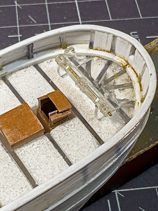
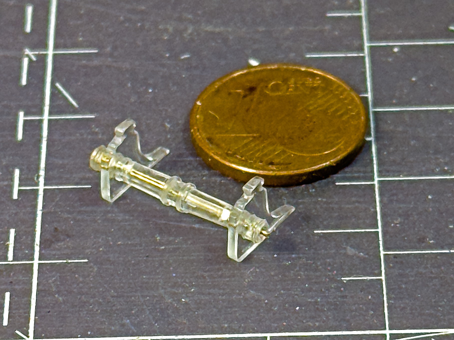
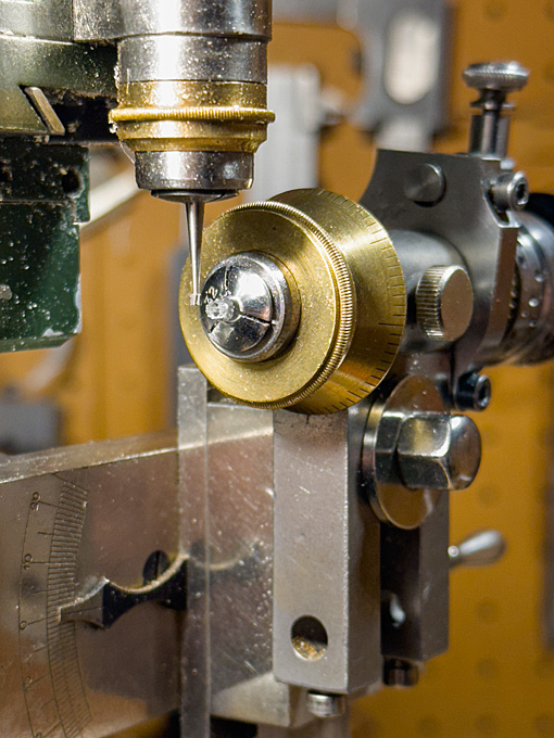
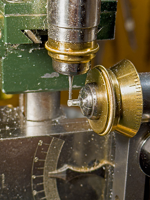
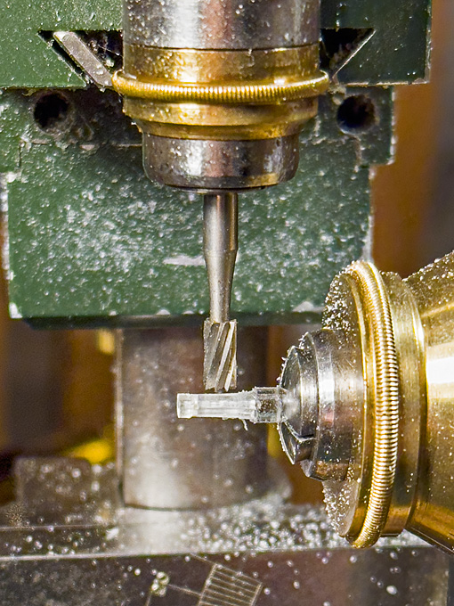
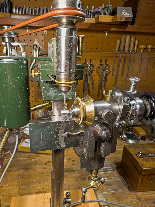
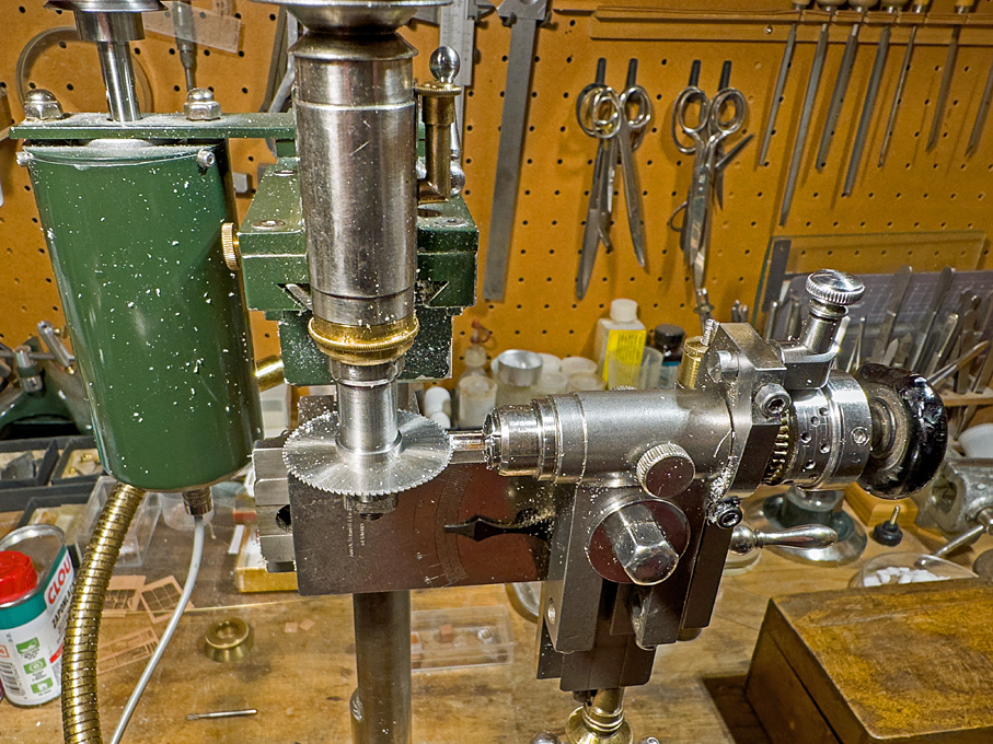
Thanks again for your interest ! ******************************** Anchor-winch 3 The winch drums were fashioned from 3 mm Ø round acrylic rod. Each side was built up from two pieces. The problem here were the square holes for the handle-bars. In principle, one could cross-drill two holes and file the square, but at 0.5 mm x 0.5 mm this would have been quite a challenge. There would be other options, such as broaching, but this requires specialised tools. The simplest thing is to divide the drum into two parts, to slot the end of one part, cement the two parts together and one ends up with perfect square holes. Set up for slotting the ends of the winch drums Slotting the winch drums To this end, a piece of rod was faced on both ends, and drilled 0.5 mm for the axle. It was then transferred to the dividing head on the micro-milling machine and the ends were slotted 0.5 mm deep with a 0.5 mm circular saw. Finally, a round disc of the same diameter was cemented to the end, leaving two perfectly square cross-holes. Milling the eight sides of the winch drums In the next step, the axle of the dividing head was tilted by 1.5° for milling the eight sides of the drum that is slightly conical. The drum is bound by iron hoops at both ends. These were generated by milling the drum to 0.2 mm diameter above the target dimensions. Then, the diameter was reduced by these 0.2 mm, leaving two ‘bands’ of 0.3 mm width and 0.1 mm thickness at both ends. Close-up view of milling the eight sides of the winch drums The thinner ends of the drum were faced off on the lathe to the correct length and then the drum halves parted off to the correct length. The spill-heads were done in the same way, but are cylindrical (or eight-sided prisms), rather than conical (or eight-sided truncated pyramids). A smaller burr had to be used, as the distance between the reinforcement bands is only 1 mm. Before parting-off, the outside ends were slightly dished with a round-burr in the lathe tailstock. Milling the spill heads For the ratchet wheel a short length of 3 mm acrylic rod was turned down to 0.1 mm above the target diameter of 2.0 mm. The geometry for milling the ratchets was worked out on the computer. I arrived at ten ratchets 0.2 mm deep (= 32 mm on the prototype, which appears reasonable). In watchmaking there are special ratchet-wheel milling cutters that can also cut curved teeth, but I don’t have any, so I had to make do with a dovetail burr, which is good enough, as the ratchet wheel does not need to be functional. Also, two 0,2 mm thick discs as flanges were parted off. Milling the ratchet wheel Unfortunately, these transparent parts are difficult to photograph and, indeed difficult to see during machining. A first coat of paint will eventually show any errors … The parts of the anchor winch made so far assembled The anchor winch at its future location To be continued …
-
If it's not too late: I would scrape off the moulding lines from the parts! Makes for a much more professional and realistic looking model.
-
hull finishing
wefalck replied to serpe's topic in Painting, finishing and weathering products and techniques
... exactly - this would be a sort of 'artisanal' model finish and not a realistic representation. On real ships neither brass nails nor varnish were used at that time. -
Dremel 4 inch table saw 588-2
wefalck replied to lynne's topic in Modeling tools and Workshop Equipment
Such pullies and teethed (or timinng) belts are standardised items and can be obtained via ebay or Amazon. Keep in mind that there are usually two types of pullies, with flanges and without. Normally a combination of both is used (as visible on the exploded diagram) - this evens out minor misalignments between the pullies. As you have a belt and know, where the motor and the saw-shaft are located, it should be easy to work out what pulley-diameter you need. From the exploded diagram above, it appears that there is a 1:2 reduction. -
If it tears, it is paper. Fabric doesn't tear. I have used both for some 40+ years now. From here on I show an example for the procedure I use: .
-
There is always a bit of confusion, whether silkspan refers to a fabric or silkpaper (both were used in the past to 'span' over model aircraft wings). For the fabric you can also look for the finest screen for silk-screen printing, say on ebay. For the paper you can look for the one that is used in book/manuscript restoring to double torn leaves. It is exremely thin and weighs only 7 g/m2. I got mine through a specialised on-line supplier.
-
This seems to be the old Revell plastic modell (built this way back around 1966 ...). The model seems to be missing the main yard, which at that time would have been involved in lifting out the launch as per the drawings from Harland. I believe HMS BEAGLE was also carrying two whaleboats in iron davits alongside her quarters. These whaleboats would have been very important as surfboats for landing on islands without harbours.
-
Haven't had time to look over this log for a while due to a lot of travelling. That's an interesting stoking system I haven't seen before and nice rendering of it 👍🏻 And also glad to hear that you seem to be out of the doldrums healthwise!
- 457 replies
-
- 4
-

-

-
- sternwheeler
- Hard Coal Navy
- (and 1 more)
-
Silence over the several weeks make one worry a bit in these disturbed days - however, high-quality sheet-metal work as usual!
-
N.B.: N-scale is 1/160 (1/150 in the UK) and 1/220 is Z-scale.
-
Anchor-winch 2 As planned, the drawings for the cheeks were printed to the correct size and stuck to a piece of 1 mm acrylic glass. A straight edge of the piece was used as reference surface. The first step was to drill the 0.5 mm hole for the axle of the winch-drum. This hole serves, together with the straight edge as reference for aligning the two cheeks so that they can be made identical. The drilling gives me the opportunity to show the watchmaker’s pillar drill (https://www.maritima-et-mechanika.org/tools/drills/drills.html) in action. Using the micro-mill as a router, the parts were roughened out with the aid of a fine cylindrical burr. Then a process of hand-filing began, using a variety of small and fine watchmaker’s files. The edges were slightly rounded using a three-sides scraper and a fine abrasive stick in the handheld electrical drill. Finally the parts were polished with a rotary bristle-brush. The lower edge of the cheeks is 9 mm long. Unfortunately, the transparent parts are difficult to photograph. To be continued …


-
The videos go about the boat-construction employed, but I was interested in how they convert the waste plastic into the structural material, on which I didn't find anything, neither on the YouTube-channel nor their Web-site. So I consulted my new friend ChatGPT and he came up with this: An amazing year of building ships from waste plastic! | C2A – YouTube Clean2Anywhere transforms plastic waste into boat-building material through a blend of low-tech and artisanal processes, combining traditional craftsmanship with modern recycling techniques: Collection & Sorting Volunteers—including their so-called “urban miners”—collect discarded HDPE plastics (like bottles, containers, packaging) and other waste streams. (Clean2Anywhere) Shredding, Washing & Melting The plastics are cleaned, shredded into flakes, then melted. This involves simple recycling steps akin to "shred, wash, melt"—an approach confirmed in projects like Flipflopi. (The Flipflopi, Squarespace) Molding & Extrusion into Lumber Molding: Melted plastic is poured into steel molds shaped to form structural components—planks, ribs, beams, knees—for the boats. (The Flipflopi, Artists & Climate Change) Extrusion: They also use extruders (even handheld ones with welding equipment provided by Leister) to produce consistent beams and boards from recycled HDPE. (LinkedIn) Assembly in Traditional Shell-First Method These molded plastic "lumber" pieces are assembled using 17th-century shipbuilding techniques: ribs and planks go together shell-first, held by welding and mechanical fasteners (nails or screws). (Ships of Scale) Welding Layers for Structural Integrity Larger parts are constructed by welding multiple plastic sheets or extrusions together to form thick, load-bearing hulls. (Facebook) In essence, they upcycle plastic waste into high-density structural "lumber", functioning like wood or composite beams—ready to be shaped, fastened, and assembled into seaworthy wooden-style boats. This process perfectly bridges recycled materials and traditional boatbuilding, enabling them to launch full-scale vessels like fluit ships, workboats, and even tiny houses. As an environmental scientist, a question arises immediately: what is the carbon- and energy-balance of this extruded material in comparison to wood? I also hope that they collect and recycle their own chippings
-
Indeed, for square or rectangular stock or excentric turning a independent 4-jaw-chuck is really useful.
-
Is there actually somewhere a description of the building processess? On the above Web-site there doesn't seem to be anything !?
-
These vertical boilers seem to have been very economical on coal (and space), which is one of the reasons they were used in various maritime and industrial applications. The volume of water was quite small, allowing to raise steam quickly (important e.g. for fire-engines and donkey-engines), but had little inertia and needed constant freshwater supply.
- 457 replies
-
- 6
-
-
- sternwheeler
- Hard Coal Navy
- (and 1 more)
-
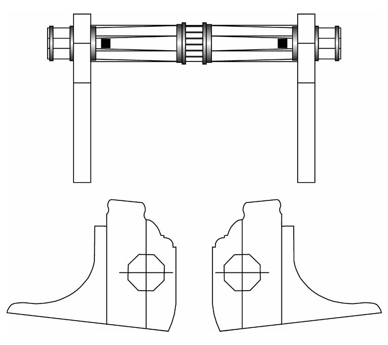
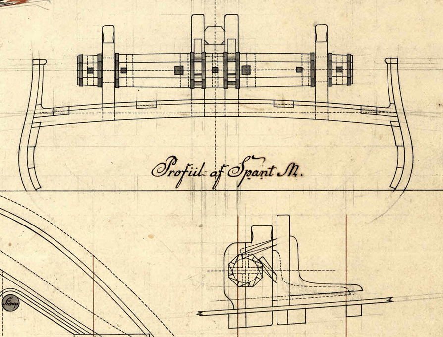
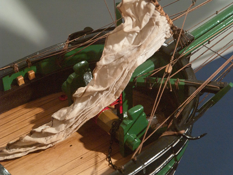
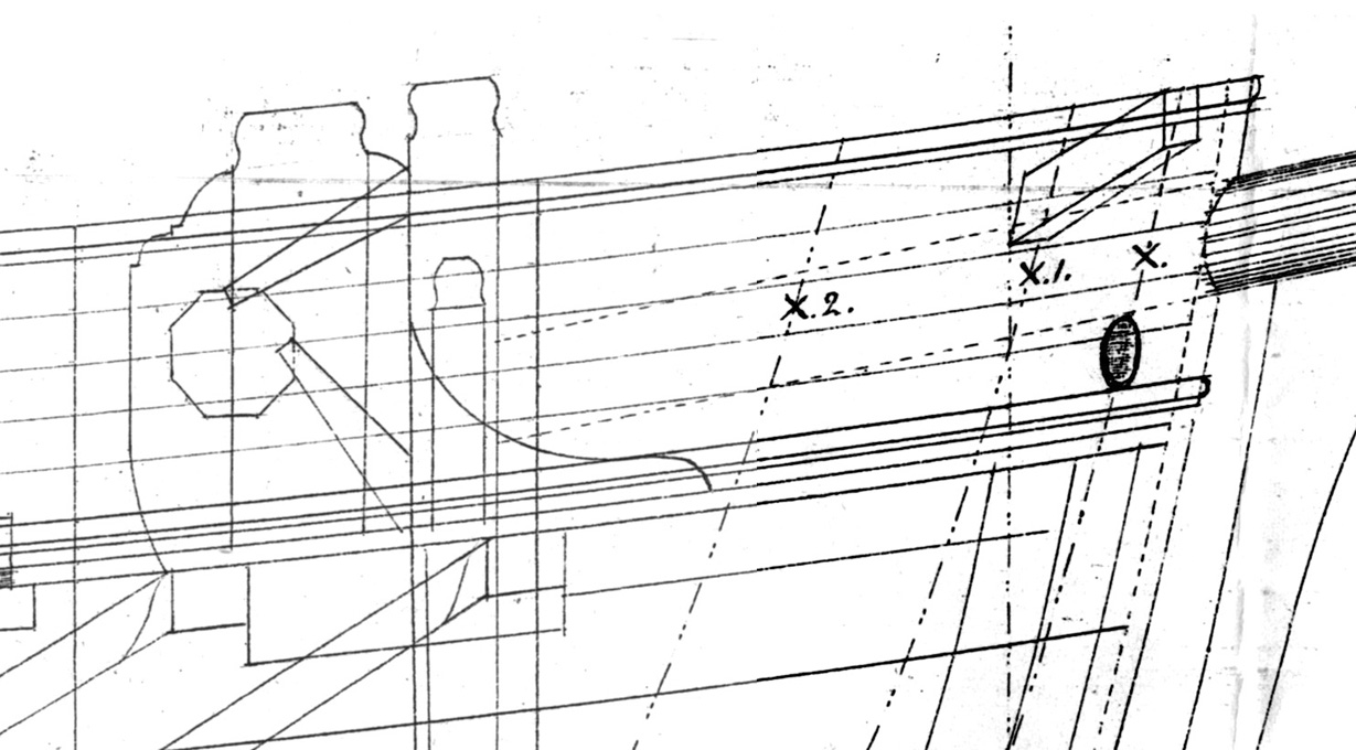
Thank you Pat ... Back from another travel, I turned my attention to the Anchor-winch 1 I spent quite a bit of time perusing contemporary drawings and near-contemporary models of small mid-19th century Baltic vessels in order to get a good idea of what, at that time, the anchor-winch of a modest small vessel might have looked like. While the archives of the Danish Royal Shipyard in Copenhagen indicate, that winches with mechanical advantage, such as those driven via gears and an idler-shaft or patent-winches seem to have been known by the mid-1830s, they don’t seem to have been common on more modest vessels. Vessels, such as this Rahschlup, were built in small shipyards with limited forging and other iron-working capabilities, let alone gear-cutting facilities. Gears could have been bought in, but this would have been too expensive probably for this kind of ‘subsistence’ shipping. Profile of the winch – Detail from the Original drawing by Möller. This research was needed, because the original drawings show the profile of the cheeks, but there is no plan view, that indicates the length and shape of the barrel. In the Danish archive I found the drawing of a single-masted jagt of comparable size with relatively detailed rendering of the winch. It may be a bit older than the Rahschlup, but the original drawings indicate an eight-sided barrel, which at that time was already a bit old-fashioned. Other drawings from the Danish archive of the mid-1840s showed already more modern looking round barrels. Jacht THETIS (1842) – Late 19th model from original drawings in the Altonaer Museum, Hamburg. The Danish drawings and various photographs from similar vessels under restauration confirmed that the cheeks were surprisingly thin, only about half a foot in thickness. Similarly, the post against which the bowsprit will rest was only ¾ of a foot in cross-section. Detail from a drawing F150-119 for a Jagt, Rigsarkivet Copenhague. Based on this information, I drew the barrel and the cheeks as working drawings. The drawings for the cheeks will be printed and stuck onto 1 mm acrylic glass as a guidance for sawing them out. Working drawing for the anchor-winch of the Rahschlup Workshop results coming hopefully soon …
-
There are several Web-sites specifically on the Taig and modifications etc. owners made. For instance this one: http://www.cartertools.com And yes, mounting the motor on some sort of hinge was/is common practice, even by manufacturers. One can make this more sophisticated by providing locking/tensioning screws. And yes again, removing the belt is good practices. Leaving it under tension may not stretch is, but may deform it in the way it has been put aside, leading to an uneven bumpy rund, at least initially. I don't know what you are planning to do with the independent 4-jaw-chuck, but its use may imply that you need to have a dial-indicator and a mount for it to be able to center workpieces.
-
It is always a good idea to hide the line between the background painting and the 3D-foreground with some 'props' such as trees, hedgrows, fences etc. I have seen in museum dioramas that the foreground (cliffs etc.) was continued as fading out relief into background. It is always difficult to convincingly continue a 3D-foreground feature into the background painting. There will be always a sharp edge between them. So it is better to have a clearly outlined feature in front of the background. Somehow, I have the feeling that the cliffs left and right continue as painting on the background - perhaps you can continue with the same style of painting as on the 3D-feature for a few inches and then let the cliff details become increasingly faded? Otherwise, it is coming on indeed very nicely ... I regret that I don't have the space for a railway model.
-
It turned out really well and convincing. I really like your approach of thorough research into the circumstances, function and the details 👍🏻 I think this deserves to be written up, say with a leaning on modelling in the NRG Journal and with a leaning on the research e.g. in the International Journal of Nautical Archaeology (which deals, unlike to what is suggested by the title also with recent and sub-recent vessels).
- 312 replies
-
- 5
-
-
-
- Chile
- Latin America
- (and 6 more)
-
Personally, I like to 'animate' my models, but then they are usually arranged as scenic display. In your case, a single figure for scale may be just the right thing.

