HOLIDAY DONATION DRIVE - SUPPORT MSW - DO YOUR PART TO KEEP THIS GREAT FORUM GOING! (Only 20 donations so far - C'mon guys!)
×


cookster
-
Posts
416 -
Joined
-
Last visited
Content Type
Profiles
Forums
Gallery
Events
Everything posted by cookster
-
HI Danny, I followed your Vulture build, although I missed the actual completion and had to go back and get caught up. She turned out beautiful! I will now follow your cross section. Your workmanship is outstanding, and I appreciate the way you show "how you did something", not just what you did.
-
Mobbsie, I don't deserve those flattering comments but thanks so much for your kind words!! I can tell you there's a whole lot more I don't know than I do know. I'm just hoping to learn all I can while on this journey and not screw up anymore than can be avoided. Thanks again!
-
Thanks Alan! I will try and trust the drawings first, that has been my method so far and for the most part it has served me well. Now that I have the tables I can verify, or improve the accuracy of, things I was before "guessing at". I received your book yesterday, I'm so glad i found out about it! It will help me tremendously. Thanks again for putting it together!
-
Hi all, I've been working on the hawse timbers Sorry, no additional pics yet. I'm now on version 3 of the hawse timbers and I'm struggling with them to be honest. Not the making them part, but drawing them and getting everything around them to line up. In a post above I described changing the number of cant frames to help alignment, I I had to do that a 3rd time. Not only the widths of the hawse timbers (which directly affect the spacing of the hawse holes) have been tricky to determine but the height of the hawse holes as well. I posted a topic over in the research section, I won't go into details here - if you'd like to take a look it's here: http://modelshipworld.com/index.php/topic/12746-usf-essex-1812-vertical-location-of-the-hawse-hole-question/ I was doing more research and I stumbled on Alan Yedlinky's scantling book. I had no idea that was out, so I ordered a copy and it arrived today. I plan to bury my nose in it and see what else I can learn that may help me (or confuse me more...) As soon as i have some real progress I'll post some pics. As always, thanks for looking in, hitting the like button or replying...
-
Hi Alan, I know this is now an old topic but I just found and ordered this book. I had no idea this was out there, I happened to stumble upon it while reading another's build log. I can't wait to get it, it should help me out tremendously on my Essex build. One question for you if you don't mind, how strictly would you think the colonial ship builders of the American Revolution period would've followed these "recommended practices"? I know it's said Hunt used the Scantlings of a 74 gun ship to layout the Constitution, and for Essex William Hacket is thought to have used scantlings for a 36 or 38. I'm just curious as to your opinion. Thanks!
-
Very interesting Ron, I'll have to check shapeways out.
-
HMS Naiad 1797 by albert - FINISHED - 1/48
cookster replied to albert's topic in - Build logs for subjects built 1751 - 1800
Albert, this is amazing! Wonderful! Outstanding! I have Ed T's book, watching you build her is fantastic. -
Siggi, I've been quietly following this build. Your skills and attention to even the smallest detail is inspiring - and impossible for most of us to achieve. Bravo Sir, bravo. You are a master craftsman! I will now go back in my dark corner and continue to marvel at your work.
-
Cutter Cheerful 1806 by rafine - FINISHED
cookster replied to rafine's topic in - Build logs for subjects built 1801 - 1850
She's looking awesome Bob! Have a great 2016!- 525 replies
-
- 3
-

-
- cheerful
- Syren Ship Model Company
- (and 1 more)
-
Man Tony, I go away for a while, come back and you've finished another one. Great job as always.... Have a great 2016, I'll be visiting you on your next build...
- 255 replies
-
- 4
-
-
- granado
- bomb ketch
- (and 2 more)
-
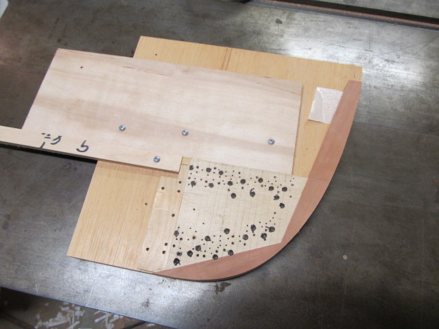
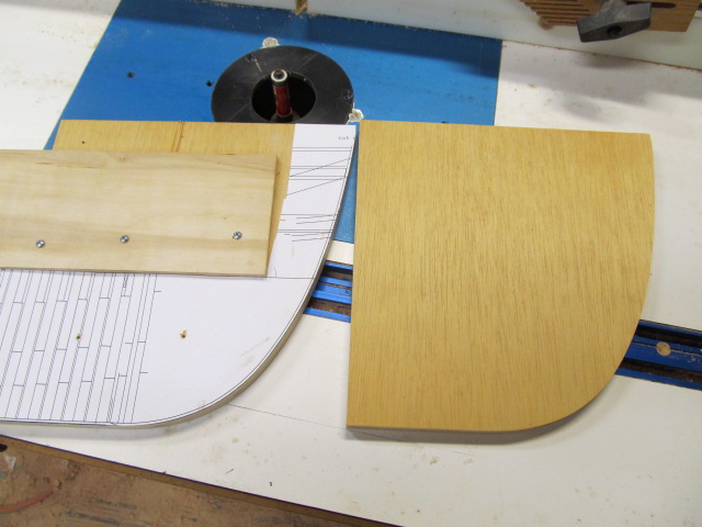
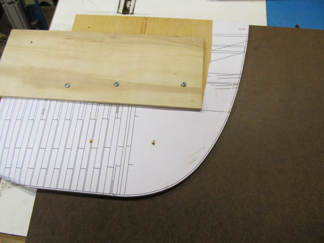
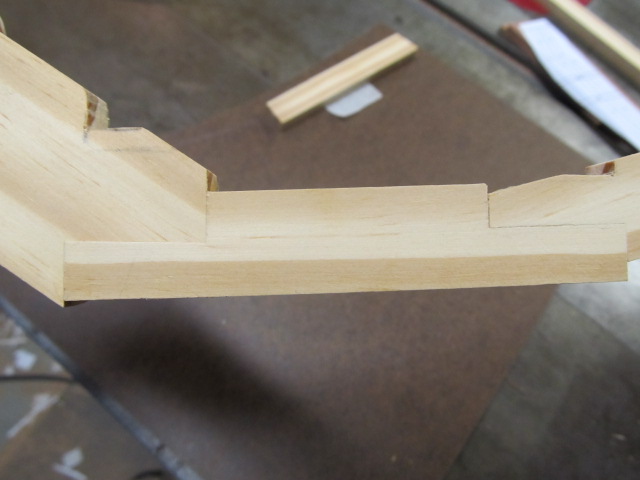
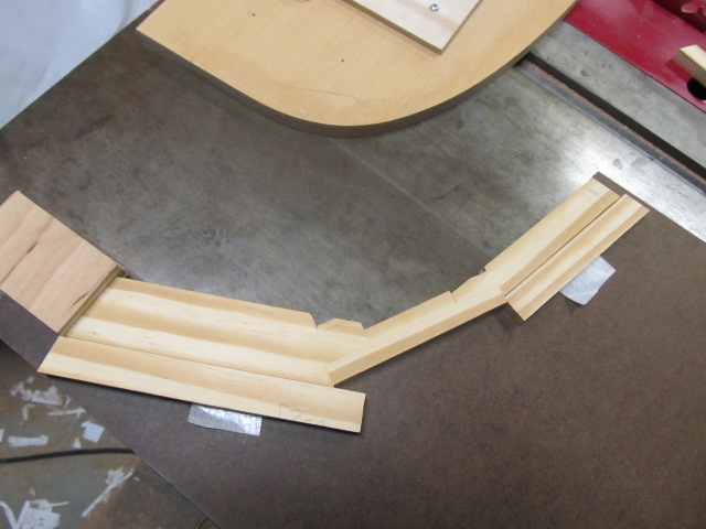
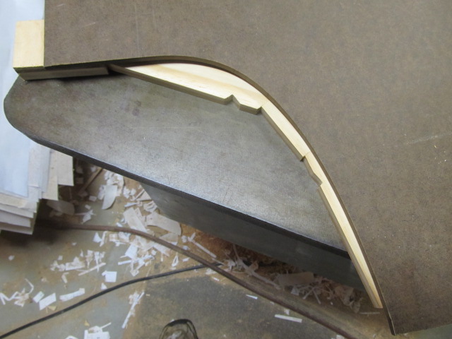
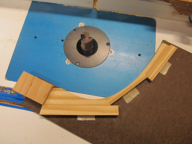
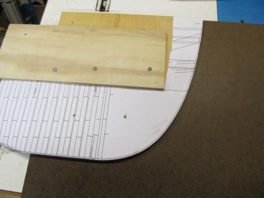
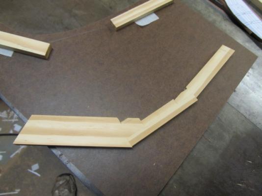
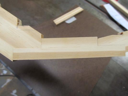
The same template process was used to rout the profile of the apron.

-
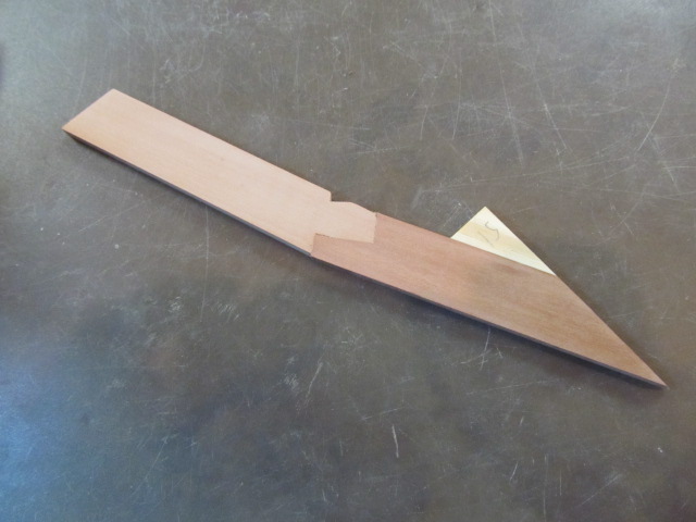
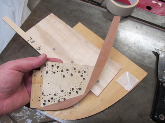
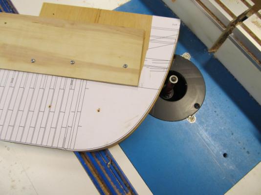
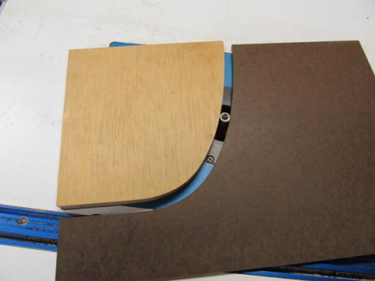
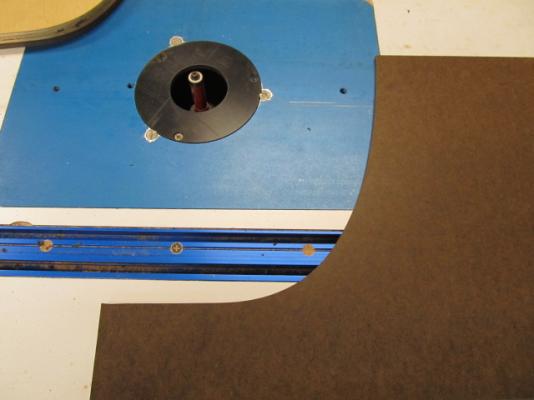
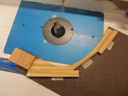
Here's how I plan on making the stem, a test piece was made from pine. I'm going to use template routing. To do this requires a template of the desired profile. I won't go into details on pattern routing, it would take much text to describe the process in detail and would bore 99% of you. Anyone interested can google "template routing" or "complimentary template routing" to see the process described in detail. I made a pattern of the stem's profile at the apron by sanding to a paper template. This pattern has to be made perfectly as it will be the master for all other templates needed. The I used the pattern to create negative pattern out of high quality hardboard.. The negative pattern has to be reduced by the diameter of the pattern router bit to be used. Here it fits the stem profile perfectly. The stem blank was made using scarph joints. Next, the stem blank was placed in the proper location on the template. Here's the back of the template. You can see the excess that will be routed away. And after routing. Later after installing onto the bulkhead the stem's thickness will be sanded down using another pattern so the knee of the head can be built up.


-
Thanks George! I was pretty confident I had the woodworking skills and design abilities (he says with all modesty!) I've been building and designing stuff, models included, since I was 6 years old. The problem I knew I'd have, and it's proven true, is lack of shipwright knowledge. There just so much I DON'T know. Before I started this project I'd never heard of "frame lofting". I couldn't have drawn an accurate ship frame if my life depended on it. There are people on this board who know 10 times more about framing and building wooden warships than I'll ever know. What I am good at is drafting (CAD helps more than can be stated) and designing "stuff. So I dug in and and started learning, and fell back on common sense when research failed to turn up what I needed. I hope to draw plans for another ship one day - I do enjoy it. And I've made plenty of STUPID mistakes. I've redrawn those damn cant frames more than I want to admit while making several versions of them, mostly because of not fully understanding the various lines on 200 year old plans OR, trying to force the lines on the original draft to fit something when in the real world the needed "line" was staring me in the face - but refusing to believe it. At least they finally fit now. A lot of what I've drawn is based on well informed (I hope) guesses. Others, here's a prime example, is needing to add 2 more cant frames. I have no idea if that's correct or accurate, but based on what I have now - it's a course I must take. I drew out the added 2 cant frames and everything i was struggling to fit fell right in place. So that's an easy "guess" for me. In the end when this is all done and finished if I can say to myself I did everything I was capable of doing in both research and intelligent guessing - then I'll be happy. I hope. Thanks again for looking in!
-
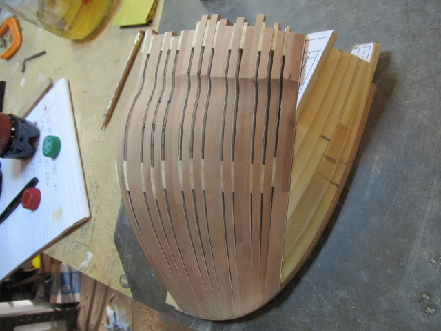
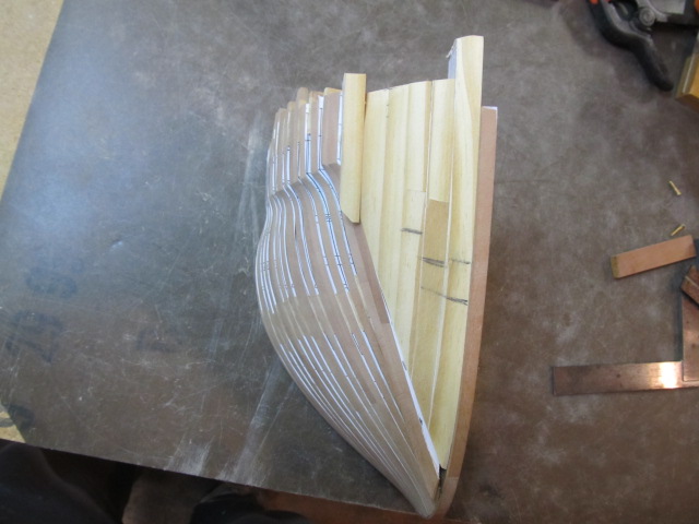
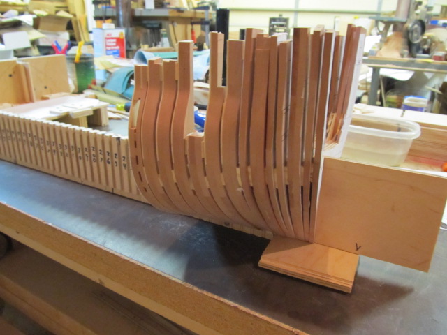
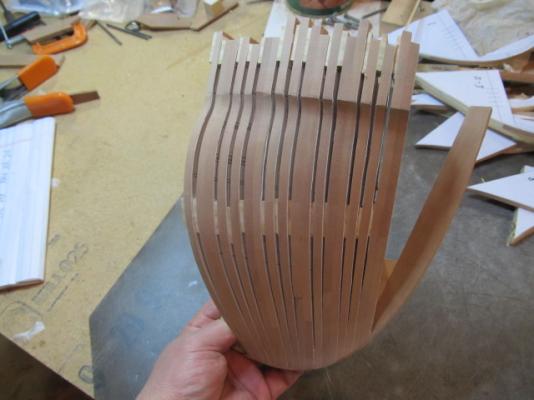
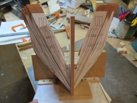
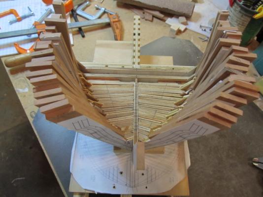
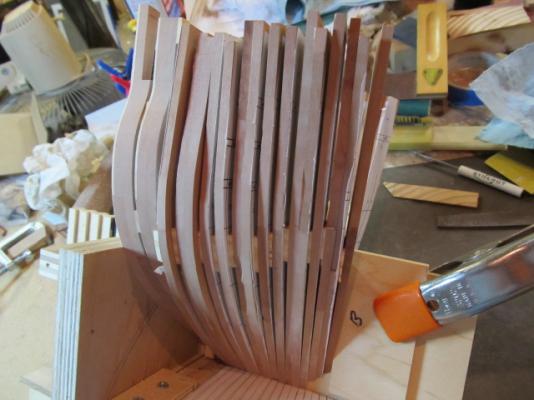
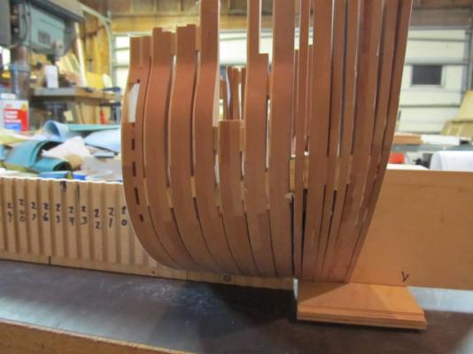
hi all, back for an update. First, I hope all had a Merry Christmas and here's wishing all of you a happy new year! Here's where I'm at currently. I'm shaping the cant frames and working on the hawse timbers. I made a test run of the hawse timbers out of pine to get a feel for making them. It's become apparent I need 2 more cant frames. Without them there's too much space that needs to be filled with hawse timbers. I used Portia T's plan as a guide for laying out the cants, but I see now I need to add 2 more. Once I do that then 4 hawse timbers will work- instead of the 5 I have now. That also lets the hawse holes line up in the correct place. Also, I will go back and mill out the air space between the hawse timbers once I get them shaped. The pine is a good test sample for practicing doing that on the mill. That and drilling the hawse holes, Still a lot more shaping to do, but it's getting there. Pics


-
Damn nice work Mobbsie! I also have to admit I'm going to steal your razor blade scraper holder idea. I've used that type of scraper for 30 years and would've never thought of using it as you did - to hold a razor while shaping the rail. Brilliant...
- 255 replies
-
- 2
-
-
- granado
- bomb ketch
- (and 2 more)
-
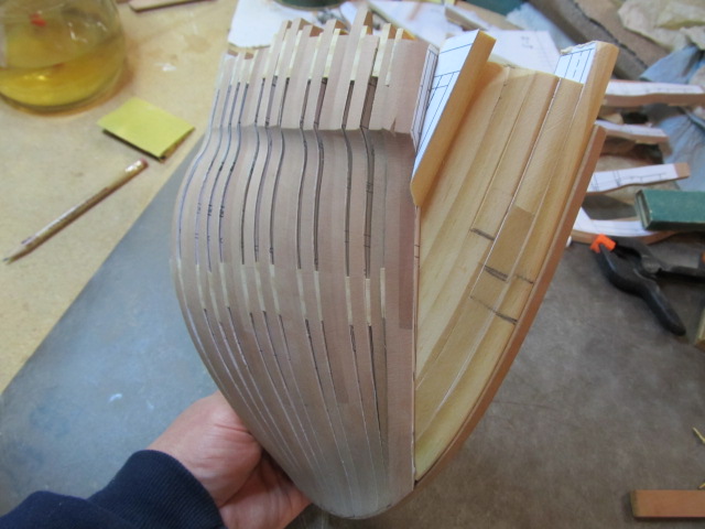
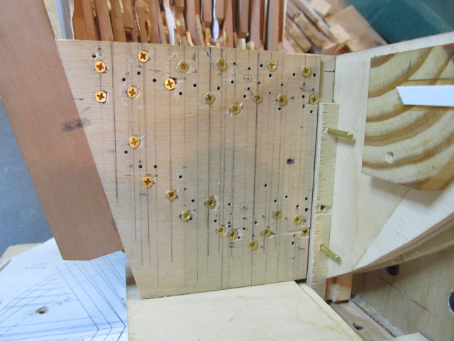
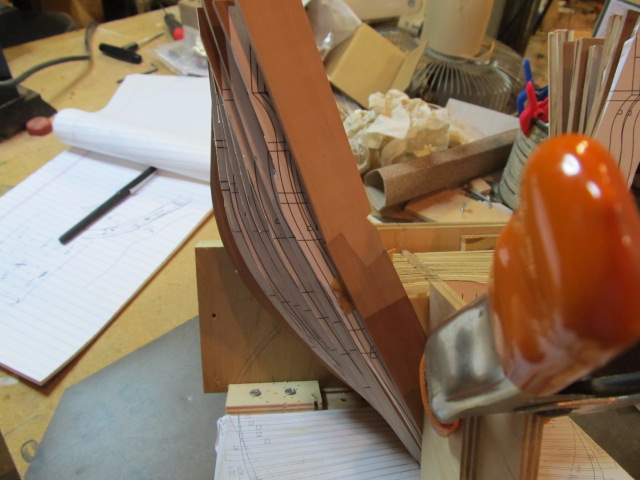
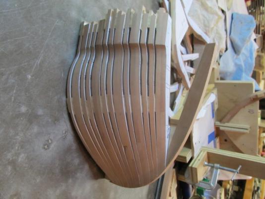
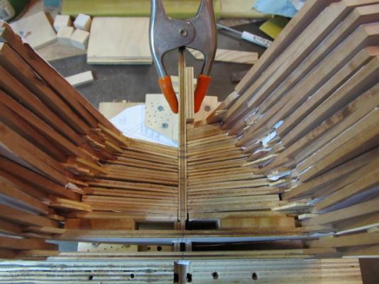
All the Cant frames are made now. They're all pinned with brass pins for alignment, and I've screwed the frames to the bulkhead. This allows me to remove and reinstall and keep alignment. I also added a piece to form the apron that sill needs to be trimmed. In the beginning I'd planned for the area at the rabbet to be planked over, but now I'm thinking I'm going to be able to have it show so I need to add some pear in place of the plywood since it would be visible. I also pinned the bulkhead extension to the main bulkhead to hold it in place (in this pic it's on the temporary bulkhead) and added truss rods through the cant frames on each side to hold them tightly to the square frames. Next some shaping and the stem. As always thanks to everyone for the likes and for looking in.


-
Cutter Cheerful 1806 by rafine - FINISHED
cookster replied to rafine's topic in - Build logs for subjects built 1801 - 1850
Looks good Bob! 1300 holes drilled by hand? 1300 more to do again? You're more man than me. I'd definitely be reaching for a rotary tool of some type...- 525 replies
-
- 3
-
-
- cheerful
- Syren Ship Model Company
- (and 1 more)
-
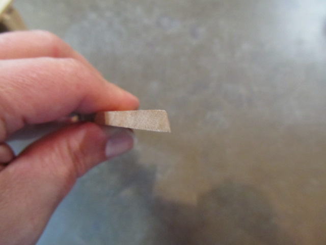
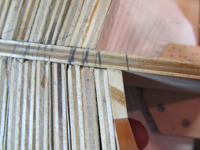
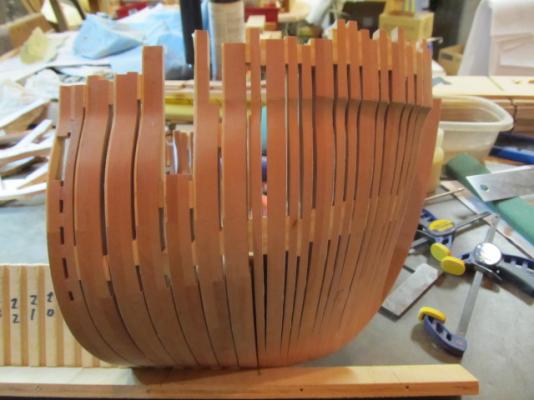
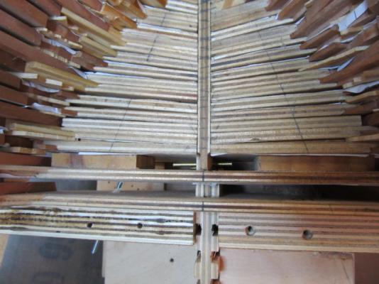
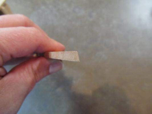
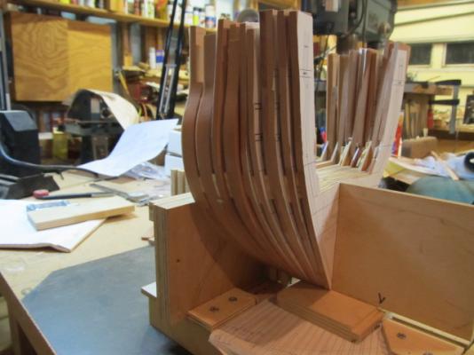
More Cant frames made. Using the mill for the scarph joints is working out fine I'm beveling each frame where it goes against the center bulkhead, just as it would if this were a conventional deadwood joint. The frame looks like it's beveled, but it's an optical illusion. Here's a close up of the top of the plywood "frames" against the center bulkhead. And a few more in positon Won't be long before I'll have to start on the stem and apron, and the hawse timbers/Knight Heads.


-
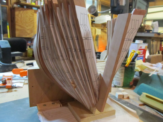
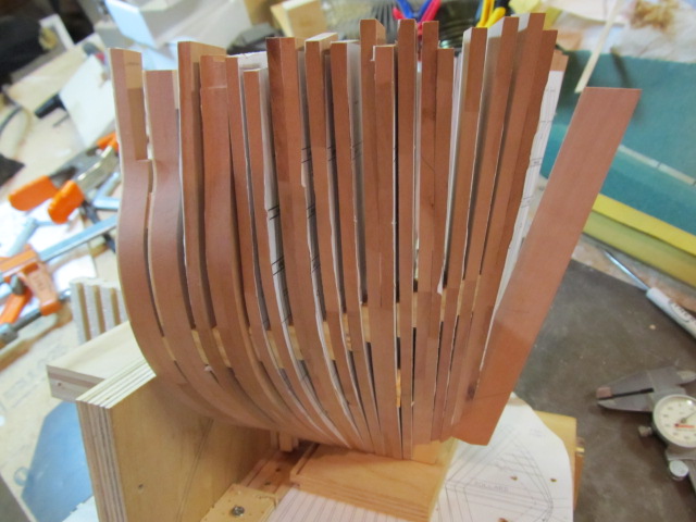
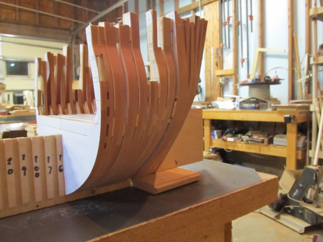
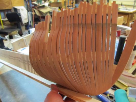
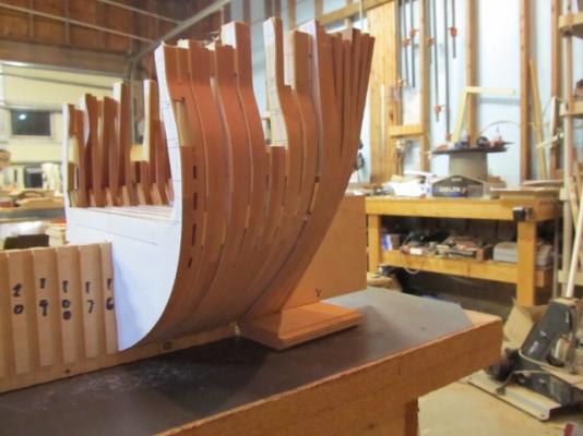
I've added a few more cant frames now that I'm over "Cant frame builder's block". Here's how it looks when added to the center bulkhead section and square frames. The cant frames are only rough shaped, the tops aren't shaped at all but you can get somewhat of an idea of the bow of a ship.

-
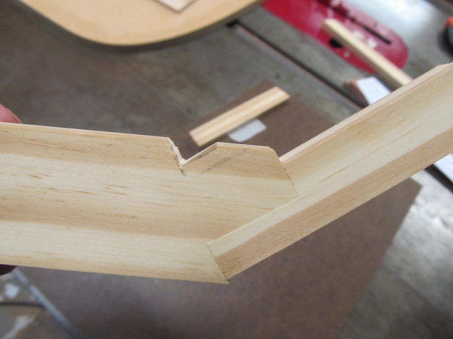
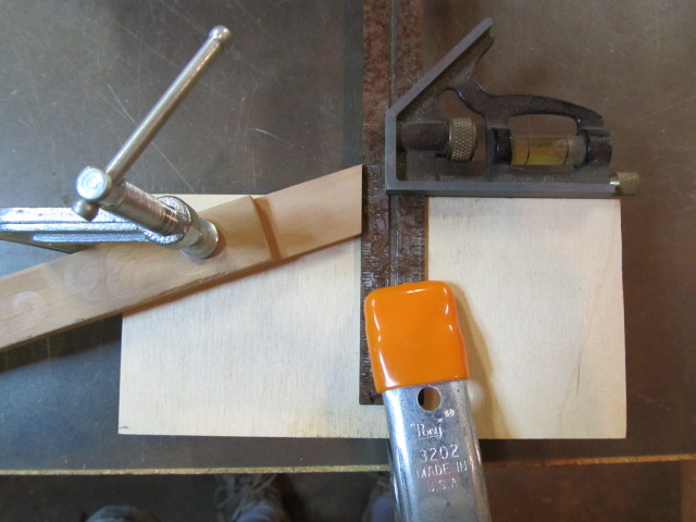
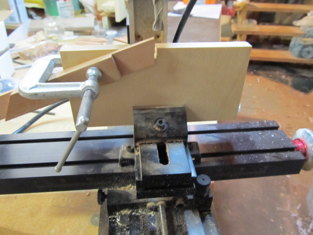
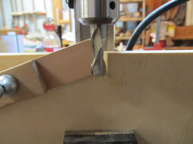
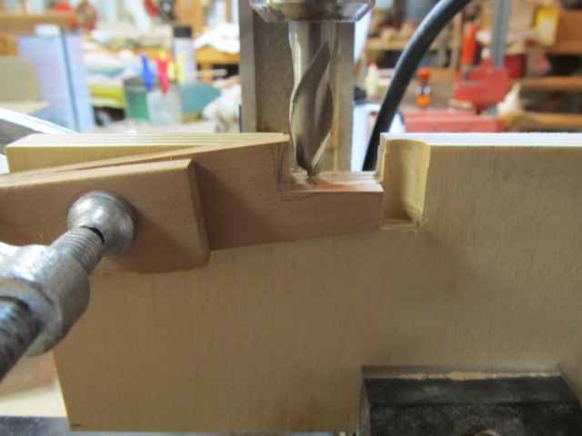
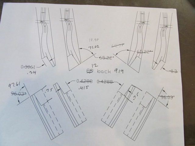
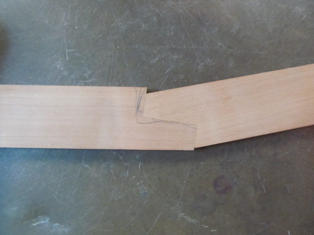
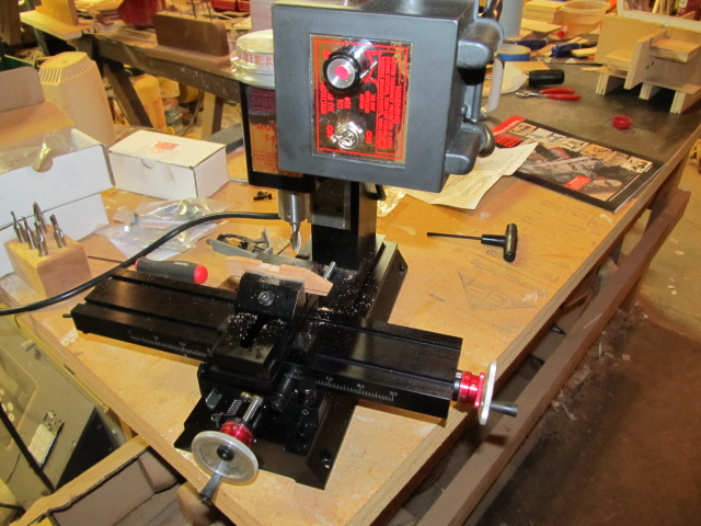
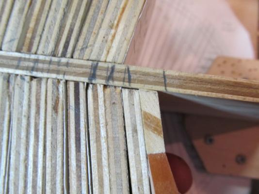
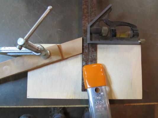
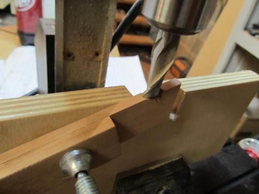
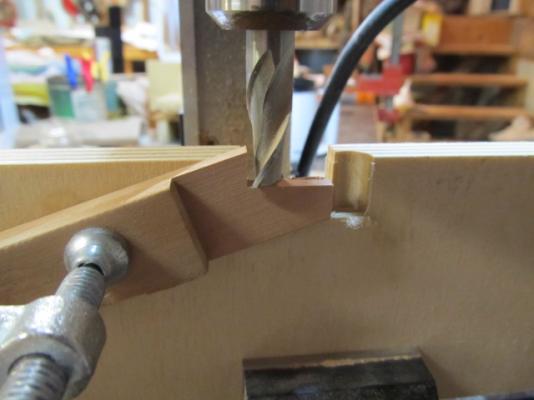
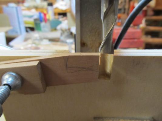
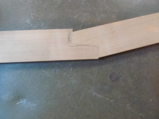
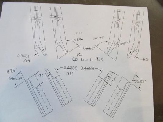
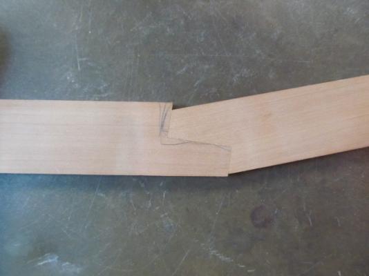
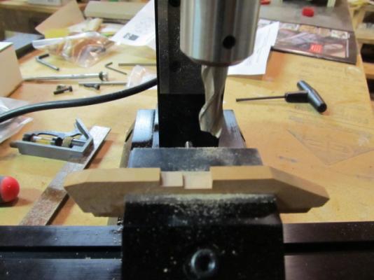
I thought I'd briefly show how I milled the scarph joints using my Sherline mill. This is my first milling project so it took me a little time to wrap my head around it. When I first started thinking about how to do this I drew a blank. I didn't want to use paper patterns or layout lines to do so, it seemed to me that would defeat the accuracy of the mill. Here's a dwg of the measurements for this joint on this particular frame. I tried to think of ways to use the accuracy of the mill to my advantage, and then it hit me. First, I cut the angle needed on the end of the piece in the chop saw. I will use this angle to locate, then clamp the stock in place in a jig. I realize using a square (even this accurate starret square) is not as accurate as a machinist would use, but for this it works fine - so far. And as far as the jig, a piece of plywood will do until I decide how to build a "real" jig. Then I mounted this setup in the mill vise. First, I faced off the end of the stock a few thousandths to get an accurate zero point. My first test on my process yielded less that accurate results from just guessing at zero, so facing off allows me to get a "perfect" zero start point. Then I moved the slide over the exact amount of the width of the scarph, in this case .750". Then I moved the bit down until it just contacted the stock, this point became my zero for height. Then, using the measurements for the depth and length of the scarph, I milled the waste out. Next, the same process was repeated for the other piece. And here's the completed joint. I'm pleased with the results. Joints are nice and tight and accurate, and best of all no patterns, layout lines or guestimating was needed!


-
I've been using my mill for a couple days now and so far I love it. I hated cutting those scarph joints the way I was doing it, to the point I almost gave up on making them. With the mill they are so much easier, and much more accurate. Here's one I cut today. Now I don't mind making them....
-
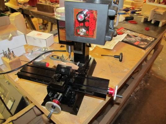
Ahhh, new toy is set up and I made my first cut in some scrap. It works! Now I gotta find some scarph joints to cut...
-
Mobbsie, your comments are flattering, thanks so much. I'm not sure if I deserve them though. And yes, I can see where this is going in my minds eye, I just wish I could communicate it to others without 1000 word essays (that don't help). I know 9 out of 10 still don't have a clue what I'm doing. Hopefully someday it will become apparent... Oh, and don't sell yourself short either, remember that "little" Agamemnon boat you built? She's a beaut mate and I just hope I get close on anything I build. Augie, I almost found myself doing just that - cutting corners and quality just to speed up and finish something. I had to step away before I actually did it. Kmart, thanks. I'll get back to my Connie at some point, I'm ashamed to admit I got kind'a bored with her. I see her sitting almost everyday just waiting for attention...
-
Augie, those last few pics are the "Cats Meow". Really stunning, Awesome pics of an awesome model!
- 2,191 replies
-
- 4
-
-
- confederacy
- Model Shipways
- (and 1 more)