HOLIDAY DONATION DRIVE - SUPPORT MSW - DO YOUR PART TO KEEP THIS GREAT FORUM GOING! (89 donations so far out of 49,000 members - C'mon guys!)
×


EdT
-
Posts
2,214 -
Joined
-
Last visited
Content Type
Profiles
Forums
Gallery
Events
Everything posted by EdT
-
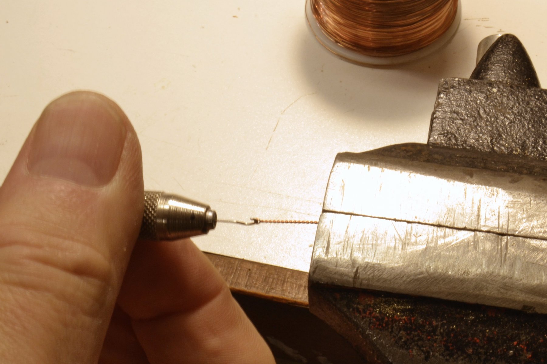
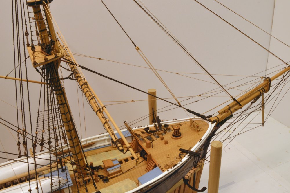
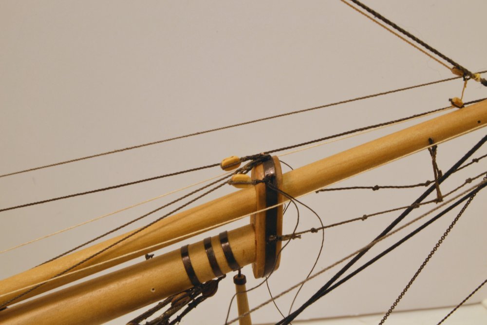
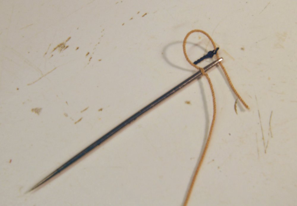
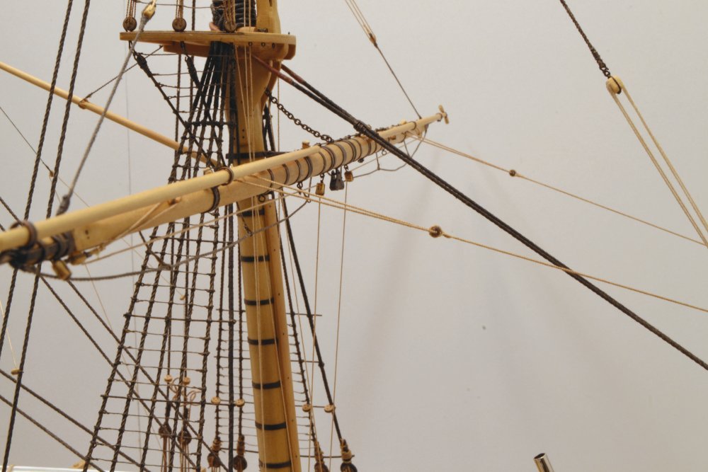
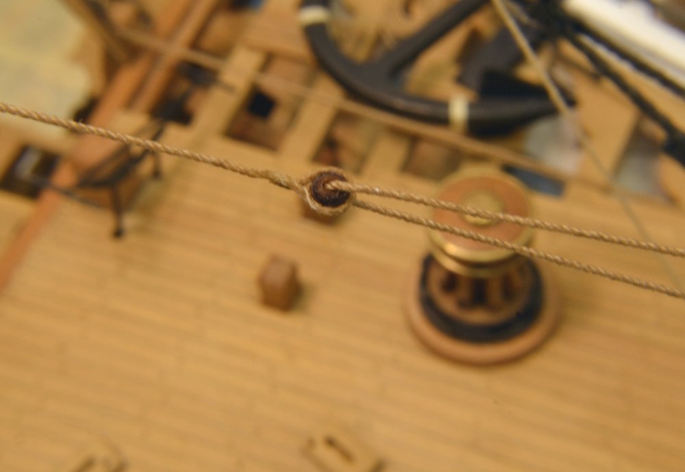
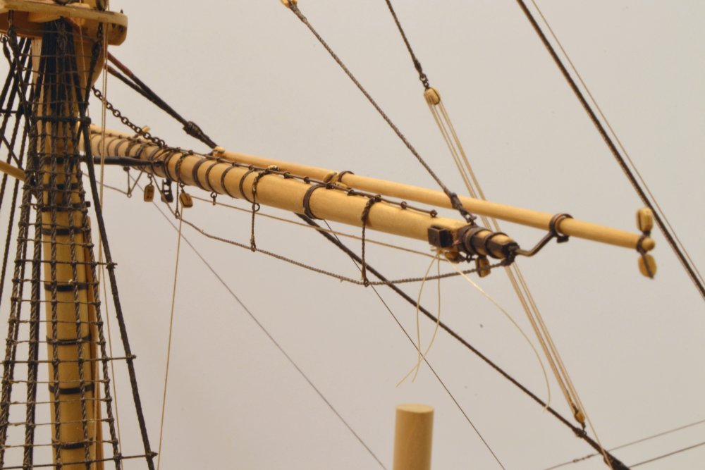
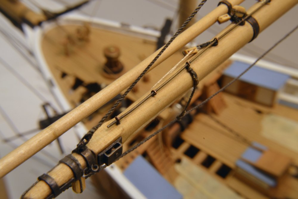
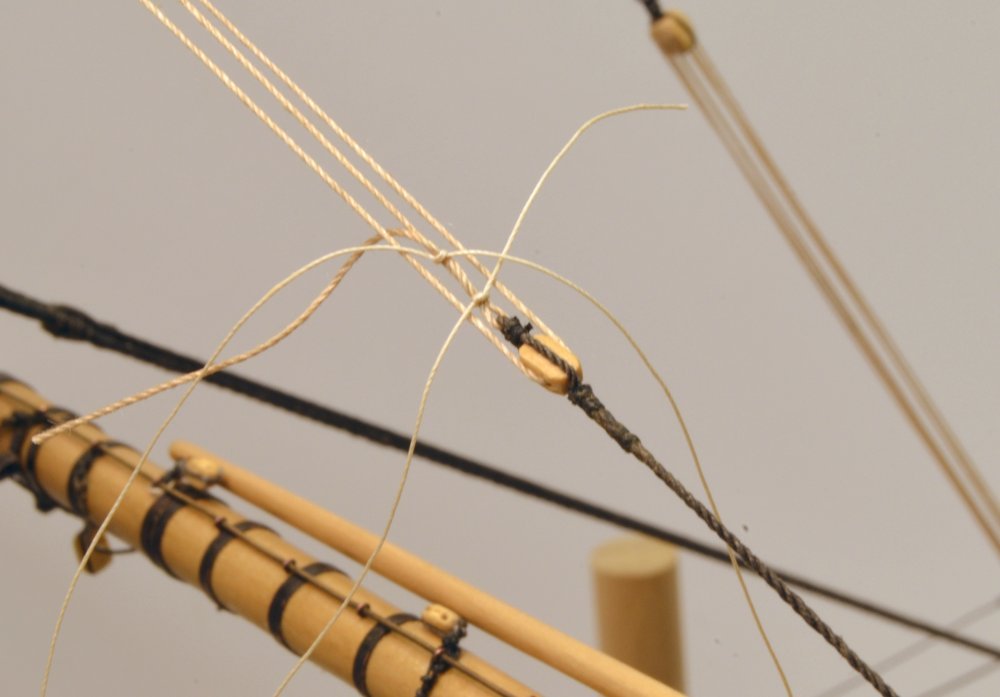
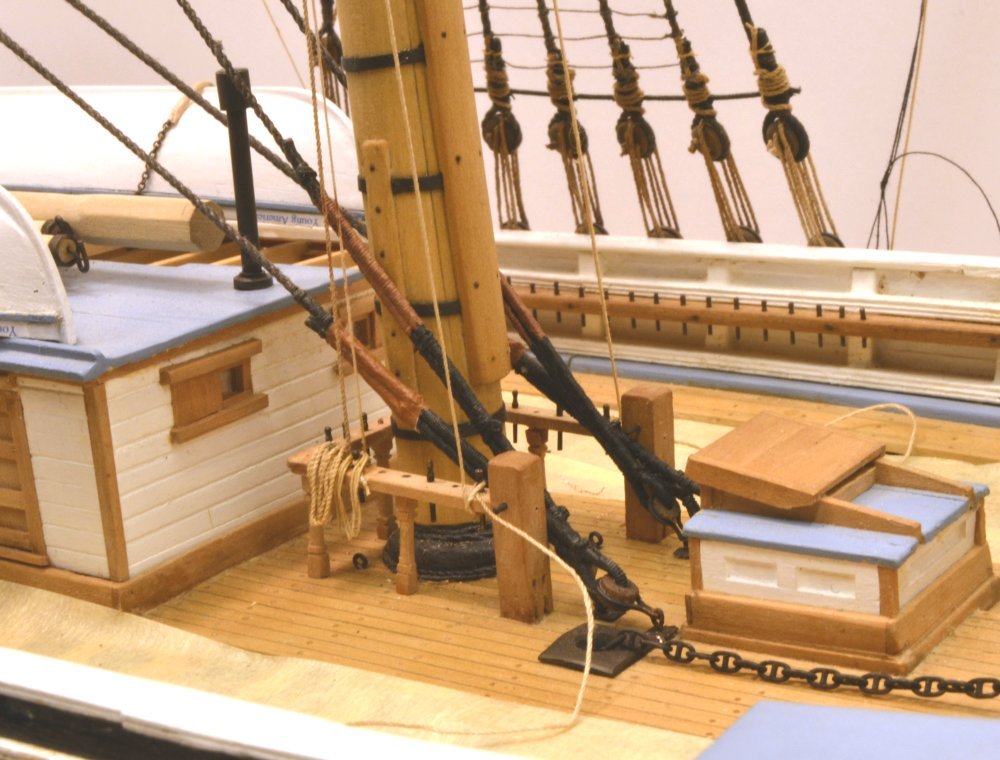
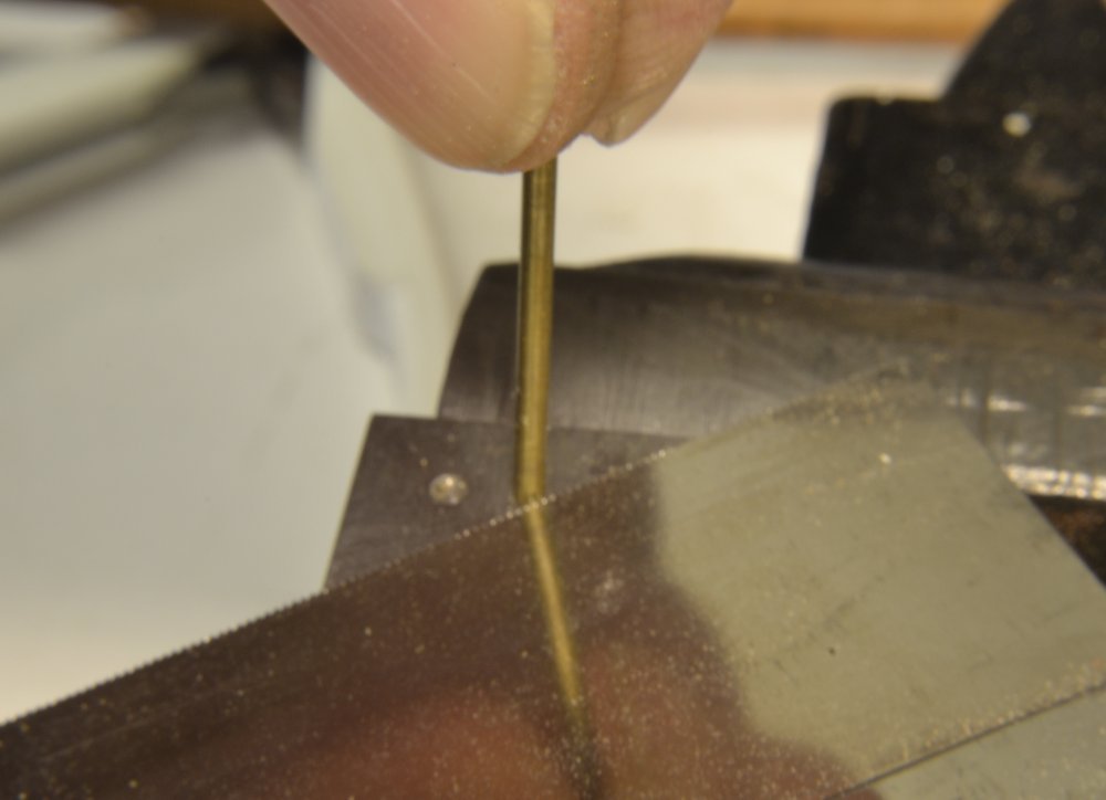
Young America - extreme clipper 1853 Part 257 – Fore Yard Bowlines Bowlines were used to keep the weather leech on large sails taut when close hauled – to prevent the sail from folding back on itself. On double topsail rigs they seem to have been used only on lower sails. The lines were toggled or tied to cringles about halfway down the leeches on each side of the sail using "bridles" that were brought together to a "lizard" that in turn was connected to the bowline itself. This consisted of a sort of whip tackle. Bowline bridles were toggled or tied to the sail after it was bent to the yard before it was loosed, so on the unsailed model the bridles are stopped to the jackstays with temporary knots. The first picture shows the installed bowlines. The bridles are passed through bullseyes on the lizards and tied off to jackstay stanchions. The standing ends of the tackles are shackled to eyes in the bowsprit, passed through the forward lizard bullseyes, passed through blocks lashed to the bowsprit cap, and belated on the forecastle fife rail. The next picture shows the two blocks being lashed to the cap eyebolts. The next picture shows the method I use to form most eye splices to shackles. The needle is passed into the rope, then the short end is threaded through the eyebolt shackle and needle, then pulled through and glued. The next picture shows the shackled eyebolt installed in the side of the bowsprit just aft of the bands. The picture also shows the bowlines rigged through the blocks. The next picture shows lizard bullseyes and the bridles. The bridle eyes are tied off to jackstay stanchions using small hemp knots. Then, a close-up of one of the bullseyes. The splice around the bullseyes were made as described above. As with other running rigging on the fore yard, the falls were belayed without glue to allow for later adjustment of tension or sag. Ed
- 3,618 replies
-
- 26
-

-
- young america
- clipper
- (and 1 more)
-
Mark, I'm not sure about your first sentence, or maybe it was me in my note, but in the winter the low humidity dries the rope and causes it to lengthen. Wefalck, I have to digest your rope shrinkage explanation, but I'm sure its credible. One other explanation for some doors sticking in winter is the effect of frost lifting thresholds on doors on grade. I have one such. Ed Later: Got it Wefalck. As the fibers swell, the circumference increases requiring more strand length to maintain rope length. That is, after all, what you said. Thanks.
- 3,618 replies
-
- 2
-
-
- young america
- clipper
- (and 1 more)
-
Thanks, again, everyone. I can't say how much your comments and support are appreciated. Steve, thanks for you interest in Volume III. I am very excited about it and hoping to make it a good reference on clipper ship rigging. There is much work to do, however. Carl, relative humidity where I live ranges from above 90% in summer months to as low as about 20% on the coldest winter days and it may persist at these levels for weeks at a time. I know my basement workshop hits these extremes - even with dehumidification in the summer. The contraction of rope (or model rigging line) when damp seems counter-intuitive, but I am assured by my prime sources that this is indeed the case, to the point where many running rigging lines were slackened during wet weather to prevent damage. (Luce, Seamanship 1868) Well-tarred standing rigging was probably less susceptible. I was very surprised a couple weeks ago to see considerable slackness had developed in the stays, backstays, and shrouds. I have withheld waxing the lines until attachments that involve gluing have been completed - items like ratlines, fairleads, and strapped blocks - and I am sure this has contributed to the amount of expansion. Some of the lines on this model are quite long. I expect to have better protected the rigging before the humidity of next summer creeps in, but also intend to keep an eye on things as the weather warms in the spring.
- 3,618 replies
-
- 4
-
-
- young america
- clipper
- (and 1 more)
-
Thanks for the thought, Micheal. The importance may not translate. My impression is that the topping lifts were used most usually at dockside or perhaps when moored. There would be no need that I could see - as well as some major difficulties with the yards above - to top the lower yards while underway. This relative unimportance is one factor in my thinking about belaying them further aft. Of course, by the time all the lines on this mast, maybe 100+, are rigged there may be a lot of crossed lines, although many will pass through fairleads in the top or on the shrouds. We'll see. I spent my two hours today unwrapping lower shroud lanyards so I can pull up on the shroud and backstay tension. The cold weather and lower humidity has loosened things up. Ed
- 3,618 replies
-
- 4
-
-
- young america
- clipper
- (and 1 more)
-
Thanks, everyone. I appreciate the comments and likes. Alan, the yard-holding fixture is a work in progress that I am sure will go through some further iterations before it is ready to describe or recommend to others. So far, I like its strength, portability and the multiple holes in the base for different-sized spars and perhaps different types of clamps, but the clamps shown need improvement. I only have about an hour invested in this so far. Mark and Micheal, thanks for the comment on the explanations. Considering the amount of detail to digest in putting the model rigging configuration together, these are pretty summary descriptions, but I am starting to believe that understanding function is essential to designing model rigging and at the very least interesting to those who model it. I am not a sailor and certainly no expert, so the journey through the sources has been an arduous one. It seems that the least that I can do is share some of this - so I really appreciate your comments. The complexity of this is far from addressed in my short explanations. As an example, if you look at the photo of the fore fife rails in the last post, you will see the crossing of lines from above. So far, all my sources agree that the topping lift falls should be belayed on the foremost pins on each side, but those lines are aft of the yard while the line on the third pin and its soon-to-be-added neighbors are forward of it - directly under the center of the yard. This doesn't seem right, and the issue may be trivial, but I continue to search for a reason to change it, dragging in more sources that not only help with this, but often introduce new questions. It can be exhausting. Ed
- 3,618 replies
-
- 9
-
-
- young america
- clipper
- (and 1 more)
-
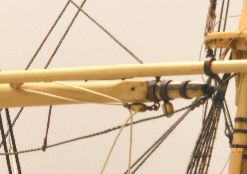
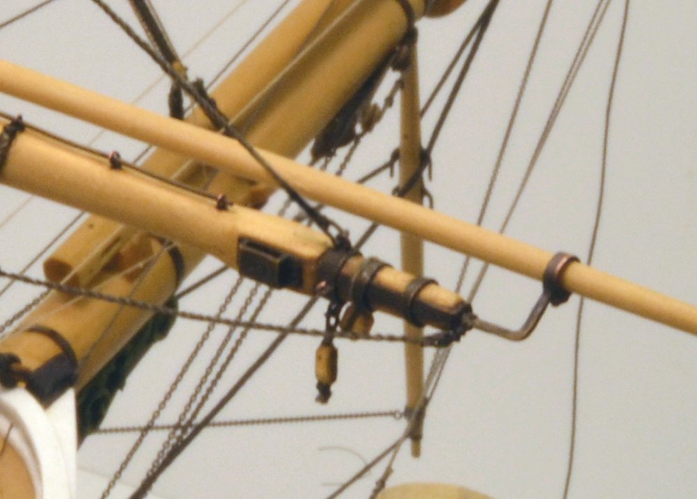
Young America - extreme clipper 1853 Part 256 – Fore Yard Reef Tackle The effective area of most sails could be reduced by "reefing," that is, taking in sail to diminish its size while set. Larger square sails, except for lower topsails, were equipped for this purpose with horizontal canvas reinforcing bands across the sail. These "reef bands" were fitted with "reef points", short lengths of rope to tie up the reefed part of the sail. To assist in bringing the reef band up to the yard, reef tackle was attached to the yard arm and to "cringles" on the leech of the sail just below the reef bands. This was normally a simple "gun tackle" (two single blocks) with a runner through a sheave on the double quarter block running down to a pin on the fore mast fife rail. When sails were removed (unbent), the cringle block would be tied off (stopped) to the jackstay. When the sail was again bent to the yard, this tackle would be attached to its "ear-ring" and used to stretch it out to the ends. It would then be re-connected to the reef cringle. The first picture shows the reef tackle fall running below the yard and through the quarter block. The next picture shows the yard arm tackle block shackled to the lower eyebolt on the band. In this picture the seizing to the block has not yet been tied, nor has the fall been taken inboard to the quarter block. The cringle block is just visible below the boom. The next picture shows both tackles rigged. In the next picture the port fall is being belayed to the third pin on the fife rail. As with other lines at this stage, no glue is used (yet), allowing further adjustment once the yard is secured at final height (next part). The next picture shows the completed tackle under the port yard arm. The last picture shows the cringle block stopped to a jackstay stanchion. I plan to replace the permanent-style black lashing shown here with a more temporary hemp stopper knot. This picture also shows the type of lashing used on the foot rope stirrups, the shackled attachment of the lift pendant, and some other blocks. The block at the lower left is the halyard block for the lower studding sail yard and will not be rigged. This block is strapped around the yard arm, simulating a lashed eye attachment. The eye on the aft side of the band will connect the brace pendant, and the iron cheek block will pass the soon-to-be-installed lower topsail sheet chain. Ed
- 3,618 replies
-
- 28
-
-
- young america
- clipper
- (and 1 more)
-
Douglas, the vertical supports are actually 1/2" dowels with slot cut out of the centers and the pins are actually screws for tightening to grip the yard. The design of these pins needs some improvement, but it worked well for this large yard. Ed
-
Thank you all, and thank you, Micheal for the idea. I can see I am going to have to have a good solution for this problem. All these suggestions have given ideas. Ed
- 3,618 replies
-
- 4
-
-
- young america
- clipper
- (and 1 more)
-
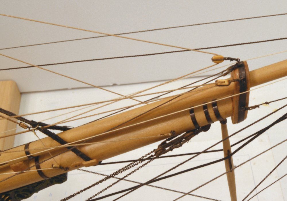
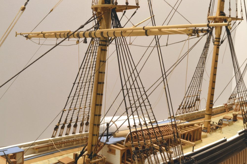
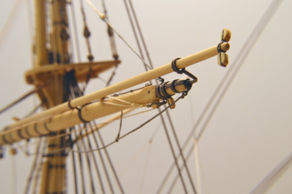
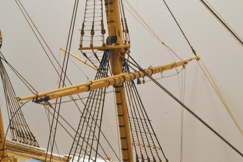
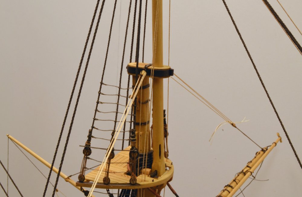
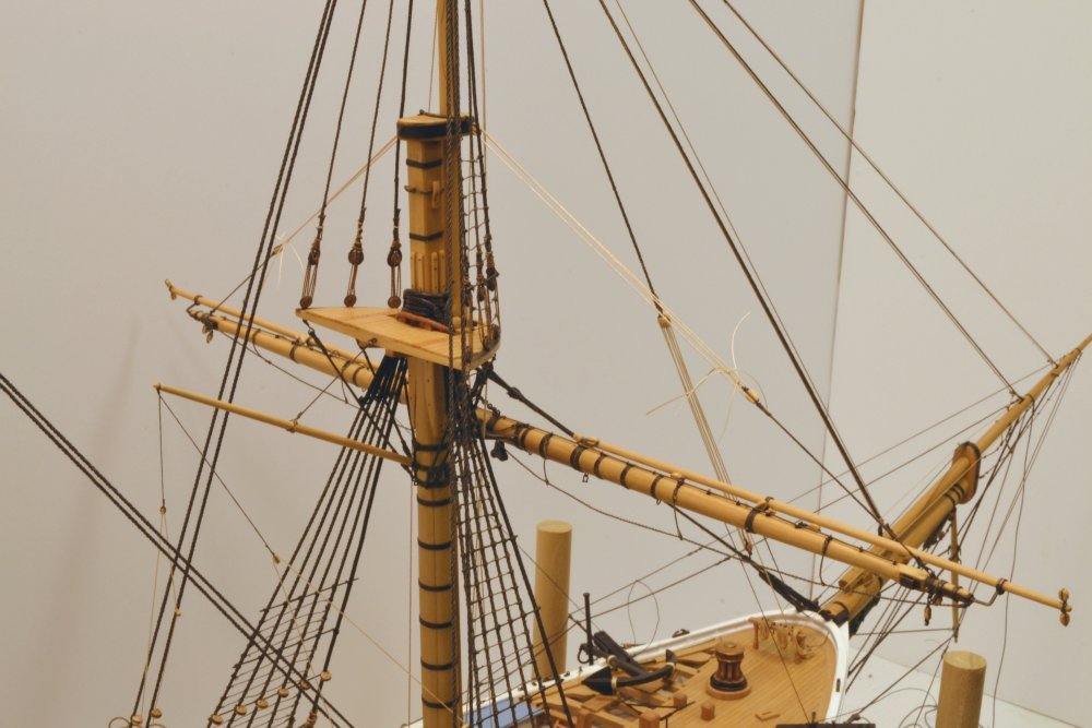
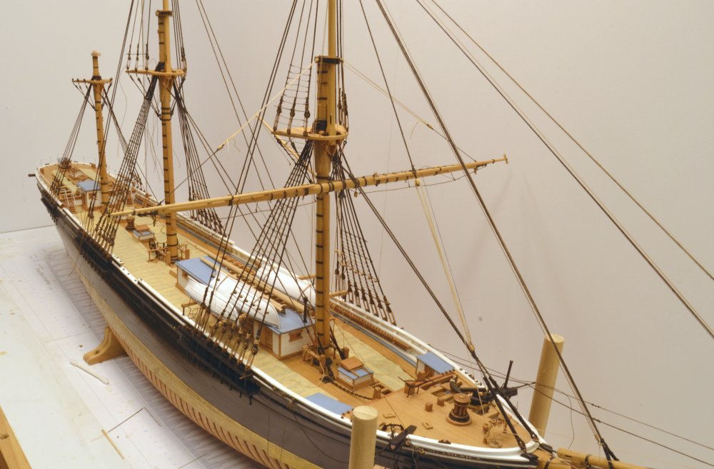
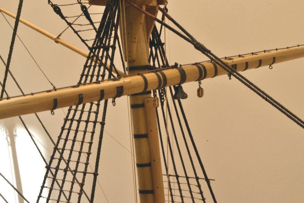
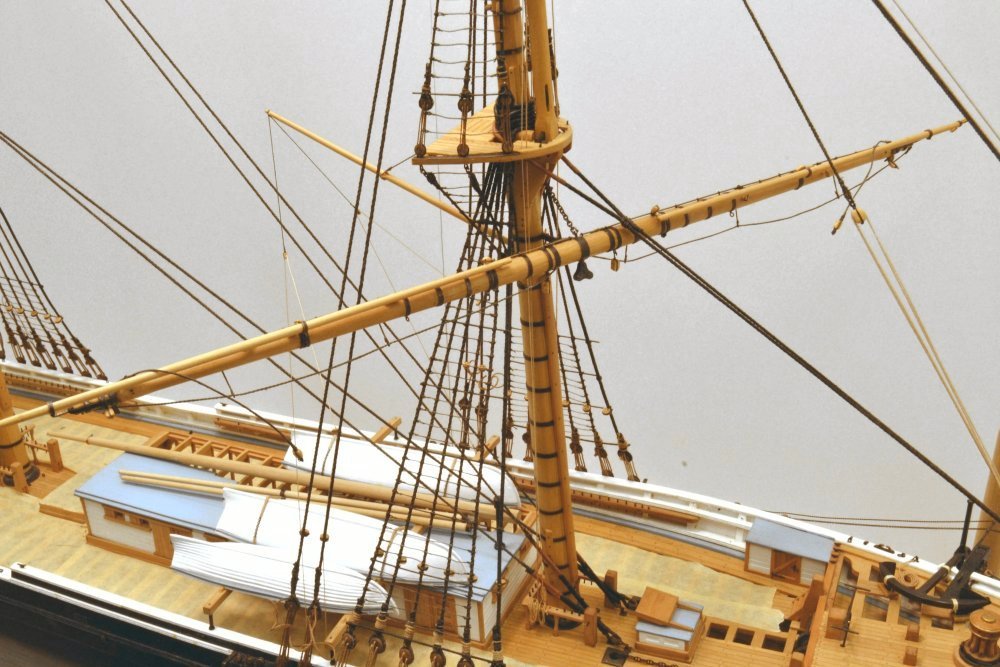
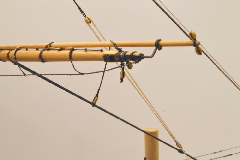
Young America - extreme clipper 1853 Part 255 – Fore Yard Topping Lifts Topping lifts supported the lower yards at the ends and allowed it to be "topped", that is lifted on one side, usually to clear dockside obstructions. Each lift consisted of a pendant secured to the upper eye on the fore yard arm band. This was connected to a luff tackle to the mast cap with the fall belayed on the foremast fife rail. A luff tackle uses a single and double block combination to produce a mechanical advantage of 4. The double block is secured to the foremast cap band. The first picture shows the port side lift strung up. Temporary thread lines to keep the yard roughly level for the rigging of the lifts lines may be seen in the picture. The next picture shows the single tackle block that is spliced on the end of the pendant with an eye. The standing end of the tackle has been seized to the eye on the block with smaller hemp line. The pendant is 6" line, the lift is 3". Excess seizing will, of course be removed. The outer end of the pendant shown in the next picture is spliced to a shackle on the upper eye of the yard arm band. Because the shackle is soldered, this eyebolt was installed in the band after soldering the shackle and splicing the pendant - before the yard was hung. The upper end of the starboard tackle is shown in the next picture. The double blocks were shackled to the cap band earlier, before it was installed. Both lifts have been strung up and given initial tension in the next picture. The falls are belayed on the fife rail shown in the next picture. Belaying points are being left unglued until all the running rigging on the yard is in place. The model yard is not heavy enough to put strain on the sling chain and force it fully down. This issue will be addressed in one of the next parts. The last picture shows the lifts installed and the yard levelled. Levelling was done by measuring up from the base board to the outer ends. Next, the reef tackles. Ed
- 3,618 replies
-
- 40
-
-
- young america
- clipper
- (and 1 more)
-
Sailor1234, I am not ignoring your balloon idea, just trying to internalize what that might look like. The theory is right - applying equal stress to each point along the line, but I can see a number of practical issues. Just touching these lines can upset things. Antscherl's idea in Swan IV of placing small wires along the line approximates the even distribution and seems very doable. Ed
- 3,618 replies
-
- 3
-
-
- young america
- clipper
- (and 1 more)
-
Thank you, Pat. I actually did something similar as shown in this picture: The stirrups were straightened by hanging weights (alligator clamps) from each stirrup using copper wire that is bent around the stirrup and over the foot ropa. You may be able to see this in the picture. This does a good job of straightening the stirrups, which were then wetted with diluted, darkened PVA glue. They stay straight if undisturbed, so I think this should be done very late in the modeling - at least of the yard, if not the whole model. I have not yet done anything with the foot ropes themselves. Ed
- 3,618 replies
-
- 12
-
-
- young america
- clipper
- (and 1 more)
-
Thank you all for the comments and likes - and for the suggestions about shaping lines. I am stiffening the foot rope stirrups with diluted dark wood glue, which seems to be stiffer than acrylic emulsion (eg. matte medium). This seems to work well if the stirrups are left relatively undisturbed, suggesting that this should be done late in the work when most handling is finished. I think less stiffening is appropriate on sagging lines, however the light weight of model rope does not produce catenary type curves naturally, so something may be needed if this effect is desired. As will be seen in the next few posts, I am starting with these running rigging lines taut - to relieve initial kinks - then will see what can be done to droop them realistically without over-stiffening - after the yards are firmly pulled down - more on that issue as well. Ed
- 3,618 replies
-
- 4
-
-
- young america
- clipper
- (and 1 more)
-
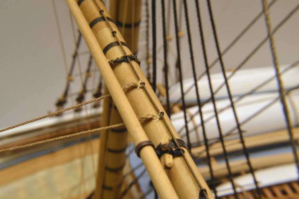
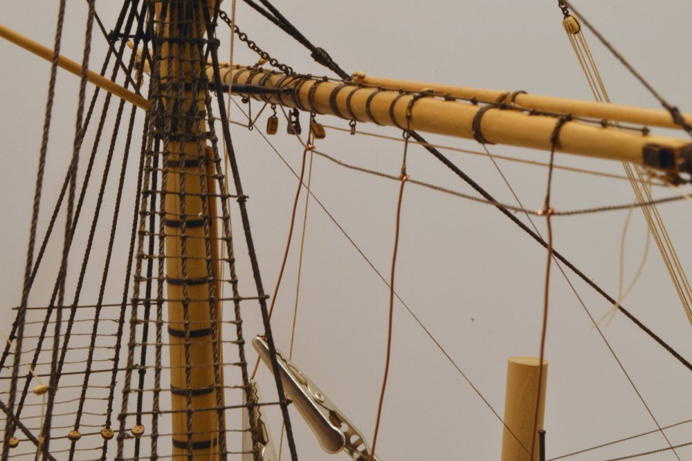
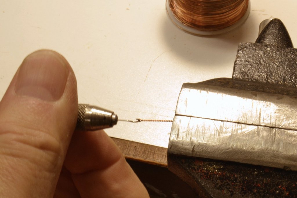
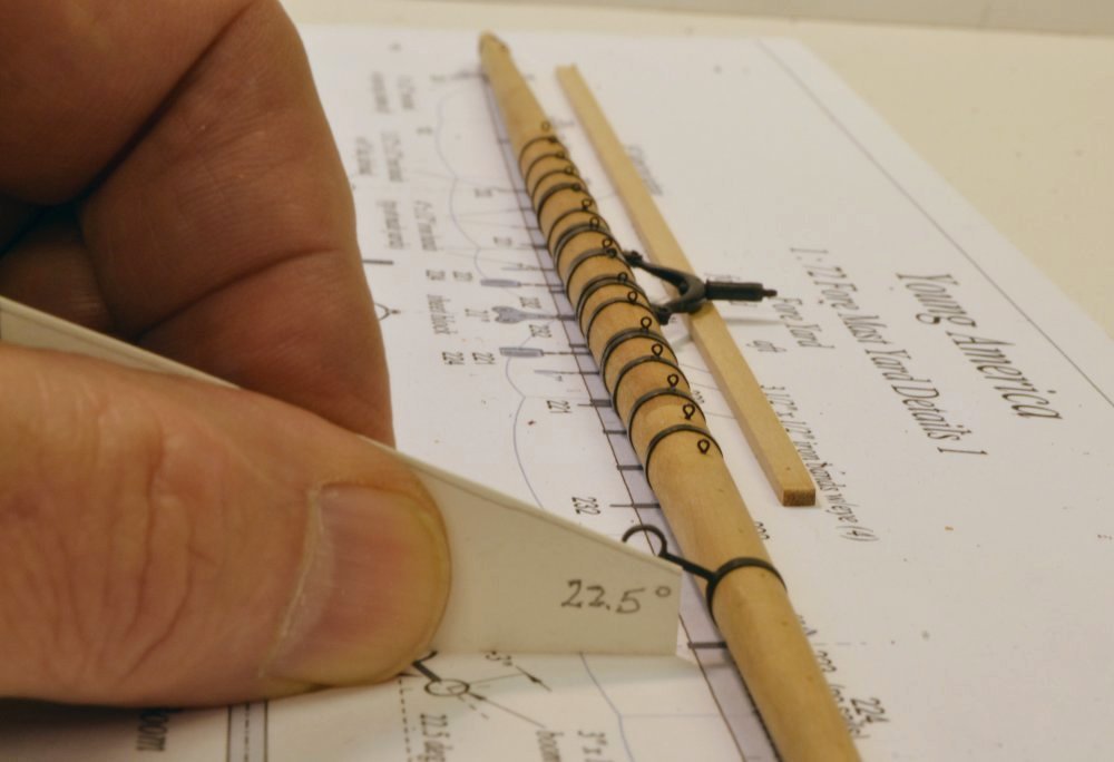
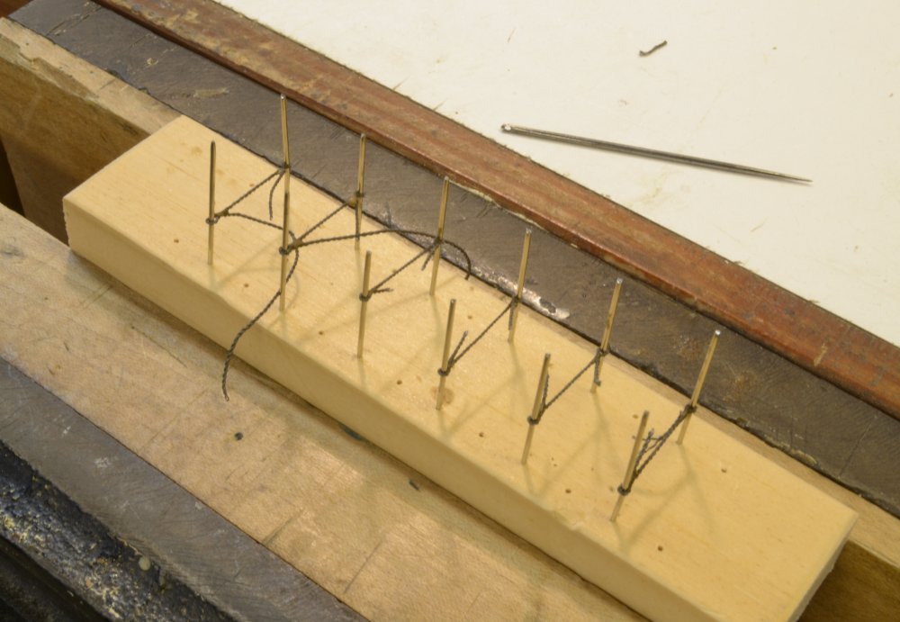
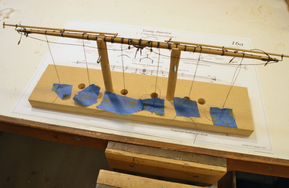
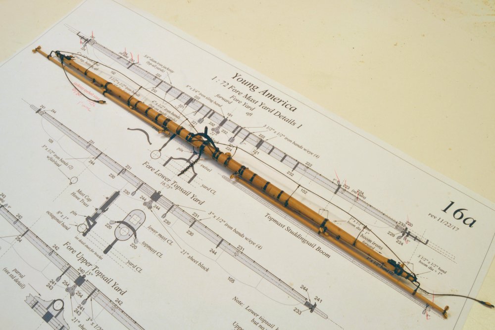
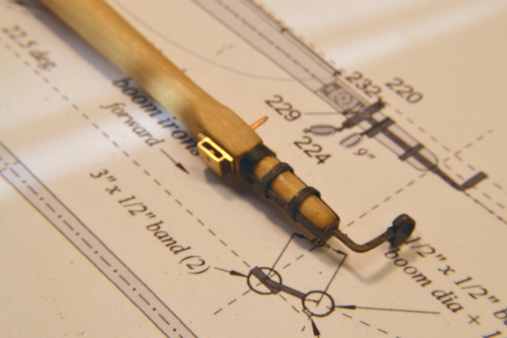
Young America - extreme clipper 1853 Part 254 – Fore Yard 4 Work has continued on the lower fore yard over the past couple weeks while various necessary parts were being "mass" produced. Some of these were described in the last few posts. Among the most numerous of these parts are the stanchions for the jackstays that run along the top of every yard The jackstays were 1" diameter iron rods, threaded through iron stanchions spaced about 30" apart. Given the number and the small size of these stanchions I made these as simple eyebolts that would just pass the jackstays that were made from straight, blackened brass wire. One of the eyebolts is being spun in the first picture. These are spun from 28 gauge copper wire. Holes along the top of the yard were described earlier. The holes were sized so these stanchions could be pushed in without the use of glue. Some of these are shown fitted to the central part of the yard in the next picture. The bands and metal fittings in the center of the yard were blackened and the yard finished with diluted Tung oil preceding the work at the ends. This was done to preserve the blackening of these parts through the continual handling of the yard during work on the outer ends. In the picture, one of the boom irons is being positioned using an angle template with the yard supported at the correct angle. These will be pinned with copper wire "bolts." I believe I mentioned earlier that these irons had to be modified to bring the boom closer to the yard – after this picture was taken, I believe. The next picture shows one of the yardarms during assembly. The yardarm band and the boom iron support bands are shown. The holes in the band for eyebolts have not yet been drilled. The cheek block is inserted temporarily before blackening. It will be secured by the large central pin and two small bolts through the side flanges. The next picture shows the yard hung temporarily with the jackstays and some of the blocks installed. The 4" footropes on the aft side of the yard were suspended from 3½" rope stirrups 3'6" long. These had eyes at each end – the upper eyes for lashing to jackstay stanchions and the lower eyes threaded through with the foot rope. In the next picture the six stirrups for this yard are being fabricated. The method for spliced eyes used on the ratlines is also used here. The pins in the fixture ensure equal lengths. The next picture shows the yard held in an assembly fixture for addition of various parts. This holder allowed all the required blocks, the lift pendants, the studding sail booms, and the footropes to be installed with minimal handling of the yard. The taped threads are used to straighten the footrope stirrups which were then treated with diluted dark glue. This process had to be repeated later after the yard was set and other work completed. The next picture shows the completed yard assembly, ready for setting. In the next picture the yard has been set. A permanent pin was fitted to the truss and the eyebolt on the chain sling was glued into the mast with CA. The last picture shows the starboard end of the yard. The foot rope stirrups are still misbehaving. The lift pendant is draped over the studding sail boom which is fitted with jewel blocks. The block shackled to the underside of the yardarm band is part of the reef tackle that will be installed later. The other suspended block is to support the lower studding sail yard that will not be installed. The blocks along the top of the yard are for bunt and leech lines. Ed

- 3,618 replies
-
- 43
-
-
- young america
- clipper
- (and 1 more)
-
HI Danny, I have not considered the XYZ readout seriously, but have looked at it. It looks like a nice accessory. The price is around 400 USD, probably 450 with PA tax and shipping. Certainly in the nice-to-have category. Ed
- 3,618 replies
-
- 3
-
-
- young america
- clipper
- (and 1 more)
-
Hi Steve, I bought my mill quite a few years ago. It was equipped with zero adjustable handwheels. The zero adjustment is very important because it allows you to set the wheel at zero before turning to a specified setting. This avoids having to calcualte the increments from the current position - something I unfortunately still have to do on my old Unimat. Here is a link to the adjustable wheels. http://sherline.com/product/34203430-2-adjustable-zero-handwheel-y-axiscrosslide/ Ed
- 3,618 replies
-
- 3
-
-
- young america
- clipper
- (and 1 more)
-
Thanks for the comments, guys - and also for the likes.. Maury the copper wire was filed flat to simulate iron strap after it was put on the shell. Frank, an end mill could of course be used, It is probably a trade off to make the different sized scrapers vs. setting up and aligning each different sized strip. Once made the scraper is very fast. I used to use scrapers to shape the sheave grooves, but that involves a lot of scrapers and the resulting blocks are not as good in my opinion. Ed
- 3,618 replies
-
- 4
-
-
- young america
- clipper
- (and 1 more)
-
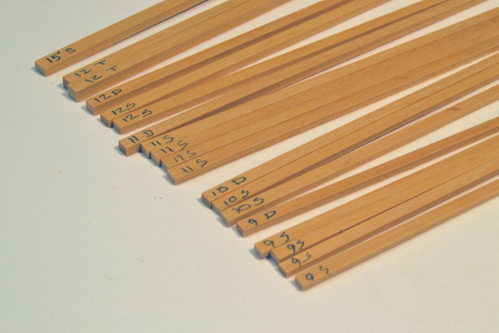
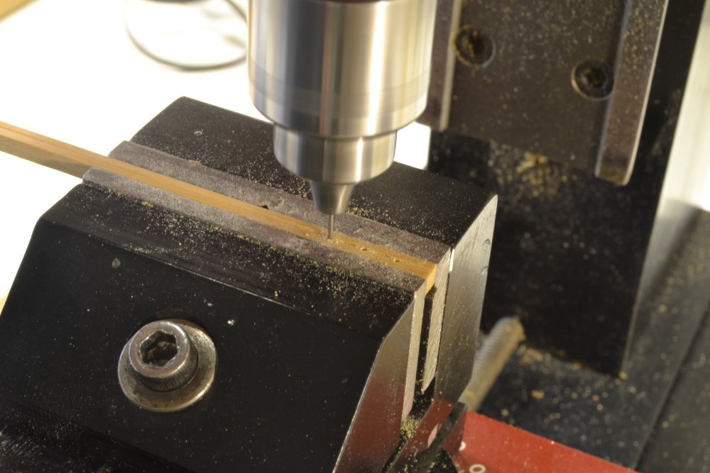
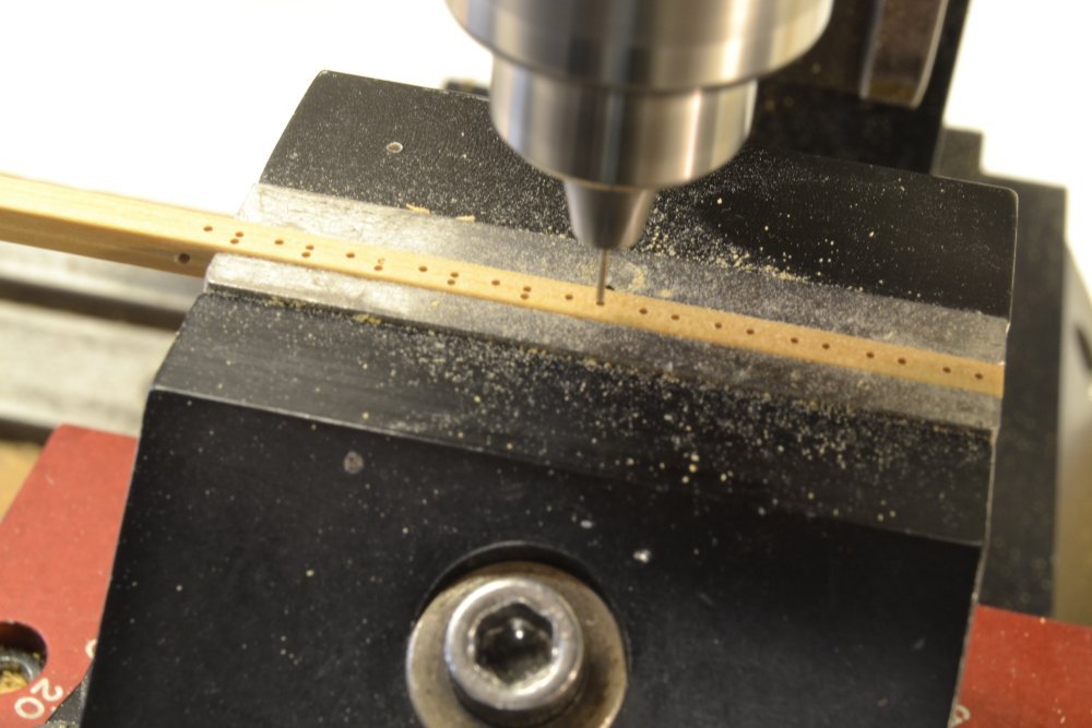
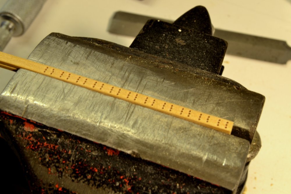
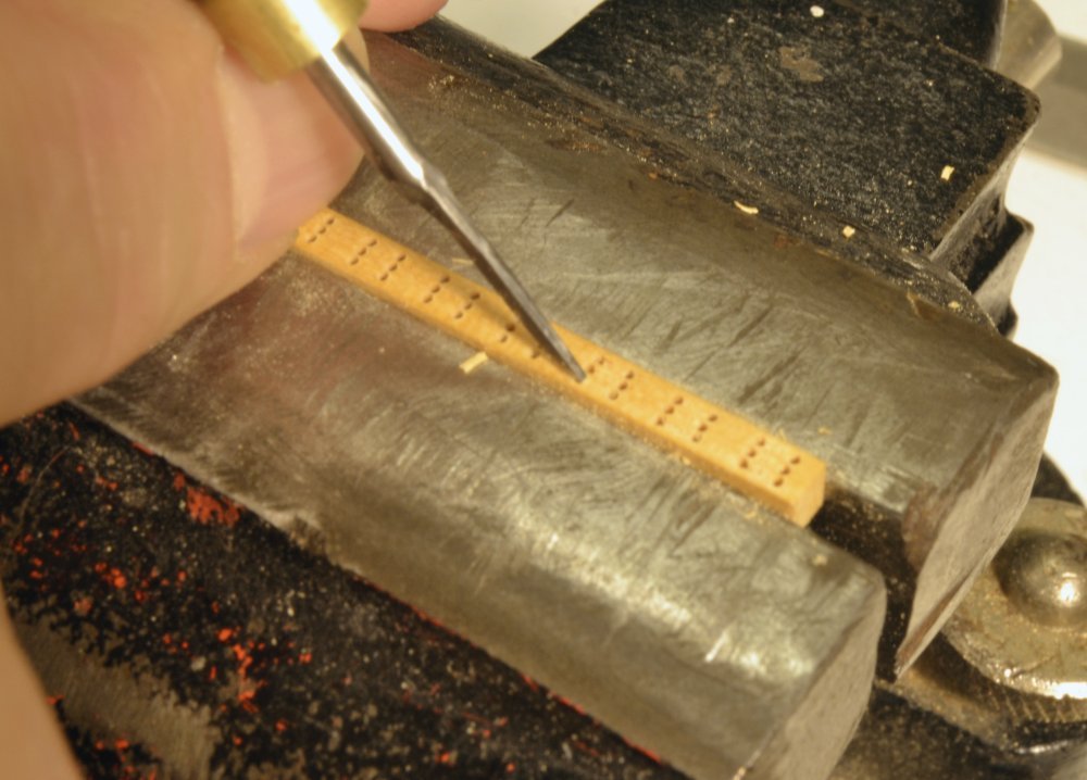
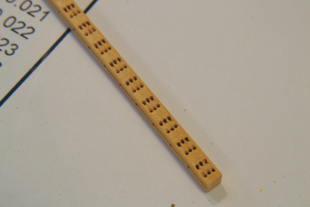
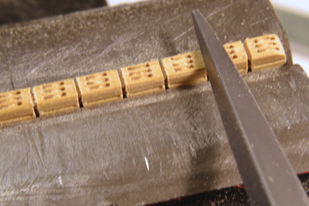
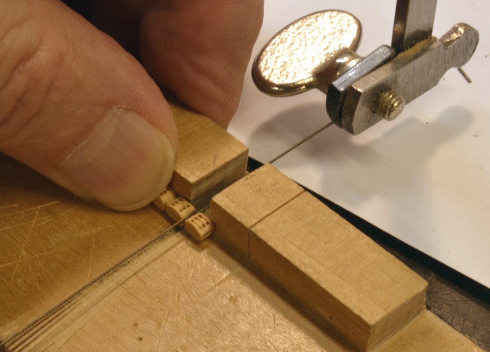
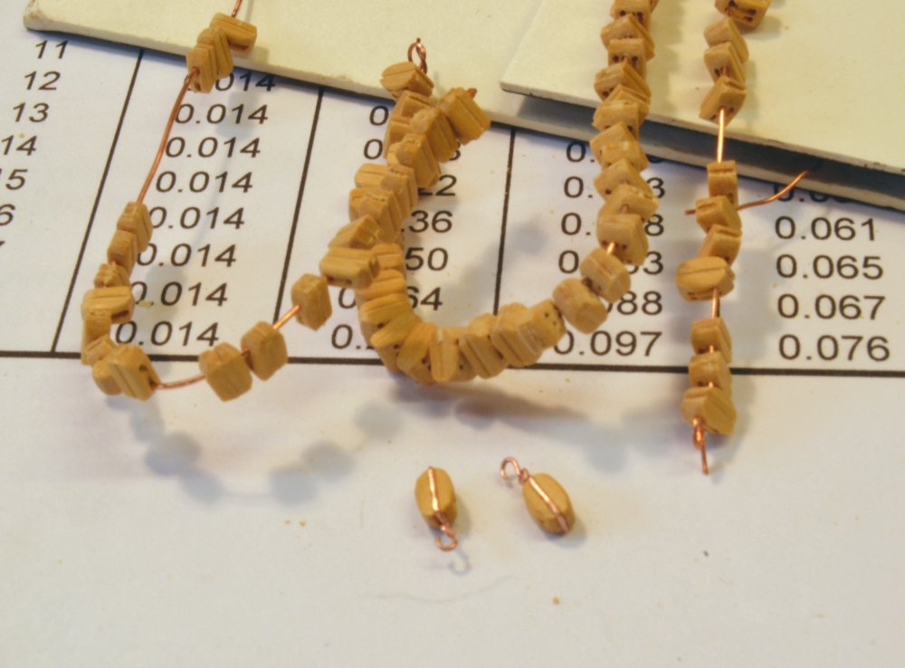
Young America - extreme clipper 1853 Part 253 – Wooden Blocks There are well over 500 blocks on the model, ranging from 15" in shell length down to 4". These include triple, double, and single blocks. Some will be iron strapped, some spliced to pendants, but most will be rope strapped. "Strap" seems to be the American usage for the word "strop" so I will adopt it for this American ship. Some of these blocks, in a range of sizes, will need to be fitted to the lower fore yard before it is installed. To avoid getting into one-at-a-time, piecemeal work, some mass production was adopted. So the next major task will be to make at least a substantial portion of the full requirement. The few blocks installed so far were leftovers from a previous model. At the outset of the rigging work a detailed "Rigging List" was developed to describe every line on the model, including its components. From this, a count of blocks of each type of block was tabulated. To that was added an estimate for studding sail blocks. Those lines are not included on the list. The blocks are being made from my best quality European boxwood – for hardness, strength, and color. Whenever I dip into what I have left of this wood, I immediately get frugal about waste. For the full supply of blocks, I sliced off a wood blank about 2" wide, 8" long, and slightly thicker than the shell breadth of the largest size, 15" blocks. The first picture shows strips sliced from this plank for all the larger blocks – down to 9" singles. Using the thickness sander, the 2" wide blank was first reduced in thickness to the shell breadth of the 15" blocks. A single strip was then sliced from this at the single block width. There are no 15" doubles or triples. For the next size down, the 12" blocks, the blank was again reduced in thickness. Adequate strips for triple, double and single widths were sliced off that – and so on. This one blank may suffice for all the blocks. The pictures below show work on the 12" triple blocks. I was surprised at the number of these – about 25 as I recall. Their use in triple-purchase tackles for topsail sheets account for most of these. To mass produce the blocks to specified dimensions, a table of block dimensions for each size was used to produce a drilling pattern and sequence. This was used to drill correctly spaced holes in each strip, starting with transverse holes at the ends of the shells to delineate length and also to provide a slight top and bottom groove to seat the strapping. This is shown in the next picture. Before drilling, a shallow groove was scraped along the strip on both outer shell sides. This is a modeling convenience that helps in seating the straps, especially the round copper wire "iron" straps that will be filed flat on the outside. Scrapers for this were made by machine grinding a razor blade for each shell breadth. The next picture shows the strip rotated in the vise for drilling of the smaller, 1½" (.022") sheave holes – six in each of these triple blocks. All holes were located using the calculated spacings, set by the mill's calibrated wheels. In the picture, the center row has been drilled and one of the outer rows is in progress. These holes are very close together, so sharp bits, short bit projection, high speed, and very light feed are essential. Even at that, the entry point of the drill in these unmarked holes may vary by a few thousandths as may be seen in the next photo. Next, slots were pared out between the sheave holes and the sheave curvature cut, using a small chisel as shown in the next picture. The chisel width was ground to match the drill size and then downsized for each smaller size of block. The next picture shows the strip after this slotting work. A knife edge file was then used to mark all four faces at the separation points using the first-drilled, transverse holes as guides. The blocks were then given a preliminary rounding with a barrette file while still attached as shown in the next picture. The next picture shows blocks being cut from the strip using a fine-bladed jewelers saw. Each block was then rounded to its final shape using a sanding strip. The last picture shows the finished set of 12" blocks, including two with iron strapping and hooks. The strapping on the two blocks shown will be blackened. The single blocks to the left have not yet been fully rounded. Ed
- 3,618 replies
-
- 40
-
-
- young america
- clipper
- (and 1 more)
-
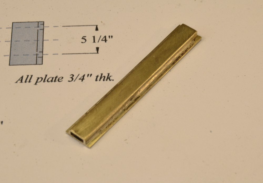
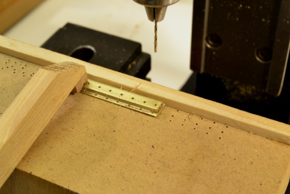
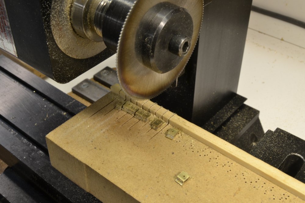
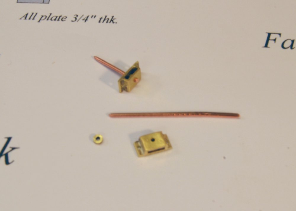
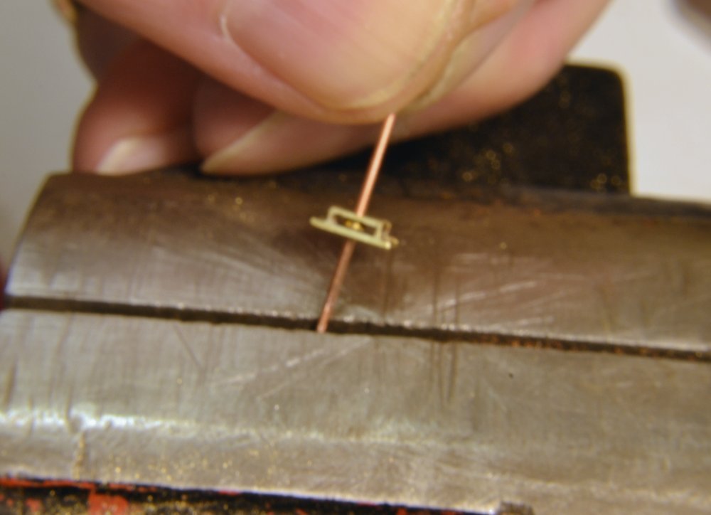
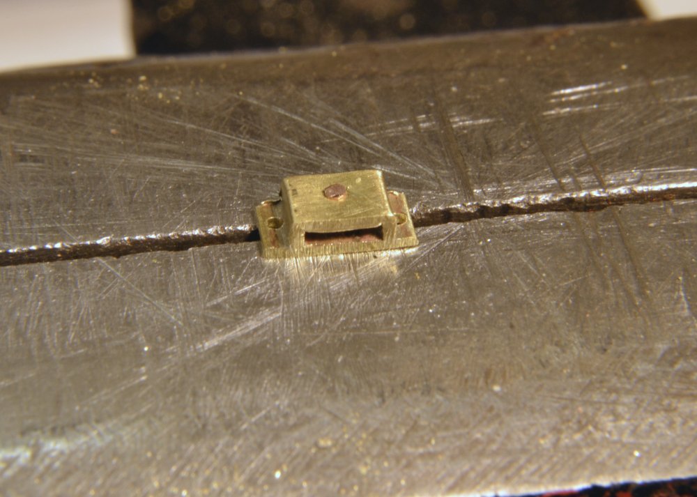
Young America - extreme clipper 1853 Part 252 – Cheek Blocks Iron cheek blocks will be bolted to the aft sides of the larger yards, on the square section just inboard of the yardarms. Small upper yards will have sheaves set in mortises at this location. These blocks direct the chain sheets inboard below the yard toward the sheet blocks described in the last post. The first picture shows one of the fabricated, larger, 16" blocks. The chain is threaded through as a test to ensure that it will pass. The casings and sheaves on these are brass. The large central pin/bolt is copper and will pass through the yard horizontally. Two smaller bolts will be added to the flanges later when the block is installed. The first fabrication step is shown below. A length of square brass tube was sliced to yield the U-shaped cap, shown silver-soldered to a flat plate. The blocks will eventually be sliced from this piece, after drilling all the necessary holes. This drilling is shown below. Again, the mill's calibration wheels were used to space the holes. The center holes were drilled first, then one row of the smaller flange holes, then the flange holes on the opposite side. The next picture shows the blocks being sliced off in the milling machine fitted with a thin slotting saw blade. The strip was clamped for this. The position of the fence and the downward blade rotation at the cut serve to keep the pieces from flying off. The next picture shows an assembled block and the separate parts. The sheave, conveniently, is the diameter of a brass tube, so sheaves merely had to be sliced off. This is being done with a razor saw in the next photo, using a jig with holes of different depths and diameters that was described earlier. The 2" deep hole was used for these. The sheaves were also filed clean and polished in the jig. In the next picture the sheave has been positioned and the axle pin/bolt inserted. With the long end gripped in the vise, the outer end of the bolt was clipped and peened to form a rivet head as described in the last post. Four of these 16" size are required – for the fore and main lower yards. Fourteen of the smaller, 14" size will be used on the crojack, and the six topsail yards. The smaller blocks will be made later. The last picture shows one of these test-mounted on the port arm of the fore lower yard. This picture also shows some rework that was done on the outer boom iron - the "Pacific" iron - and its inner partner (not shown). An earlier picture showed these positioning the boom quite far out from the yard. This has been corrected. Ed
- 3,618 replies
-
- 32
-
-
- young america
- clipper
- (and 1 more)
-
HMS Naiad 1797 by albert - FINISHED - 1/48
EdT replied to albert's topic in - Build logs for subjects built 1751 - 1800
Beautiful work, Alberto. Bravissimo! I cannot tell you what joy it gives me to see your beautiful work. Ed -
Wow. I am overwhelmed by the very generous comments on the last post - but a little disoriented in thinking about the possibility that Druxey would consider "fudging" something. That does not compute. As with many tasks on the model, this one had its fits and starts - mostly on the question of how to make all of them efficiently. Once over that hurdle and with some help from CAD, it was downhill. Deciding not to solder was a key decision and really simplified the work - and... thank you, Sherline. I don't know what we would do without those calibration wheels. There are no dumb questions Harvey, only dumb answers. I took the design of the sheet blocks from a detail on one of the drawings in Underhill, Masting and Rigging of the Clipper Ship and Ocean Carrier - a truly wonderful resource. I did not think too much about the four pins, but I believe that the central pin is important structurally, to maintain spacing, and to allow sheaves or the top pin to be removed without the whole assembly coming apart. There was probably a spacer boss on the center pin. Again, thank you all for following and for the flattering comments. Ed
- 3,618 replies
-
- 14
-
-
- young america
- clipper
- (and 1 more)
-
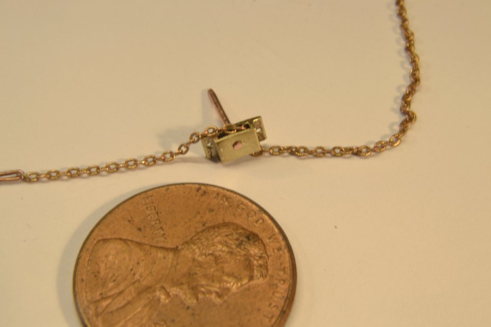
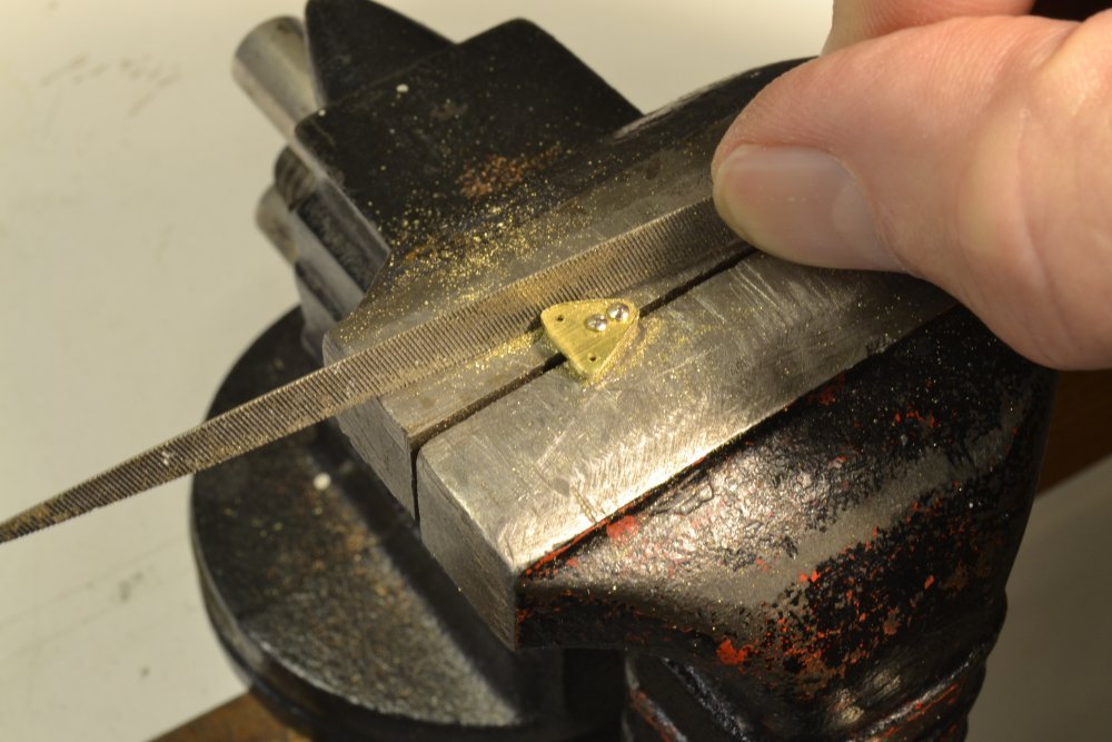
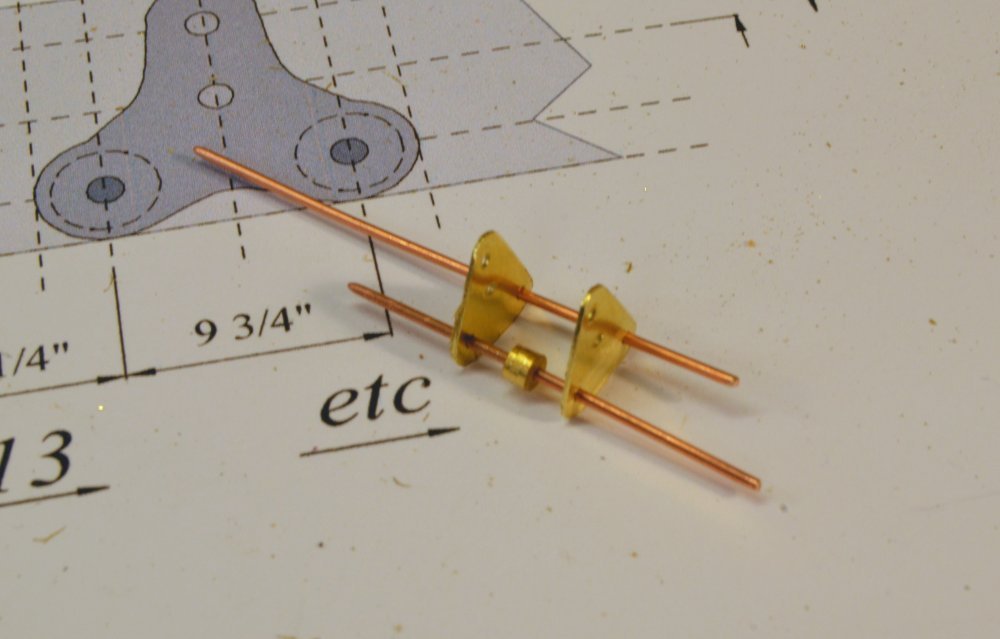
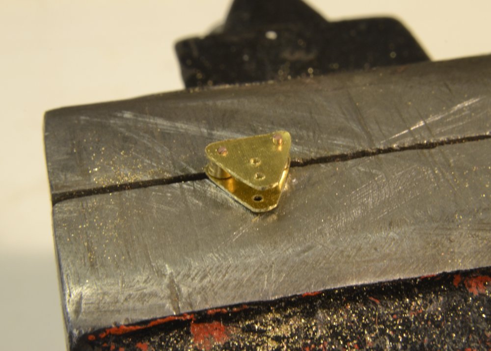
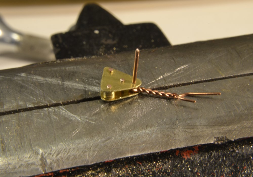
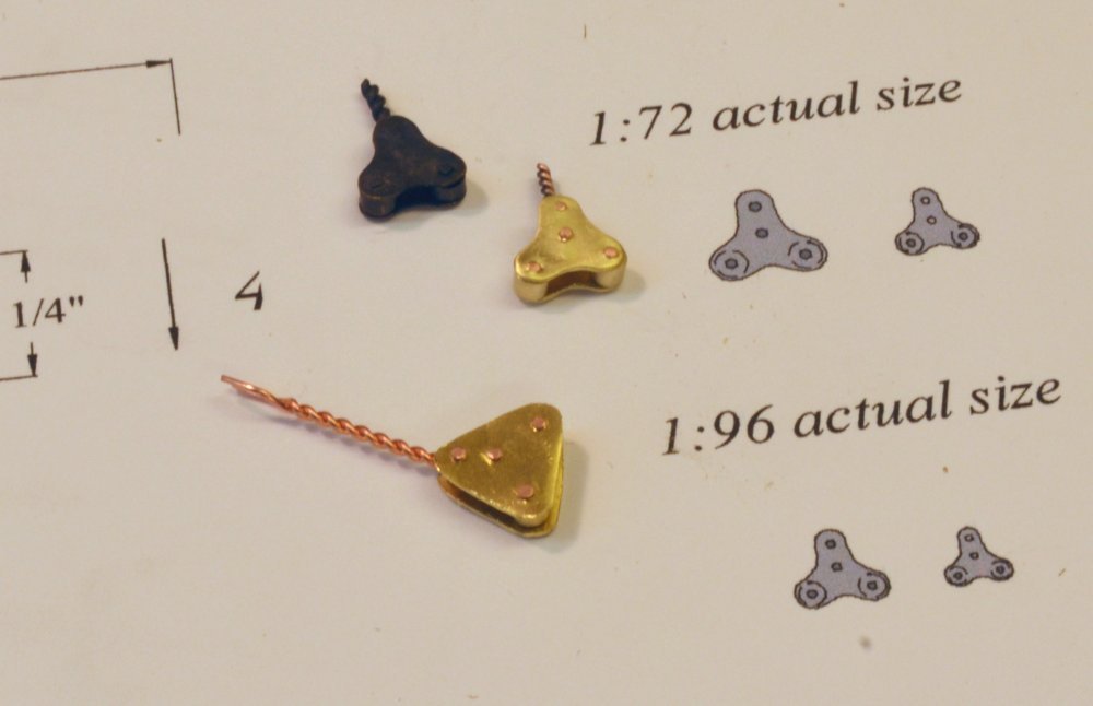
Young America - extreme clipper 1853 Part 251 – Sheet Blocks Each square yard, except for the skysail yards at the tops of the masts, will be fitted with an iron sheet block suspended from an eyebolt below its center. These "cloverleaf" type blocks contain two sheaves, one for each of the two chain sheets for the sail directly above. The sheets pass through sheaves in the yardarms, or cheek blocks on the larger yards, through fairleads under the yard, then to the sheet blocks. The blocks direct the sheets downward to tackles that are belayed on deck in most cases. The first picture shows the seven fabricated, 21" sheet blocks with eyebolts attached. Two of these have been blackened. This size will be used on lower, lower topsail, and upper topsail yards on the fore and main masts and on the crojack yard on the mizzen. The remaining yards will be fitted with smaller, 15" blocks of this type. To make these efficiently, some "mass production" was used. In the first step, holes for all the plate casings were drilled as shown in the next picture, through two long strips of .010" brass, ¾" at 1:72 scale. The holes were drilled using the mill as a drill press, with holes spaced using the calibration wheels, in a prescribed sequence using calculated spacings. The resulting strips, for both block sizes are shown in the next picture. Part of the drilling guide sheet may be seen in the picture. It shows each movement in a numbered sequence, with penciled spacings calculated from the full size dimensions. The punch marks on the strips were added for matching. In the next picture two dressmaker pins have been inserted through the holes on the vertical centerline of two matching plates. The rough shape of the block was cut through both plates using scissors. The two pins are close fitting, and in the picture below are clamped in a vise where the triangle shapes are being sized with a file. There is a thin, drilled wood shim under the two plates for clearance above the vise. In the next picture the triangular shape has been filed, the plates separated, and the pins have been replaced with lengths of drawn copper wire. One of these wires has been threaded through a turned sheave. In the next picture, with both sheaves fitted, the lower ends of the pin wires are clamped in the vise. In this picture the upper wire ends have been clipped off just above the top plate and then peened to form rivet heads. The assembly was then turned over and placed on an anvil. The long bolt ends were then clipped and peened. In the next picture the central pin has been peened on both sides in the same way and the top pin has been inserted through a spun eyebolt. As before, the lower ends of the pin wires are clamped in the vise for peening the first side. The block was then flipped over to clip and peen the other ends, completing the assembly. The lower block in the picture below shows this stage. Each side of the triangle was then filed concave, shaped to match the pattern and polished. The fourteen smaller sheet blocks will be made later. Ed
- 3,618 replies
-
- 45
-
-
- young america
- clipper
- (and 1 more)
-
Thank you, Roger, Peter and all for the likes. Roger, I have not found much about Webb's yard - except about the large bell at the gate - so I can't really comment, except to say that Webb was one of the largest, if not the largest yard in America at mid-century and as a thriving shipbuilding city, New York had an impressive array of contractors supporting the industry, so I am inclined to believe that the latest equipment would have been in use. I have read that McKay's yard in Boston at the time was equipped with a steam-driven saw that could bevel frames - pretty sophisticated. I doubt that Webb would have been outdone in equipment capability - but I don't really know. Nice words, Peter. Always good to hear. Ed
- 3,618 replies
-
- 2
-
-
- young america
- clipper
- (and 1 more)