EdT
-
Posts
2,214 -
Joined
-
Last visited
Content Type
Profiles
Forums
Gallery
Events
Everything posted by EdT
-
Thanks for the help with my careless spelling, Greg. Clew vs. Clue is right up there on my list with Sheer vs. sheer, bitts vs bits, etc. Ed
- 3,618 replies
-
- 1
-

-
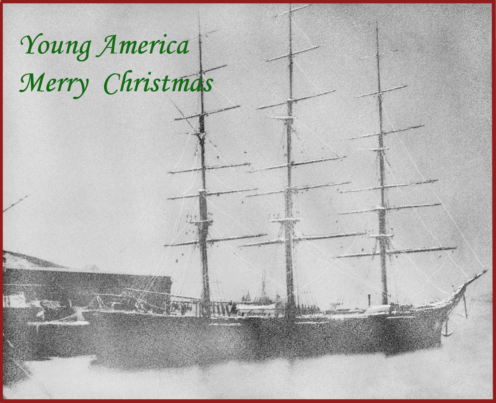
- young america
- clipper
- (and 1 more)
-
Thanks, everyone, for the comments and likes - most appreciated. Not a lot to show these days - mostly splicing, tying and lashing ratlines. Tedious work. Ed
- 3,618 replies
-
- 3
-
-
- young america
- clipper
- (and 1 more)
-
HMS Naiad 1797 by albert - FINISHED - 1/48
EdT replied to albert's topic in - Build logs for subjects built 1751 - 1800
Bravo, Alberto! Love the figurehead. Ed -
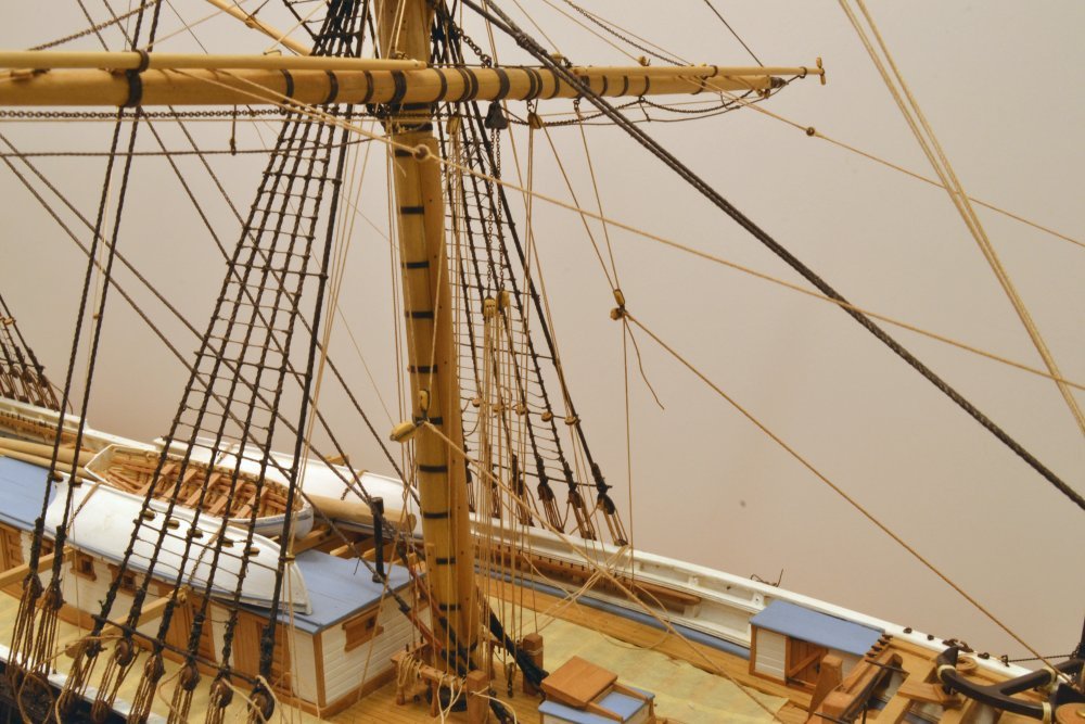
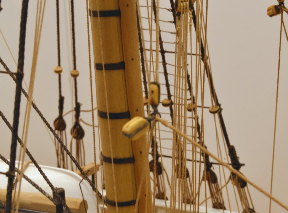
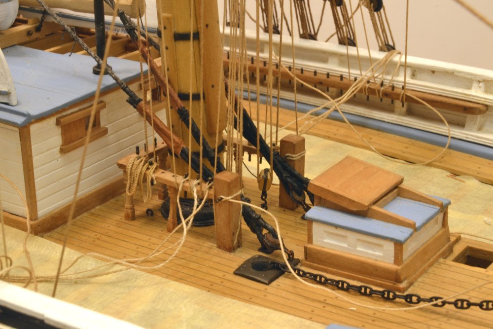
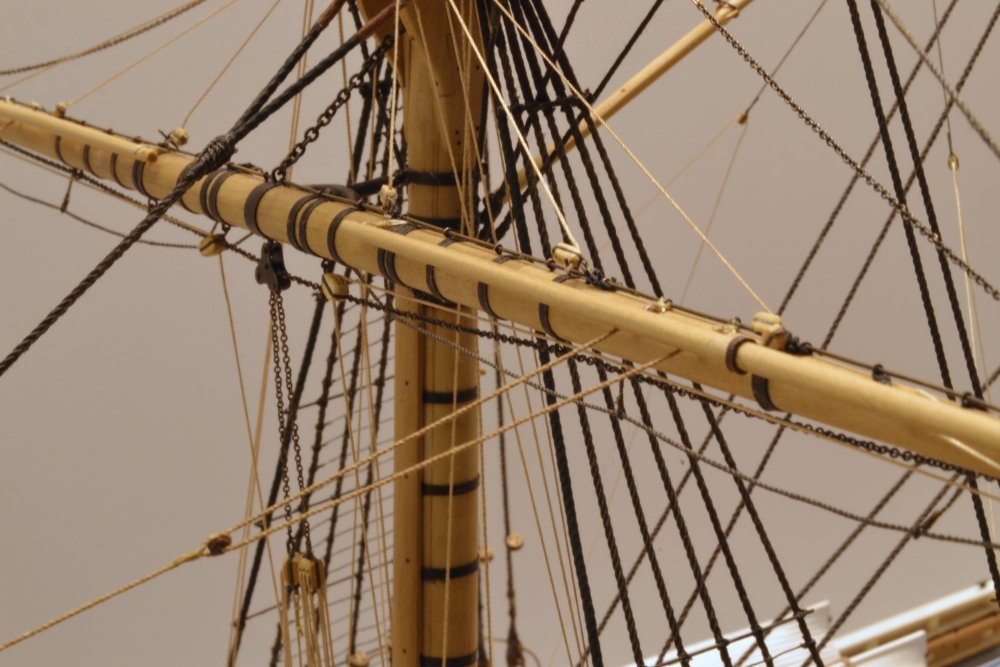
Young America - extreme clipper 1853 Part 260 – Clew Garnets, Tacks, Lazy Tacks Clew garnets were used to pull the lower corners of the sail up to the bunt when furling. Blocks for these lines were shackled together with the sheet blocks, tacks and lazy sheet/tacks. These shackles were attached to iron clue rings or cringles on the sail. For these lower sails, this was done on deck before the sail package was hauled aloft. On the no-sails model the sheets, tacks and lazy tacks are suspended from the clew garnets. The sheets will be added later. Sheets were used to restrain the clews of the sail, the tacks to haul it forward when braced, and the lazy tacks to help control the sail when shifting from sheets to tacks. On the model these lines are tensioned in a way that will position the shackled blocks and eventually allow the sheets to drape gracefully. The first picture shows these lines rigged. The clew garnets are shackled to an eye under the yard. The line then passes through block on the shackle, back through the forward sheave of the double quarter block hooked under the yard, then down to the fife rail. The lines that go directly down from the shackle to the pin rail are the 4" lazy tacks. These would be belayed at any convenient location. The line slanting forward to its cleat on the cathead is the 5" tack. Both these lines had their eyes at the shackle formed in place. The tail of one has not yet been clipped off in this picture. The next picture shows a close-up of the shackle on the starboard side. The larger, empty sheet block is to the left of the shackle. The next picture shows the fife rail with the clew garnet belayed on the first pin. I finally decided to re-order the pins, moving the topping lift falls back to the third pin and the reef tackle fall to the second. This avoids crossing lines. The topsail sheet falls have also now been run through the outer sheaves on the sheet bitts and are temporarily belayed. I may move these to the inner sheave. The next picture shows the run of the tacks to the cathead cleats. And finally, the belaying of the lazy tack on the first pin of the main pin rail. The lines on pin 3, 4, and 5 are the two buntlines and the leechline. Ed
- 3,618 replies
-
- 40
-
-
- young america
- clipper
- (and 1 more)
-
The flags look great, Micheal. I have not used Silkspan - except perhaps unknowingly in the long past on a model airplane. It should be much more durable than tissue. I have used finely woven drafting linen from the days before polyester films. The wax has to be removed first. One thought on your printing: Hopefully your printer uses non-fading pigmented inks suitable for archival photos and not the short lived dyes used in some printers. Worth a check. If you're not sure, I'd use Druxey's advice of acrylic paints. Ed
- 749 replies
-
- 8
-
-
- albertic
- ocean liner
- (and 2 more)
-
Thanks, everyone. Landlocked, my only previous experience with this was my Victory model, which was also heavily rigged but had only 9 square yards, whereas this model has 18. So I am anticipating issues down the road and expecting some frustration as things start to get congested. I am loosely following some general sequence rules: forward to aft, lower to upper, and standing before running on each mast or spar. I also expect to complete one yard at a time, holding off on permanent belaying until rigging on each yard, or other collection of lines can be safely tensioned and fixed. Although I used several belaying diagrams for guidance in preparing the drawings, I fully expect to make changes to uncross lines or to avoid interferences. I have already made some of these adjustments and will incorporate them on the final drawings and other information. Your are right, though, there is a head-exploding number of lines on the model - well over 700. Ed
- 3,618 replies
-
- 6
-
-
- young america
- clipper
- (and 1 more)
-
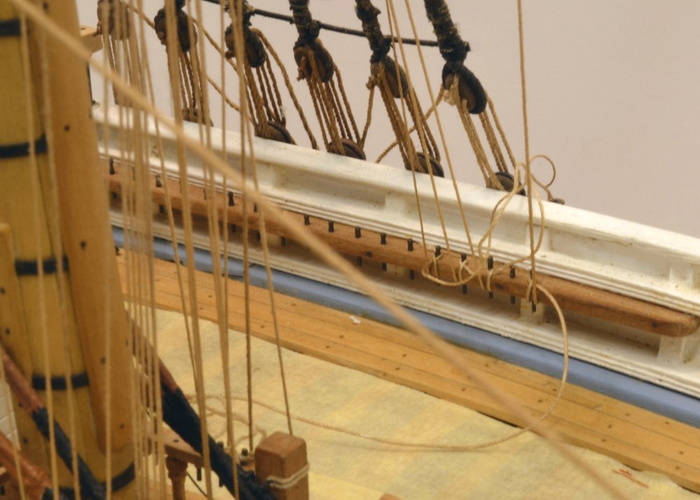
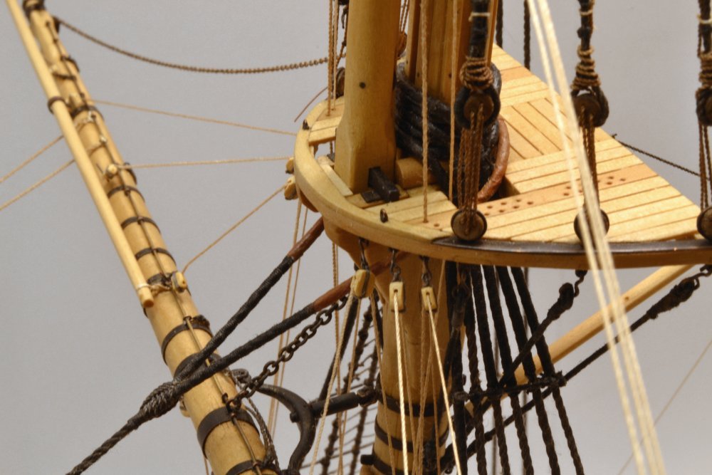
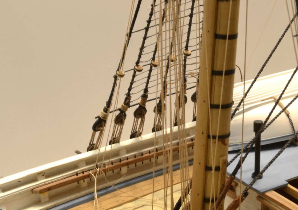
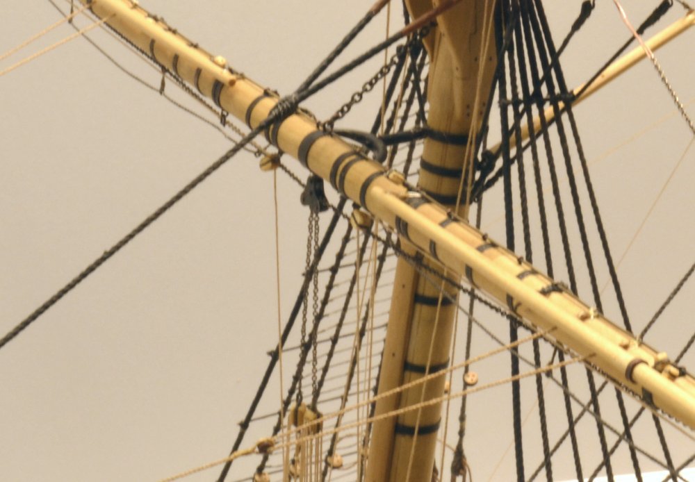
Young America - extreme clipper 1853 Part 259 – Lower Course Buntlines and Leech Lines Buntlines and leech lines were used to bring in the lower and outer edges of square sails when furling. In the case of the lower sails, the courses, they were also used to make up and raise the sail package to the yard for bending. Buntlines were toggled or knotted to cringles on the lower edge of the sail, leech lines to cringles on the sides. On lower sails these lines then passed through lead blocks on the yard, single blocks hooked under the rim of the top, and down through shroud fairleads to belay on the main pin rails port and starboard. The first picture shows these lines on the fore yard. The four inner lines are the buntlines and outside are the single and smaller leech lines. The lines pass through lead blocks lashed to the jackstays. On the "no sails" model, the lines are stopped at the block with toggles that would be used to fasten to the sail cringles. These toggles may be seen in the next two pictures. The toggles, were made from small lengths of wire, passed through the line and glued to simulate an eye. The next picture shows the blocks at the top. The blocks on the 3" buntlines are 9", on the 2½" leechlines 8". And finally, the lines passing through the shroud fairleads to the pin rail. As with all the running rigging for this first yard, final belaying and tensioning will not be done until all lines for the yard are rigged. This will facilitate getting the right level of tension and avoid rework. For this reason lines may not appear properly tensioned and a mass of excess lines clutter the deck at this stage. Ed
- 3,618 replies
-
- 37
-
-
- young america
- clipper
- (and 1 more)
-
No, I have always planned double topsails that were installed the year after launch, hence the Howell type brackets on the three lower mastheads. Ed
- 3,618 replies
-
- 3
-
-
- young america
- clipper
- (and 1 more)
-
Checked out the thread site, Micheal. DNC Cordonnet is one of the brands I am using on Young America - using some as isfor small lines, some made into rope. Also using Fincrochet - a similar thread. Ed
- 749 replies
-
- 4
-
-
- albertic
- ocean liner
- (and 2 more)
-
Hi Rob, I intend to fully rig all the yards and booms. As I may have mentioned previously, though, the stuns'l rigging will not be included except for what I think would be permanent blocks. Ed
- 3,618 replies
-
- 2
-
-
- young america
- clipper
- (and 1 more)
-
Thanks for these additional comments, Sailor. I don't really have anything to add to my previous comments on the sheet tackle falls. On reeving vs. lacing of triple blocks, I am familiar with the practice you describe from descriptions in modern sources, but have seen no references to reeving the fall from the central sheave on triple blocks in text or diagrams in contemporary sources of the time. So you may assume all triple blocks on the model will be laced from one side to the other. Ed
- 3,618 replies
-
- 2
-
-
- young america
- clipper
- (and 1 more)
-
Hi Scott, Thanks for the question. I welcome these and I know there will be many to come on these rigging details. For belaying detail I used mainly Underhill and number of Crothers Sea Gull clipper plans, plus notes in other references. As is often the case, some interpretation is needed and I rationalize that at least partly on the fact that individual captains did many things to rigs based on their own preferences - up to and including yard sizes and mast heights. While almost none of these variations is documented, I believe the practice leaves latitude in how to handle some rigging details - within limits. The advantage of the sheet fall coming out of the lower tackle block as you describe is that it could be manned by more men, presuming, of course, that a clear path could be found from within the fife rails surrounding the lower blocks. As you will see later, this area is highly congested, so congested in fact that the sheet tackles for the upper topsail will belay on the fore top using similar tackles. There is not much room in the top for a horizontal lead and the sails are about the same size, so it is not unreasonable to assume that similar configurations could be used. Also, crew sizes were small, hence the triple purchase tackle, which has a mechanical advantage of 6. So, I think the lead from the tackle could be rigged either from the top or the bottom block. If conditions demanded, a runner block could also be rigged at the deck, or more likely, a sheave in the sheet bitts could be used. I may yet run the lead through one of these. Based on this logic I ran the lead down from the top block allowing easier access to it. I would argue that either method could have been used - and perhaps others. Twisting of lines: First, it is important to eliminate residual twist stress in the ropes after thye are spun. Depending on the ropemaking process, this may be done by not over-twisting the rope as it is made, then allowing any twist to be relaxed after spinning, followed by a good stretching. I notice that even with those precautions lines will revolve when hung with a weight after dyeing. I usually constrain this, but I may let one go to completion to see if I am still left with rope. Tackles will still likely twist up. That is one reason why I threaded them as shown above. The ones shown still wanted to twist up. I took note of the hook orientation after threading them and made sure that I maintained that when hooking to the eyebolt. Fortunately, chain does not want to twist, so the tackled stayed as placed. Having the fall come out of the top block helps, by the way, but that was not part of the logic. A rope pendant will tend to twist more, so that stress has to be gotten out beforehand, especially with long pendants. I did not experience the problem on the topping lifts. Ed
- 3,618 replies
-
- 7
-
-
- young america
- clipper
- (and 1 more)
-
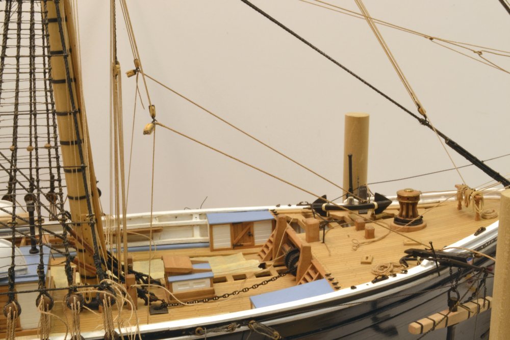
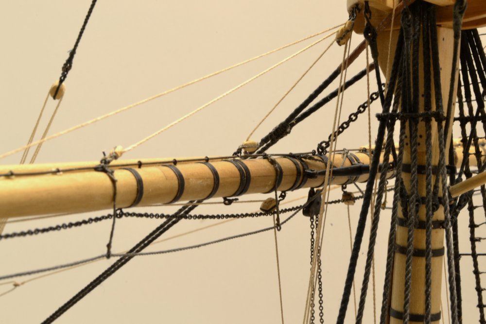
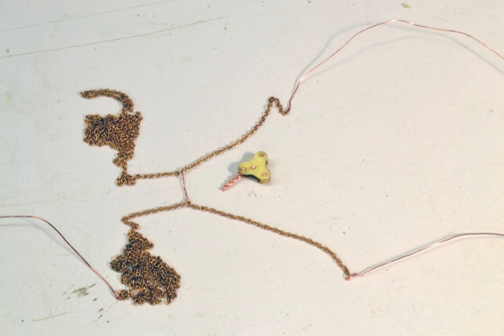
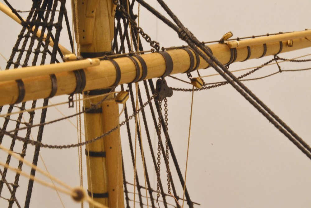
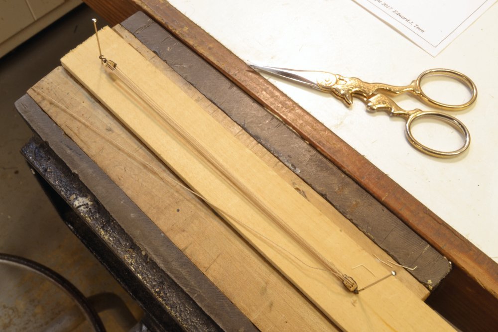
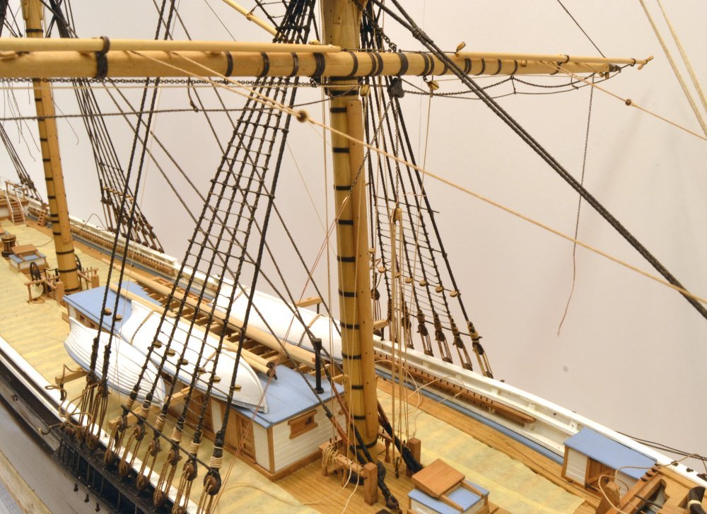
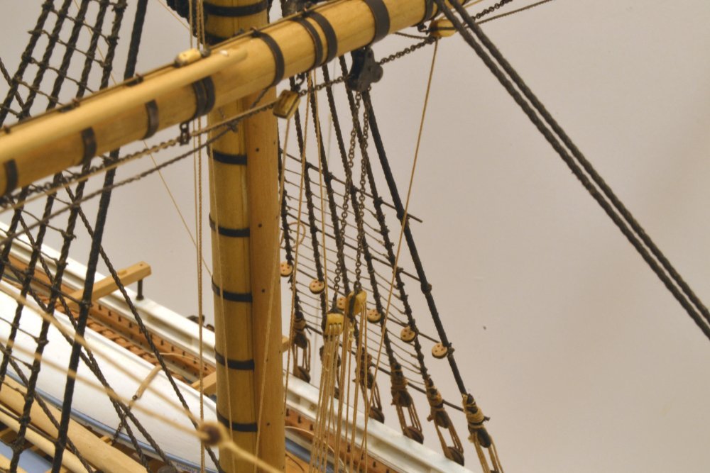
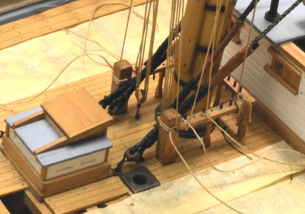
Young America - extreme clipper 1853 Part 258 – Fore Lower Topsail Sheets 1 Sheets restrain the clues (lower corners) of sails. They are attached to common shackles with the topsail clue lines. These shackles are hauled down to the cheek blocks in the lower yard by triple tackles at the deck. When sails are furled or unbent, the clues and the attached sheets are hauled up to the bunt, the center part of the topsail yard. Chain was used on sheets (and halyards) for durability in resisting constant working through the sheaves due to wind fluctuations on the sails (and yards). It may seem like an odd time to be installing these, but I intend to use the sheet chains to haul all the yards down to put tension on their sling chains or, in the case of upper yards, their halyards and standing lifts. The model yards are too light to fall of their own weight. To do this, the sheet chains will be stopped together inside the sheet blocks so that putting tension on the sheet tackles will hold the yard down and also allow the chains under the yard to sag realistically. The method uses a wire connection between the two sheets as illustrated below. The wire strap between the two separate sheet chains will loop over the central pin in the block. The short legs will drop inside their respective sheaves. The stopper link will be invisible as seen in the next picture. The drooping horizontal chains in the picture are reeved through the fairleads under the yard, through the cheek blocks then temporarily suspended above until their yard is rigged later. These upper legs are unaffected by tension on the lower ends. The lower ends of the chains are secured to triple-purchase tackles that hook into eyebolts in the deck. These were strung up as shown below before installing. In the next picture the port tackle has been rigged. The upper block is "shackled" to the chain – in this case fastened by a shackle-like, knotted loop of wire. The opposite chain is tied off temporarily with wire awaiting its tackle. The next picture shows both tackles secured to their chains. The lengths of chain on each sheet is long enough to haul the lower topsail clues down to the lower yardarms from their initial position when the topsail is bent to the yard, so these triple purchases use up a lot of rope – most of which ends up coiled when the sail is rigged. The next picture shows the lower ends of the tackles hooked to the eyebolts and belayed on the long pins through the sheet bitts. These connections will probably be re-configured later, but for now the tackles have pulled the yard down and tightened the sling chain as may be seen in the last picture. Ed
- 3,618 replies
-
- 37
-
-
- young america
- clipper
- (and 1 more)
-
Not to worry, Sailor123.... You have not been keeping me up and I like questions, especially the hard ones .....usually. Ed
- 3,618 replies
-
- 1
-
-
- young america
- clipper
- (and 1 more)
-
Thank you, Gary. its good to have you back with us. The timing of Young America Volume III will be just as soon as we can get it, but of course, I will have to finish the model in order to finish the book. I am working on both - and of course the biggest job, the drawings. Progress on the model will be the key indicator. Thanks for your interest. Maybe we can drag you away from those British men-or-war to a sleek, fast 19th century American beauty. Cheers, Ed
- 3,618 replies
-
- 1
-
-
- young america
- clipper
- (and 1 more)
-
Thank you, Rob. As far as the colors are concerned, I generally adopted the scheme proposed by Crothers or evident from the photos - with the exception of the masts and spars which I am leaving natural as you see in the pictures. Ed
- 3,618 replies
-
- 1
-
-
- young america
- clipper
- (and 1 more)
-
I concur with all the comments about Underhill's book. It has been invaluable to me in my efforts to devise a credible rigging plan for Young America and I recommend it highly. It was a necessary resource, but on its own not sufficient, and a long list of other references were needed, mostly 19C documents but some from secondary modern authors, like Crothers, Lees, Campbell, Harland. etc. - also, photographs, especially those of YA, but many others. I will not document the full list of sources here. The list grows by the day and may look different by the time I finish the work. The subject of interference between the sail head and boom irons raised by Sailor 123... has occupied all my available modeling hours over the past two days. I am sorry to say I have found no explanation of how this was handled on ships in the 1850's time frame, and not even a mention of the problem. Additional "bending" jackstays were sometimes fitted more forward on the huge steel yards of later years but there is no evidence of these on Young America. This remains a mystery. Even the most detailed descriptions of bending sails make no mention of this issue. If a documented solution were found, I would be inclined to remove and rebuild the lower fore yard to suit, so if anyone has an answer, I am open to it. However, undocumented opinions will not be enough for that. In the absence of any mention of this problem in any of the sources, I can only assume that the sails were stretched around the irons, a detour of about one foot in forty. Thanks for the input on this issue. Ed
- 3,618 replies
-
- 4
-
-
- young america
- clipper
- (and 1 more)
-
Micheal, a few thoughts on your rope making. I suspect that you are making right-handed rope using what is probably right-handed thread. You may know this, but if so, the thread needs to unravel first before starting to twist into the left-handed strands that will begin to wind into right-handed rope. Hence the delay in the top starting to move - not a problem. I assume the polyester thread you are using is right-handed. Cotton thread is usually if not always, right-handed, linen left-handed. You might consider using straight crocheting cotton for the small lines. I am using different sizes of this as-is for a number of smaller line sizes and also for making larger rope. Since it is already right-handed it looks good. You could also use two strands in your small rope - not an unusual ship-modeling method. My experience with cotton-polyester line on an earlier model is that it stretches more the long-staple cotton, but since it is plastic it is not much effected by humidity. Mercerized cotton-polyester is more fuzzy than than linen or the long-staple cotton that I am using for rope (Fincrochet and DMC). For lashings I am also using a lot of Guterman 100 cotton which has a very fuzz-free finish. It also makes nice spun rope. To remove fuzz, I pass the finished rope, after dyeing, through the flame of an alcohol lamp (quicky of course). Got this idea from Longridge. It works. I am using natural walnut extract stain made from VanDyke crystals dissolved in water to get the hemp color, diluted India Ink for black tarred rope. Natural vegetable dyes are non-fading - example antique oriental carpets. India ink is pigmented with some shellac and is also non-fading. Druxey's suggestion of watercolor, being pigmented, would also be non-fading, as would dilute acrylic paints. I love the pictures of your vertical machine. I was aware of them, but had never seen one. It should solve a lot of the friction problems in horizontal setups like the one I - and probably many others - use. I guess length could be an issue. I normally make 6 to 7 foot rope on an eight-foot walk, cut down from the 12' walk I used to use.. Good luck. Its one of my favorite love-hate pastimes. Ed
- 749 replies
-
- 5
-
-
- albertic
- ocean liner
- (and 2 more)
-
I believe your description of raising sails applies to the upper sails but not the courses - at least according to the sources I am using. Primary sources: Nares, Seamanship 1868 London and S.B. Luce Seamanship 1863, 1868. Luce is American. Secondary: Harland, Seamanship in the Age of Sail, 1984. The same description, with diagram, may be found in Lever, Young Officers sheet Anchor, 1819. So you may want to check your sources. Perhaps the method you describe was used on courses in later times. Upper sails could not be raised in this way because of the stays, or as you say, to avoid overlong bunt, leech and clue lines. The courses were below the stays. Also, sails above the topgallants were normally bent to the yard before raising. By the way, I neglected to list the clue garnets in my first description of raising the sail. I cannot answer your question on the interference of the boom irons with the head of the sail, except to say that the details of the boom irons and their orientation I used are well documented in multiple sources. This configuration is also visible in the photo of the ship. It is unlikely that the sails would be notched around them since this would involve cutting the headrope. This would weaken the sail. There would also be problems in stretching the sail on the yard. I can only assume that the head rope ran under the irons at these points, forcing the head of the sail out about 8" from the jackstays at these points. This problem is not mentioned in any of my sources, but I will look into it further and advise if I find anything. Its a great question. On the model, the inner boom ends are lashed to a jackstay stanchion in the withdrawn position. I am not including any tackles to haul the booms in or out. These and other studding sail lines are being omitted at least partly because it is not clear in any of my sources which of these remained in place when no sails, or no stuns'ls were rigged. I am including studding sail blocks that I believe would be left in place when the sails were removed. Most of this gear is likely to have been stowed when not in use. I don't know. One other source I might recommend is Murphy and Jeffers, Spars and Rigging from Nautical Routine, 1849, an American book, slightly earlier period. And of course the definitive secondary source on clippers: Underhill, Masting and Rigging of the Clipper Ship and Ocean Carrier. Ed
- 3,618 replies
-
- 3
-
-
- young america
- clipper
- (and 1 more)
-
Sailor, I do not know how YA's ails were actually furled, but for the model I have assumed they would be furled at the bunt. As to the location of the temporarily stopped bowlines, I have seen no documented prescription. I have assumed these would be tied off at a location convenient for bending to the sail, near the bowline cringles on the sail as it would be made up on the deck prior to sending aloft. These cringles would be left exposed, and if I understand the make-up of the sail for sending aloft, they would likely be toward the outer ends and not necessarily where they would be on the furled sail. Other options are possible. I am sure this detail was subject to some variation in practice. Anyway, this was my rationale. If there is more prescriptive documentation, I would welcome the input. The sail would be made fast to the jackstay with robands after the head was stretched out on the yard. The sail would have been hauled up by the buntlines, leechlines (and perhaps the reef tackle?). These pass over the forward side of the yard through blocks on the top of the yard, so the made up sail would come up to the yard inside of the stuns'l booms. There is about a 1' gap between the yard and the booms. However, it is my understanding that when bending or unbending the sail, the inboard ends of the booms were triced up at an angle to be clear of the process. The inner boom irons were hinged to be able to release the inboard end for tricing up. I assume that the smaller diameter at the end of the boom could rotate in the outer iron which is sized for the larger diameter at the center of the boom. I am not including the tricing lines on the model. If the question relates to interference of the head of the sail with the inner boom iron the answer is that the sail must have been passed under the iron. Whew! Good questions. Don't know about the answers. Ed
- 3,618 replies
-
- 3
-
-
- young america
- clipper
- (and 1 more)
-
Looks really impressive, Micheal. I look forward to your renewed posts. Good luck with keeping things tidy, something I fail utterly at - relying on a weekly cleanup. Mounting those lamps is a pain, especially because you always want them someplace else. I have taken to drilling a hole in the bench, but your use of maple blocks is better. Ed
- 749 replies
-
- 7
-
-
- albertic
- ocean liner
- (and 2 more)
-
Good to see you back in the shipyard, Gary. Like everyone else, I have missed your presence on the site. Nice job on the bench - a good diversionary project. By the way, what is the model in the case? I do not recall seeing that before. Cheers, Ed