EdT
-
Posts
2,214 -
Joined
-
Last visited
Content Type
Profiles
Forums
Gallery
Events
Everything posted by EdT
-
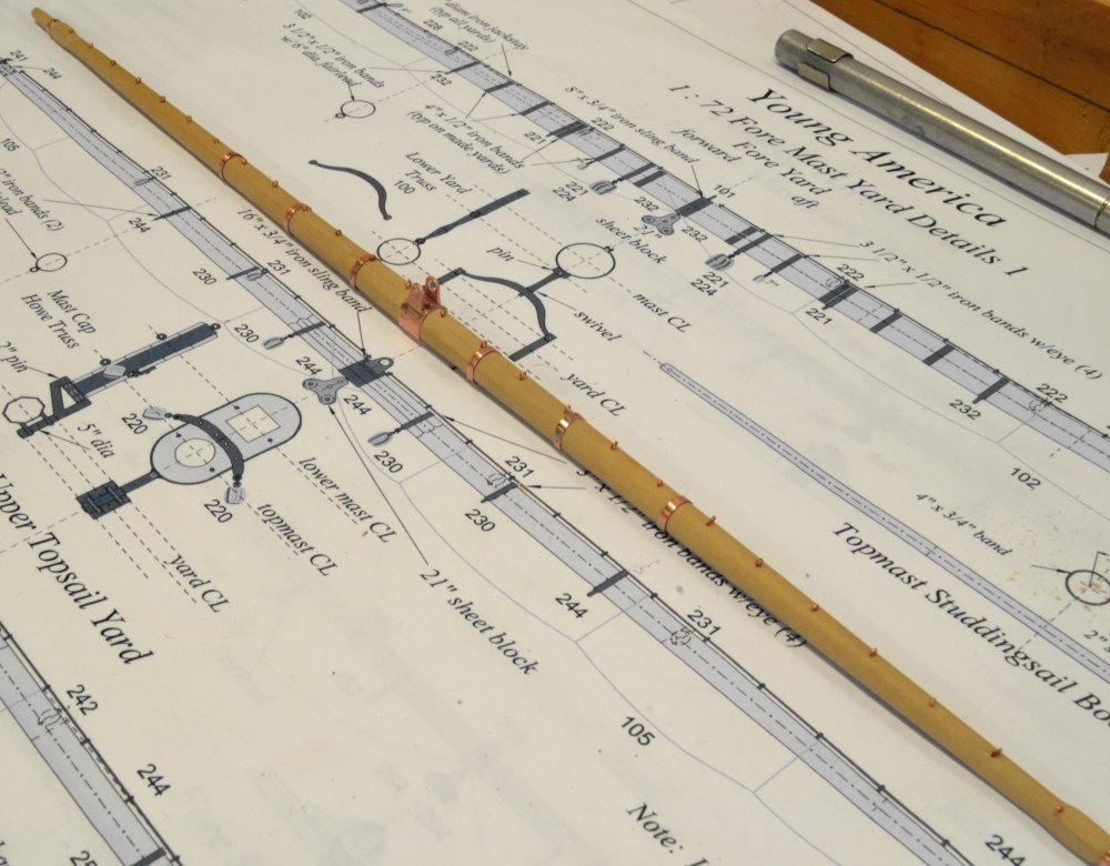
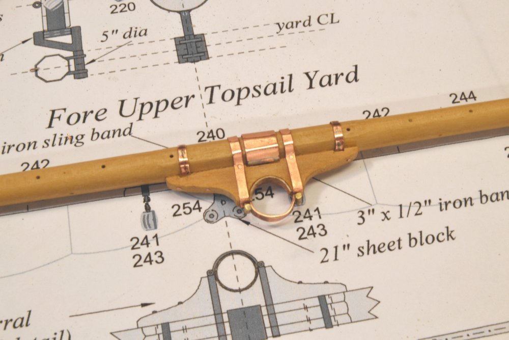
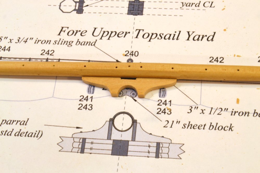
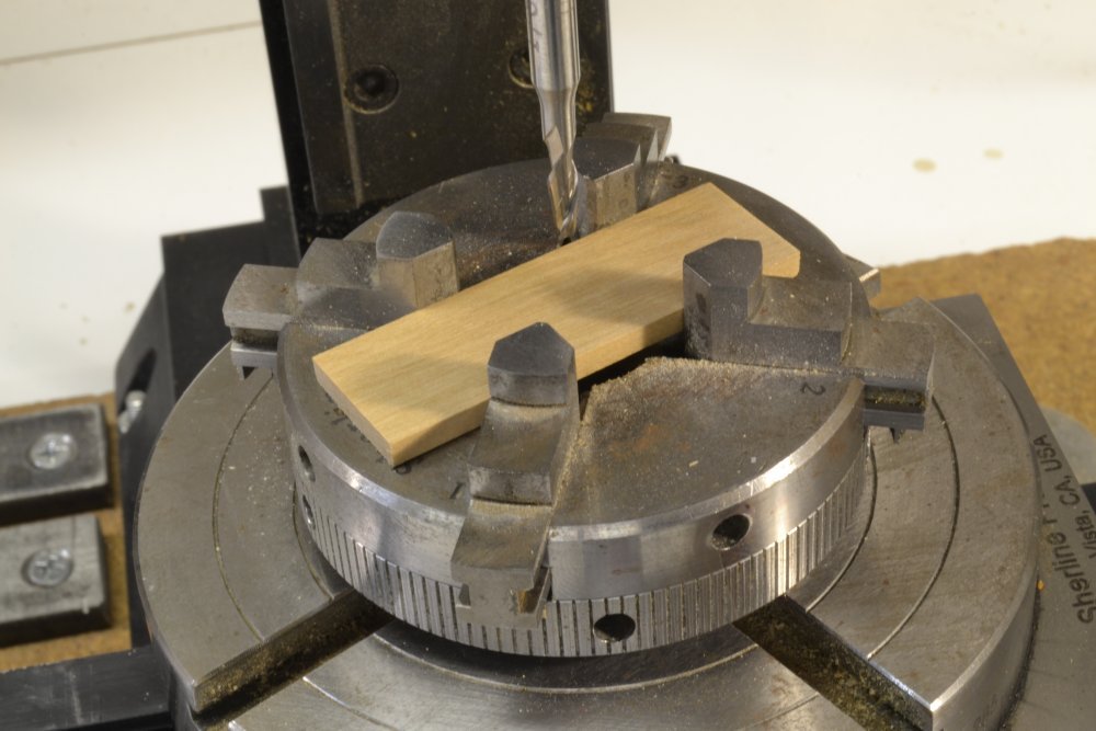
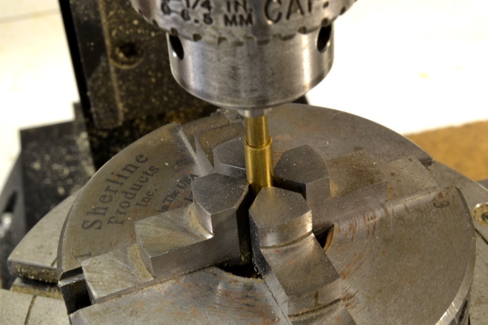
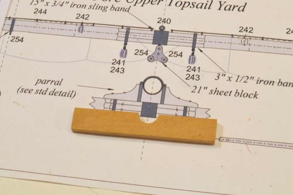
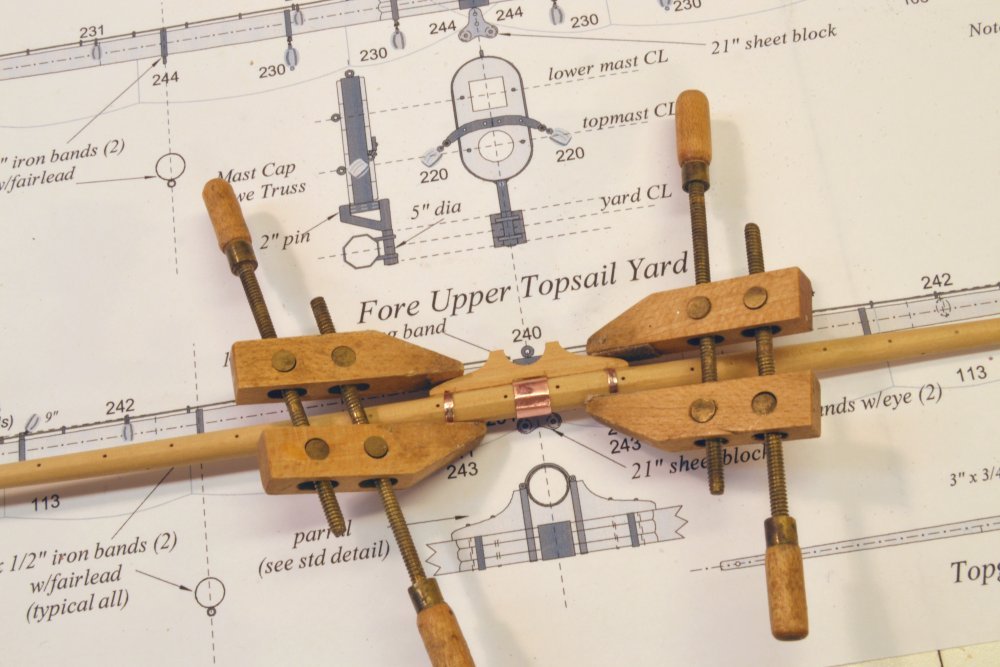
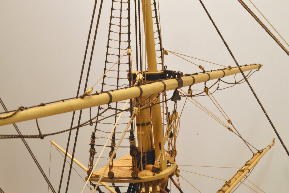
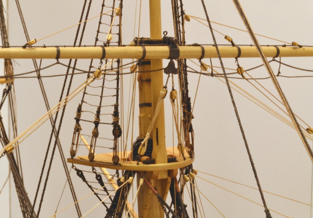
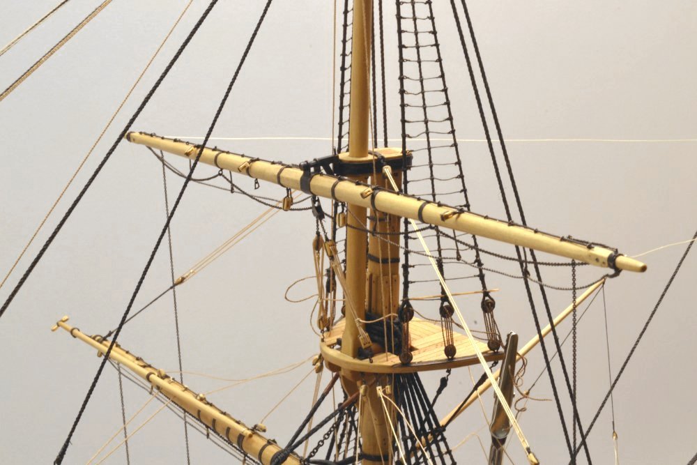
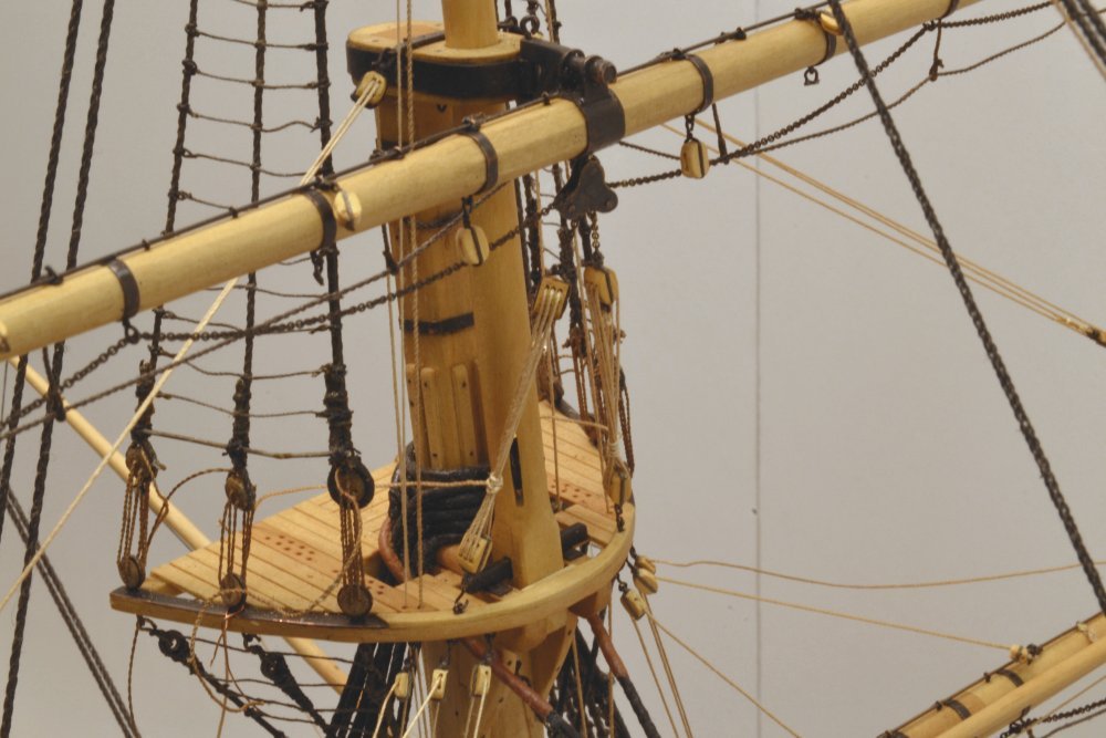
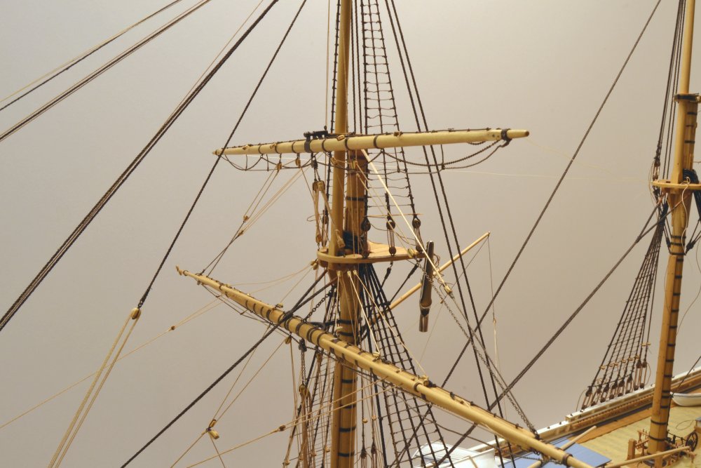
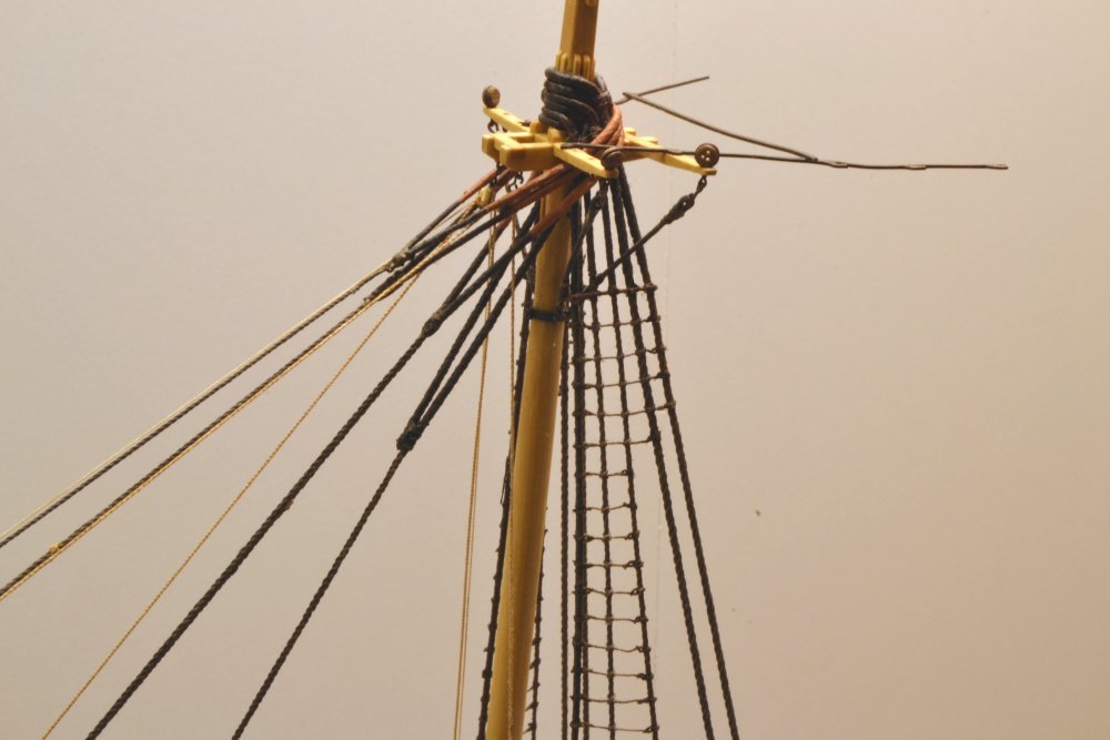
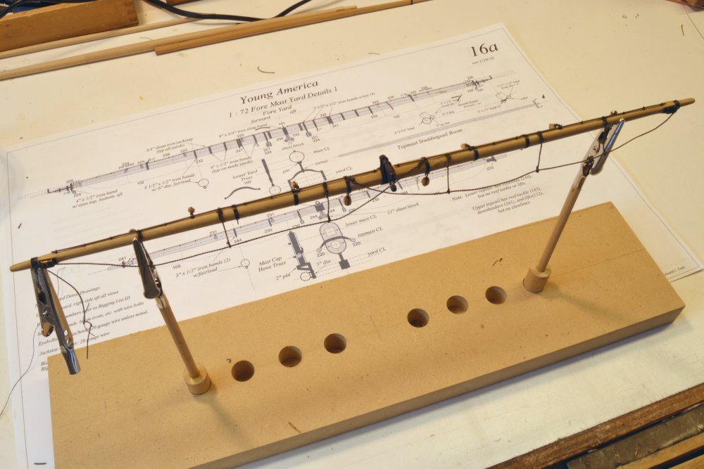
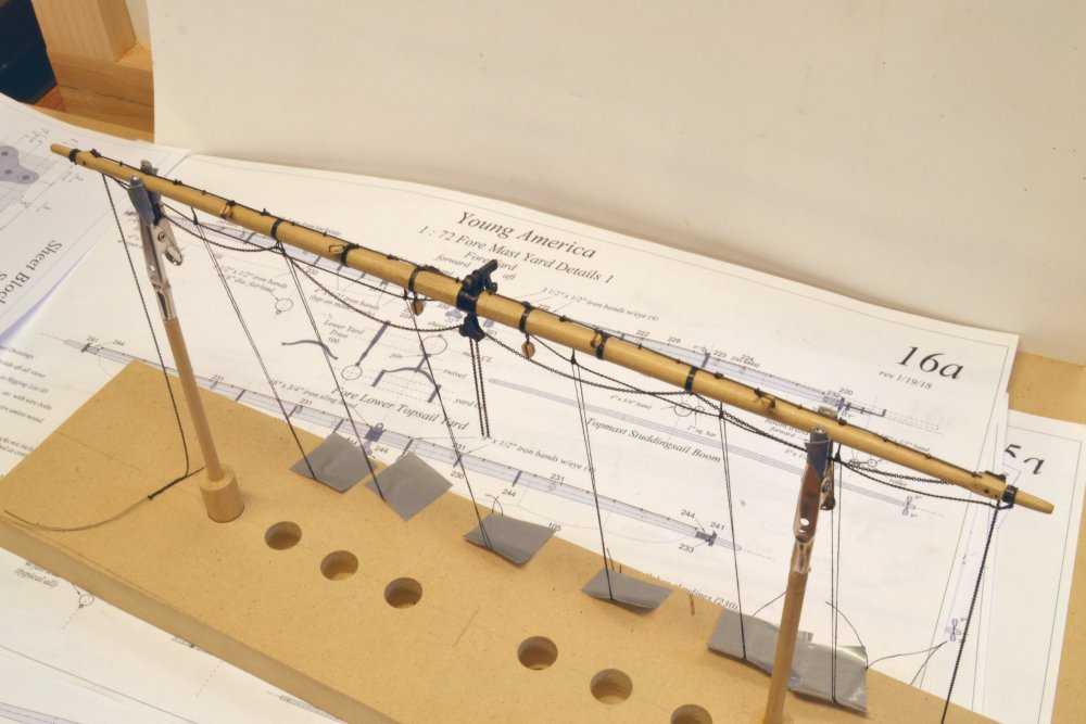
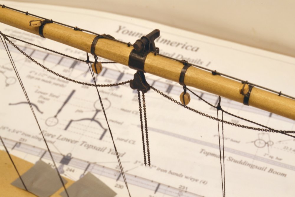
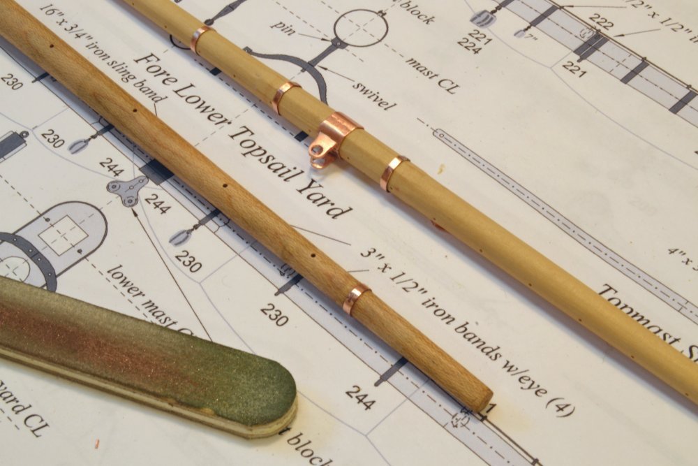
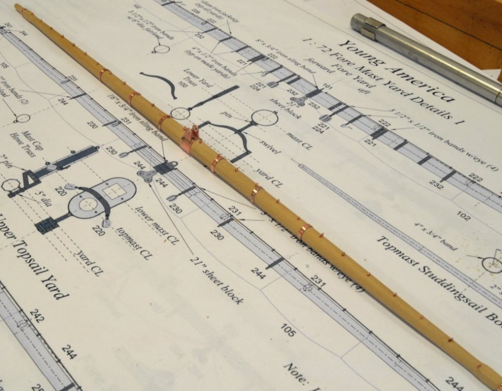
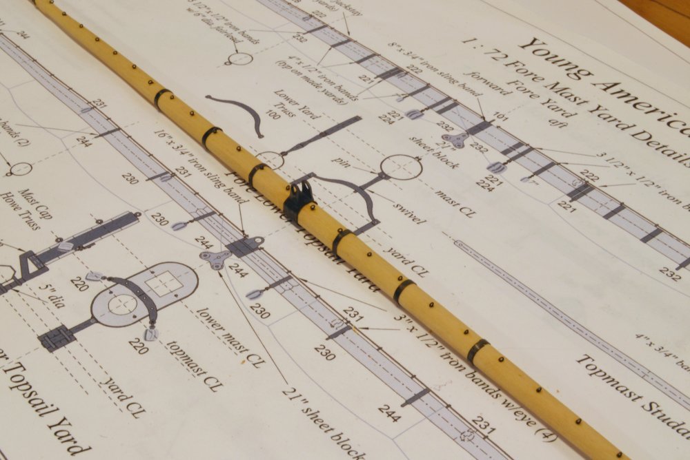
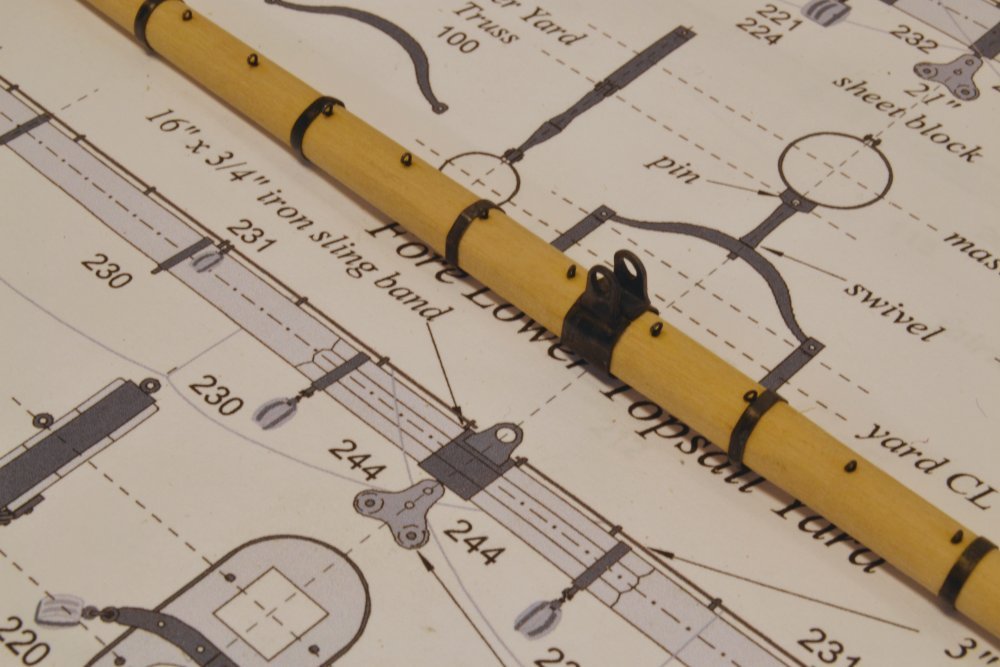
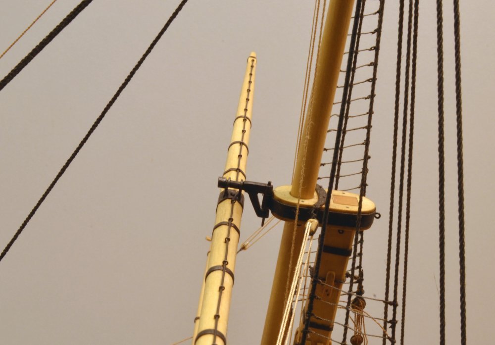
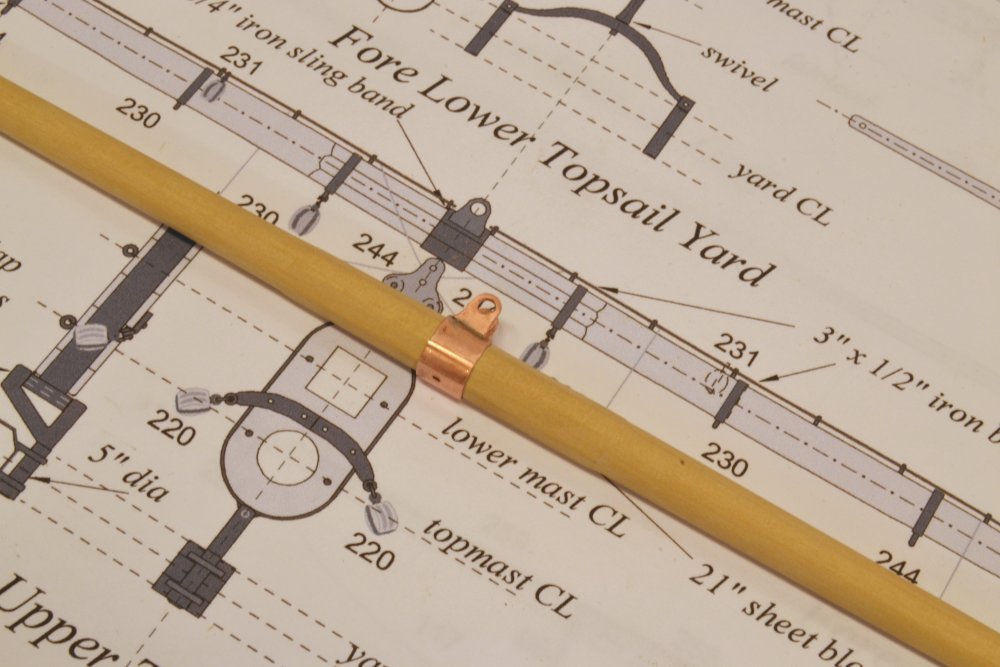
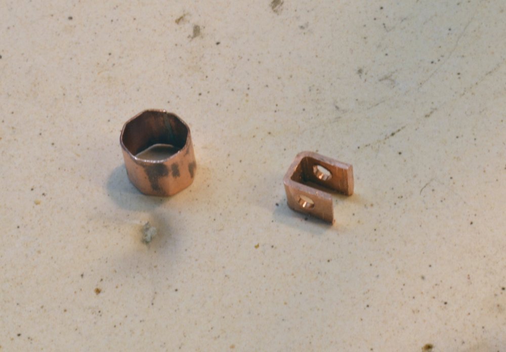
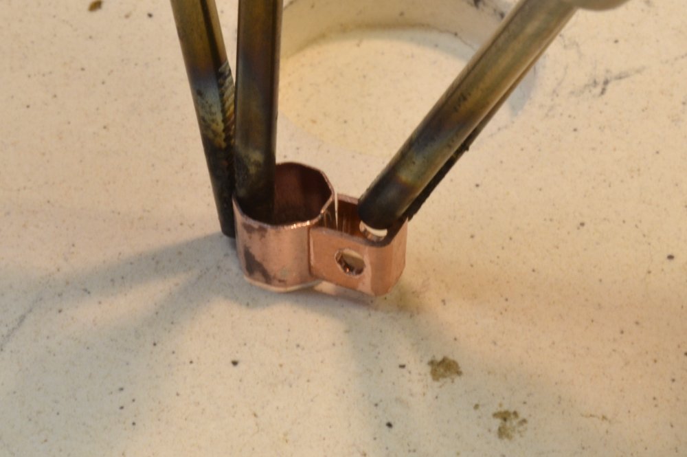
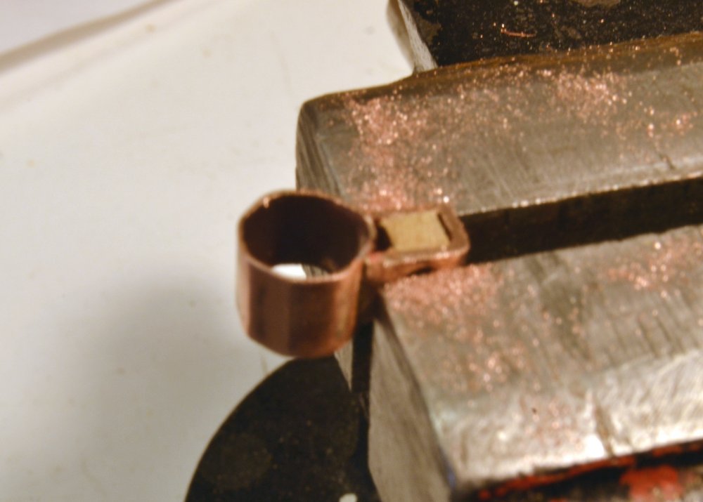
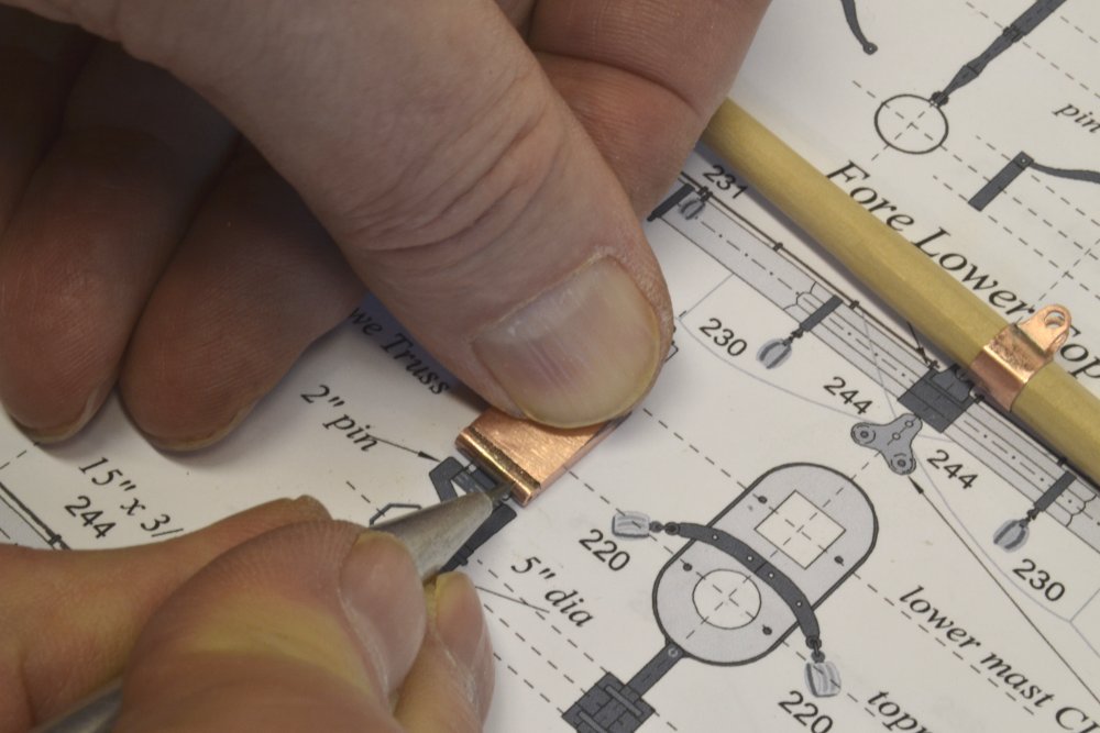
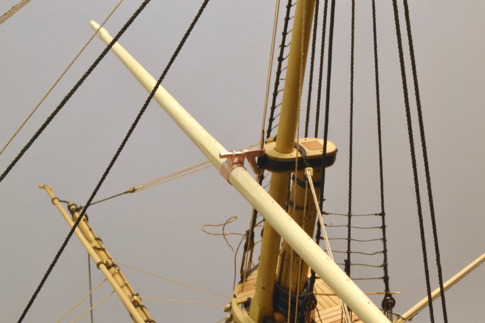
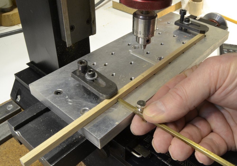
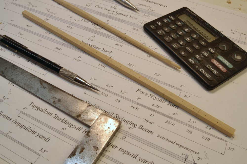
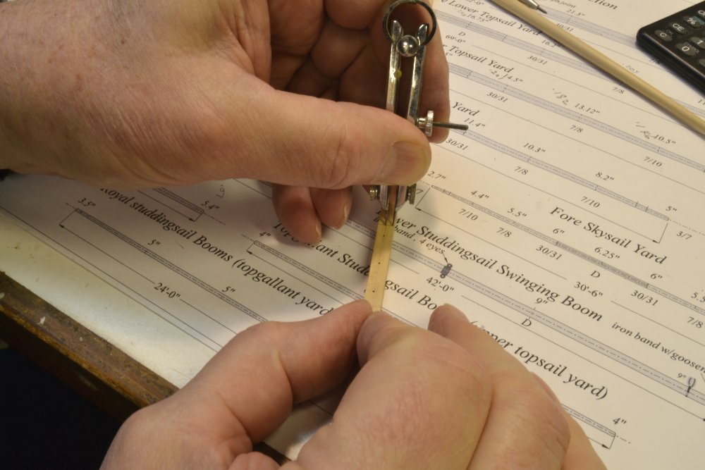
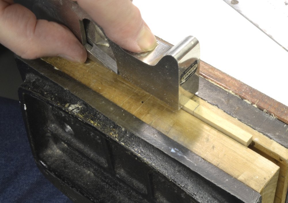
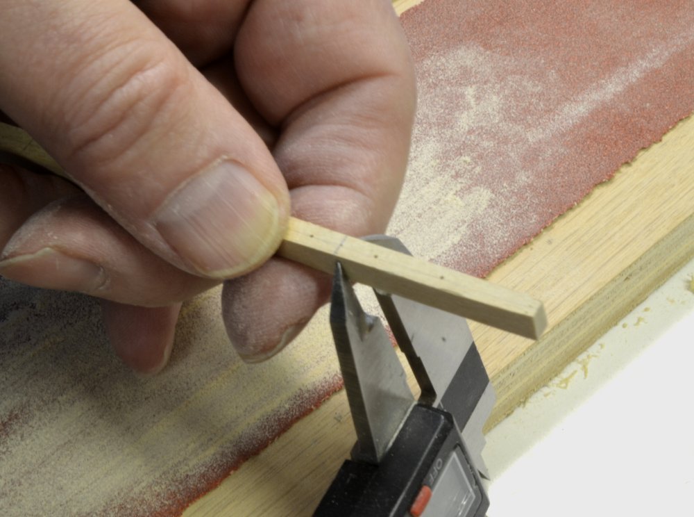
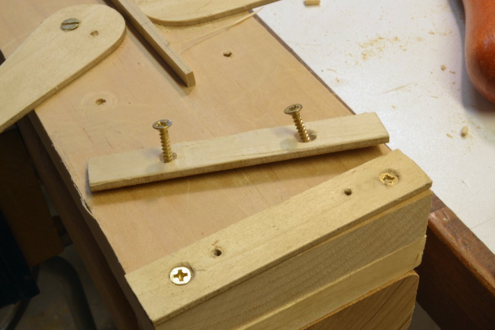
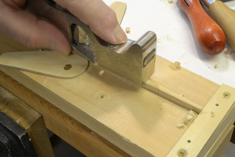
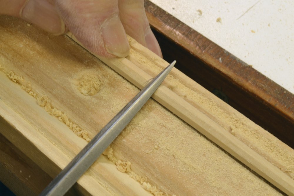
Young America - extreme clipper 1853 Part 268 – Fore Upper Topsail Yard Parral 1: Wooden Yoke All square yards above the lower topsails will be secured to their masts with parrals. These each consist of a wooden yoke bolted and strapped against the aft flat of the octagon at the center of each yard. The yoke is clamped to the yard by means of a hinged strap. The first picture shows the finished, but as yet unblackened, parral assembly fitted to the fore upper topsail yard. The picture also shows the center sling band, the bands for quarter blocks and the holes drilled for the jackstay eyebolts. This part describes only the modeling of the wooden parral yoke. You will note in the picture that the inside of the mast opening is lined on the wood face. The lining of the hinged clasp will be done later. The next picture shows the wooden yoke before assembly. The yoke has been notched for the sling band, but not yet for the two quarter bands. The wooden yokes could be shaped manually, but more precision in the circular opening may be obtained by boring the opening using the milling machine fitted with a rotary table. Starting with an oversized wood blank, the circular opening of the yoke was bored first, followed by rip sawing to yield a half circle, then sawing the base, and finally shaping the curved sides. The circular opening was bored using the setup shown in the next picture. The four jaw chuck conveniently centers and holds the piece. For modeling, the diameter of the opening will be 2" larger than the topmast diameter at the lower cap. This allows 1" for lining and 1" clearance. In practice, these allowances were more like a total of 1½" – ¾" for leather lining and a ¾" gap. The bore was made by centering a milling bit on the rotating table, offsetting the bit to cut the correct ID (= hole radius – bit radius), lowering the running bit through the piece and rotating the table a full 360 degrees. The resulting bore was very precise. Centering the table on the mill spindle using the normal dial indicator method can be a tedious task – a lot of work for this single bore. The setup shown in the next picture simplifies and speeds up this task and yields sufficient accuracy for these borings. The method uses two short lengths of close fitting telescoping tubing. The larger size is clamped in the four jaw chuck mounted on the rotary table. The smaller tube is chucked in the spindle. The X and Y tables are then adjusted until the tubes fit together smoothly as shown – centering the table. This is most easily done using the sensitive drilling attachment, which is then replaced by the milling chuck. In the next picture, the yoke has been sawed to yield a half circle for the opening. To accurately make this cut, the depth of wood below the bore was measured. To this was added one-half the bore diameter. Digital calipers were then set to this dimension and used to set the rip fence on the saw. After cutting the half circle, the rip fence was reset to the full depth of the yoke and the base excess sawed off. The curved faces of the yoke were then cut out on the scroll saw and finished with files/sanding. The notches for the bands were then filed out and the yoke glued to the yard as shown in the next picture. You will note that the banding shown on the drawings in some of the photos was later corrected. Fitting this banding and making the hinge/clasp will be described in the next part. Ed
- 3,618 replies
-
- 35
-

-
- young america
- clipper
- (and 1 more)
-
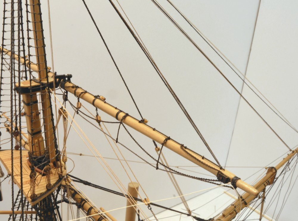
Thanks for all these comments and likes. I judge these blocks to be adequate for a model of this scale and scope. For some silly reason I was thinking there were more of these when I was doing the design and thinking about an efficient production method. Silly, because I had the rigging list in hand months ago. When I did a final count to cut the tubing, I realized there were just three, but by that time I was on a track. Spoked sheaves and fillets on the frame were certainly doable with more work - but with the yards down on their lifts these will be tucked up under the cross-trees and not the most prominent items on the model, so they will do fine. Thanks again for the compliments - always a good way to start a day. The upper yard has now been made and I will start covering that in the next post. The new element there is the wood and iron parral that was also an interesting project. There will be 12 of these in all sizes on the upper yards. Ed
- 3,618 replies
-
- 3
-
-
- young america
- clipper
- (and 1 more)
-
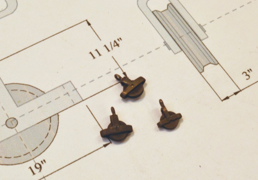
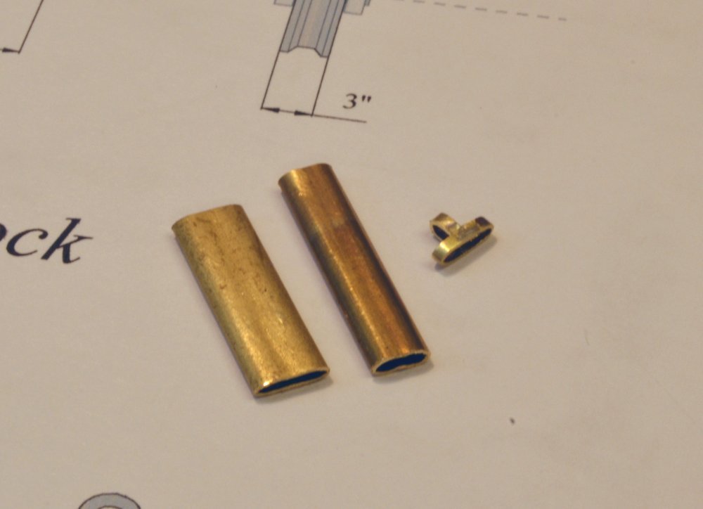
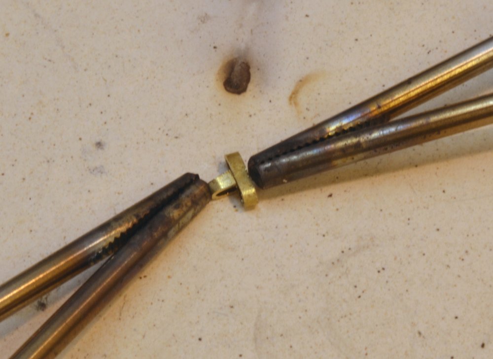
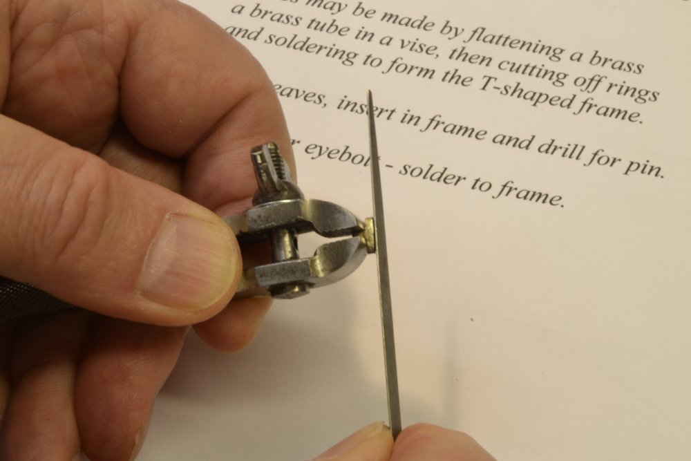
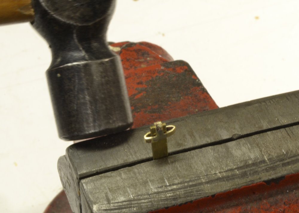
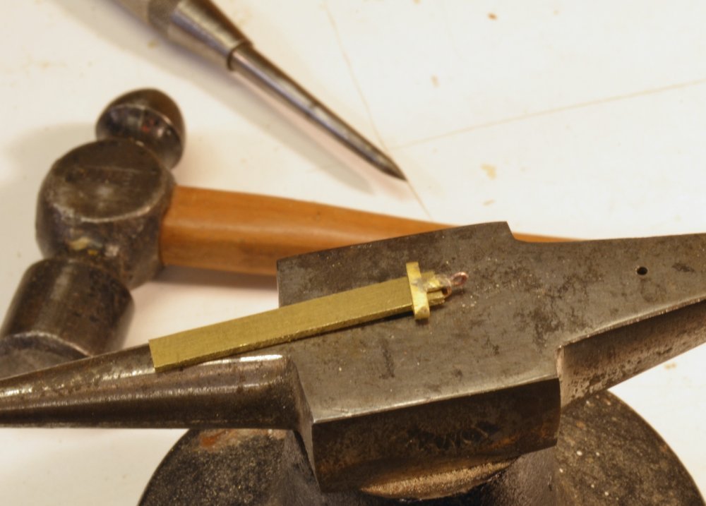
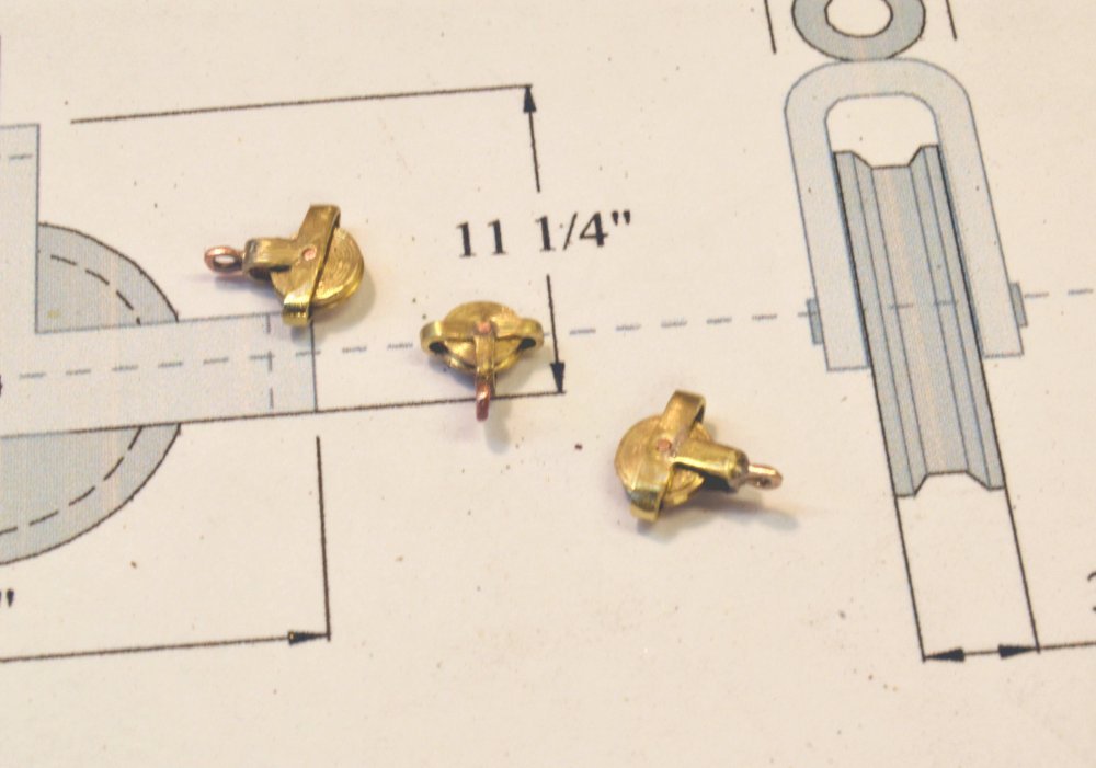
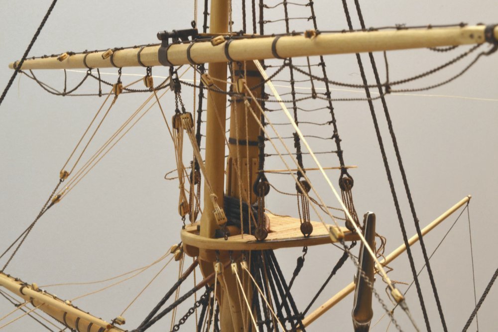
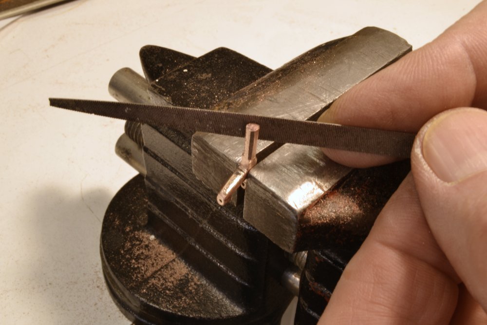
Young America - extreme clipper 1853 Part 267 – Halyard Gin blocks In preparation for work on the upper topsail yard, I decided to make the iron gin blocks for the halyards for all three of these yards. These are suspended aft of each topmast from a chain tye shackled to the central band on the yard. The tye passes through the sheave just below the topmast hounds. There is one of these iron tye blocks for each of the three upper topsail yards. They allowed the load of these relatively heavy yards to be distributed to both sides of the ship by means of tackles that will be described later. The heavy stationary yards below are supported by iron trusses as previously described, while those above have simpler, lighter halyard rigging. The first picture shows the three finished gin blocks. The blocks have inverted T frames that house iron sheaves and an eye at the top to attach the chain tye. Two have 12" diameter sheaves, one 10". The frames could be made from formed metal strips, but I chose to use flattened brass tube for these. The tube was flattened in a vise as shown in the next picture. Pieces were then sawed off and given some shaping to form parts for the basic two-piece assembly shown in the picture. It was then a simple matter to silver-solder these using the setup shown below. One side at a time was soldered. The frames were then further refined in size and shape as shown in the next two pictures. The brass strip holding the frame in the above picture served as an anvil to impart some squareness to the frames and to straighten the sides. The strip also allowed the frames to be center-punched for drilling without deforming the shape. In the next picture the eyebolt has been soldered into a small hole in the top of the frame and the sheave pin holes are about to be marked for drilling. A wooden spacer was inserted into each frame to avoid bending during rilling of the axle holes. The last picture shows the completed blocks before blackeneing. The sheaves were turned and drilled in the lathe from brass rod, then secured with peened copper pins. The assemblies were then polished, cleaned, and blackened using Brass Black®. Meanwhile, work progressed on the upper yard itself – next post. Ed
- 3,618 replies
-
- 48
-
-
- young america
- clipper
- (and 1 more)
-
Thanks, Maury. I'll have a look at it. Ed
-
Hakan, I took your good advice and put away the parts that were littering the deck. They will return later to be permanently fitted when the rigging permits. Thanks, Ed
- 3,618 replies
-
- 5
-
-
- young america
- clipper
- (and 1 more)
-
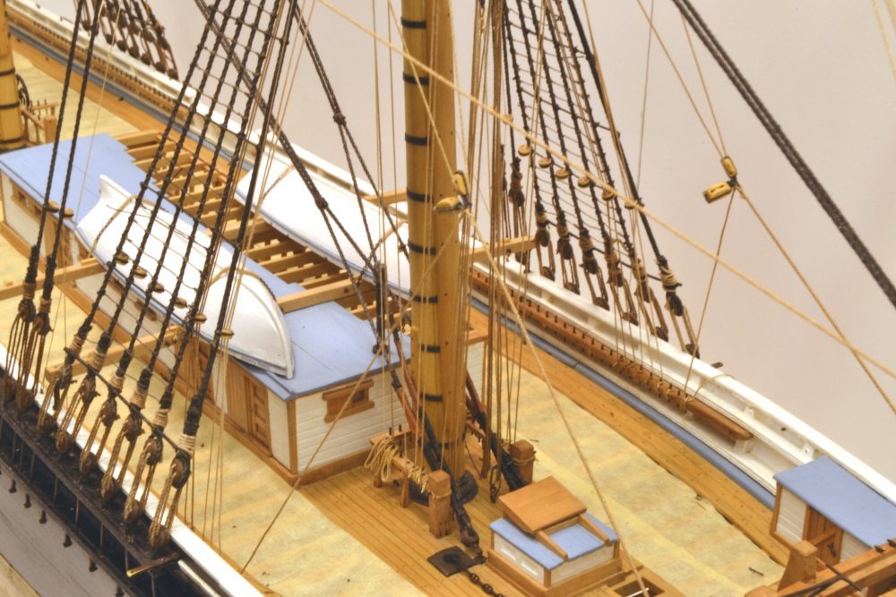
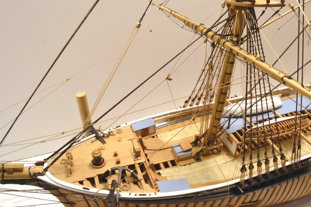
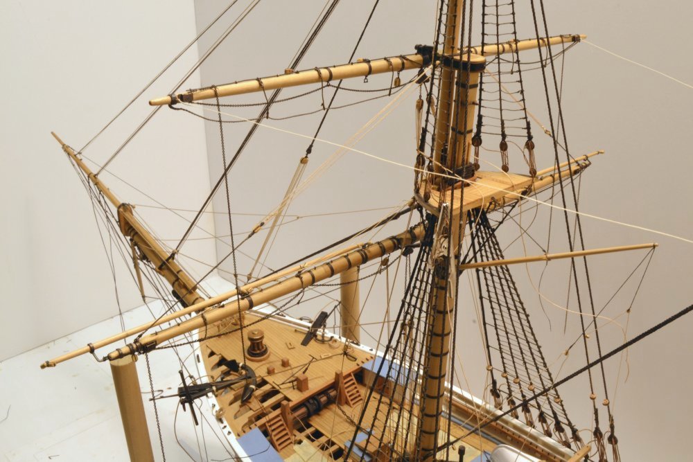
Young America - extreme clipper 1853 Part 266 – Fore Lower Topsail Yard Continued Apart from the braces that will be installed later, the last items of rigging on the lower topsail yards were the buntlines. There are two on each side. In the absence of sails these are stopped at the buntline blocks on top of the yard as shown in the first picture. Buntlines are normally passed through blocks on the underside of the tops or crosstrees at the head of their associated mast, but with the addition of the second topsail yard, the lower topsail buntlines are rigged through double blocks seized to the forward topsail shrouds as shown. The starboard side is shown in the next picture. From these double blocks the lines run down through fairlead holes in the top, inside the shrouds, through the fairleads on the #2 shrouds, and are belayed on the main pin rail on each side. These lines may be seen passing vertically down from the shroud blocks through the top in the next picture. The lower ends of these lines may be seen belayed at the side in the next picture. You may note that in these pictures the shroud lanyards have been re-wrapped above the deadeyes. These were unwound earlier to re-tension the shrouds and backstays as mentioned in an earlier post. The running rigging of the two lower yards has also been tensioned, secured at the pins with some dilute glue and the excess line clipped off. The clutter of these unsecured lines on the deck and above was becoming an unsightly nuisance, so it was time to get everything neatly secured. The next picture shows the forward deck cleared of excess rope. One of the next steps will be to make and add rope coils at the belaying points. The lower yard tacks and lazy tacks are still only temporarily belayed until the sheets are rigged later. Ed
- 3,618 replies
-
- 40
-
-
- young america
- clipper
- (and 1 more)
-
Frank, I have to apologize for being AWOL from your past few posts - my loss. The work on the dredge gear is exceptional and quite beautiful - a major achievement and one I am sure you are proud of. Congratulations on this fine work. Ed
-
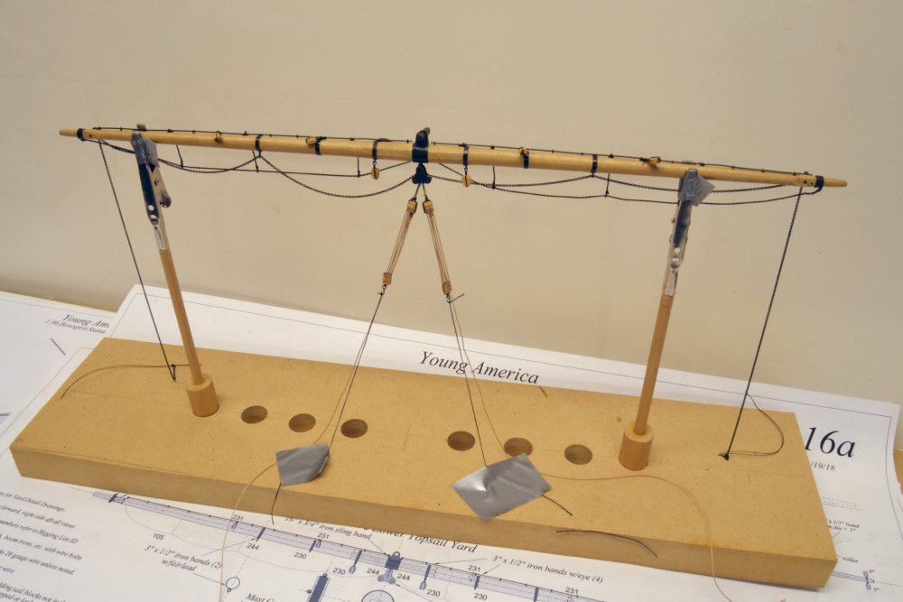
Young America - extreme clipper 1853 Part 265 – Fore Lower Topsail Yard Continued In the last part the upper topsail sheet chains were threaded through the blocks under the center of the lower yard and the outer blocks. The yard was then hung by the crane on the lower mast cap as shown in the first picture. The yard was braced temporarily back to the main top to keep it square. In the picture the twin triple-purchase sheet tackles have been rigged and secured at the forward rim of the top. The upper topsail sheet chains are hanging from the ends of the yard. The next picture shows the two tackles from the port side. As mentioned in the last post, the upper topsail was not clewed up for furling, so there are no upper topsail clew-lines. The sheet chains and the tackles are short – used only to fine tune the sheets under sail. These are short enough so that the upper topsail may be sheeted to the yardarm without fouling the tackles. The next picture is another view of these tackles. The falls are short on these overhauled tackles and simply hitched around each. The next picture from aft shows the yard with the two temporary braces back to the main cap. The next step was to rig the lower topsail clew-lines. These are shackled to the ends of the lower topsail sheet chains. Without sails the clew-lines are pulled up, overhauling the sheet tackles, positioning the lines for shackling to the sail when it is raised. The length of these sheet chains is limited by the height of the triple tackles below the main yard so the sail is able to be sheeted to the yardarm without the tackle becoming "block-on-block" or "chock-a-block." For this reason I raised the height of those tackles from their initial position. The difference in height is shown in the next picture. In the picture, the starboard block has been raised from its original height at the position of the port block in the photo. Both were then set at this upper height. This adjustment turned into a major, multi-day task, eventually requiring removal of the sheet block and the yard. I will not elaborate, except to say that getting things right the first time is preferred. The next three pictures show the clew-line/sheet chain rigging. The problem of shackling the clew-line/sheet to the sail is interesting. With the limitations described, it could certainly not be done from the lower topsail yard and the gear was probably not reachable by men on the top where other lines would be bent as the rolled sail was raised. Most likely this was done from the lower yard during raising. Whatever the method, it would have been easier than with a single topsail, where the lowest position of the yard would be even higher – above the cap. The next two pictures show the lead block arrangement for the clew-lines. The standing end of each line is seized to a thimble on a block hooked to an eyebolt under the yard. It then reeves through the block at the clew end, back through the block at the yard then through a single block at the quarters. From there it passes through a fairlead hole in the top down inside the #2 shroud and through its fairlead, to belay on the main rail. The next picture shows a view of this from aft. This picture also shows the stopping of the upper topsail sheet chain to the jackstay. Again, the length of the chain is limited by the length of the tackle. There are still a lot of loose lines cluttering these photos at the top and especially at the deck. I have delayed permanently securing these at the pins (fortunately) but it will soon be time to do this. Next, the four buntlines will complete the current work on this yard. All the braces will be left until much later for access reasons. Ed
- 3,618 replies
-
- 43
-
-
- young america
- clipper
- (and 1 more)
-
Steve, I am not sure I can answer your question definitively, but I can give it a try. Others may wish to comment. Channels on men-of-war were wide to provide space for working, fighting, and storage, but most importantly to maximize the spread of the shrouds and backstays. This wide spread added strength and safety for the masts. Channels were located at the height of major hull structural members to withstand the inward forces of the shrouds on the channels and hull. Channel width was not a problem in docking because these ships seldom docked. Merchant ships routinely docked. Closeness to the dock was important for cargo handling. For this reason clipper channels are narrow. Because of this, and to avoid shrouds and backstays being obstructed by the upper rails, the upper channels had to be raised above deck level (on ships with external channels) so that rigging would clear the rails. This placed the upper channel on toptimbers, well above the heavy structural members at deck level. I assume that the lower channels, usually at deck level, were added to spread the load to the lower hull members. It could also be that these lower channels protected the chains from damage against high docks at low tide or when the ship was fully loaded. Ed
- 3,618 replies
-
- 6
-
-
- young america
- clipper
- (and 1 more)
-
Micheal, I had to comment on your comment about the metal work. After seeing your work on the small engine - an other things - I doubt that there is much you could learn from me. Cheers - and thanks. Ed
- 3,618 replies
-
- 2
-
-
- young america
- clipper
- (and 1 more)
-
I checked your source. $3 for 6 sq ft is pretty tough to beat - and a lot less than I thought for this stuff. Can't imagine that the shipping is much. Thanks, Micheal. Ed
- 749 replies
-
- 4
-
-
- albertic
- ocean liner
- (and 2 more)
-
Guy, the wires on the sheet chains are temporary to allow me to thread them through the cheek blocks. Chain is very difficult to handle on its own. The chains hanging from the yard arms will be mostly cut off. The explanation of the short sheets in the last part should make more sense after the next post - I hope. Ed
- 3,618 replies
-
- 2
-
-
- young america
- clipper
- (and 1 more)
-
Young America - extreme clipper 1853 Part 264 – Fore Lower Topsail Yard Detailing I finally got the fore topmast ratlines installed, something I wanted done before mounting the lower topsail yard. The spreaders at the top of the yard continue to take a beating. Some protection is probably in order. At the top of the shrouds the ratline extend across the backstays. The next picture is a closer view. The next picture shows the fore topsail yard with footropes, quarter blocks and buntline blocks installed. In the next two pictures the yard has been temporarily mounted using the permanent pin in the crane. In the next picture the yard has been returned to the holding fixture for further work. In this picture the footrope stirrups have been pulled straight for stiffening and the chain upper topsail sheets have been threaded through the cheek blocks, under-yard fairleads and the central sheet block. Below is a closer view of the sheet block. The fabrication of this block was described earlier, as was the linking of the two chains inside the block so the sheet tackles could be used to keep the yard down. In the next picture these tackles have been rigged and shackled to the chains. The upper topsail sheet chains are short and those shown will be cut back later. The upper sail was taken in by lowering the yard and not using clue lines as was typical for the other yards, so there was no need for the sheets to be hauled up when furling. The tackles were thus used to take up slack in small adjustments. The short tackles shown will belay in the foretop – in the next post. Ed
- 3,618 replies
-
- 45
-
-
- young america
- clipper
- (and 1 more)
-
HMCSS Victoria 1855 by BANYAN - 1:72
EdT replied to BANYAN's topic in - Build logs for subjects built 1851 - 1900
I think attaching this with eyebolts is a safe bet, Pat. I can't imagine what the multiple loops on Jyland are for - decorative? allowing for progressive release if the rudder unships? They are attractive. Ed- 1,013 replies
-
- 2
-
-
- gun dispatch vessel
- victoria
- (and 2 more)
-
Roger, the braces control the rotation of the yard about the mast. My guess is that the yard is kept "level" under sail by the sail being sheeted down. This would be true of all upper sails when set and the lifts slackened by raising the yard. These lower topsails would almost always be the last sails furled. The yard is also fitted with two downhaulers that are secured at the yardarms, pass upward to blocks at the upper topsail yardarms, then to the center and down to the deck. Their purpose was to assist in lowering the upper yard, which might not always come down of its own weight especially when the ship was heeled. These lines would stabilize the yard, I presume. Pat, I do routinely check Nares as well - and quite a few of the usual others, of course - Steel, Lever, Rees, Lees - and then Underwood, Campbell, and Crothers. Apart from the descriptions and compilation of details needed to build the model, I don't expect any groundbreaking research. You are right about this taking time away from other things, so one must make choices, but unless you are following someone else's drawings, there is not much choice about doing research - as you well know from your current work. One book I would highly recommend is John Harland's Seamanship in the Age of Sail, 1984. Ed
- 3,618 replies
-
- 5
-
-
- young america
- clipper
- (and 1 more)
-
Pat, I did some further checking on the support for the lower topsail yard. If you have Underhill, you may wish to check p. 103: He describes slings and struts on large steel barques then "...however, in the greater majority of ships the lower topsail crane was strong enough to support the yard without assistance." You will see that there is more on this in chapter 2 on steel yards. Fincham (1843) predates the double topsail. Nothing in Kipping (1864) or Luce (1868). There is no end to checking this stuff. Ed
- 3,618 replies
-
- 3
-
-
- young america
- clipper
- (and 1 more)
-
Hi Pat, I have seen diagrams showing a strut under the yard to a band around the masthead to provide additional support. This may have been used in some cases but there is no sign of this on the Young America photos. A chain preventer would have to be attached to the topmast above the cap - not a likely arrangement, or at least not one I have seen, but I guess possible. The strut would require a different arrangement for the upper topsail sheet blocks, but that is not a major problem. Worth some checking of photos. A check on the strength of the truss/crane/cap band assembly might be useful. I would need a major refresher to do this calculation and have no idea of what the yard loading would be. I will check my inbox. It has filled up a couple times. Ed Later: the inbox was full, Pat - emptied it.
- 3,618 replies
-
- 2
-
-
- young america
- clipper
- (and 1 more)
-
Sailor, thanks for your comment. The basis for the model crane/truss is Underwood, Masting and Rigging.... Plates 6 and 16. These show scale drawings of the parts. The shaft and crane cross-sections are about 5". The 69' long, fore lower yard diameter is 16.75". This device is the sole support for the yard, which is without halyards or lifts. Ed
- 3,618 replies
-
- 4
-
-
- young america
- clipper
- (and 1 more)
-
Hakan, thank you. There is no problem soaking the spars and letting them dry. Warping occurs when the moisture is uneven - like on one side of a plank. Wetting does tend to raise grain on some woods, but this may be addressed by soaking before putting on the metalwork and then sanding off any raised grain. A second wetting will then not raise more grain. This pre-wetting and dry sanding is often used before applying water soluble stains to prevent sanding off the color if the grain is raised. There is very little grain raising on Castello or boxwood, so I did not find that necessary. Mark, thank you. That was precisely the reason. Topsails had grown to very large sizes and merchant crews were small. Navy crews were large due to the manning needs for gunnery. The large topsails were hard to handle even with a lot of manpower - especially in icey conditions. Doubling these topsails sail (and later the topgallants on some ships) allowed the same degree of reefing by taking in the upper sail only and lowering that yard accordingly. So the lower topsails have no reef tackle and no leech lines, and with the supporting truss and no need for topping, no lifts. Ed
- 3,618 replies
-
- 1
-
-
- young america
- clipper
- (and 1 more)
-
Young America - extreme clipper 1853 Part 263 – Fore Lower Topsail Yard Ironwork In the first picture some of the bands fitted to the yard. These were made from .010" copper strips cut to size for the yard diameter at each point, and then silver-soldered. The small diameter bands at the yardarms (not shown) were cut from copper tube. The tapered maple mandrel shown was used to stretch the band and test the joint, to recover the round shape that is lost in setting up for soldering, and to hold the band for buffing and polishing. The bands are then pushed over the yard into to position with a tight fit. All the bands on this yard will be fitted with eyebolts or fairlead rings, so all were center punched and drilled for this. The next picture shows the yard fitted with bands and jackstay stanchions There is no finish on the yard at this stage and with some care it has been kept clean. In the next picture the ironwork has been blackened using liver of sulfur solution. This was all done in one step to avoid any black smudging on the yard beforehand. The LOS solution was brushed over the yard. As the copper work on each section blackened, within a few seconds, the yard was rinsed under running water. It was then patted with paper towel and allowed to thoroughly dry. In the next picture the yard and ironwork have been finished with diluted Tung oil and allowed to dry overnight. The ¾" diameter iron jackstays were made from straight brass wire. This was treated beforehand with undiluted Brass Black®, then dried and buffed to remove residue. In the next picture the jackstay has been threaded through the stanchions and cut to size. The picture shows the assembled Howe truss temporarily pinned in place. I may do some further filing of the end of the shaft. The yard is retained with a tight fitting slit collar at the end of the shaft. The next picture gives a better view of the jackstays and the truss. The last picture shows the full yard on the mast. There are no studding sail booms on this yard, since the topmast studding sails are hung from the upper topsail yard and the booms for the topgallant studding sails are supported from that yard. The yard will now be removed to fit out its rigging connections and footropes. Ed
- 3,618 replies
-
- 42
-
-
- young america
- clipper
- (and 1 more)
-
Young America - extreme clipper 1853 Part 262 – Fore Lower Topsail Yard Truss When a double topsail (or double topgallant sail) arrangement was adopted, the lower yard position on the mast was fixed, and therefore this sail was not reefed. Any reduction in overall topsail area was done by taking in the upper topsail. Under the Howe patent, the arrangement most likely followed when Young America adopted double topsails in 1854, the lower yard was supported from the forward end of the lower mast cap by means of an iron truss that allowed the yard to rotate in two planes like the lower fore yard below. The first picture shows the installed sling band with a double bracket that will fit over a shaft on the truss itself. The band is pinned through the yard and the underside drilled for the sheet block eyebolt. The band is octagonal, made from .010" (about ¾" at 1:72) copper sheet. The band was soldered first. A U-shaped bracket was then formed from .015" copper, and drilled to accept the truss shaft. Both parts are shown in the next picture. The u-shape was used to assure that the bracket holes would line up after assembly. The joining top piece will be removed later. The next picture shows the two pieces being set up for soldering. After soldering, the assembly was set up in the vise as shown below to file off the end of the U and shape the brackets as shown in the last photo below. The U was formed over a wood block that was kept in place when the bracket holes were drilled. In the above picture a small piece of this block is inserted to allow the bracket to be clamped for filling. The truss itself is shown in the next few pictures. To start, two pieces of telescoping tube were soldered together then soldered to the top of a copper block that will be shaped to the truss configuration. Using tube avoids drilling aligned holes and assured a match with the hole in the mast cap boss. This initial assembly is being marked in the first picture. The truss was then cut and filed to its overall shape shown in the next picture where it has been temporarily mounted to check fit. In the next picture the truss shaft is being filed round.. In the picture the 5" shaft is being rounded from a sized square, to an octagon to a round – as was done in making the spars. In the last picture, the full truss assembly is temporarily mounted with the yard. The forward end of the truss shaft will be fitted with a retaining cap and cut off. This will be done later after the other yard ironwork is fitted. All will then be blackened and the yard given some finish as was done before. You may note in this picture that the ratline work on the topmast is still in progress. Ed
- 3,618 replies
-
- 35
-
-
- young america
- clipper
- (and 1 more)
-
Good suggestion for improvement, Guy. Ed
-
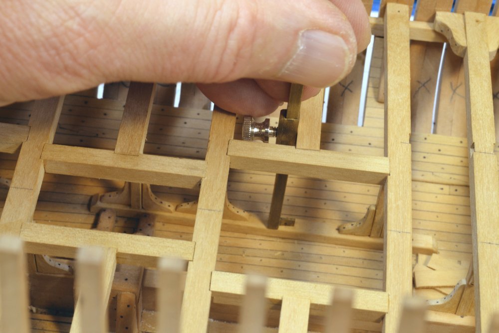
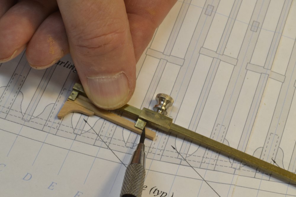
Thanks, everyone. Two weeks between posts seems like a long time. It has been good to get back to some sawdust for a change. Wefalck, I started looking through the posts for the height gauge but decided looking through the photo files would be easier, so here are two pictures. It is a simple device made from some square telescoping brass tube. The inner tube is 1/8". The sliding outer section has a reinforcing strip soldered on one side to give more thread depth. This side is tapped for a 4-40 knurled screw. Square tabs are soldered on as shown at the ends. The primary purpose for this was measuring the heights between beams so supporting pillars could be cut to size. Works well for this and other simple tasks. Hello, Guy. Good to hear from you. Thank you for your comments. I hope that sharing the rigging work on YA will benefit builders of a variety of ships of the period. I can definitely say that the rigging work and therefore the posts on rigging will not be lacking in detail - some quite excruciating I'm afraid. Thank you, Pat. Not always as crisp as one would like, but I guess we are our worst critics. Cheers, Ed
- 3,618 replies
-
- 28
-
-
- young america
- clipper
- (and 1 more)
-
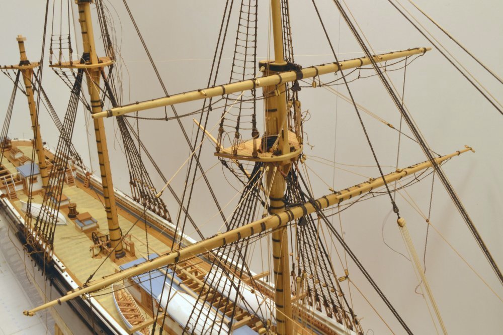
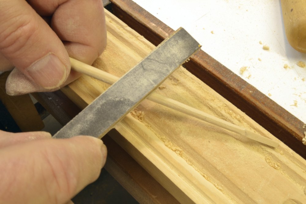
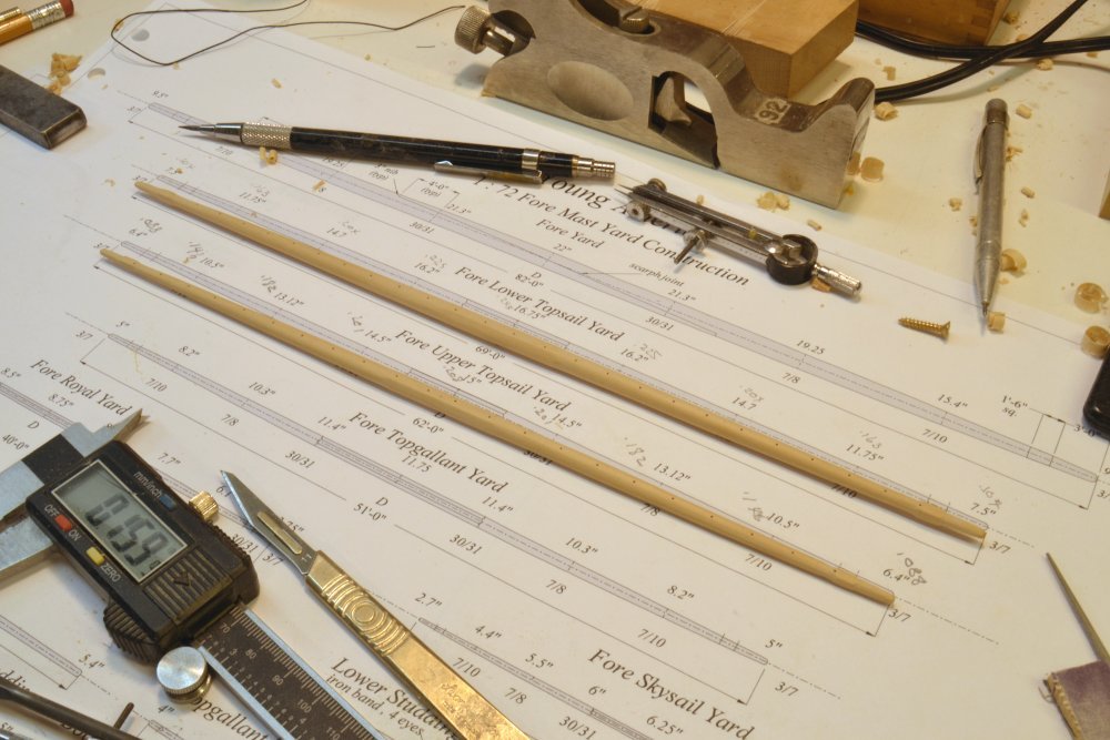
Young America - extreme clipper 1853 Part 261 – Fore Topsail Yards I have finally been able to break out of the ratline work to start on the next set of yards – specifically the fore lower and upper topsail yards. These will likely be the next two to go up, but the main yard is also an option. I want to get all the ratline work done on the lower and upper masts before staring on the yards. I got ahead of myself with the fore yard and that made finishing the ratlines a tougher job. I described the methods I am using to make spars in Parts 217-218 and Parts 247-248, so I will not go through it all again. I will mostly stick to some things that may not have been covered earlier. I generally like to drill all the holes in a spar at the first trim. At this stage it is sized but still square and not tapered, so it is easier to hold and center the piece. I forgot to do this on the lower topsail yard so it had to be done later as shown in the first picture. In the picture the holes for the jackstay stanchions are being drilled. The yard is clamped to the tooling plate at the octagonal center area and at the yardarm square section – not optimum but not too difficult. In the next picture the upper topsail yard is set up for drilling while still at the first trim. In the earlier description of this drilling I used the mill vise, but since I had the tooling plate set up I decided to use it instead. To make the yard parallel with the plate, I used the small depth gauge described back during the deck framing. The next picture shows the jackstay stanchion holes drilled into this yard. The stanchion holes are the most important to do at this stage because they need to be centered on top of the yard and equally spaced. Other holes will be drilled later. In the picture the quarters are marked out. In the next picture dividers are being used to mark the diameters on two opposite sides at each quarter. These are taken directly from the drawing and serve as guides for the first roughing out only. The final dimensions at each quarter will be measured and adjusted more accurately as shown below. In the next picture the two marked faces are being tapered using a plane with the yard clamped in a vise. The vise works well before the spar is tapered. The fixture described earlier and shown below could also be used. The taper is planed, scraped, rasped and sanded down to the divider marks. In the next picture calipers are being used to check and refine the sizing to the dimensions specified on the drawing. The drawings specify the diameter at each quarter in full size decimal inches, which are then divided by 72 to get the measurements to the three significant digits used in the final sizing as shown above. The sandpaper board is used for the final sizing. With the spar tapered on two sides, the planning fixture shown below was then used to taper the remaining two faces. For these smaller spars the top section of the stop was removed to clear the plane. In the next picture one of the remaining two sides are being tapered. The yard was then converted to an octagonal shape, except at the yard arms, as described in the earlier posts. The center area on these "single-tree" spars were left octagonal, so the final rounding begins at the end of the octagonal section as shown below. After filing off the corners of the octagon, the rounding was completed down to the square yardarm section using the sanding stick shown. This has 220-grit paper on one side and 320-grit on the other. The last picture shows the two topsail yards ready for their ironwork. Ed

- 3,618 replies
-
- 43
-
-
- young america
- clipper
- (and 1 more)
-
Hi Mark, I think that the important thing to keep in mind here is that the upper plank of the wale (as well as other topside planking and rails) follows the sheer line that is drawn on the sheer plan and that measuring heights up from the base at each frame line on that line will yield the correct line as drawn and probably as built as well, since shipwrights would likely mark the height of this line on the frames. These heights would be given in the tabulated data sent to the yard. This method would yield the reverse curve effect that Druxey describes. However, I would argue that this is not so much an illusion as it is the true line of the plank, since the heights of the sheer line on the sheer plan are not true lengths along the side of the hull. The distances between frame lines along the hull, especially at the bow, are greater than those shown on the plan - tending to flatten the curve in those areas. So, if you are building the ship "as designed" I would merely measure up from the base the heights on the plan at each frame and trust that to be correct. We could probably debate whether this method was always followed in the yard, or for that matter in the construction of models at the time. There might have been more of a desire to have a pleasing line in the latter case - and maybe even in the former. By the way, if you depart from the sheer line at the wale in the interest of aesthetics, you will need to adjust the planking above - or end up with a mismatch at the top. My recommendation would be: strict adherence to the drawing. Ed