EdT
-
Posts
2,214 -
Joined
-
Last visited
Content Type
Profiles
Forums
Gallery
Events
Everything posted by EdT
-
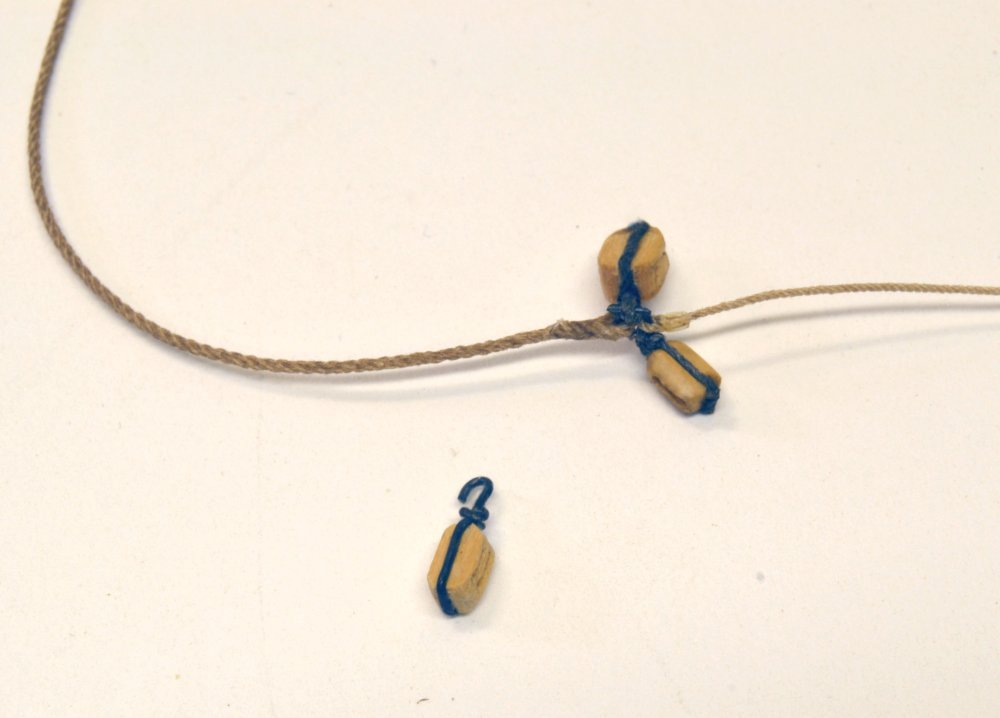
Thank you both for your comments and all others for the likes. Scott, the blue cast is due to an over-correction of the pictures color balance. Due to lighting differences (mix of florescent, incandescent, LED) in the workshop I need to normalize the color balance on most images to make them appear as they do by eye. Sometimes this results in the effect you see. The shackle, hook and iron strap are blackened copper. The other block strapping is made cotton rope dyed with india ink to a very dark grey. Here is a more realistic representation with some more careful adjustment - perhaps a little more vivid than real life but close to the right colors. Ed
- 3,618 replies
-
- 18
-

-
- young america
- clipper
- (and 1 more)
-
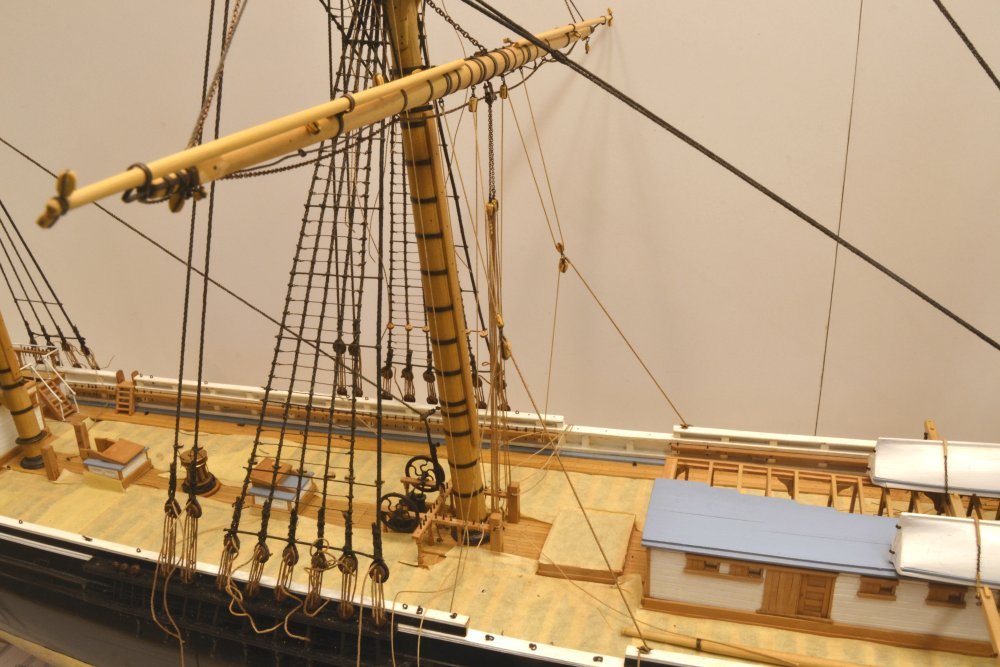
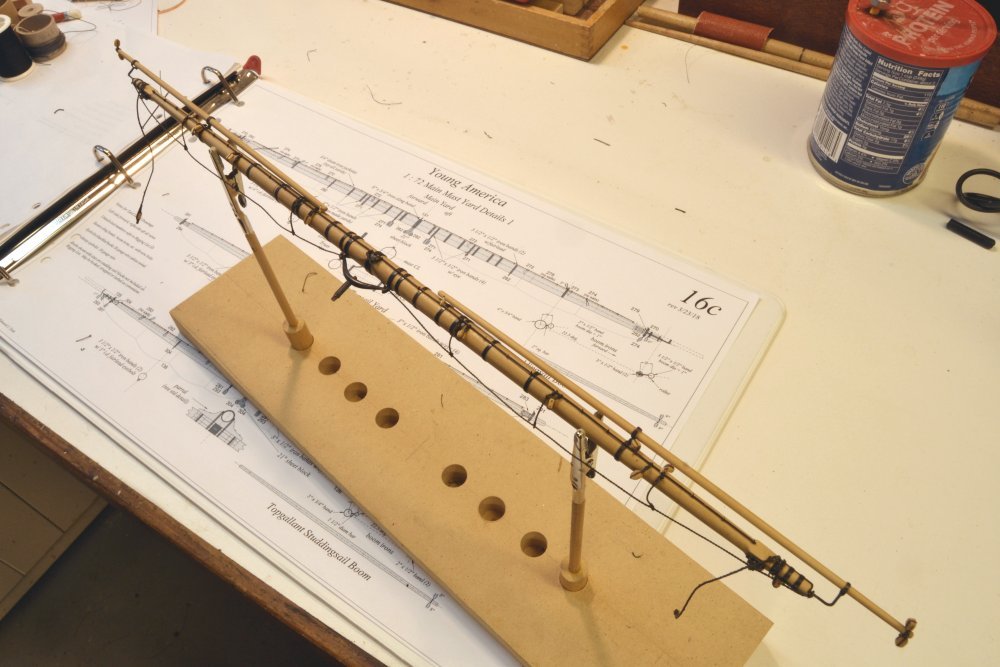
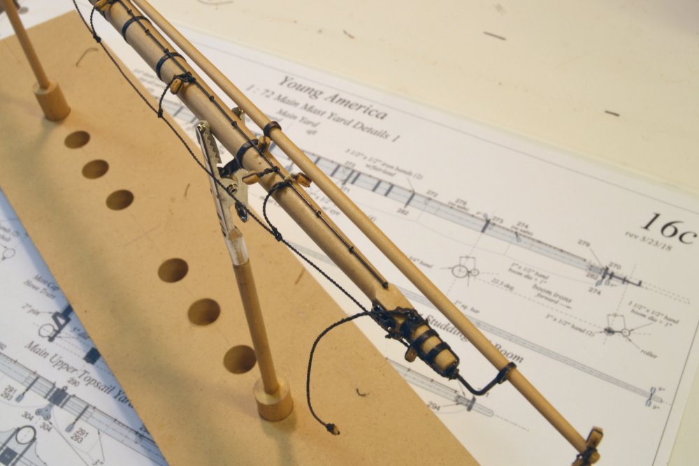
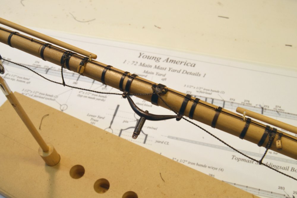
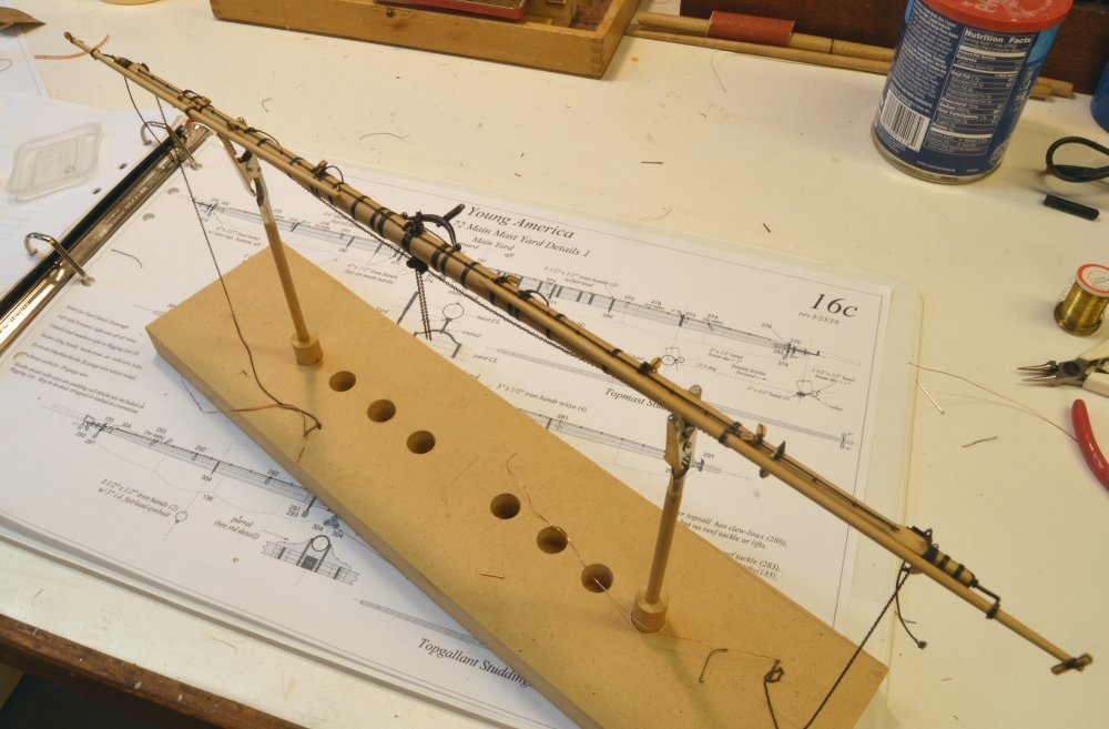
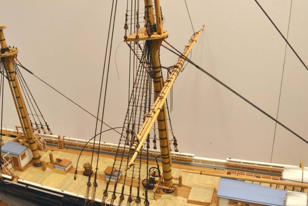
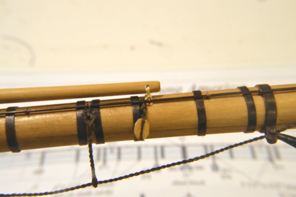
Young America - extreme clipper 1853 Part 281 – Main Yard Rigging 2 The first picture shows the main yard ready for the next rigging steps. The taut chain sling may be seen in this picture. The topsail sheet chains are hanging from the cloverleaf sheet block under the center of the yard. As described before, these chains are linked over the central pin within the block to allow them to pull down on the yard using the two tackles soon to be added. This also permits the chains to hang somewhat slack under the yard on their way to the cheek blocks at the ends. The two triple tackles for the sheets are shown rigged in the next picture. The lower blocks of these tackles are hooked to deck eyebolts just forward of the mast and the falls are belayed on the topsail sheet bits using the long horizontal belaying pins. The next items to be installed are the clue garnets with the main sheet blocks, tacks and lazy tacks attached to a single large shackle. The next picture shows the prefabricated gear for one side. The large line is the tack that was used to haul the weather side of the sail taut. The smaller line is the lazy tack, used to control the sail as it was switched from tacks to sheets while the yard was being braced when the ship tacked. The large block is the sheet block. The sheet will be added later. At this stage outboard rigging – mainly braces and lower course sheets – would be an obstacle to the work and subject to damage. The smaller attached block is for the clue garnet. The standing end of that line is shackled under the yard, passes through this block, back through one sheave of the quarter block and belays on the main fife rail. The hooked double block in the picture is a quarter block. The second sheave on this block takes the fall of the reef tackle. The next picture shows these lines rigged. The tacks are belayed on cleats on the bulwark rails and the lazy tacks to the first pins on the main pin rails. These remain unglued so they may be adjusted when the sheets are added later. In the next picture the topping lifts, buntlines, leechlines and reef tackle have been added. The next picture shows a closer view of these lines. The bunt and leech lines pass through single blocks hooked under the rim of the top, down through shroud fairleads and belay on the main pin rails. The reef tackle falls pass under the yard, through the aft sheaves on the double quarter blocks, and belay on the fife rail below next to the clue garnets. Next the bowlines. Ed
- 3,618 replies
-
- 41
-
-
- young america
- clipper
- (and 1 more)
-
Nicely done, Maury. Congrats on finishing a fine model. Ed
- 525 replies
-
- 1
-
-
- anchor hoy
- hoy
- (and 1 more)
-
Magnificent, Amalio. Ed
-
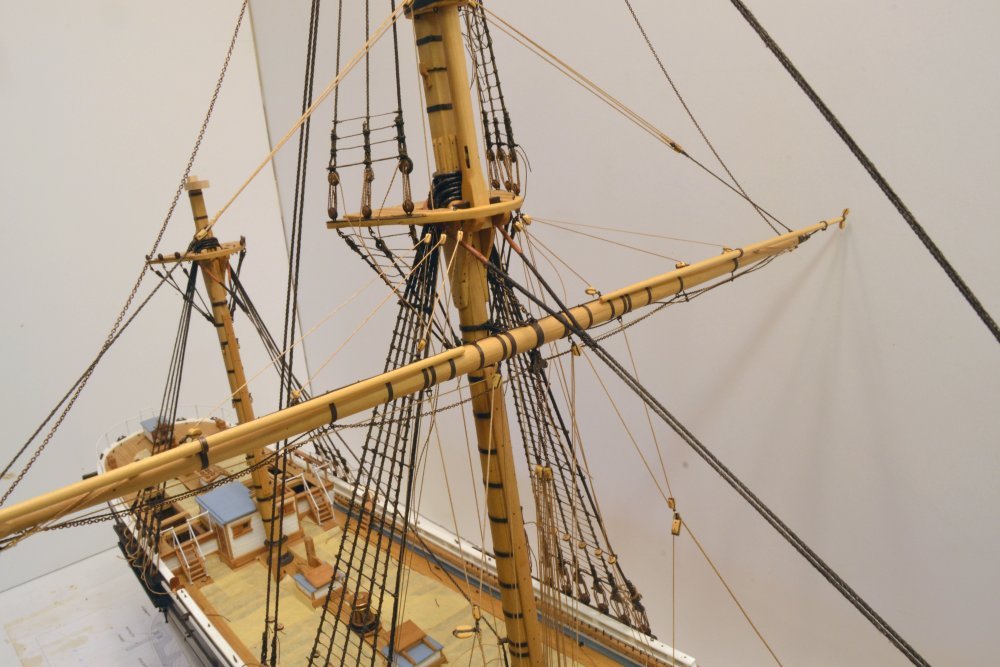
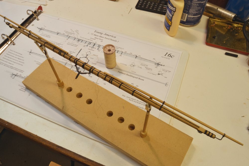
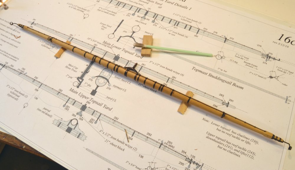
Young America - extreme clipper 1853 Part 280 – Main Yard Rigging 1 With the studding sail booms mounted, the next step was to attach much of the rigging at the workbench. The first picture shows this bench work in progress. The yard is mounted in a simple holding fixture for this work. After some experimenting, the holding clamps are now lined with molded epoxy resin jaws. The first step was to hang the footropes and stirrups. The topping lift pendants may be seen dangling from the ends. Also, most of the blocks have been lashed on in this picture. The next picture shows a closer view. The lashing of the footropes to stanchions on the opposite side of the yard near the center is shown in the next picture. In the last picture, the lower topsail sheet chains have been threaded through the sheet block under the center of the yard and out through the fairlead irons and the cheek blocks at the ends. The last item to be fitted after this picture was taken was the center sling chain. This may be seen in the last picture that shows the yard connected to the mast. The sling chain was pre-measured and shackled to eyebolts at each end. One was pre-fit to the central yard band. After hanging the yard, the mast was then marked and drilled for the other eyebolt so the truss would be horizontal. Ed
- 3,618 replies
-
- 37
-
-
- young america
- clipper
- (and 1 more)
-
Thank you, Scott. Yes the footropes and stirrups on the model are rope - as I said, in this case two-strand linen. Three-strand would be better, even at some compromise on size. Ed
- 3,618 replies
-
- 2
-
-
- young america
- clipper
- (and 1 more)
-
Thanks for the comments. Slackwater, I made these over 20 years ago and appear to have used 7/64 rod. The outer diameter of 4-40 threads measures pretty close the the diameter on my drawing. I may have turned the rods, but cannot remember. Sorry I can't help with a source. I believe K&S makes 2.5 and 3mm rod. May be worth a try. Guy, the appearance of the footropes in closeup photos is a problem. It does look like twisted wire. It looks much better in real life but maybe that is my eyesight. My choice of rope formula for the these is one of my regrets. These are two-stranded linen rope. Two stranded rope is Ok at smaller sizes and if tightly wound, but that shown on the 4 1/2" footropes it is less than ideal. I did not have a three-strand formula for any sizes of linen - my choice for standing rigging. In retrospect I should have used my three-strand cotton formula for these and have actually contemplated replacing them with that. Not an inviting prospect, but it could be done. I am sure there were different ways to attach stirrups. I followed what I believe was standard practice of the time. The stirrups are made with a spliced eye (no thimbles at this size) at each end, to a standard length of 3'6". The upper eye is lashed to a jackstay stanchion and the footrope passes through the lower eyes. I believe I showed how the stirrup eyes were made in an earlier post (Part 254). The inner end of the footrope is lashed to a stanchion on the opposite side of the yard and the outer end is an eye over the yardarm or boom iron. Ed
- 3,618 replies
-
- 2
-
-
- young america
- clipper
- (and 1 more)
-
Thanks for these comments and likes. Mark, the fastening you refer to is the heel lashing. It was made with a short length of rope between an eye or a hole in the boom to the jackstay or one of its stanchions. I believe topmen routinely carried a collection of small rope lengths for various uses - as well as the knife mentioned by Wefalck and other items. The two most obvious temporary lashings on my model are the boom heel lashings and the tied-off reef tackle blocks. Others were used in the various steps of bending or unbending sail. To extend the boom, a boom-jigger tackle was attached to the inner end and to a point further out on the yard. The heel lashing was cut and the boom hauled out with that tackle where the inner end was again lashed down and the jigger removed. To retract, the process was reversed. In addition, when bending or unbending the yards' square sail, the studdingsail booms were unlashed at the inner end and that end hoisted up to clear the yard for the work of the yardmen. These types of temporary lashing were used routinely. Studding sails were used infrequently and eliminated altogether in the later clipper years when speed was less of an issue. Setting these sails undoubtedly required some acrobatic efforts at the outer ends of the yards, but this work would normally be done in mild conditions. As modelers, we do not often think much about the order of setting and taking in sail, but a definite order was prescribed. Studding sails would be the last to be set as the wind died to near calm and the first to come down as it picked up - unlike, for example, reefing topsails - the last step as gale forces developed. This process also required a lot of knotting of reef points. Iron men in wooden ships. Ed
- 3,618 replies
-
- 12
-
-
- young america
- clipper
- (and 1 more)
-
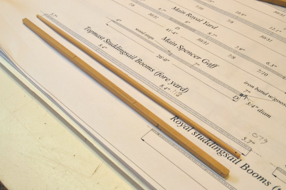
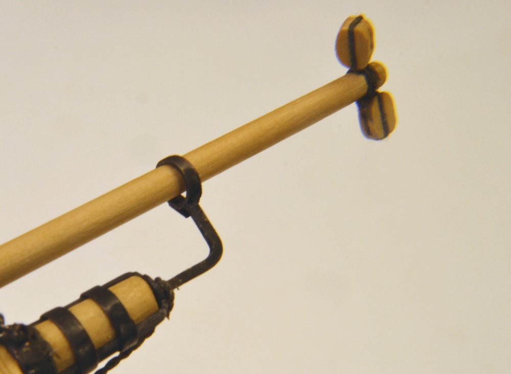
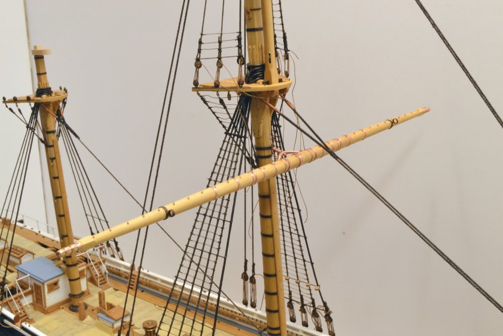
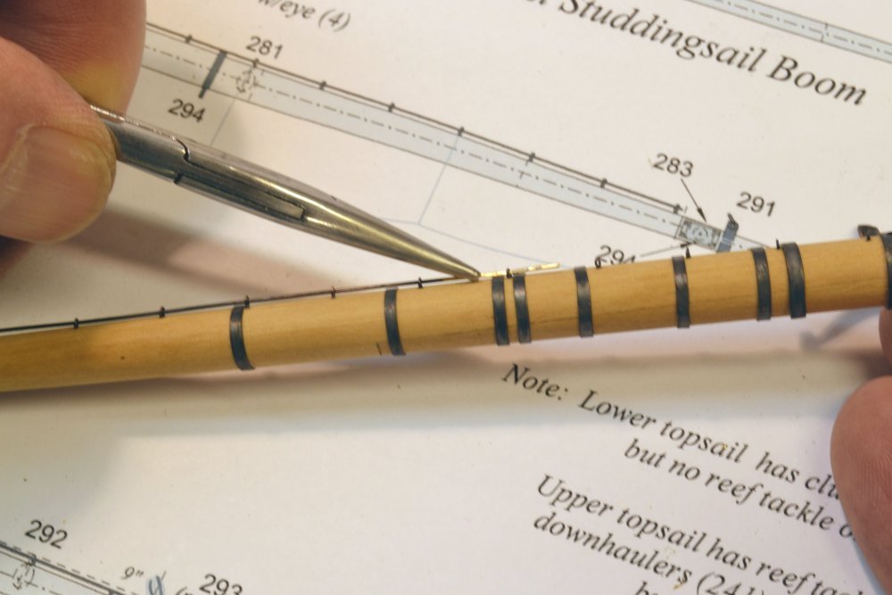
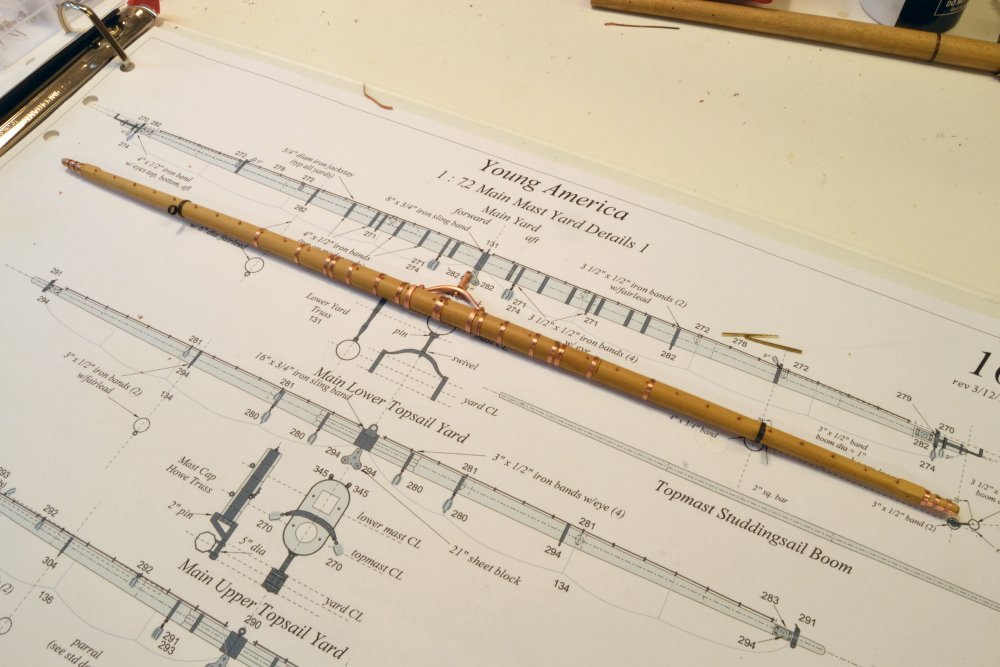
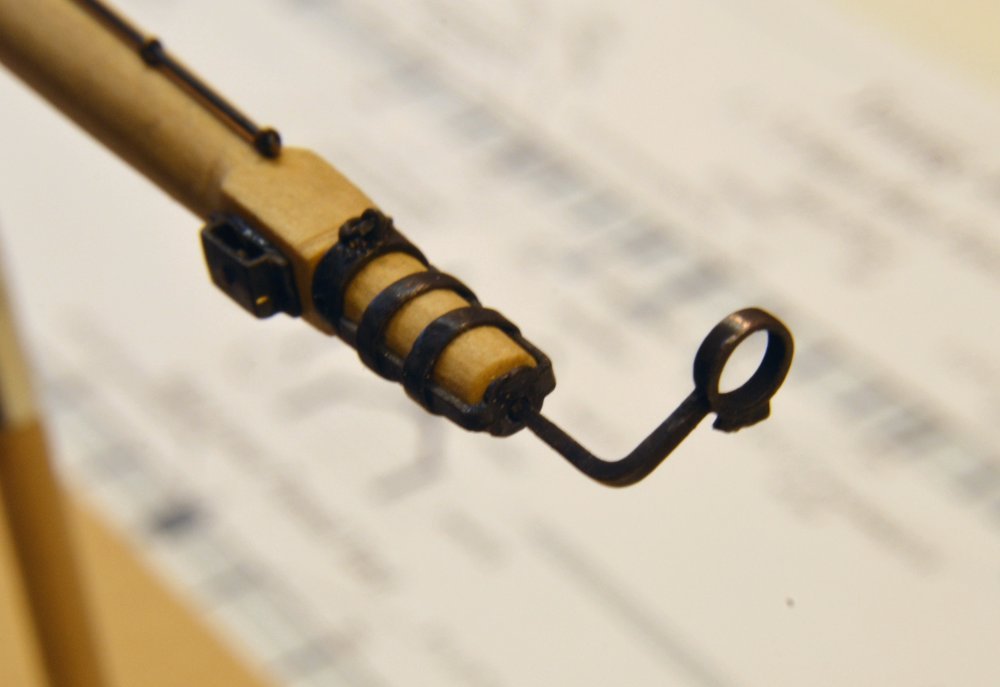
Young America - extreme clipper 1853 Part 279 – Main Yard Stuns'l Booms The main yard was fitted with the two topmast studdingsail booms. These supporedt the clews of the topmast studdingsails as well as the lower studdingsail yards that weresuspended from the ends of each when these sails were set. The booms were 42 feet long and 8 3/8" in diameter over their center sections. They taper to about 5 ¾" at the ends. All the drawing dimensions are expressed in full size decimals to permit easy conversion based on scale. The 1/72 converted sizes may be seen penciled on the drawing in the first picture. The picture shows a finished boom and the "first trim" of the second – a squared length of Castello marked with centerlines and the two points at the ends pf the straight section. The boom is grooved for jewel blocks at the outboard end and drilled for a lashing at the inboard end. The inner hole was also used to fix a temporary tackle for hauling out the boom. The next picture shows a finished boom set in the boom irons in the retracted position. The booms were shaped by the process described in earlier posts, then polished and finished with wipe-on polyurethane as described earlier. The next picture shows both booms lashed to jackstay stanchions at the inboard ends. The next picture shows a close-up of a lashing. I used untarred hemp for these and all lashings or fixings that would have been temporary. Because of the offset of the booms from the yard centerlines and the gradual taper of the yard, the booms are actually deflected somewhat to pull them fast to the stanchion. The last picture shows the end of the starboard boom after lashing on the two 9" jewel blocks. The upper block handled the sheet for the topmast studding sail, the lower block the halyard for the lower stuns'l yard. The outer iron is sized for the diameter of the boom's center section. Ed
- 3,618 replies
-
- 36
-
-
- young america
- clipper
- (and 1 more)
-
Paint is a lot easier to mask than stain. Ed
-
HMS Naiad 1797 by albert - FINISHED - 1/48
EdT replied to albert's topic in - Build logs for subjects built 1751 - 1800
Fantastic work, Alberto. Ed -
Thank you, Micheal. I can assure you that the drawings are as much work as the model - maybe more - and 2/3 of that is checking and review. Ed
- 3,618 replies
-
- 5
-
-
- young america
- clipper
- (and 1 more)
-
Thank you, Greg. The extra band on the starboard side of the yard was one of those little drawing glitches that have been corrected - or will be. Actually the finish is more of a benefit in removing handling smudges than for protection from the LOS solution - unless there is metal powder on an untreated wood surface. I had no problem using LOS next to untreated wood in all of the structural work on YA and Naiad. Keeping the wood clean of metal dust from hands or buffing is key. These spars take a lot of handling and its hard to keep hands clean during the concurrent metalwork - so the finish helps with that. Using the separate mandrel where possible for fitting and buffing helps with that. Ed
- 3,618 replies
-
- 8
-
-
- young america
- clipper
- (and 1 more)
-
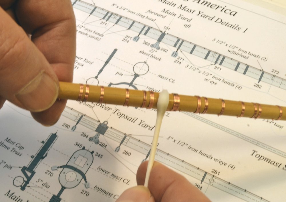
Young America - extreme clipper 1853 Part 278 – Completing the Main Yard The first picture shows the main yard temporarily connected to the mast. Most of the ironwork has been fitted. At his stage the yard was ready for the copper ironwork to be blackened. The brass-containing boom irons were pre-blackened before fitting. The next picture shows the removed yard and the ironwork being cleaned with isopropyl alcohol using a cotton swab. The wipe-on poly base coat resists the alcohol and allows any smudges to be removed and the copper to be degreased. The next picture shows the yard after the liver of sulfur blackening process. The blackening was done at the kitchen sink with tap water running. The yard and its fittings were liberally brushed with liver of sulfur solution and immediately rinsed under the tap. Any unblackened spots were re-brushed while wet and again rinsed. The yard was then allowed to dry. The next picture shows a closer view of the dried yard, taken the next day. The straight, black wire shown in the last two pictures, is the jackstay rod. This was next slipped through the stanchions as shown in the next picture. Straight .020" brass wire was used for this for its relative rigidity. It was pre-blackened using full strength Brass Black®. The eyebolts were spun from 28 gage copper wire. The fit is tight enough to keep the wire in place. In the last picture the jackstays have been inserted and clipped off. The outer boom irons have also been fitted and a finish coat of satin wipe-on polyurethane applied, using a foam swab shown in the picture. The finish was "wiped" using a dry foam swab. The finish was applied to wood and iron alike. Ed
- 3,618 replies
-
- 33
-
-
- young america
- clipper
- (and 1 more)
-
Flying Fish... sucuring studsail yards
EdT replied to paul ron's topic in Masting, rigging and sails
I believe that the spars you refer to are the studdingsail booms. The purpose of these was to support the clews, the lower ends, of the stuns'ls above and also to suspend the yard of the stuns'l below. These booms were housed just off the line of the yard by boom irons with circular straps somewhat larger than the maximum boom diameter. The inner boom irons could be opened to allow the inner end to be hauled upward to allow men on the yard to bend or reef sail. The stuns'l yards that were suspended from these were kept below, or sometimes in the tops, and mounted only when required with the sails pre-bent. In the retracted position the booms were usually lashed to one of the jackstay stanchions with some rope threaded through a hole in the inboard end. There was probably no one standard way to secure these, so tying them off in various ways would be acceptable. Bands on the boom irons were somewhat larger than the maximum diameter of the boom and sometimes fitted with a roller - usually on the outer iron that allowed the boom to slide out more easily. A temporary tackle was generally used to haul these out. Harold Underhill's Masting and Rigging of the Clipper Ship and Ocean Carrier is probably the best reference available on clipper ship rigging - out of print but can be found online. Ed -
That is some seriously beautiful metalwork, Frank. Very intricate, very precise. Painstaking work. What kind of solder did you use and what was used to blacken? It is true that wound stainless or Ni-Cr cable can have a mind of its own It is hard to stretch. Ed
-
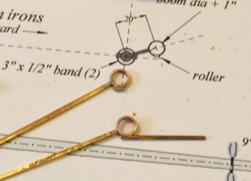
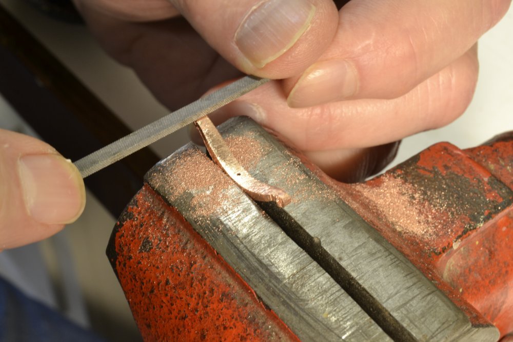
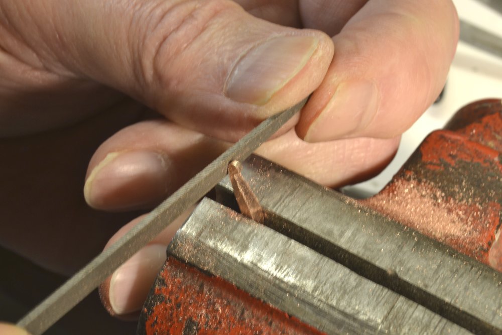
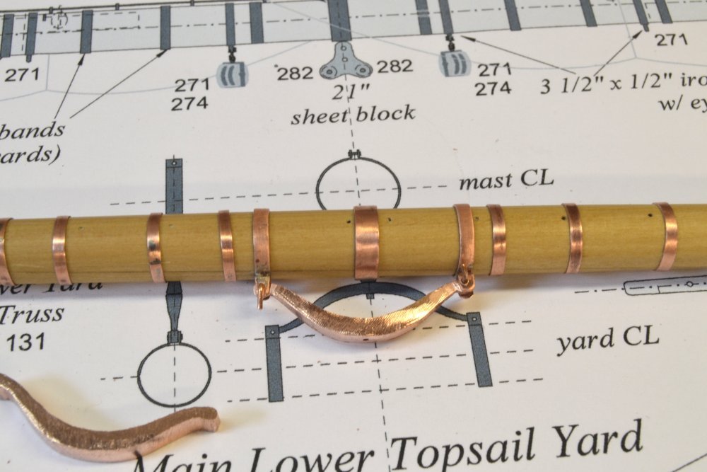
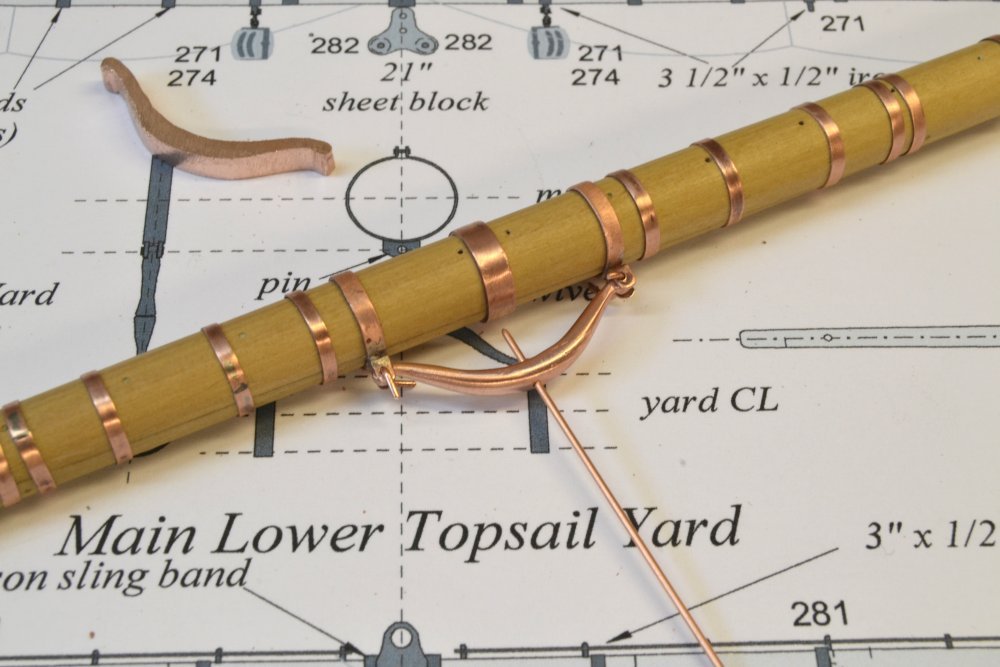
Young America - extreme clipper 1853 Part 277 – Main Yard Boom Irons The ironwork on the main yard continued with the fabrication and fitting of the boom irons, the supports for the topmast studdingsail booms. The first picture shows two steps in the fabrication of the inner boom irons. The large circular bands were first made to fit tightly in their positions on the yard. The smaller bands were sized to be about 1" larger in diameter that the 8 ½" diameter of the boom center sections. I used brass for the short arms between the rings – mainly because I had hard brass in that thickness. Making these of copper would have simplified the blackening process later. Because of the brass, these were blackened before installing on the yard, as will be seen below. The next picture shows a yardarm with its banding and pieces for the end cap and strap that support the outer iron. The straps were drilled first, then shaped as shown - in a vise with files, and then bent and clipped to the shape shown below. The straps are secured with tight-fitting, stretched rings pressed over the ends of the yard as shown in the next picture. The next picture shows the yard with the inner irons installed. Only the brass-containing inner irons are black. These were also fixed in place with a wire "bolt" – really a small wire nail in a drilled hole – riveted to hold the band on the underside of the yard. The last items to be made were the outer irons – sometimes called "Pacific irons". These consist of rings at the ends of bent iron bars. The picture below shows the rings – same size as the inner rings – soldered to lengths of brass bar stock. The rings were fitted with a roller on the underside to ease the movement of the boom. These were simulated by soldering a small bit of wire under each ring. The lower assembly shows the soldering configuration before clipping off the excess. A small round section was first filed out of the wire to help it fit to the band. Again, making these of copper would allow the yard to be completely assembled before blackening, which would then be done using liver of sulfur solution. The last picture shows the finished yard arm after blackening and installation of the outer iron. Final assembly of the yard and finishing will be described in the next part. Ed
- 3,618 replies
-
- 37
-
-
- young america
- clipper
- (and 1 more)
-
Hello, Christian. Probably the easiest way to simplify the model is to eliminate some of the rigging that is often left off models - items like reef tackle. bowlines, and others. I will think about how to suggest fewer lines. Other simpler methods may be used - for example, banding may be made with paper instead of the soldered copper. Shackles may be eliminated. Other simplifications may suggest themselves. I will give this issue some though to follow through on the simpler model idea that led to the 1:96 POB version being included. I will say that most of the rigging work is manually done - a lot of knotting and seizing. Once learned these tasks become more repetitive than difficult. Hope this helps. Ed
- 3,618 replies
-
- 8
-
-
- young america
- clipper
- (and 1 more)
-
Love the comments. First the number of hoops: At lengths of 82' and 86' respectively, I decided to make the fore and main yards as two-tree made spars. The main yard has a 30 ft scarph joinng the two trees, each about 60 ' long. These were bolted and banded, with heat-shrunk bands about 30" apart over the scarph length. Then there are bands for the sling, the truss, the inner boom irons and a number of eyebolt/fairlead bands. Youre right, Druxey - a lot of iron. Massive is right, Wefalck. The yokes are about 6 feet across and the distance between mast and yard centerlines is about 6 feet as well. These were both dimensions I estimated from typical data. With a center diameter of 23" and a length of 86', I estimate this yellow pine main yard to have weighed in at about 3 1/2 tons for just the wooden spar - no ironwork, stun'sl booms, sails or rigging Of course the weight of all this was mainly taken on the chain sling at the center - with some help from the topping lifts. Still smaller than a main yard on a first rate like Victory: 102' x 24" diam. Ed
- 3,618 replies
-
- 12
-
-
- young america
- clipper
- (and 1 more)
-
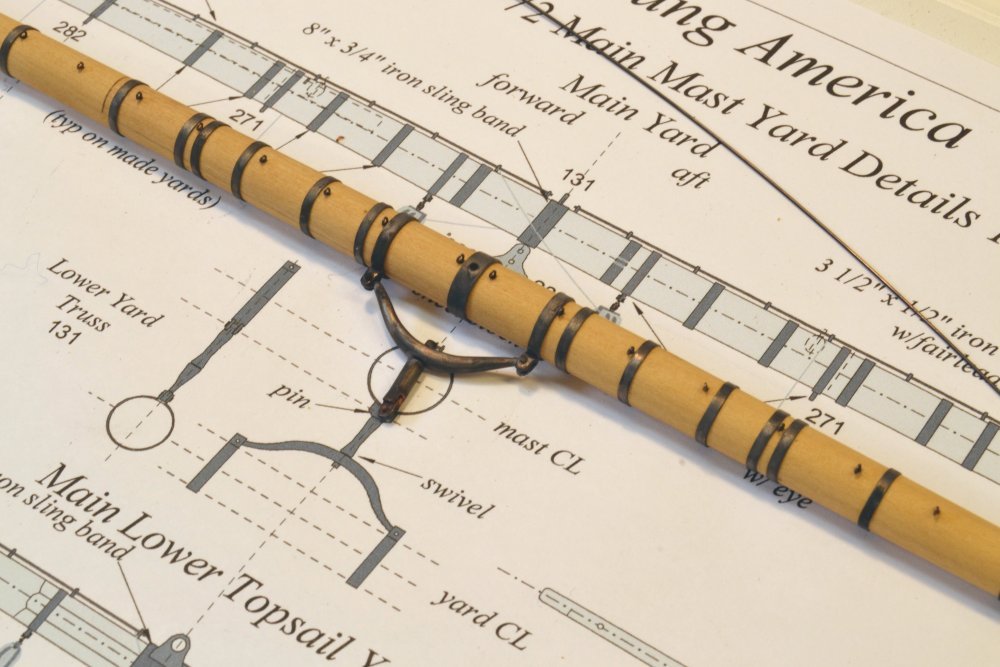
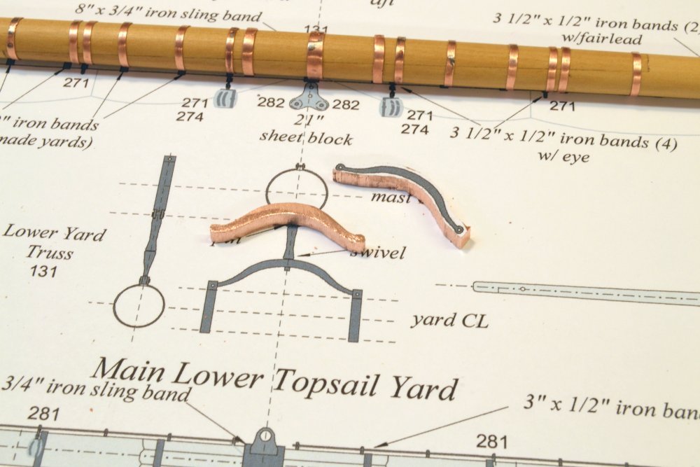
Young America - extreme clipper 1853 Part 276 – Main Yard Truss The main yard truss described here, and the mizzen version, are identical to the fore yard truss. The basic shapes shown in the first picture were cut out using a band saw with a 1/8" metal-cutting blade with a pasted-on pattern scrap as a guide. I cut both main and mizzen at this stage to avoid another band saw blade change later. I used the band saw to save time vs. the jewelers saw. The basic profile of the truss was then filed out as shown below in the next two pictures. The eyes at the ends were marked with dividers set from the band brackets on the yard, then drilled to accept 20 gauge copper wire. The unfinished yoke is shown in a test fit in the next picture. In the next picture the yoke has been rounded, polished, and again fitted to the yard band brackets. The center hole for the truss arm bolt is shown in this picture with a straight length of 20 gauge wire inserted. The next picture shows the fabricated truss arm. The arm was made using sections of telescoping tube. The eye that will fit into the mast band bracket was fitted into a slot at one end and silver-soldered. A short length of 20 gauge wire was soldered into the other end. In the next picture a flange has been soldered to the wire to hold the arm on the yoke, but allowing it to rotate. The assembly is set up, upside down, for bolting to the yard band brackets. Heads were first formed on one end of the copper bolts. They were then inserted from the top side o be clipped off just above the bracket surface and peened like the right-hand bolt in the picture. A square ended punch was tapped with a hammer in the position shown to enlarge the bolt head like a rivet. The left hand bolt is not yet clipped. The last picture shows the truss installed on the yard. This picture shows the top of the yard. All soldered band joints, though not very visible, were positioned out-of-sight under the yard. Ed


- 3,618 replies
-
- 45
-
-
- young america
- clipper
- (and 1 more)
-
HMCSS Victoria 1855 by BANYAN - 1:72
EdT replied to BANYAN's topic in - Build logs for subjects built 1851 - 1900
Continues to look great, Pat. You are right about those cameras. They are not very complimentary to our work - and the dust issue in close-up photos can be maddening. On the red paint bleeding: I will guess that your are not using acrylics. In my experience, once they dry they never bleed - even white over red. Solvent based paints on the other hand.... That 3D printed funnel is amazing. Ed- 1,013 replies
-
- 2
-
-
- gun dispatch vessel
- victoria
- (and 2 more)
-
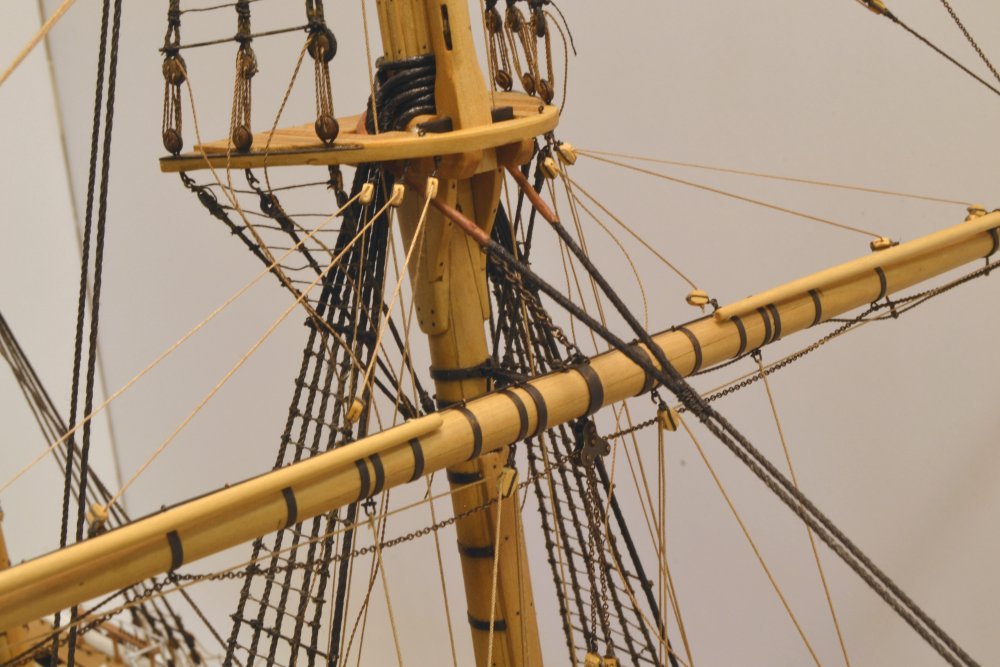
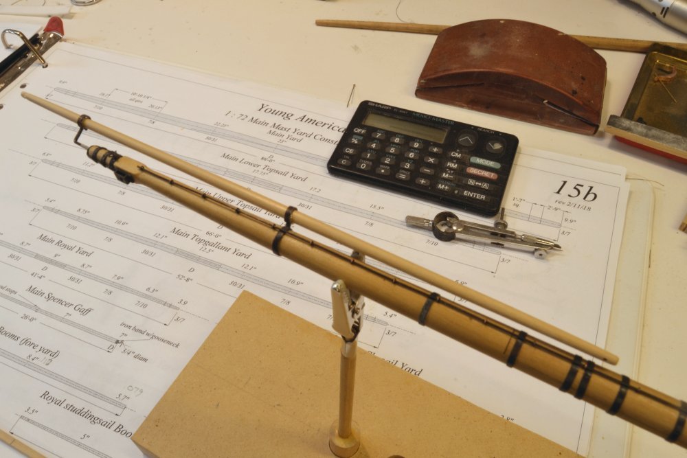
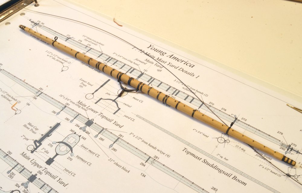
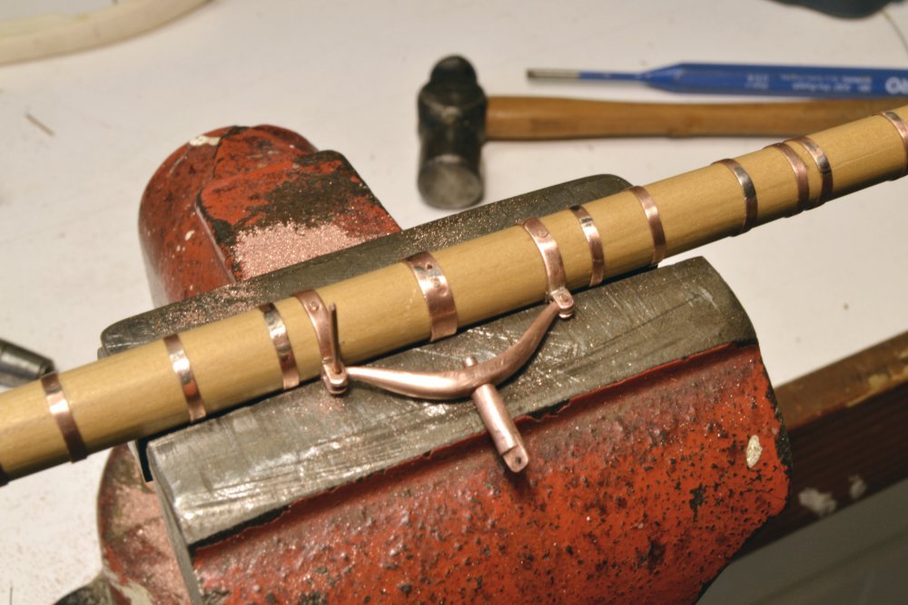
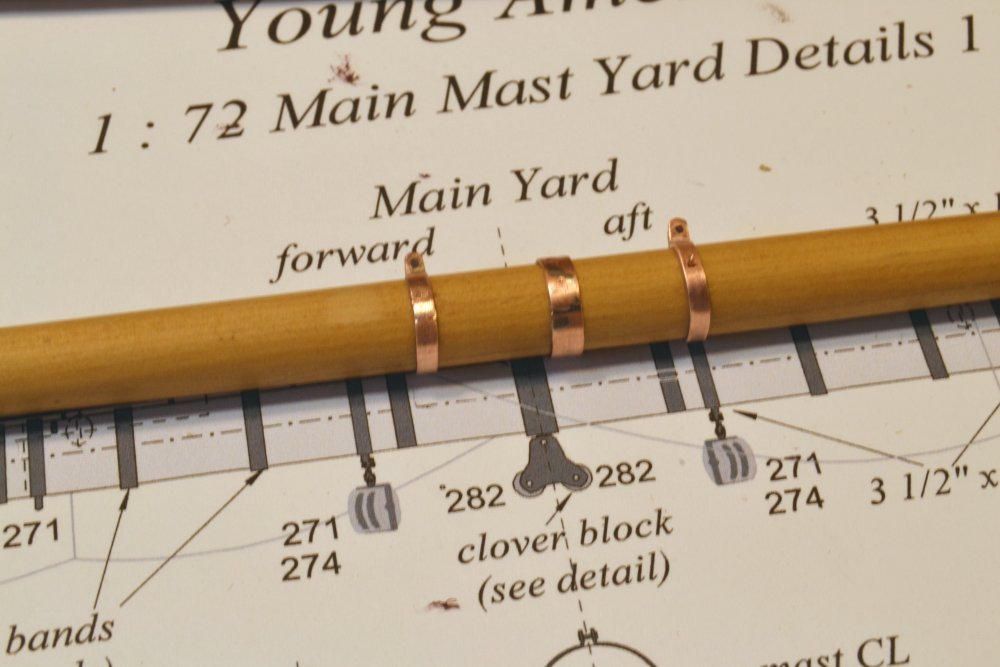
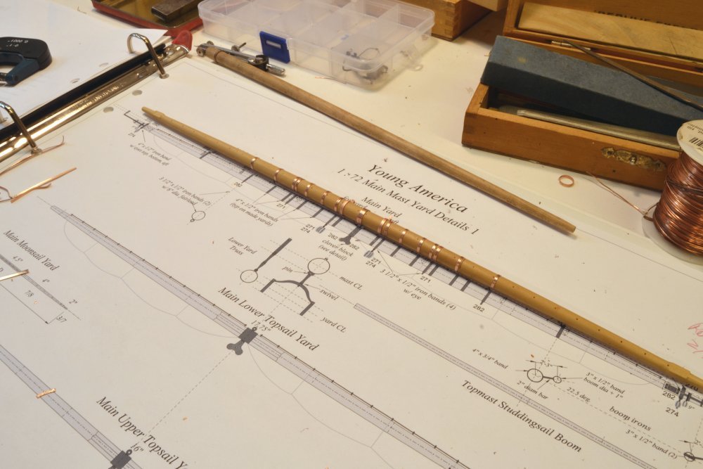
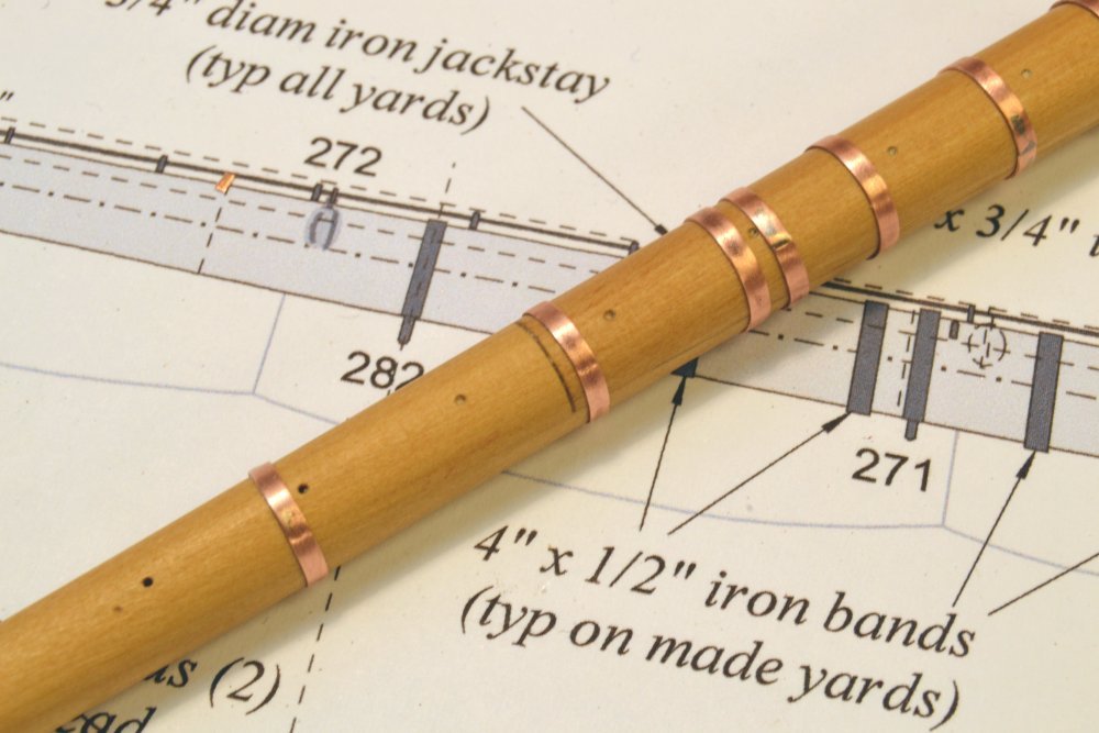
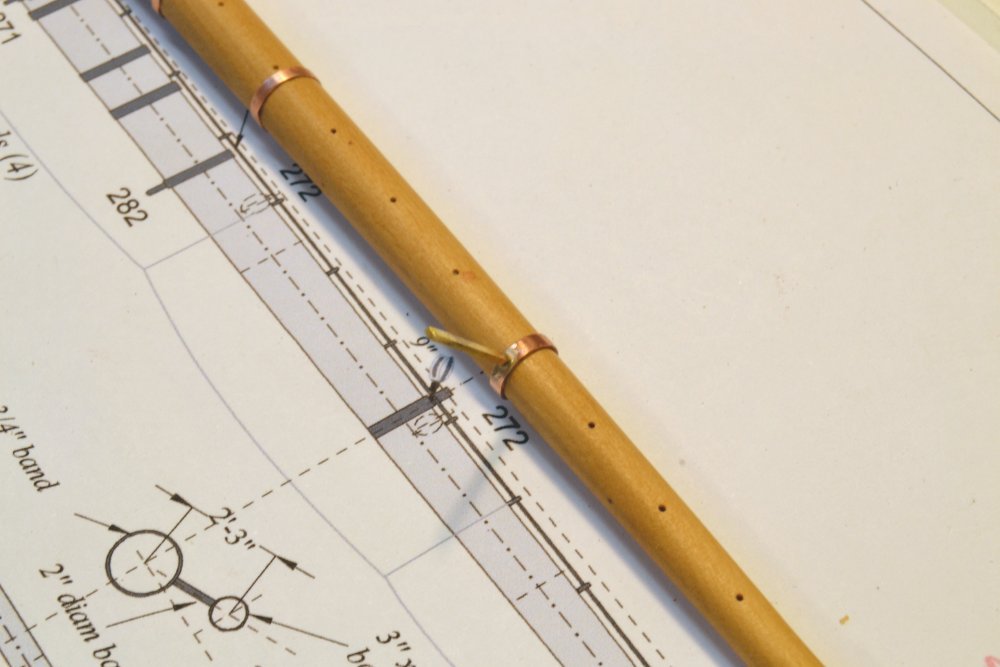
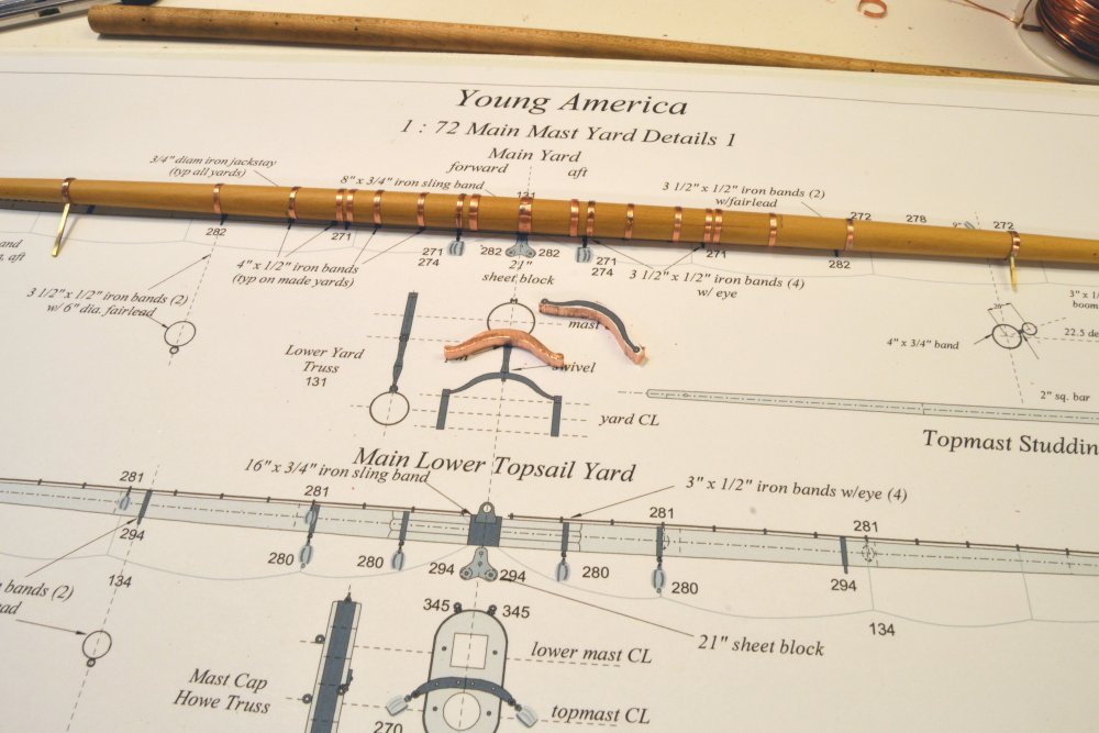
Young America - extreme clipper 1853 Part 275 – Main Yard The main yard was shaped as a two-piece "made spar" by the method used for the fore yard that was described in Parts 247 -248. After working through the first four foremast yards, the process used here for detailing is now the settled practice I expect to use on the remaining yards. After shaping and sanding, the yard was pre-finished with a coat of wipe-on polyurethane that was thoroughly wiped off. Then after complete drying it was buffed with a Scotchbrite® pad. This helps keep the yard clean by sealing the pores in the wood. The first picture shows the center sling band and the two truss bands installed. All the bands were made from copper strips, about 1/32" smaller than the circumference of the yard. The ends were then butted and silver soldered. These three and the boom iron bands shown below are .015" thick. The undersize bands were initially stretched on a tapered mandrel, then pressed to stretch into final position on the yard. This results in a tight fit that keeps the bands in place. The bands in the picture were also nailed on the underside with copper wire bolts for additional support, since they have a structural role. The two truss bands are fitted with brackets for the truss yoke. The next picture shows the yard with the central array of bands fitted. A few of these will be fitted with eyebolts, but most represent heat-shrunk hoops that hold the two spar sections together. The tapered maple mandrel mentioned above may be seen at the top of this picture. This is used to shape, file, polish and partially expand the bands after soldering. This avoids marring and smudging the yard. In the next picture an outermost reinforcing hoop is shown just inboard of the scarph joint end. All of these numerous reinforcing bands and eyebolt bands are .010" thick. They are positioned to avoid the equally spaced jackstay stanchion holes seen in the picture. The next picture shows one of the partially fabricated boom irons positioned on the yard. This will be removed for further fabrication work. The next picture shows all the bands out to the boom irons fitted. The picture shows roughed out truss yokes cut out from 1/8" copper plate. All three lower yard trusses are a standard size. Making this truss will be covered in the next part. Ed
- 3,618 replies
-
- 25
-
-
- young america
- clipper
- (and 1 more)
-
Mark, I would call it more like fumbling around rather than extensive testing.
- 3,618 replies
-
- 3
-
-
- young america
- clipper
- (and 1 more)