


EdT
-
Posts
2,214 -
Joined
-
Last visited
Content Type
Profiles
Forums
Gallery
Events
Everything posted by EdT
-
Bob, thank you for posting that great documentary, kept me out of the shop for an hour this am. Fantastic footage. Also, it was great to see Moshulu under sail. She is now tied up as a restaurant in Philadelphia. Mark, I finally settled on satin wipe-on poly for the spars after trying a number of other finishes starting with the wax that I use on the hull framing. I have not finished the decks yet because there are still things to be glued to it - mainly rope coils. The issue with the spars is keeping them clean with all the blackened metalwork and the handling that these require. I first ried shellac that also helped anchor the bands, then tried Tung oil then poly spar varnish, then the wipe-on polyurethane. I have used wipe-on poly a lot on furniture finishing. The first coat of poly on the spars is wiped very dry then polished with Scotchbrite. It seals the wood pores and can be cleaned better than the softer finishes before and/or after blackening if necessary using isopropanol. But with some care and clean hands that cleaning is unnecessary. Slow-drying oil and wax seem to attract dirt smudges and dust. I have also found that the best way to secure the copper bands is to stretch undersized bands into place, drilling and nailing those that support items like trusses or boom irons. I got to these methods by the time I reached to fore upper topsail yard and am now using it on the lower main yard that will be shown in the next post. I still favor the wax on the hull work for reasons explained in early posts and in the books. Ed
- 3,618 replies
-
- 3
-

-
- young america
- clipper
- (and 1 more)
-
Thank you, Rob. I have purchased chain from Cast Your Anchor as well as several others like Hobbyline, Model Expo, Cornwall Model Boats (Corel). I have seen nothing documented on iron protection. If I had to guess, I would say most probably grease, perhaps some tar or oil based concoction - I don't know. Our blackened, buffed metal is a modeling thing - like our finely honed joinery and polished woodwork. Ed
- 3,618 replies
-
- 3
-
-
- young america
- clipper
- (and 1 more)
-
Thank you all for the questions and comments – and for the likes, of course. My comments on the comments: Druxey, thanks. Yes, the amount of work to include all the rigging on one of these is a bit daunting, exceeded only, I have to say, by the effort to correctly document all of it – becoming a full time job – even for someone who thrives on complexity. BetaQDave, thank you. The short answer to your question is yes. I suggest paging back to Parts 269-271 to get some insight into the blackening used. Briefly, most is blackened after installation with Liver of Sulfur solution. This is one reason I used copper, although I believe this can be done with brass, but not with selenious salt solutions. Sliding blackened bands over the spars and handling after blackening leaves them more smudged. The method has also been discussed in a lot of earlier posts and, of course, in depth in the books. Greg, I do not know if railings on the tops were ever used on this class of ships, but there is no sign of them on the two Young America photos. This settled the issue for me. Also, I spend a lot of time paging through photos in books when questions like this arise and as yet have not seen these on other ships either. I guess a few topmen with one hand for themselves would be less at risk than a dozen or so marines loading and firing – don't know. CGN, thanks for the tip on chain. I have sources for 40 and 42 link chain plus a lot of larger sizes. I am generally using model chain somewhat larger than the actual sizes, which go down to 92 links/fathom (92/inch at 1:72). Anything under about 54 links will be modeled differently. I expect to use real chain from the topsails down – sheets and halyards. Hakan, thanks for the plug on the books. Ed
- 3,618 replies
-
- 4
-
-
- young america
- clipper
- (and 1 more)
-
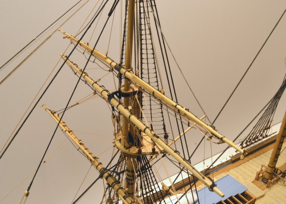
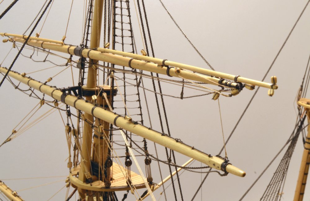
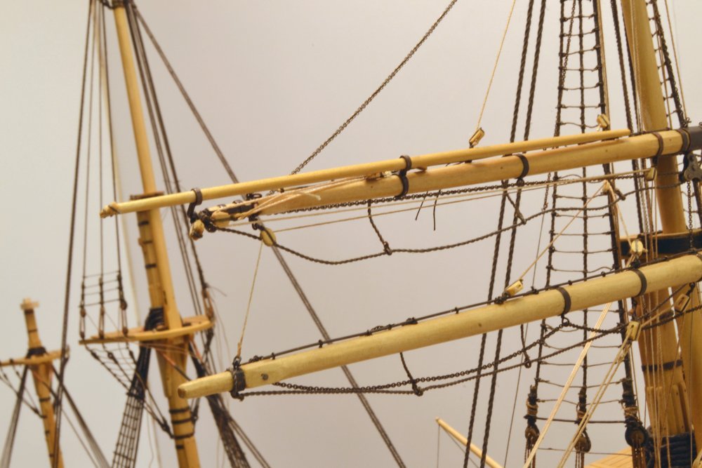
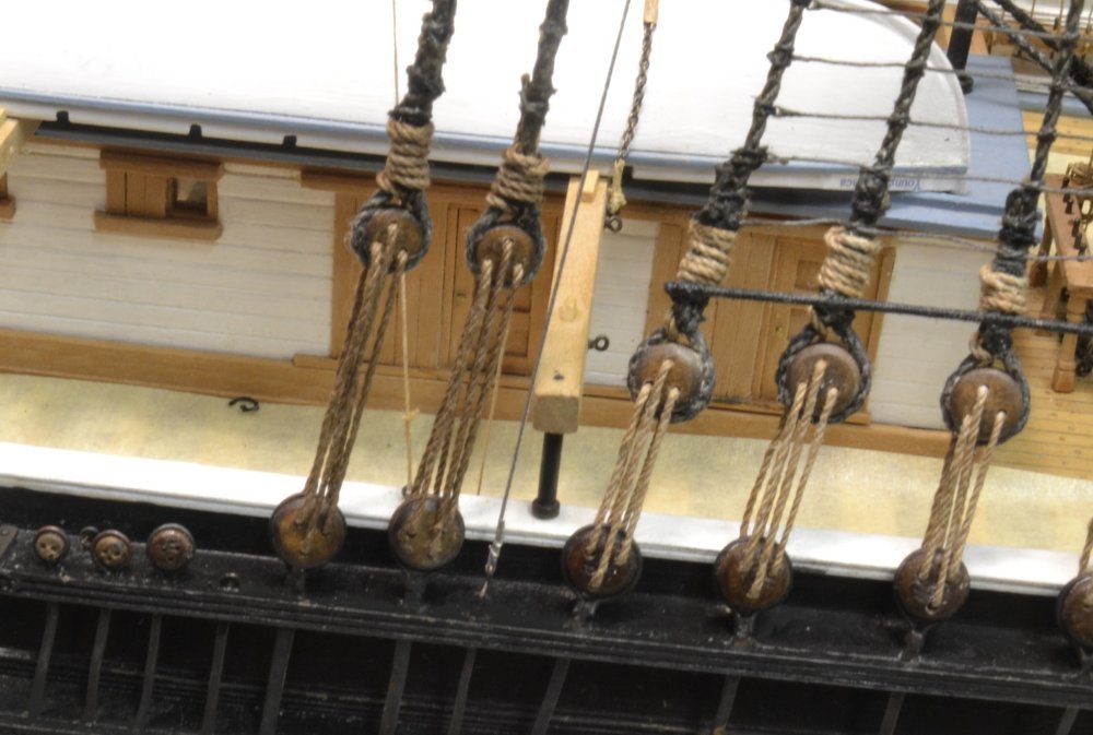
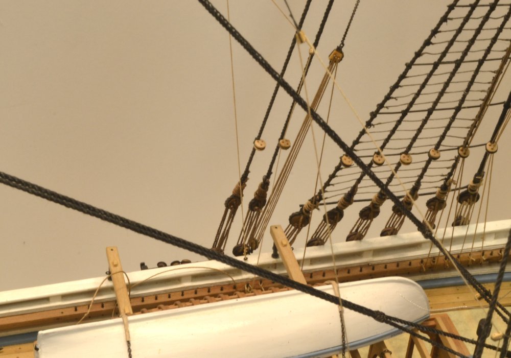
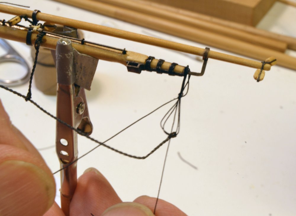
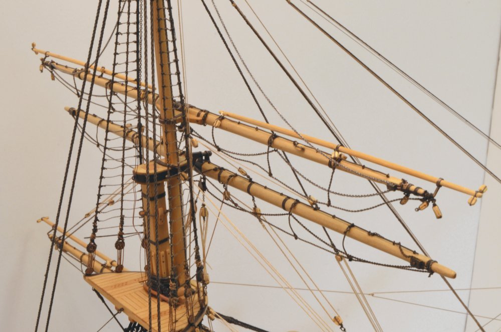
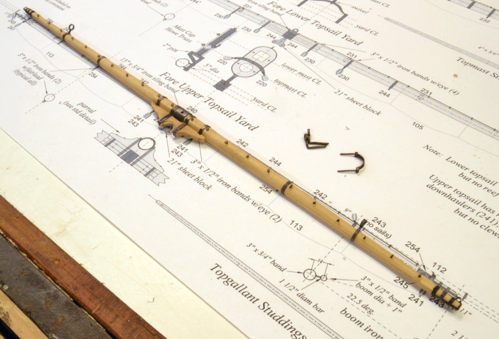
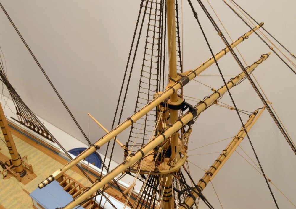
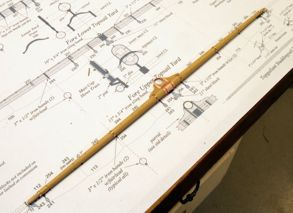
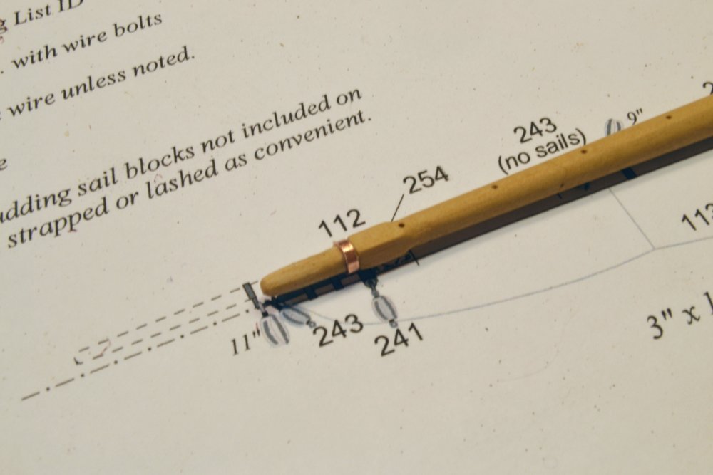
Young America - extreme clipper 1853 Part 274 – Fore Upper Topsail Yard Rigging 3 The last rigging lines to be installed on the upper topsail yard were the buntlines, the reef tackle and the downhaulers. The first picture shows the yard with these lines. The next picture shows these lines more clearly. As with the lower yard, the reef tackle block is tied off to the jackstay where it awaits the bending of the sail. Its standing end is seized to a single block suspended from the outer boom iron. The line then passes through the tied-off block, back through the first block, then through one sheave of the double block at the quarters and is belayed on the fife rail below. The double block is shared by the downhauler used to help lower the yard when gravity alone won't do the job – for example when the ship is heeled. The standing end of the downhauler may be seen spliced to a shackle on the lower tops'l yard arm band. Since it is never reefed, the lower topsail yard has no reef tackle. The buntlines are stopped at blocks lashed to the jackstay as with the other yards. They then pass through double blocks hooked eyebolts under the crosstrees as shown in the next picture. The tied-off topgallant sheet chains shown in this picture is a temporary measure until the topgallant yard is installed. The next picture shows the rigging on the starboard side. The large extra blocks dangling from the boom irons on this yard are the halyard blocks for the topmast studding sail yards that will not be installed. The next picture shows about one-third of the top's fairlead holes filled at this stage. All but two will be used. In the last picture the halyard gin block may be seen hauled up close to the mast sheave with the yard in its lowered position. The standing lifts that support the yard when lowered are shackled at their upper ends to the topgallant mast fid and will be added later after that mast is set. The work is now shifting to the main mast. Ed
- 3,618 replies
-
- 38
-
-
- young america
- clipper
- (and 1 more)
-
Thank you all for the comments and questions as well as the likes. Frank, I am glad that the rigging explanations are helpful. I am no expert, so I hope they are reasonably accurate. Pat/Sailor, there have been a number of comments in the past about scale. I do not think too much about it and do not try to do things at 1:72 that can be done at 1:48 for example. I tend to look at the model as a whole and say, what is right for this overall model? - rather than thinking of a certain standard for every part. The same question at a larger scale would yield different answers. stm, I would not anticipate any electrolytic action between copper or brass and stainless steel. These materials are close enough on the electrochemical scale to resist galvanic corrosion in even the harshest conditions. Here is a link that has a table and an explanation. I have never experienced this problem personally, but have never used stainless before. I plan to use some nickel-chromium and do not anticipate a problem with that either. https://en.wikipedia.org/wiki/Galvanic_corrosion No, John, Ed does not make chain. If you know someone who makes 42 links/inch chain, let me know. Cheers, everyone. Ed
- 3,618 replies
-
- 8
-
-
- young america
- clipper
- (and 1 more)
-
Young America - extreme clipper 1853 Part 273 – Fore Upper Topsail Yard Rigging 2 With all the bench work finished, the yard could now be hung to complete its rigging with a few exceptions mentioned earlier – mainly braces. This part deals with the halyard and the lower ends of the topgallant sheets. These are worked together. Tension in the halyard pulls the yard up. Sheets are used to hold the model yard down by linking them within the sheet block as described earlier. In the first picture the yard is suspended in its lowered position – its final position on the model. In this lowered position, the yard would be down on its lifts that will be rigged later. Unless there was some desire on the part of the captain to show off the masts with yards at the upper sailing heights, this is the most likely position after the sails were taken down. Note that the yard at this stage droops down a bit due to the clearance between the mast and the parral. In the next picture the yard has been raised to its upper position. The yard would be at this height under full sail. It would be lowered as reefs were taken in to shorten sail. The sails above would have been fully taken in before reefing this sail, so the yard could be lowered freely. I fixed the yard temporarily in this position so the gin block shackle could be fitted to the end of the halyard chain. The shackled block is shown in the next picture. In this picture the yard has been lowered. The copper shackle will be blackened. Note the drooping topgallant sheet chains. These will eventually be shackled to the topgallant clew lines when that yard is installed. The next picture shows the topgallant sheets at the sheet block. The chain sheets are connected to wire falls that run down toward the foot of the mast. The wire cable was made by twisting up 36 gauge stainless wire and is less than 1" in diameter – hard to see. I have highlighted the wire in white in the picture. This runs down to the block of a whip, which has a standing end hooked to a deck eyebolt and the fall belayed on the fore fife rail. When the sheet is put in tension to hold down the yard in this position, the chain interferes with the cap, as shown, if it is rigged through a fairlead in the top. This line would normally be slack with the yard in this position. I could leave it slack and rely on the downhaulers to hold the yard down, but slack model wire is pretty unruly and does not look good. I have tentatively rigged this line to run vertically down along the mast so that it runs in a straight line to the whip block in the lowered position. The two whip blocks with the cable connections may be seen near the center of the next picture. The wire cable is just visible in the picture after rerunning it as described above, roughly on the centerline of the mast. The standing end of the halyard is also wire, slightly larger, and may be seen at the lower part of the next picture. Without full tension, the wire shape shows the problem described above. Sufficient chain has to be left on this leg to raise the yard. The lower end of the wire standing leg, after tensioning, is shown seized to a channel eyebolt in the next picture. This wire is a bit more visible – still pretty slender. The running leg of the halyard is shown shackled to the upper block of a triple purchase tackle in the next picture. The lower block is hooked to a channel eyebolt on the port side. This halyard arrangement was used on large yards to distribute the weight forces to both sides of the hull. This tackle would consume a lot of rope when the yard was lowered. The downhaulers used to help lower that yard and the other yard rigging will be described in the next part. Ed
- 3,618 replies
-
- 32
-
-
- young america
- clipper
- (and 1 more)
-
Thank you both for the pics. Looks like a variety. The Gannet picture looks like what I had in mind in my response to Pat. All the solutions mentioned would be pretty inconspicuous at 1:72.. Ed
- 3,618 replies
-
- 2
-
-
- young america
- clipper
- (and 1 more)
-
HMS ROYAL KATHERINE 1664 by Doris - 1/55 - CARD
EdT replied to DORIS's topic in - Build logs for subjects built 1501 - 1750
Doris, your artistry with card knocks me out. No words. Ed- 1,035 replies
-
- 9
-
-
- royal katherine
- ship of the line
- (and 1 more)
-
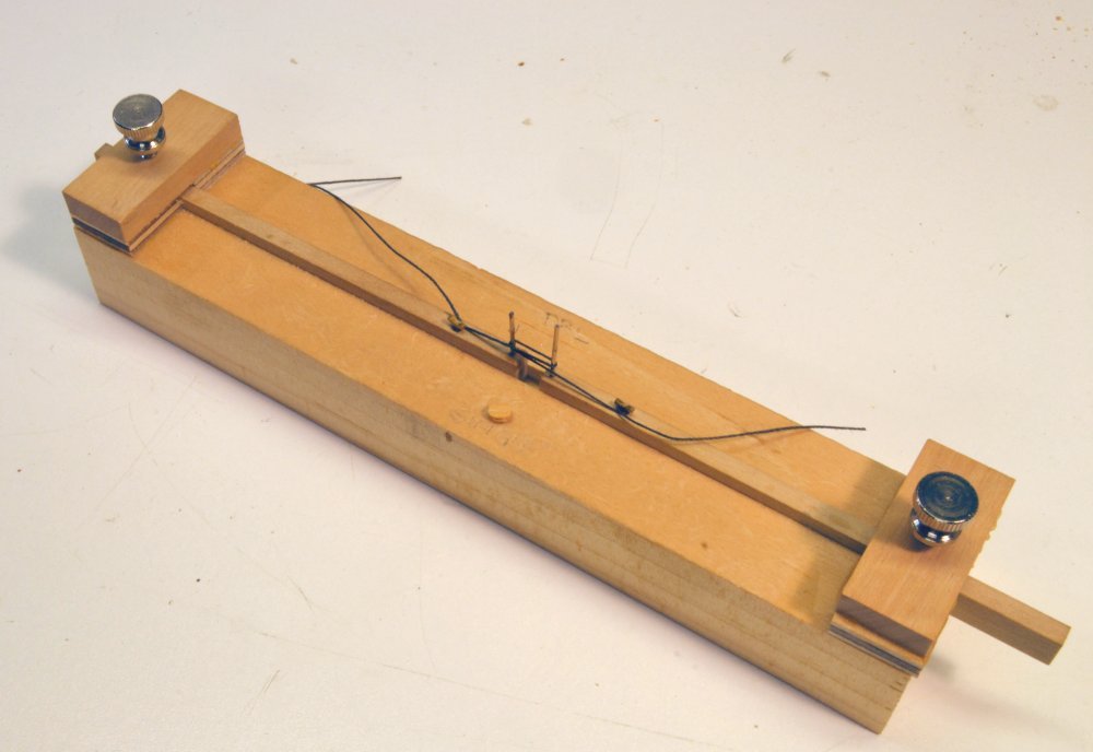
Thanks, everyone. The tool for strapping blocks is helpful on larger blocks, say over 1/8" to 3/16". Many on the model are small at the 1:72 scale so it is easier to simply tie these around a pin. The tied black faux seizings are hard to distinguish and are much easier to make. Larger blocks and double blocks may be seized using the fixture, but the thread ends need to be cut off short. I have been setting the distance between pins by eye, but if there were very many to do this way I would want to add either some marks for different blocks sizes or use wooden gauge strips based on size. Mark, I have not seen details of how jackstays were held in place. Perhaps the 3/4" rods were bolted or riveted at the ends or to one of the stanchions. On the model they are a close enogh fit in the eyebots that they stay in place. I tacked the first ones with CA, but that does not seem necessary. The brass rods are blackened, passed through the full yard, then clipped in the center and at the ends. the brass wire is in straight lengths. I am glad to hear the shackles are working for you, Pat. I could see expanding the use of this type to reduce the need to solder so many. Ed
- 3,618 replies
-
- 5
-
-
- young america
- clipper
- (and 1 more)
-
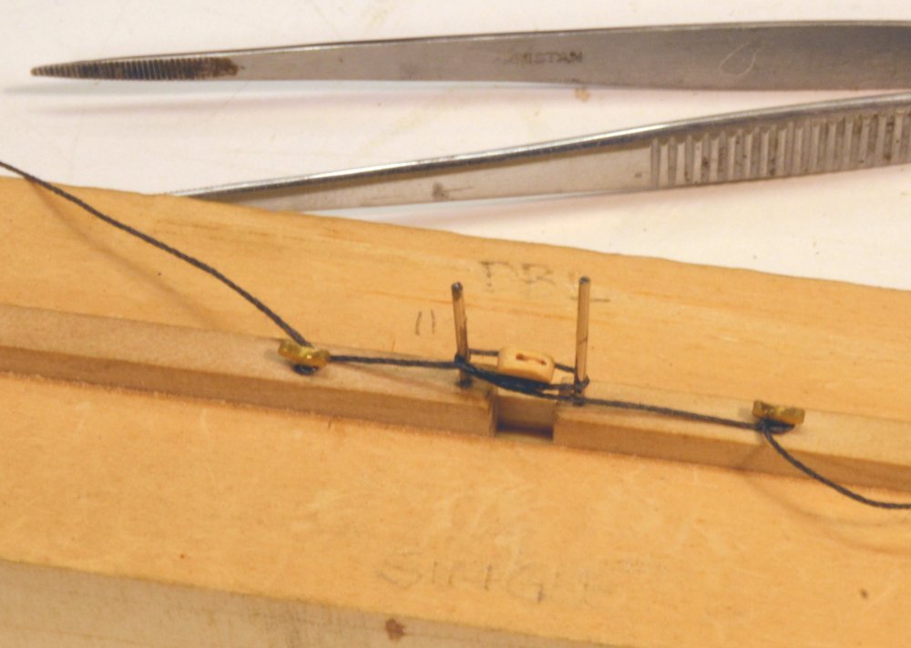
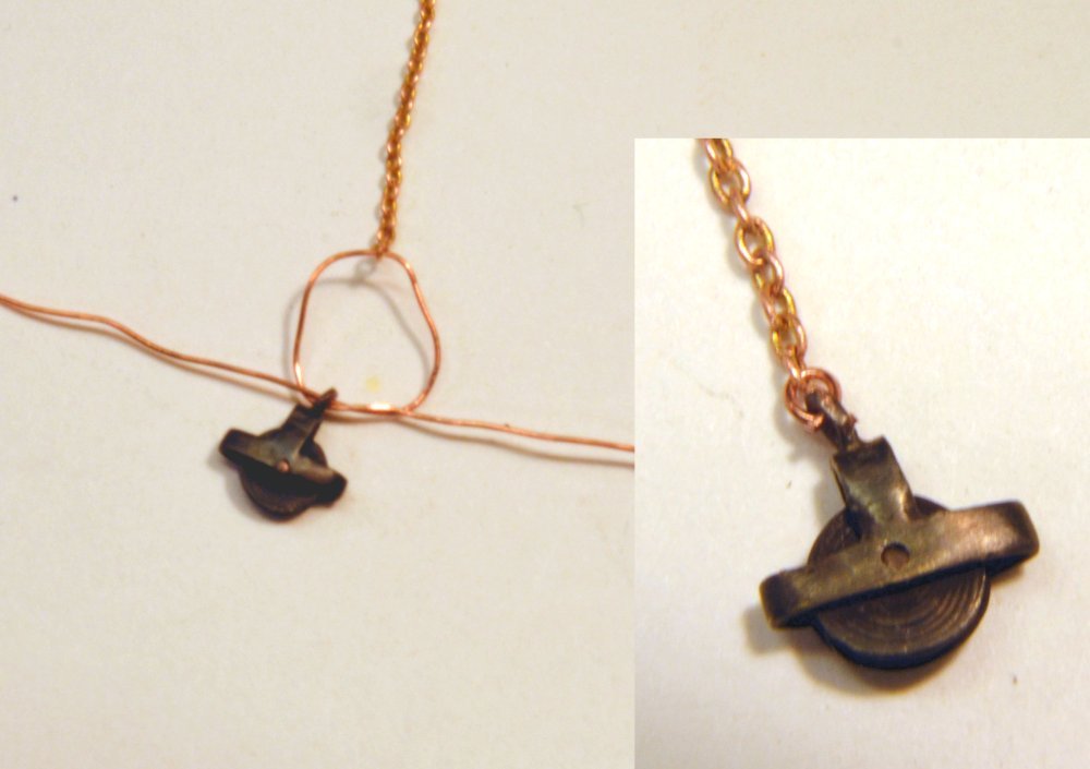
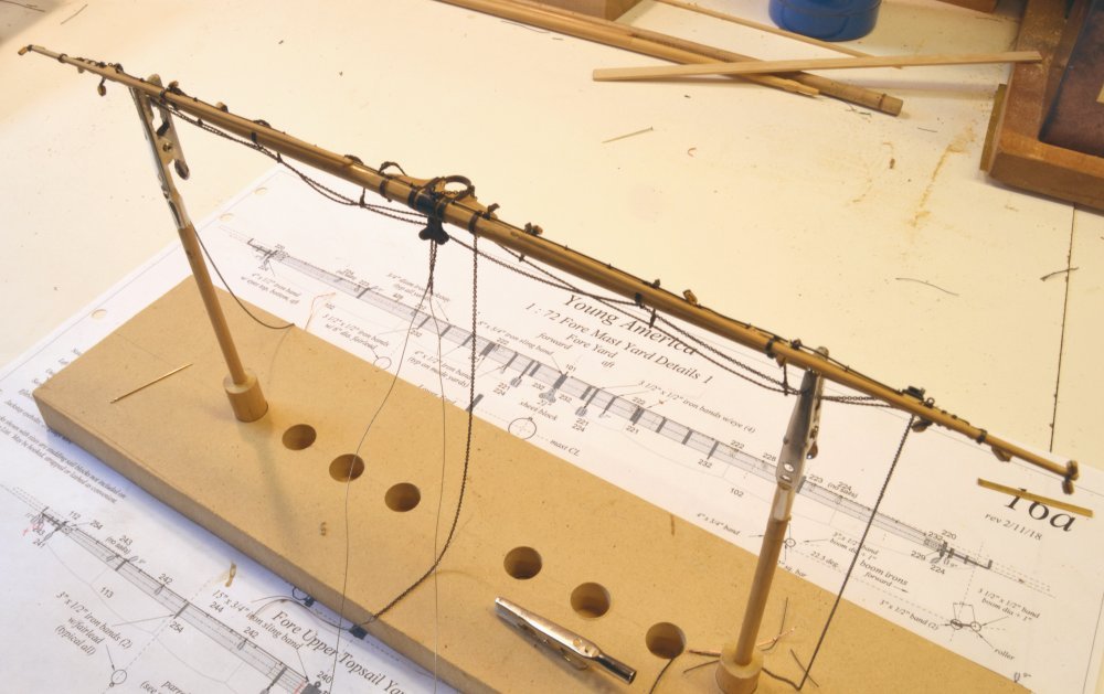
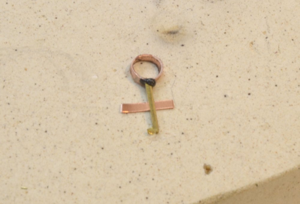
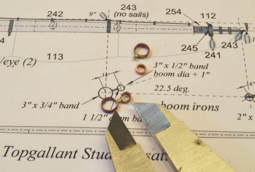
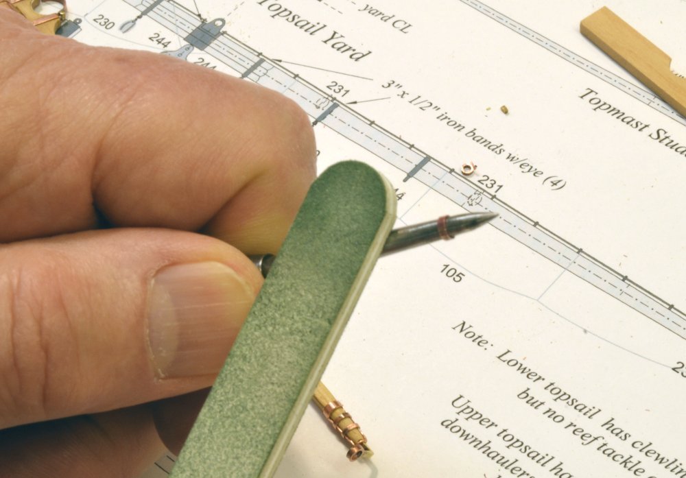
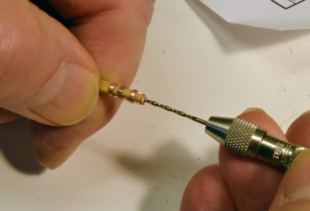
Young America - extreme clipper 1853 Part 272 – Fore Upper Topsail Yard Rigging 1 The last picture in Part 271 picture showed the yard set up for rigging, but first the topgallant sheet blocks had to be fitted to the yard. The first picture shows a trial fit with one of these before both were blackened. This picture also shows the studding sail boom irons on this end of the yard and the two jewel blocks at the end of the boom. Studding sail blocks that would likely have been "permanently" rigged will be shown on the model, but other studding sail rigging will not be modeled. In the next picture the yard has been returned to the fixture and rigging of the footropes has begun. The stirrup eyes and the ends of the footropes are secured with lashings – to jackstay stanchions in the case of stirrups and the inner ends of the footropes, and to the outer boom irons in the case of the footrope outer ends. The next picture shows a lashing being tied. Guterman® quilting cotton is being used for all small lashings – black for permanent connections and ecru for temporary – like reef tackle blocks and inner boom lashings. To make this type of lashing, I have been double looping the line through the eye and around the boom iron (or stanchion, etc.) A clove hitch is then made around the turns as shown. Before this is tightened the other end is pulled to shorten the lashing to its final length. The hitch is then tightened and the lashing touch with diluted glue. There are several blocks lashed to the yard for buntlines, reef tackle, downhauls, etc. On this yard most are 9" (1/8") single blocks, strapped with a single thimble. For these small blocks I usually form an eye around a pin, tie it with a double hitch to simulate the seizings, then tie an overhand knot under the block to simulate the strap splice. Some of these may be seen lying about in the second picture. For blocks with thimbles at each end, this method is not practical. So something more like the actual strapping is made. A strap loop is first made as shown in the next picture. The rope is wrapped around two pins set at a distance that will allow the two eyes to be seized. The strap splice is made by passing the rope through itself then gluing. When the glue dries the block is inserted as shown in the next picture. The excess strap rope is cut off and a seizing tied to form the eye at each end of the block. This method was used for the reef tackle blocks lashed to the outer boom irons. The next picture shows the method used to simulate a shackle between the halyard tie and the iron gin block with the finished shackle shown in the inset. The picture shows a test of the method. The actual connection will need to be made on the model after the tye chain is attached to the yard band and threaded through the mast sheave. To make this shackle, wire is passed through the chain link then through the eye on the block from both directions with an overhand knot set within the block eye. The ends are then pulled tight and clipped off as shown in the inset. The final configuration of the halyard will be shown in the next part. The next picture shows the bench work finished and the yard ready to be hung. The topgallant sheet chains may be seen hanging from the center sheet block and from the cheek blocks at the ends. Securing the two chains inside so the yard may be pulled down by the sheet tackles was discussed in an earlier post. The picture also shows the chain halyard tye suspended from the sling band. All the chain ends are threaded with wire to assist in getting then through the various sheaves. Pushing on a rope has its difficulties but pushing on chain is impossible. In the last picture the yard has been hung and is ready for the next steps – securing the sheets and halyard. Ed
- 3,618 replies
-
- 38
-
-
- young america
- clipper
- (and 1 more)
-
ancre Chebece 1750 by Jeronimo - FINISHED
EdT replied to Jeronimo's topic in - Build logs for subjects built 1501 - 1750
Wow. Fantastic work - as usual, Karl. Ed -
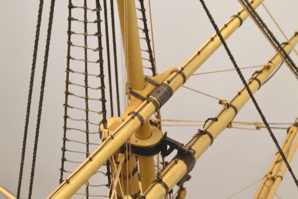
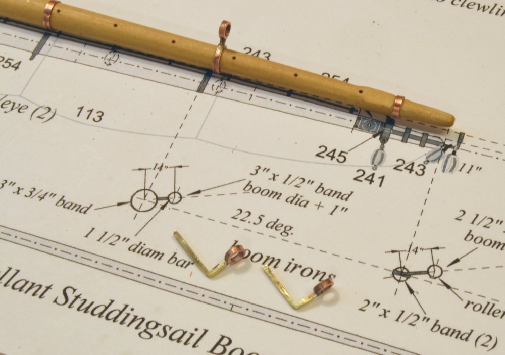
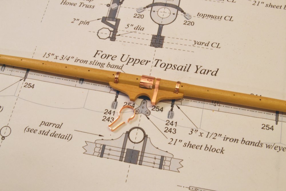
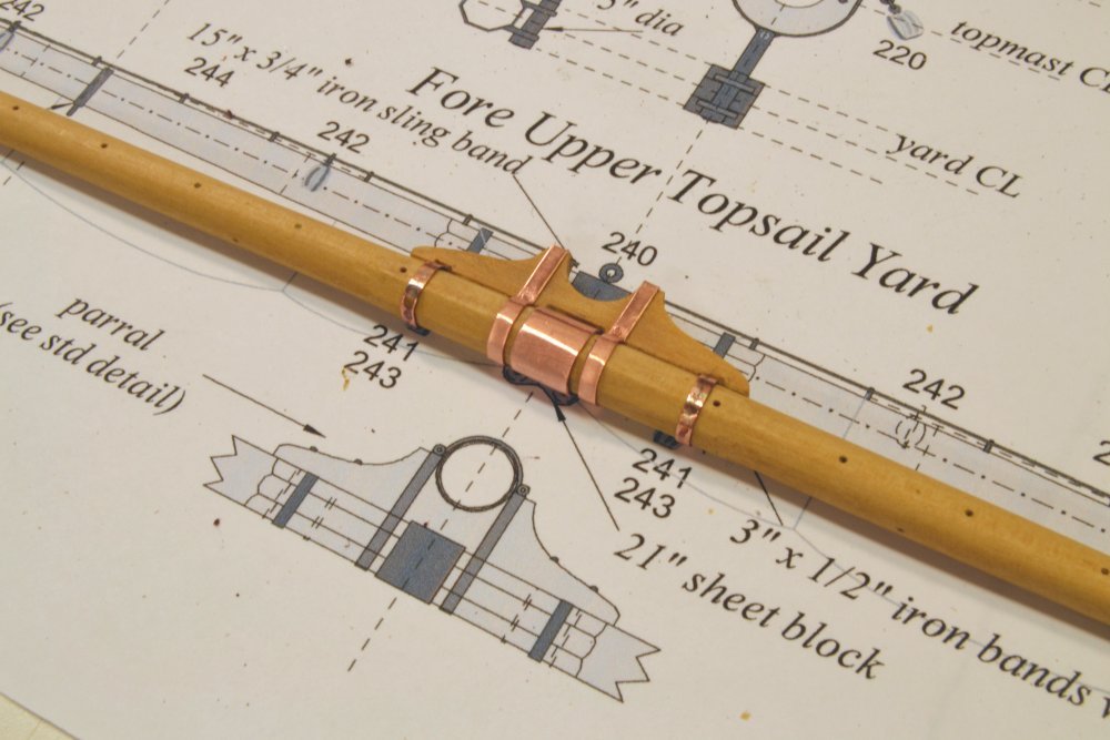
Young America - extreme clipper 1853 Part 271 – Fore Upper Topsail Yard Ironwork 2 The first picture shows all the ironwork fitted to the yard except for the pieces containing brass that were blackened before assembly. All band eyebolt holes have also been drilled. At this stage the yard and its metalwork were cleaned using isopropanol and cotton swabs. The next picture shows a closer view. The 28 gauge jackstay eyebolts are pushed into their holes, which seems to be sufficient to keep the jackstays in place. The next picture shows the yard with its copper ironwork blackened. To blacken the copper parts, the entire assembly was brushed with liver of sulfur solution starting at one end. As the copper turned black, the yard was held under running water to wash off excess blackening solution. The yard was then left to dry overnight. The next picture shows the yard temporarily fitted to the mast. After drying, the yard was finished with satin wipe-on polyurethane using foam swabs to apply and wipe the finish. After trying other finishes I am starting to settle in on this method. The foam swabs are free of lint. The jackstays are brass and were blackened with full strength Brass Black® before sliding them through the eyebolts. Except for the wooden parral, no glue has been used on this yard. The center of the yard is shown in the next picture. The parral band pins are only temporarily inserted. Note that there is a slight gap between the parral lining and the mast, allowing the yard to slide up and down easily. In the last picture the yard has been removed and set up for rigging work. The long, slender topmast studding sail booms have been fitted and tied off at their inner ends. The yard is ready to be mounted for rigging. Ed
- 3,618 replies
-
- 40
-
-
- young america
- clipper
- (and 1 more)
-
Here is another link for smaller spools. You want solid bare copper. https://www.amazon.com/Mandala-Crafts-Beading-Wrapping-Jewelry/dp/B00YDEZAAO/ref=pd_sbs_201_5?_encoding=UTF8&pd_rd_i=B00YDEZAAO&pd_rd_r=GN21WV3R8EJD5Z4ZPXP4&pd_rd_w=1hKTE&pd_rd_wg=4fvLo&psc=1&refRID=GN21WV3R8EJD5Z4ZPXP4
- 3,618 replies
-
- 3
-
-
- young america
- clipper
- (and 1 more)
-
Thank you, Doris. Knowing and admiring the quality of your work, this is much appreciated. Ed
- 3,618 replies
-
- 4
-
-
- young america
- clipper
- (and 1 more)
-
Here is a link, Maury. You can find smaller spools. A lot of artistic wire is coated. You do not want that. If is is magnetic it must be copper coated steel? https://www.amazon.com/Bare-Copper-Bright-Diameter-Length/dp/B000IJU1ZW/ref=pd_ys_c_rfy_rp_all_1?_encoding=UTF8&pd_rd_i=B000IJU1ZW&pd_rd_r=GKKJMHVS3KZ7SHEPMZ9Y&pd_rd_w=GV3pT&pd_rd_wg=uhINb&psc=1&refRID=4AFD9YGQTP100F9AHBEV
- 3,618 replies
-
- 2
-
-
- young america
- clipper
- (and 1 more)
-
Thank you all for the comments and likes. Yes, Druxey, there is a lot of ironwork on these lower yards, but it will become less as we ascend. Pat, copper does have some distinct advantages and some disadvantages. On the plus side: the ability to blacken parts after mounting on wood, its ductility that permits forming, stretching of wire for reducing diameter and hardening, the ability to expand rings to an accurate fit, and availability of copper wire in a wide range of sizes. On the negative side, it is soft and difficult to machine compared to brass. Brass machines well and is less prone to bending. Ed
- 3,618 replies
-
- 6
-
-
- young america
- clipper
- (and 1 more)
-
HMS Victory by EdT - FINISHED - 1:96 - POB
EdT replied to EdT's topic in - Build logs for subjects built 1751 - 1800
Thank you, Paul. It does indeed seem like a long time ago. Ed -
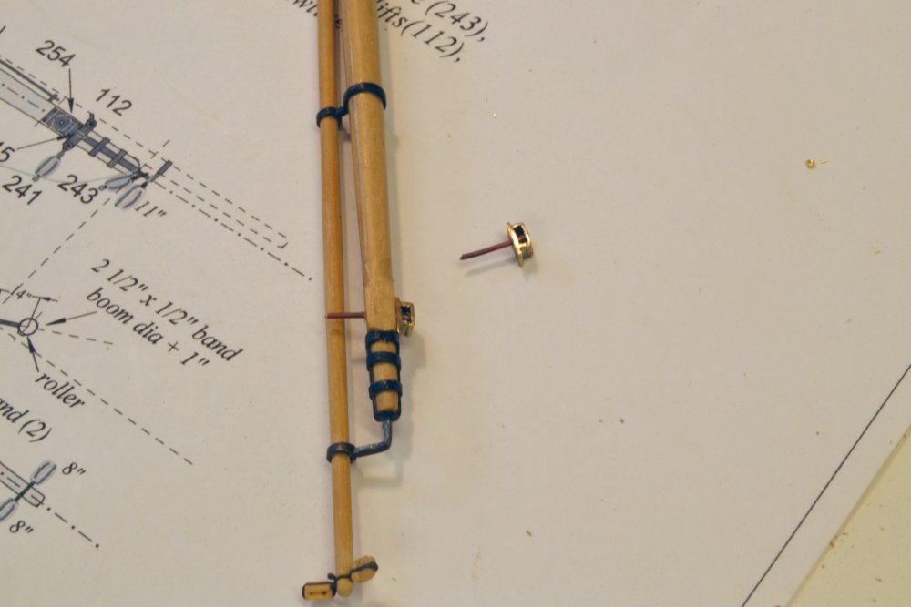
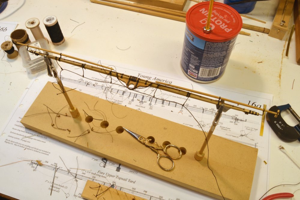
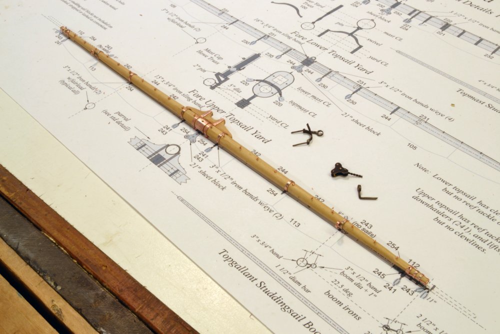
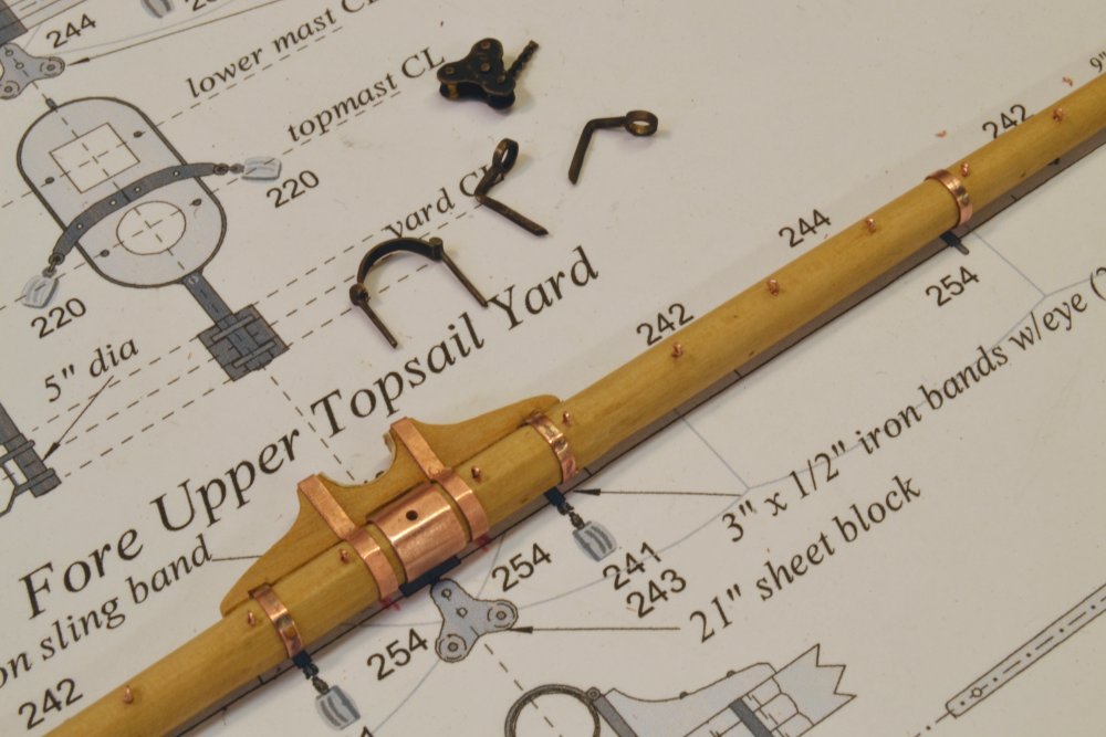
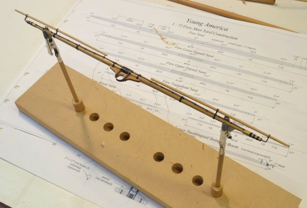
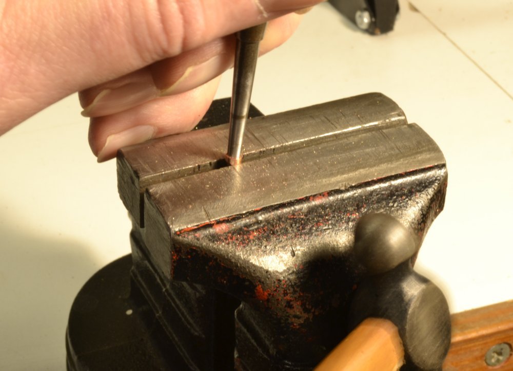
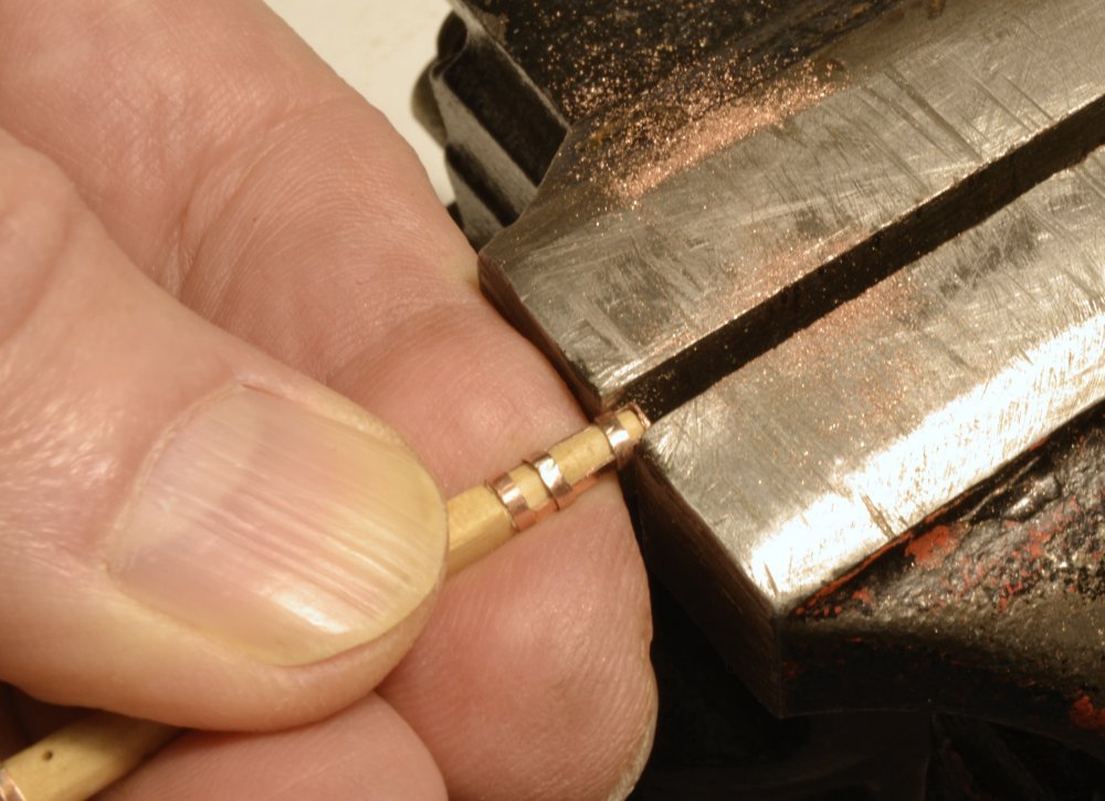
Young America - extreme clipper 1853 Part 270 – Fore Upper Topsail Yard Ironwork 1 To avoid excessive repetition and to avoid tedium in these posts, I will not be describing all 18 of Young America's square yards at this same level of detail, so do not despair. However, the first three are each different in the way they are supported and rigged. Some of the fittings are therefore unique and it has been interesting to design and make them. Even so, some of the work shown in this post has been described before. The first picture shows the fore upper topsail yard with its parral and all of the bands fitted except for those that support the boom irons. All but the yardarm bands at the ends were made by cutting and silver-soldering .010" thick copper strips that were slightly undersized so they would be stretched to a tight fit when positioned on the yard. After soldering, the bands were shaped, filed, and polished on a separate tapered mandrel to avoid damaging or smudging the yard. I believe all this was described in earlier posts. The bands at the yardarms were made thicker using copper tube. These stronger bands will be drilled for multiple eyebolts – at least three each. Slices of tube were expanded to fit the yardarm as shown in the next picture. A hardened scribe is being used to expand the band by tapping with a hammer with the band resting on the edges of the vise jaws. The band was then pressed into position on to the yardarm as shown below. This band will be drilled for three eyebolts – one for the standing lift, one for the brace, and one for the downhauler used on these doubled yards. Most bands have at least one eyebolt fitted. These were all drilled later. Supports for the studding sail booms are the most complex pieces to make. These include a boom iron on the yard and another at the end of the yard. This latter support requires ironwork to reinforce the yardarm for this loading. The next picture shows one of the boom irons set up for soldering. The band for the boom was made from tube as described above. The square arm was made from brass for stiffness. The copper strip under the arm was used to center the arm on the band. The next picture shows the next assembly step. The length of the square section needs to be cut fairly accurately. One soldered assembly is being checked in the picture. The yard bands were made from somewhat thicker strips (.015") for strength. The next picture shows one of these assemblies fitted and the pair of fabricated outer irons for this yard. The outer irons are supported by a strap bored at the end for the outer iron. This strap is secured to the yardarm by two tightly fitted bands. These were of the soldered type. In the next picture, one of these is being polished on the tapered scriber. The vise was again used to force the bands over the longitudinal strap as shown in the next picture. The support straps were predrilled to fit the boom irons, but to avoid possible damage, the yardarms were hand drilled with a much smaller drill, then bored out to full depth by hand after the ironwork was fitted. This is being done with a pin vise in the next picture This complex metalwork at the arms was given some additional shaping and smoothing. It was then very lightly polished using a new, clean buffing wheel. To be continued. Ed
- 3,618 replies
-
- 37
-
-
- young america
- clipper
- (and 1 more)
-
I am really playing catch-up here, Maury. the model looks great -really shaping up. I like thehooked iron-strapped blocks and really love the anchors. I almost thought someone had nicked my serving machine but its till there. Yours looks great. Ed
- 525 replies
-
- 3
-
-
- anchor hoy
- hoy
- (and 1 more)
-
I agree with Druxey on this. If you plank the wales first, you will need to later butt the counter planking neatly against it - and also, of course, leave excess wale planking that will later be cut off flush with the counter. Fitting the curved counter planks to fit nicely with the curved inside of the wale is work - much easier to install the counter, file off the ends flush with the outside of the outer counter timbers, overlap that with the wale planks, then file those off flush with the counter. Looking great, Mark. Ed
-
N, Drawing 4 is the Centerline Structure Drawing which was furnished as a full sized printed drawing. It is not on the CD. You should have received this in the packet of printed drawings that came with the book. If you did not receive this drawing in the plans packet, you should contact SeaWatchBooks. Ed
-
Dz, I have had a lot of success blackening copper parts on wood without staining the wood using liver of sulfur solution. I use copper for that reason. I have also had success blackening brass on wood using a product called WinOx, but have not used that very much. I have described this method in many posts on this and the Naiad build logs on MSW - and in more detail in the Naiad and Young America books. This does not work using the blue selenious salt agents. The liver of sulfur solution neutralizes quickly so does not leave reactive products on the wood. The wood must be clean and free of metal dust or that dust will blacken and leave smudges on the wood surface. This can be difficult on items like spars where there are a lot of parts and a lot of handling when fitting bands and other pieces. In this case I try very hard to keep the wood clean, prefinish it to seal the surface before adding metal parts. I then brush the liver of sulfur solution on the entire yard and put the black areas under running water immediately as they blacken. When completely dry I finish the yard assemblies to seal the black metal. You may see the results on the yards in the pictures that were all done this way. I am currently using wipe on satin polyurethane to finish the yards. Ed
- 3,618 replies
-
- 10
-
-
- young america
- clipper
- (and 1 more)
-
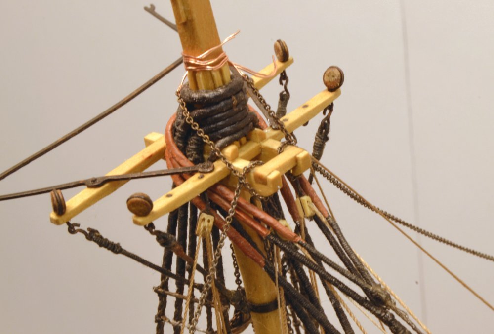
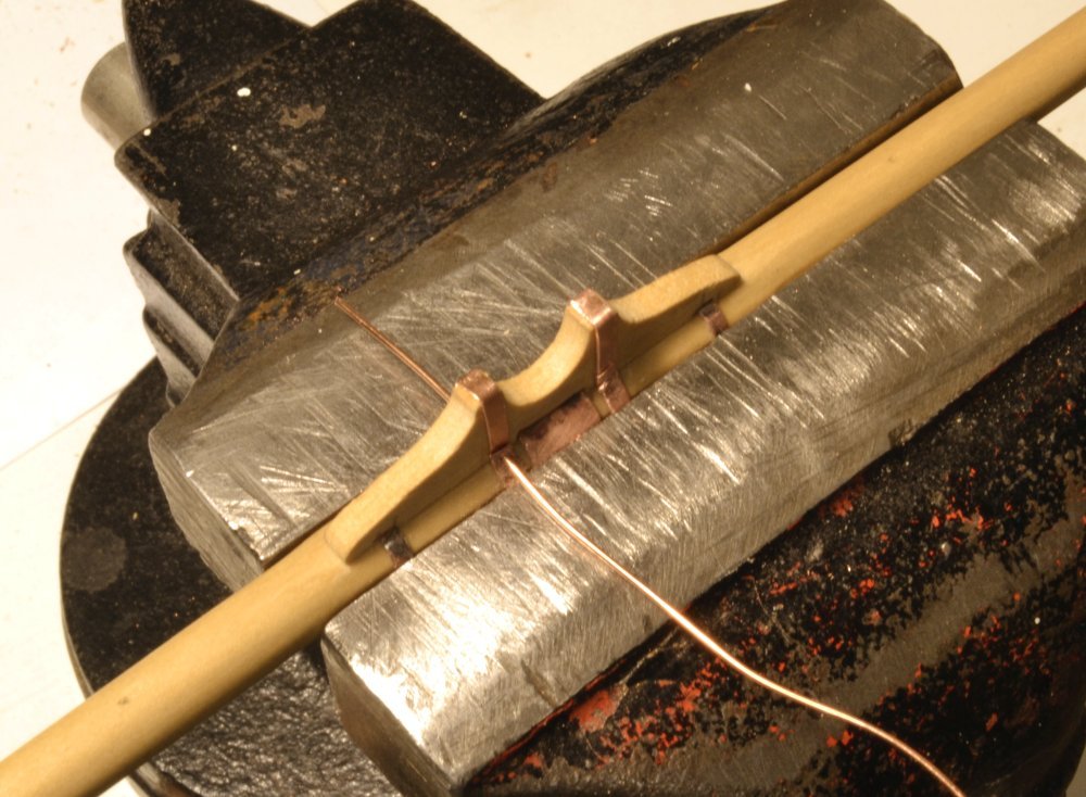
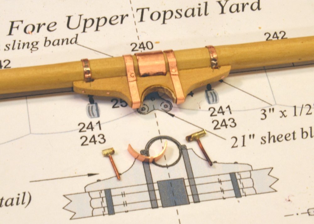
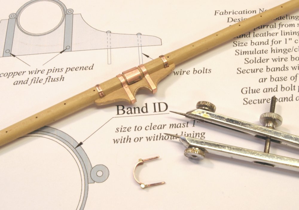
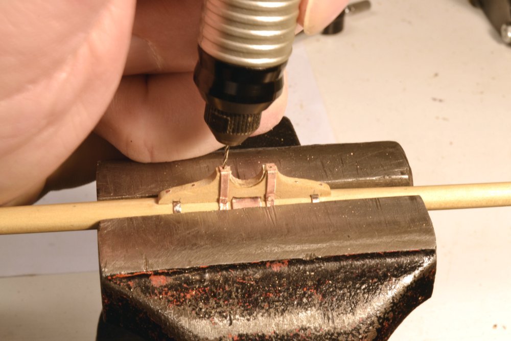
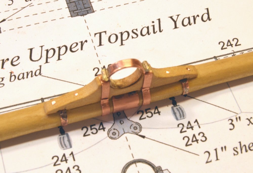
Young America - extreme clipper 1853 Part 269 – Fore Upper Topsail Yard Parral 2: Ironwork In the first picture the wood yoke has been glued to the octagonal flat on the aft side of the yard. One of the bands that reinforce the connection of the yoke to the yard has been fitted and the other is shaped but awaiting attachment. All "iron" fittings on the yard are copper, to facilitate later blackening with liver of sulfur solution. The uninstalled band shown in the picture was shaped around the yard and yoke. It includes a short overlapping tab that will be used to through-bolt the band using a copper wire bolt. In the next picture one of these bolts is being inserted through a drilled hole at the base of the yoke. The short tab is located on the underside of the yard – out of sight. The copper wire shown was next clipped just above the surface on both sides of the yoke and peened to form a tight connection. The next picture shows the upper side of the banded parral. The next picture shows the underside of the yard/parral and parts of the hinge/clasp that will hold the yard to the mast. To simulate the hinge/clasp fitting, short lengths of wire were drilled to accept copper wire pins that will slip into holes in the parral. The wire pins were soldered into the holes. The piece on the left has been filed to shape. These assemblies were then silver soldered to the half-circle band as shown in the next picture. The picture shows dividers that were set to the spacing between the pins and used to mark the bands on either side of the circular yoke opening. The above two pictures also show simulated leather lining in the opening. This was made from dyed heavy paper glued to the wood. In the next picture the spaced holes are being manually drilled to receive the long copper pins. I drilled these manually to avoid disturbing the boring setup on the milling machine described in the last part. There are never enough tools. The last picture shows the completed parral except for blackening and fitting of the lining on the hinge/clasp. Copper wire bolts have been driven through the arms of the yoke into the yard to simulate those used originally and to provide additional strength. Next, the rest of the ironwork on the yard will be added. Ed
- 3,618 replies
-
- 36
-
-
- young america
- clipper
- (and 1 more)
-
Thanks for the comments and all the likes. I hope to be putting the second part on the parrals later today. Frank, the centering method using telescoping tube is a real time saver and is certainly adequate for our work. As you will see, it has advantages over the more conventional dial indicator methods - its faster and requires less effort - and contortions to read the indicator in each rotated position. Good luck with it. Ed
- 3,618 replies
-
- 1
-
-
- young america
- clipper
- (and 1 more)