


EdT
-
Posts
2,214 -
Joined
-
Last visited
Content Type
Profiles
Forums
Gallery
Events
Everything posted by EdT
-
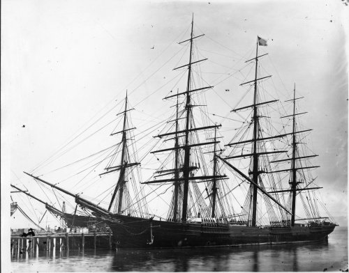
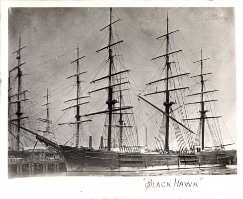
That is my understanding, wefalck, in fact here is one of the photos of Young America where she is docked in New York with her main yard topped up and another of Black Hawk. In this position the yards could also be used for handling cargo, I believe. Comments on this last point welcome. Ed
- 3,618 replies
-
- 8
-

-
- young america
- clipper
- (and 1 more)
-
Druxey, I meant to comment on your comment. The forward extension of the truss from the mast really helped with bracing of these yards by increasing the range of rotation before interfering with other rigging. I don't know what the actual extension on Young America was, but another ship of the type was documented to have the yard 7' forward of the mast on a truss of this general type. The lower topsail yard will also be hung forward of the cap by about, I think, 4 feet - on a similar swivel truss. Roger, just another comment. although the starting point in forming the truss was a 1/8" plate, the final shaped size is smaller, perhaps on the order of 6" - still a lot of iron. Ed
- 3,618 replies
-
- 4
-
-
- young america
- clipper
- (and 1 more)
-
Hello, Gary. It is good to see that you are still tuning in and keeping an eye on us. Miss your posts and contributions. Ed
-
Thanks, everyone, as always for the likes and comments. Roger, I would assume that the trusses of this type would be forged, and would be well within the capabilities of the time. Hammers by this time were often steam driven and I assume a large yard like Webb's would have the necessary equipment, or these may have been contracted out. Consider, for example, the forging of anchors back well into the 1700's. There seem to have been many shapes for these trusses, and sometimes it is hard to distinguish between simplified drawings for patents or in treatises and actual practice. Some may have been bent bar, but I suspect these would be more common on smaller craft. These are mainly large universal joints, with the weight of the spar being taken on the chain sling and, in the case of lower yards, some on the topping lifts. Ed
- 3,618 replies
-
- 5
-
-
- young america
- clipper
- (and 1 more)
-
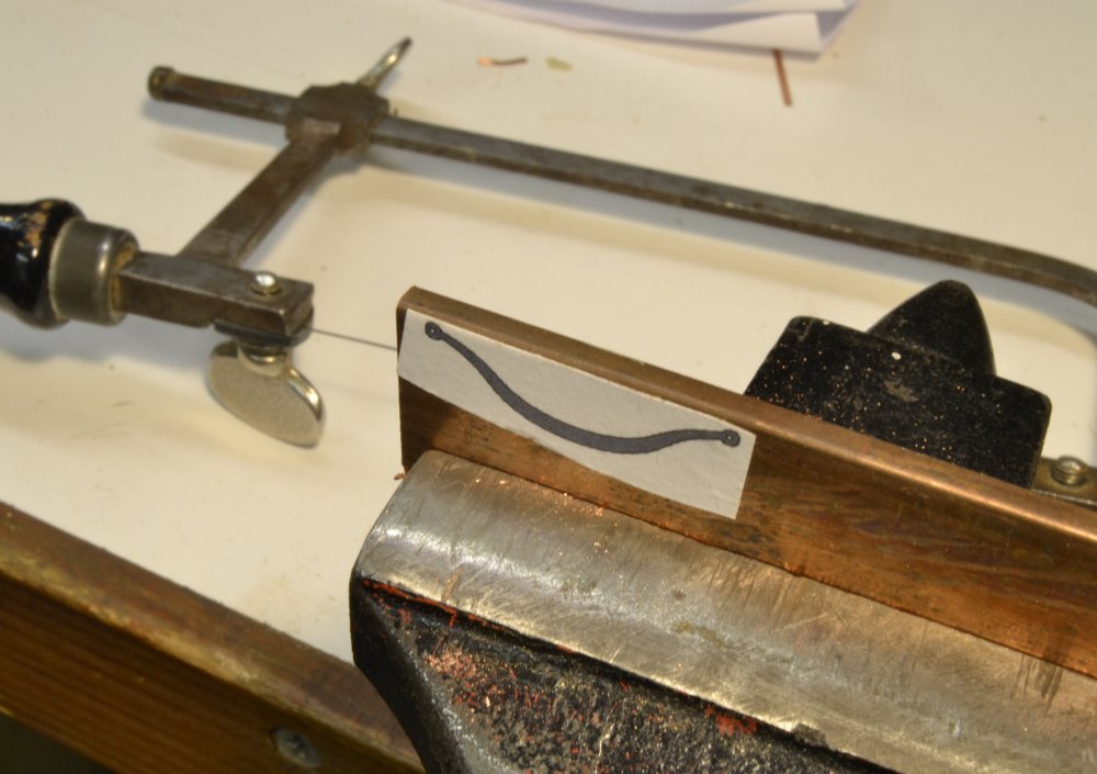
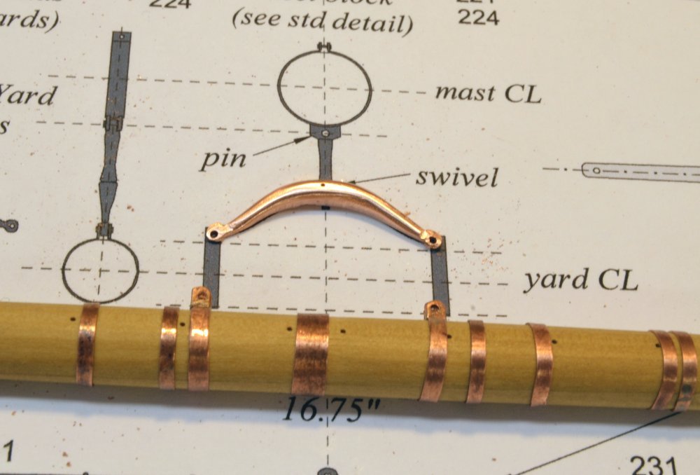
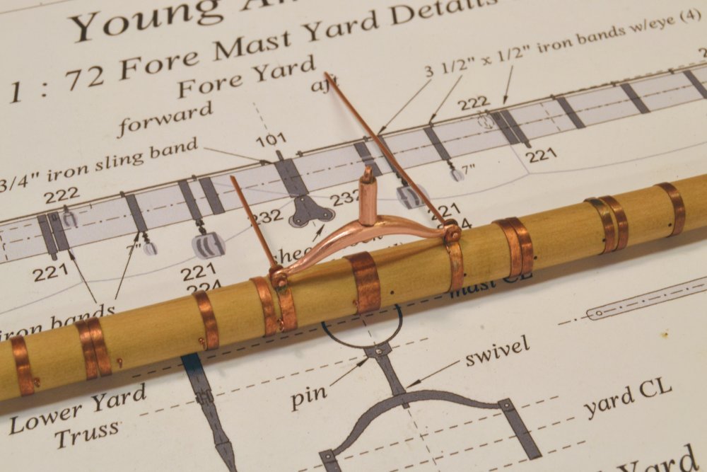
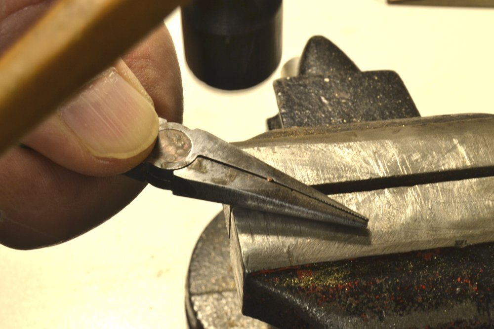
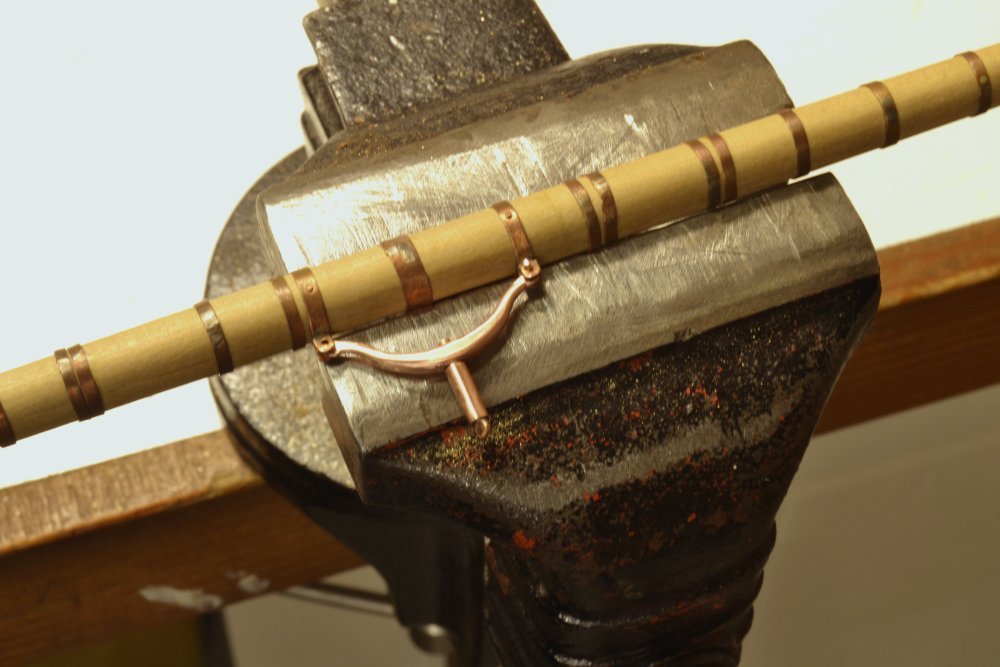
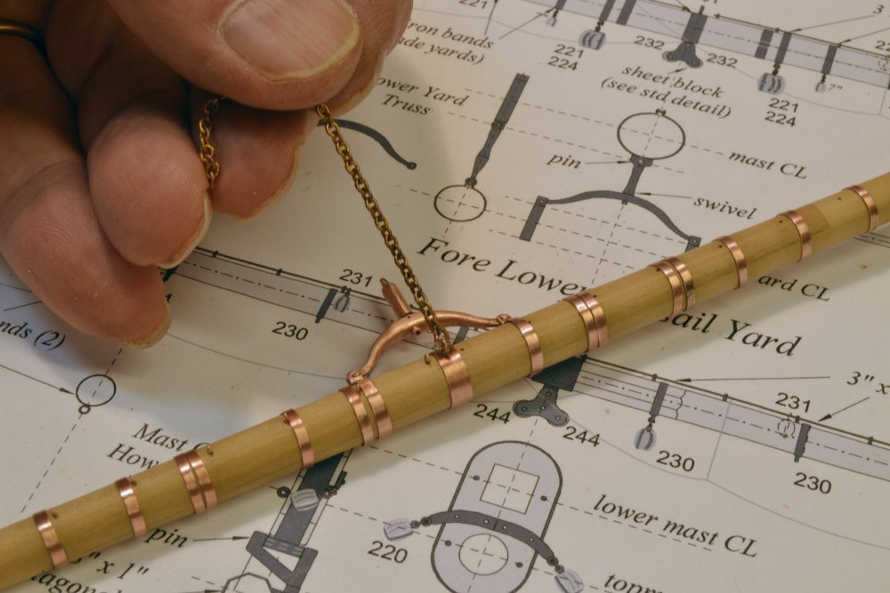
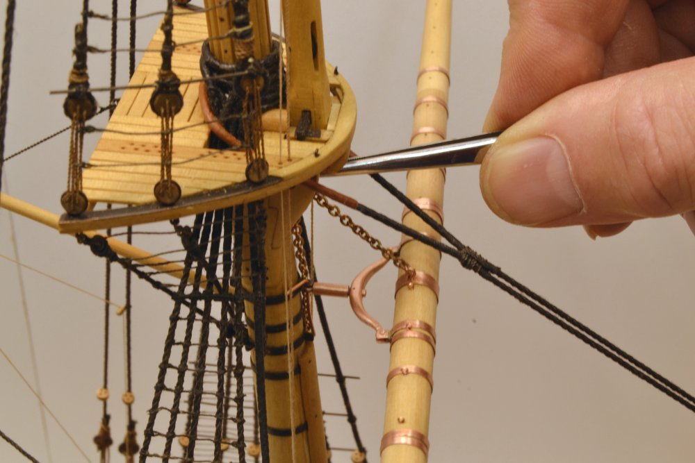
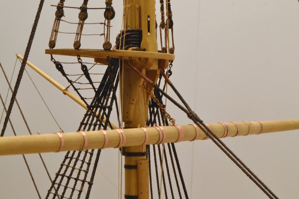
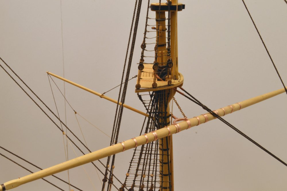
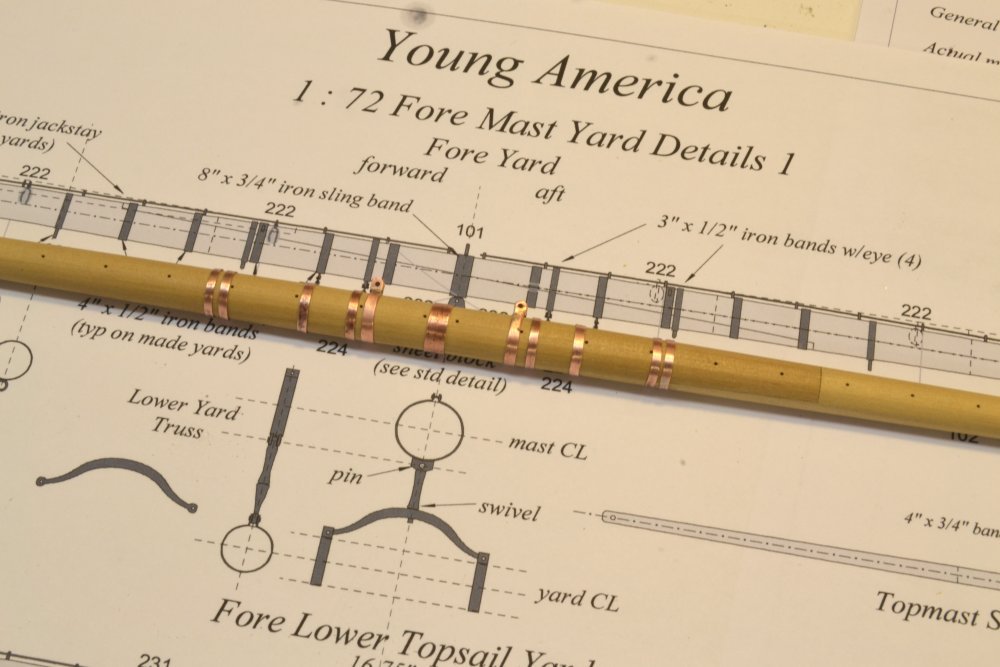
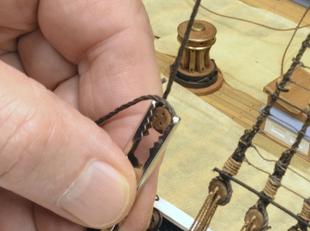
Young America - extreme clipper 1853 Part 250 – Fore Yard Truss Lower yards on ships of this type were attached to the masts using iron trusses. The fore yard truss will position the yard about 6 feet forward of the mast. It is configured in the form of a universal joint that allowed the yard to be "braced", that is, rotated around the mast, or "topped," raised at one end or the other. The weight of the yard was taken mostly by a separate chain sling shackled to the center of the yard and bolted to the mast just below the hounds. Making and fitting of both these parts are described below. A pattern for the yoke that connects the truss to the yard is pasted to a 1/8" copper plate in the first picture. This curved yoke lies in the horizontal plane, has vertical holes at the ends for bolting to yard band brackets and horizontal hole through its center for a bolt to a universal fitting that will allow vertical rotation and topping. The shape of the yoke was first cut out using a jeweler's saw, then filed to a rounded shape. The next picture shows the shaping in progress and the yard band bolt holes drilled. The wide band at the center of the yard will be drilled for the sling eyebolt. The next picture shows the universal fitting bolted through the yoke. It has an eye at the aft end to fit the bracket in the mast band that was installed earlier. In the picture, two long wire bolts have been inserted through the yard band brackets and yoke eyes. These were first peened to form rivet heads as shown in the next picture. The pliers in the picture have half-round slots filed into the jaws that allow wire to be held for peening of the end. I believe this process was described earlier, perhaps in a Naiad post. In the next picture one of the long bolts has been clipped off on the underside, leaving just enough for its head to be peened, locking the yoke arm to the bracket. A flat-end center punch was used for this. The other bolt was then inserted, clipped and peened to complete the attachment. Unfortunately I did not take photos when making the universal fitting, so a description of that will await work on a later mast. Note in the picture that the yard bands are pinned to the underside of the yard with small copper bolts. The weight of the yard, as mentioned above was mostly taken by a chain sling. This is shown in the next picture, shackled at one end to an eyebolt temporarily inserted through the central yard band. To set the length of the chain, the yard was temporarily hung and the chain held with tweezers as shown in the next picture. The tweezers were used to hold the chain at a link that could be fitted with an eyebolt into the mast that would hold the truss level. The chain was cut at this point and an eyebolt spun onto it. The hole for the eyebolt was then spotted on the mast, again by holding the eyebolt with tweezers and marking the height that would hold the truss level. The next picture shows the yard hung temporarily with eyebolts inserted. The next picture shows the yard fully braced around to the point where it contacts the forestay and almost touches the forward lower shroud. There is still much work to do on this yard before installing it permanently, some of the parts were shown earlier. Others will be described in the next parts. Ed
- 3,618 replies
-
- 41
-
-
- young america
- clipper
- (and 1 more)
-
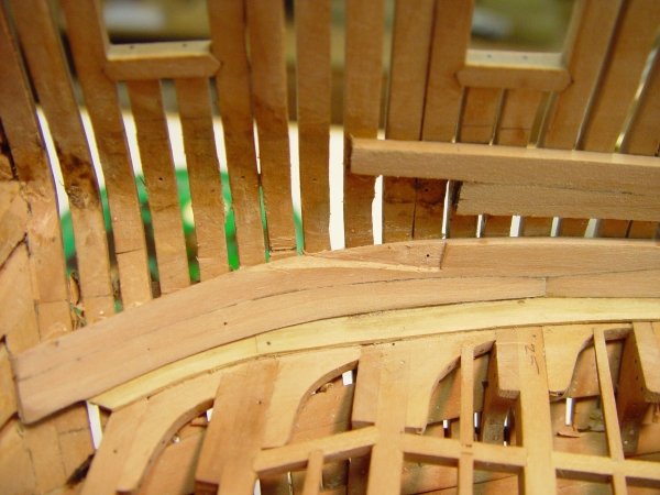
Hello. Mark. These are all interesting and challenging drafting riddles that were undoubtedly never dreamed of in the shipyard. At this stage of a problem like this, I usually say, "Ed, think like a shipwright." My starting point would probably be to make and fit one, then make the adjacent one to fit it. At least some of this fitting would be after bending the planks. Just a suggestion from someone who delights in drafting true views of strange shapes. Cheers, Ed
-
Thank you, Alberto, Druxey and Pat, and all others for the likes and thanks Pat for the book purchase. The hardware on these yards is a lot of work and this first one has been languishing on the bench since the summer, while I tried to find the best way to move it forward. Big step forward yesterday, completing fabrication of 7- 21" cloverleaf sheet blocks for the seven larger yards. Next the 8 - 15" versions, but these may wait until I make the iron cheek blocks for the large yards. I am very anxious to get this first yard hung. Thanks again. Ed
- 3,618 replies
-
- 8
-
-
- young america
- clipper
- (and 1 more)
-
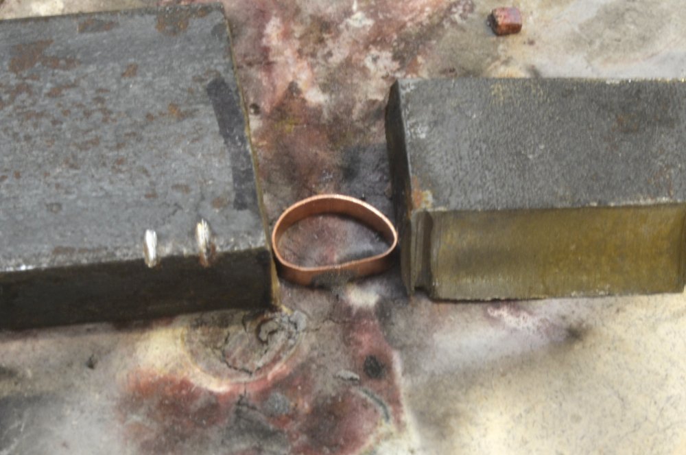
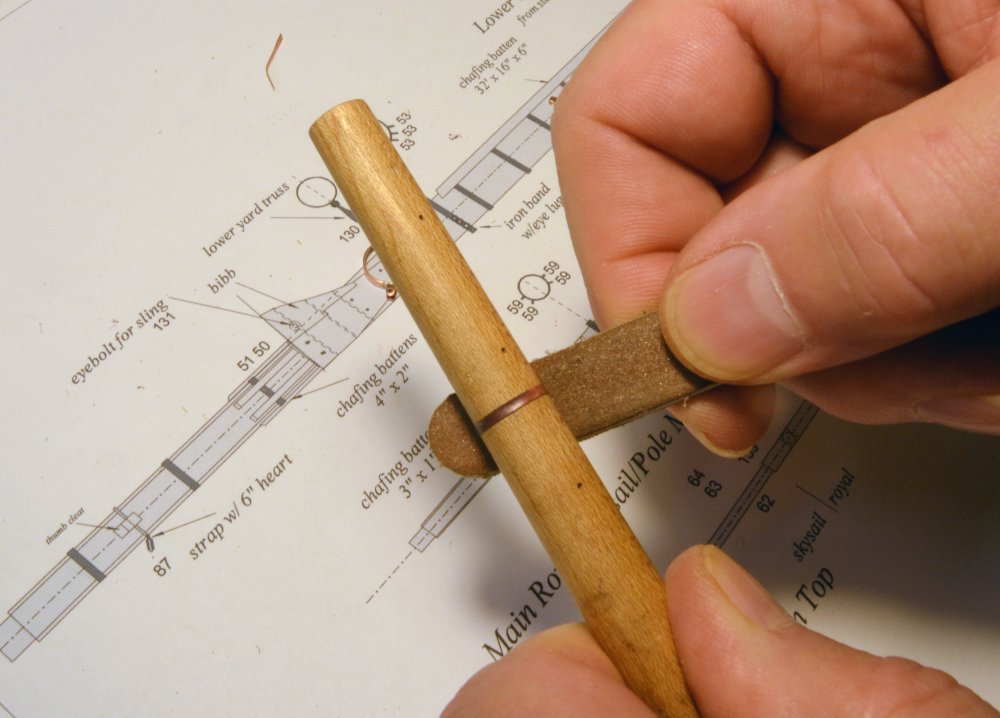
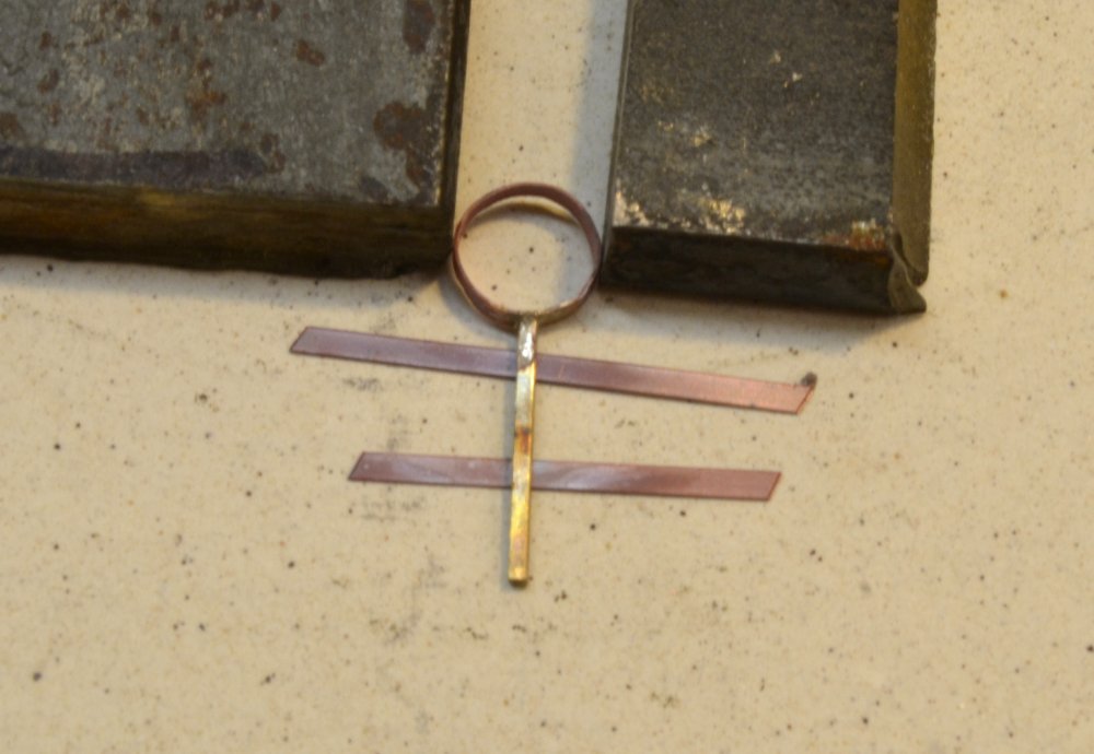
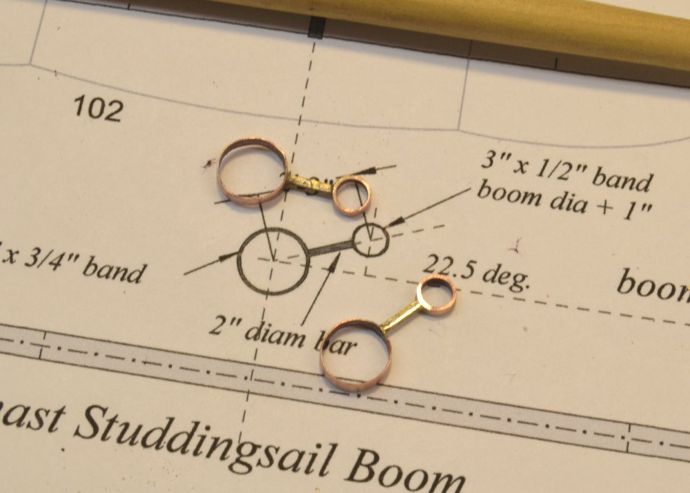
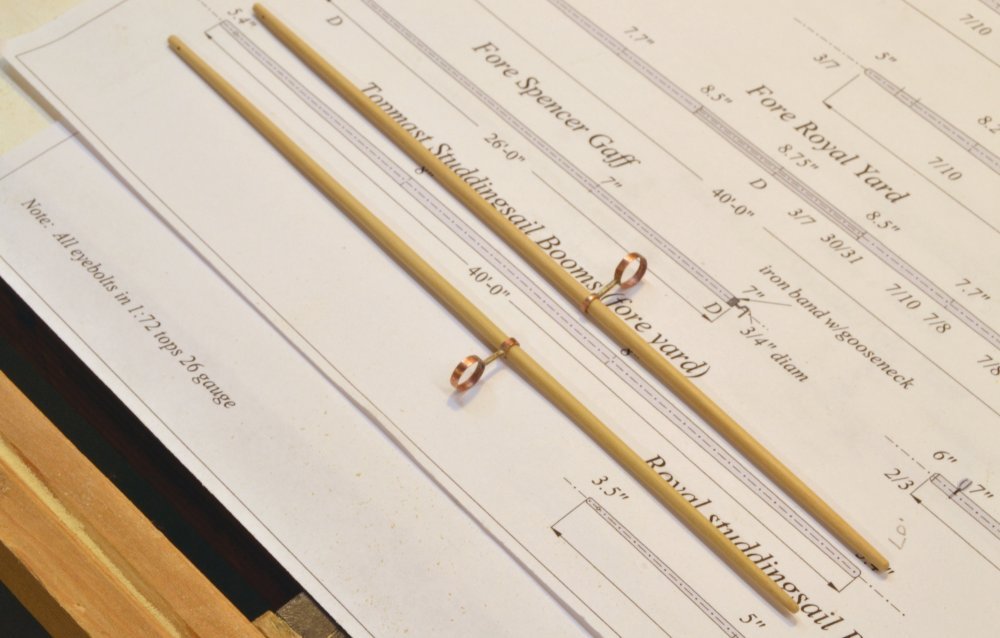
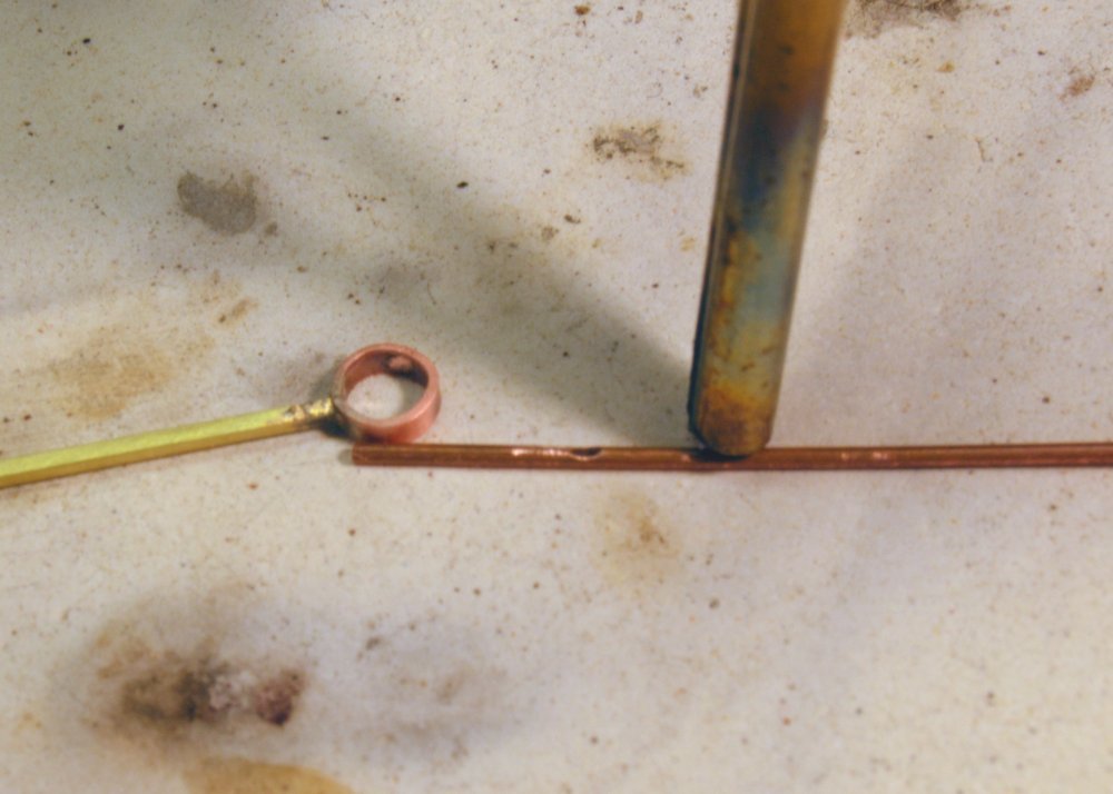
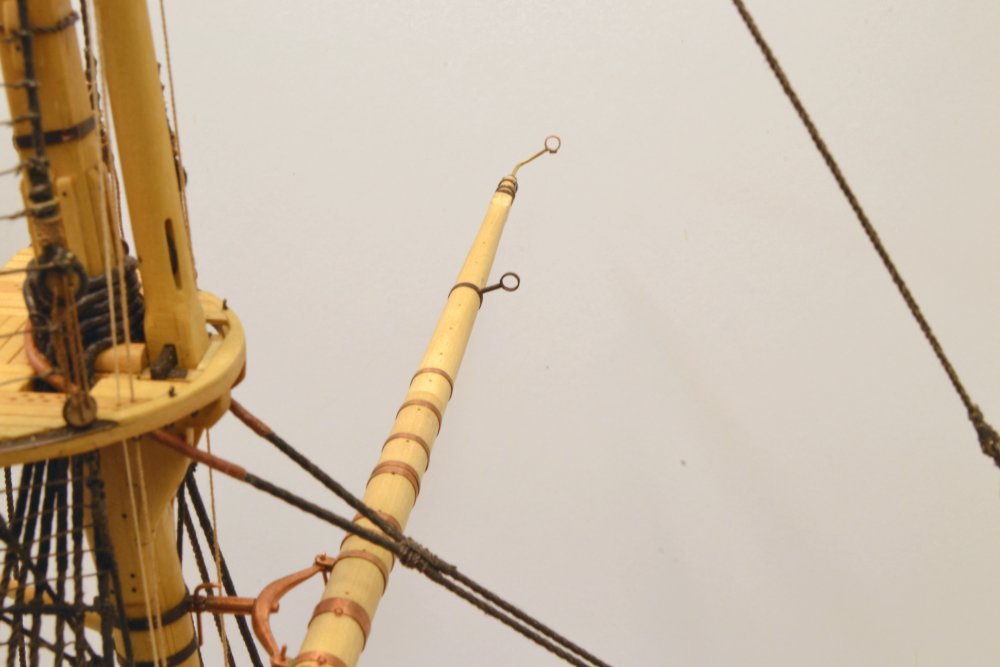
Young America - extreme clipper 1853 Part 249 – Lower Fore Yard 3 There is a variety of ironwork to be installed on every square yard. Beginning with the iron sling band at the center and the reinforcing bands on made yards. These and other bands, as well as some structures attached to bands, like studdingsail boom brackets, must be sized to each individual yard. Others, like iron sheet blocks that hang from the center of the yard, cheek blocks for sheets at the yardarms and to some extent iron trusses, are more standardized and lend themselves to a "mass production" approach, if making seven or eight identical parts can be considered "mass." So, while the work shown in this part and the next was able to proceed, progress was soon hindered until a batch of standard parts could be produced for all the yards. Developing processes for those has taken some time and this has slowed work on the first yards. This and the next part describe work on the fore yard before interruption to make sheet and cheek blocks, to be described later. The first picture shows iron (i.e. copper) banding at the center of the yard. Most of this is ½" thick x 4" wide – actually slightly thicker (.010"). The center sling band is thicker (.015") – and wider. It will eventually be drilled top and bottom to secure eyebolts for the chain sling and the sheet block. Outside of that are two more thicker bands that will secure the iron yard truss, then the first reinforcing band, a band to secure a block, then a band than will attach a sheet fairlead, then two more bands, one reinforcing and one for a block. Additional bands were added out to the first studdingsail bracket that is described below. But first, the basic banding method. This was described in an earlier post. The first step is cutting banding material to a length that will form a ring slightly smaller than the yard diameter at its location. Some ways to do this were described earlier. The ends of the band are then butted together and silver soldered. A soldering setup to keep the ends together is shown in the next picture. Two steel blocks were used for this. After soldering, the misshapen bands are then pushed on to a wooden mandrel to shape them and provide a holder for filing (if needed), smoothing, and polishing as shown in the next picture. Using a separate mandrel for this helps keep the spar clean. This one is maple, one of a pair in different sizes to be used for this purpose. The mandrel may also be used for sizing bands. This was described in Part 184. After this step the band is fitted to the yard, with the last ¼" or so a forced fit. The next picture shows fabrication of a studdingsail boom bracket. The band is made a fitted to the spar first. The square piece of hard brass is the silver-soldered to it as shown in the picture. The two brass bands under the brass leg are used to center the leg on the band width. The leg is then cut to length and the outer bands for the booms soldered on. These are test fitted to the studdingsail booms as shown in the next picture. The outer boom irons are made in a similar way, with the addition of a simulated roller on the bottom side of the boom band. The next picture shows the setup for soldering the roller to the bands. The rounded out area on the copper wire will be placed under the band in the final setup before soldering, after clipping off the wire. This is a simplified simulation of the actual roller, which would be on an axle within the band diameter. In the last picture, the outer arm has been bent and inserted into the end of the yard and shown with the yard temporarily mounted. There is more work to do on these parts, including blackening. Also, the reinforcement of the yardarm is not shown. This includes a u-shaped band wrapped around on the axis of the yard and two circular reinforcing bands over it. I will show pictures of this later. Also, this photo shows the yard truss that will be described in the next part. Ed
- 3,618 replies
-
- 36
-
-
- young america
- clipper
- (and 1 more)
-
Thank you, Pat. The copper will, of course be blackened later to simulate iron, but there is a lot more of it to go on this yard before then. Thanks, everyone for the likes. Ed
- 3,618 replies
-
- 3
-
-
- young america
- clipper
- (and 1 more)
-
Mark, the two planing beds, one with cams the other V-grooved, are 3 1/2" x 3/4 pine planks that rest at the ends on 3/4" thick strips and are screwed through these into a 2 x 4 (i e 1 1/2" x 3 1/2" w) - for stiffness. Near the center of the bed are two screws through holes in the bed into the 2x4. Tightening these screws depresses the bed in a curve in the center. A 3/4" shim is used under the center of the bed to restore it to a flat state when the screws are loosened. The 2 x 4 is vise mounted. Ed
- 3,618 replies
-
- 9
-
-
- young america
- clipper
- (and 1 more)
-
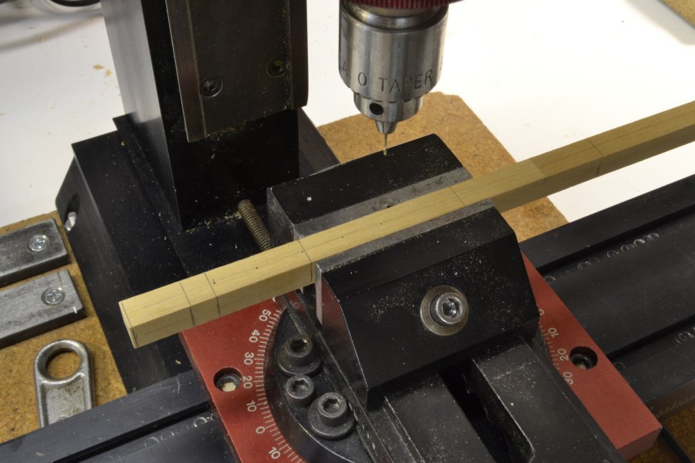
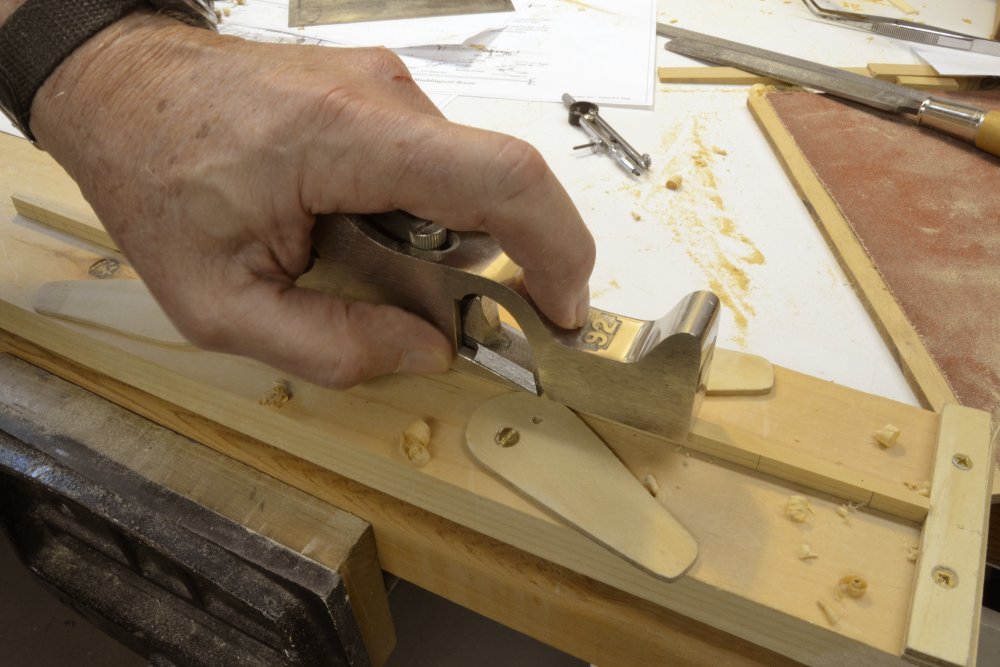
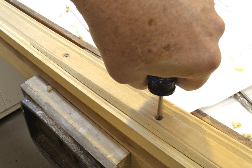
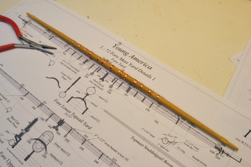
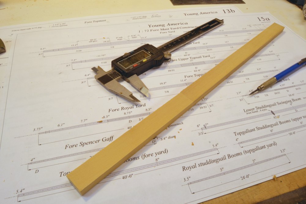
Young America - extreme clipper 1853 Part 248 – Lower Fore Yard 2 The assembly shown in the last picture of the last post was slit into two and the one for the fore yard downsized to make the 22" squared "first trim" for this spar. In the first picture holes along the centerline of the spar, in this case jackstay eyebolt holes, are being drilled in the still-square spar. This method and the alignment of the vise using a center-finder was described in Part 226. Using the center-finder helps locate the holes on the precise centerline. Pencil marks for the quarters, the square near the end of the yard, and the end of the yard arm may be seen in this picture. The next picture shows the second trim, that is, the tapering of two of the four faces. In the next picture the spar is clamped in the planning fixture and one of the two remaining faces is being planed. The next picture shows the completed third trim, with all four faces tapered but still square in section In the next picture the spar has had the corners of the octagon shape scribed with the tool described in an earlier post and the V-grooved planning fixture is being adjusted to prevent the now-curved spar from rocking. This adjustment uses screws to depress the center of the bed to the shape of the spar. All four corners were removed and the spar rounded on this fixture. The following picture shows the spar with the first few "iron" bands fitted. Because this is a made spar, it is round in section through the center to allow shrunk-fit reinforcing hoops to be installed to hold the assembly together. These bands plus a variety of others will be fitted, beginning at the center and working outward. The bands are made small enough to be force fit into their final positions. Ed
- 3,618 replies
-
- 33
-
-
- young america
- clipper
- (and 1 more)
-
Saw blades for Byrnes saw
EdT replied to mikeaidanh's topic in Modeling tools and Workshop Equipment
Carbibe blades are not needed for most model work, with the exception being thick hardwood stock. HSS Slitting saw blades are more economical, available in a range of blade thicknesses, and safer to use for small work. Ed -
Mark, Naiad did not have the intricate shapes that the larger ships seem to have had. I used standard anchor-stock shapes and boiled.bent them to fit, sometimes with some post drying trimming - as I recall. You may take a look at parts 88-90 in the Naiad b log. Ed
-
Thank you, Maury. A 22' diameter yard would be something to see. No mastery at work here, Maury. I am perfectly willing to add small details if they are easy to do, more difficult ones, not so much. The scarph was much easier to do for me than trying to scribe a line for the joint - well beyond my competence. While the joint itself will not be too prominent, the round center section of the yard on the original ship (not octagonal) that was needed to accept the shrink-fit hoops might raise some questions with no joint showing. So... Thanks for staying tuned and thanks to all for the other comments and likes. Ed
- 3,618 replies
-
- 7
-
-
- young america
- clipper
- (and 1 more)
-
Hi Tim, Cutter is 4-fluke but I most likely HSS, I'd have to check, but HSS is fine for wood. Speed is up at or near the top of the Sherline range - 2500 to 3000? Wood is Castello. Ed
- 3,618 replies
-
- 2
-
-
- young america
- clipper
- (and 1 more)
-
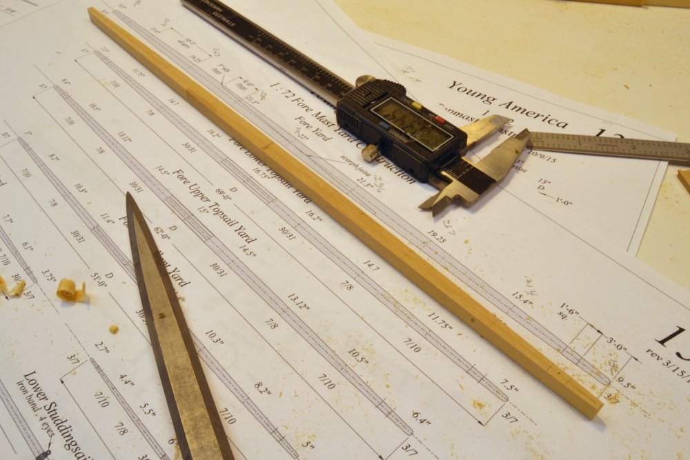
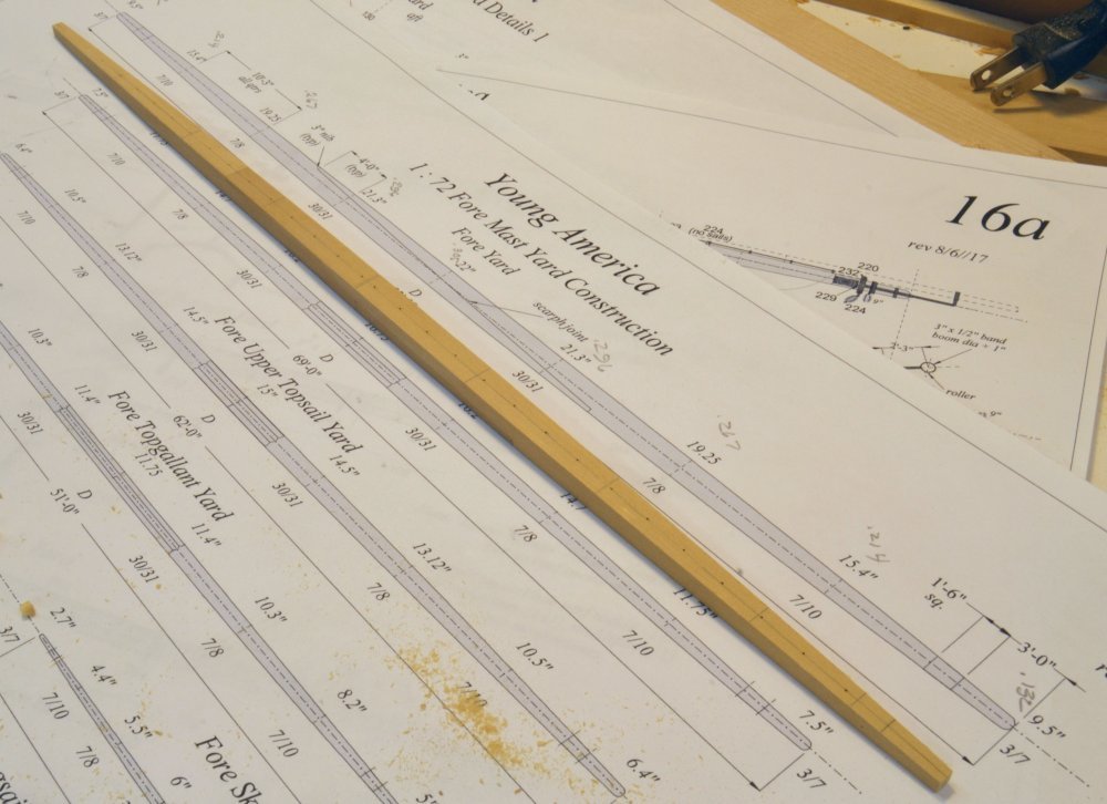
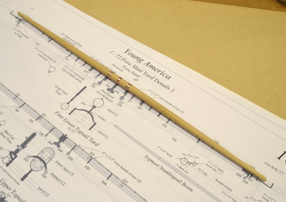
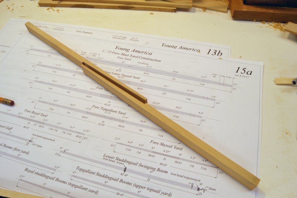
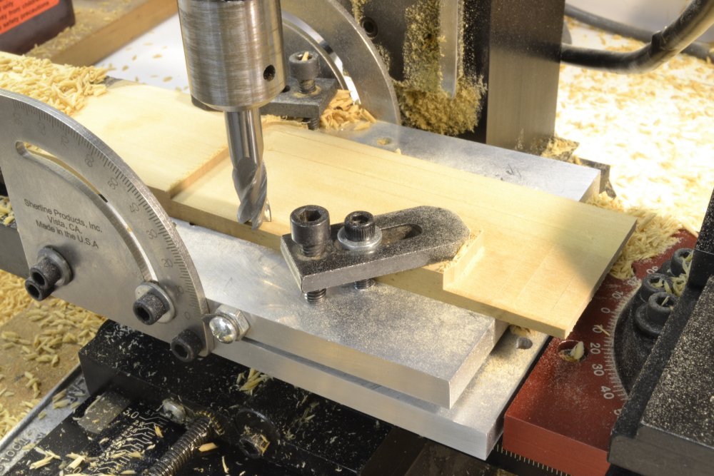
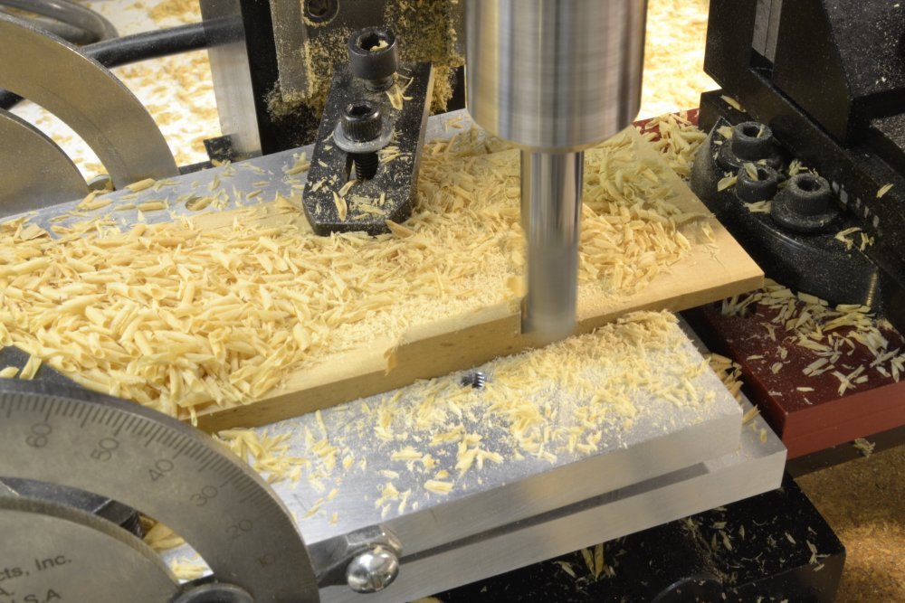
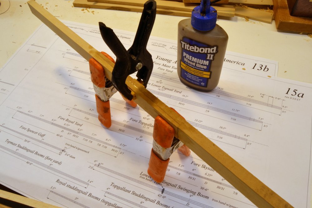
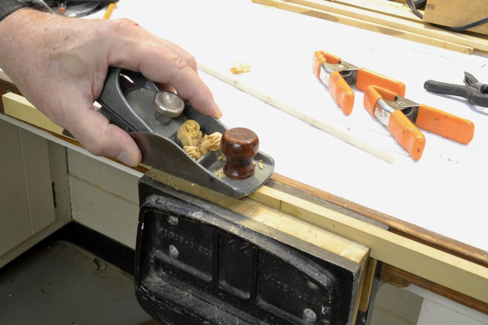
Young America - extreme clipper 1853 Part 247 – Lower Fore Yard 1 One of the nice things about this stage of the project is that many directions may be taken in the construction. I could, and will, be ploughing on with the shrouds, stays, and ratlines on all three lower and top masts, but for my own sanity and for the interest of those following this log, other work is on the agenda. One of these directions is the square yards for the masts now installed. Apart from being different work, this will open up other areas, like the standing and running rigging for these yards. But before yards can be fitted, they must be made. A lot of work is involved. The spars themselves are straightforward, but making the array of yard fittings – trusses, cheek blocks, cloverleaf sheet blocks, studdingsail ironwork, etc. - will be a major task, some of these parts will be "mass produced" and some fabricated one yard at a time. Making and fitting out the 18 square yards is the largest of the remaining tasks to complete the model. The lower fore yard was the first to be made. In the first picture, the yard is shown with its structural ironwork – the bands that hold this "made" yard together – plus some bands that had to be fitted first, like the sling band, the truss bands and the fairlead bands that go between structural bands. This yard and the main yard are "made" from two pieces joined by a long scarph. The fore yard was 82' long and 22' in diameter at the center. The main yard was slightly larger. This size yard would most likely have been an assembly of two trees, perhaps more. Both these yards will be made yards on the model. The next picture shows two scarphed pieces before assembly. These pieces were made wide enough to be used for both the fore and main yards. After gluing up and squaring, they will be slit to form the squares for the two yards. The next picture shows the scarf been milled in a plank wide enough to produce the two pieces shown above. The angle of the scarph is only about 2.5 degrees. The Sherline tilting table was used. In the picture most of the surface has been milled. To complete the work the clamp will be relocated to an already milled location. The next picture shows the final milling step. A 3/8" diameter end mill was used. With the tilting table this is a simple milling task - once the correct lip depth has been set at both ends of the joint. In the next picture the milled plank has been slit in two and is being glued together with dark glue. In the next picture the glued-up piece is being planed to level and square one side. This piece was then passed through the thickness sander to level both sides and reduce it to the size of the larger main yard. This will then be slit and one piece further reduced to the size of the slightly smaller fore yard, which will then be shaped. Ed
- 3,618 replies
-
- 28
-
-
- young america
- clipper
- (and 1 more)
-
Mark, I would concur with the scarph arrangement you have shown - the first one. You may not need the contract specific to Bellona, but only one from her era and for the general 74 class. These may or may not exist for her time, or if ships of this type were all built in Admiralty yards. Frigates were commonly contracted out. Contracts I have were specific to the frigate type but were fill-in-the-blank on dimensions. I used the contract for the Artois class, but the text is identical for smaller classes of frigates. I recall Gary B (garyshipwright) having a collection of contracts for 74's so they must have been used at some point and something close should be obtainable. Ed
-
Some additional thoughts: The standard-form frigate contract of the late 18th Century contains the following spec: "To have a wing transom knee on each side 10 inches sided, the knee fore and aft arms 14 feet 0 inches long, the athwartship arms 7 feet 0 inches long, to hook with a long hook scarph to the spirketing and bolted with 13 bolts of 1 1/2" diameter, and 2 of 7/8" diameter in the lip of the scarph." It is true that this is a frigate contract, so it may be different for a 74. If you have contract for the larger ship I would be interested in the text. If not, I suggest getting one from NMM. The question is: what is the orientation of the hook scarph - horizontal or vertical? With the number and size of the bolts I put it in the vertical plane, simulating it with a wide score into the spirketing, since such a hook scarph in that plane is invisible - and hard to cut in situ. Whether the fore and aft arm of this knee is straight or curved would, I guess, depend on the relative heights of the transom vs. the spirketing. In my case the spirketing was lower so the knee was curved to allow the knee leg to enter the spirketing scarph (score) on a parallel line. On Naiad (see the photos) the knee if left straight could easily have been scarphed into the deck clamps above the spirketing, but that is not what the contract says, so I did not do that. Actually from the glue residue on the frames, I may have first bolted it directly to the frames then changed it after reading the spec. Can't recall. Edited-an after thought on the curve knee: Curving the knee so that the top face of the short leg is parallel to the wing transom, permits bolts to be driven through. Angling it down might preclude this. I cannot recall if I had other reference(s) for this. I think it was just the contract language cited asbove. Ed
-
That is my interpretation as well, Druxey. Here are two photos from the Naiad build log showing how I interpreted that. First the score in the spirketing. Then the installed transom knee with the s-curve into the spirketing score. I did not plank this side under above the structural spirketing. Hope this helps. Ed
-
Nice idea for the small pieces, Mark. As for the hand scroll saw, I'll take your word for it. Ed
-
To be honest, Tom, I have a hard time visualizing it until actually doing it. Thanks again for your comment. Ed
- 3,618 replies
-
- 3
-
-
- young america
- clipper
- (and 1 more)
-
Thanks, again, everyone for all the comments and likes. I realize some of the posts are becoming repetitive - a prime descriptor for rigging work - but I hope to have some new work to show soon. Tom, I am no expert on knots, so your comment propelled me back to the experts, starting with Darcy Lever and coming forward to S.B. Luce and Biddlecomb. Everything after Lever seems to be a copy of his descriptions - in which he and his successors describe a clove hitch as two half hitches. Since I am making these seizings with three (and sometimes more) half hitches, the term clove hitch is technically incorrect. I should probably describe these as three (or more) half hitches. In all cases the rope is taken around in the same direction. In any case this method of making seizings is a modeling convenience at this scale that simulates actual seizing methods where a number of turns are taken then secured with perpendicular frapping turns between the larger ropes. Ed
- 3,618 replies
-
- 1
-
-
- young america
- clipper
- (and 1 more)
-
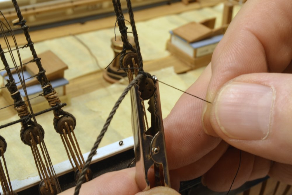
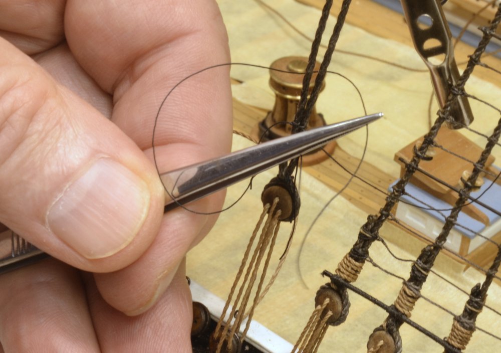
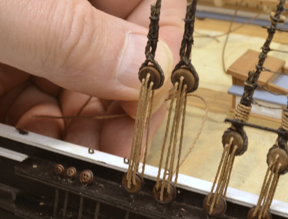
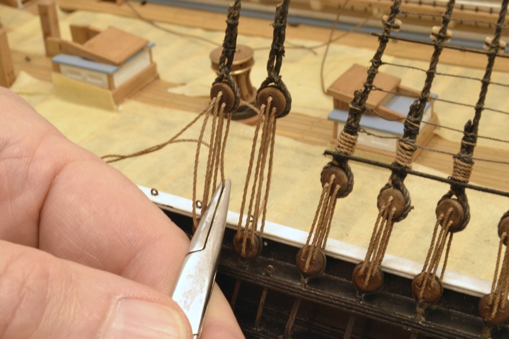
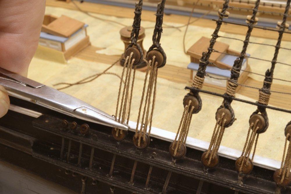
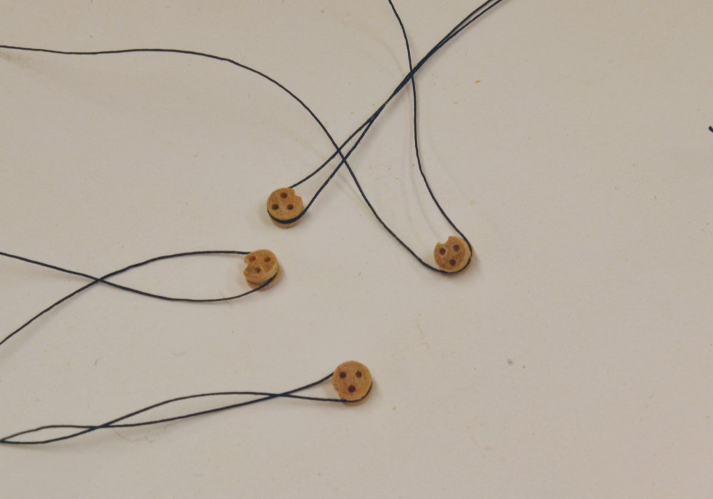
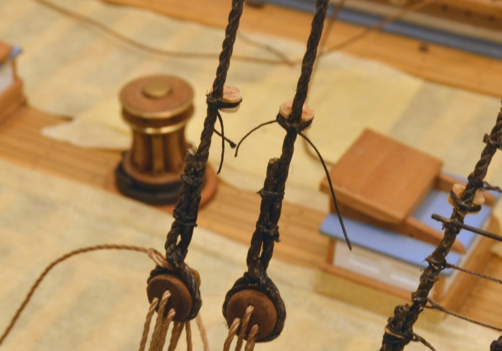
Young America - extreme clipper 1853 Part 246 – Main Topmast Backstays The main topmast backstays are exactly like their foremast counterparts – two pairs of 10 ½" lines looped over the topmast head and secured to the channels with deadeyes by 5" lanyards. The alligator clamp holding one of the 16" backstay deadeyes in the first picture was very useful when tying the throat seizing and in setting the deadeye height. The throat seizing is being tied in the next picture. The two round seizings above the throat were made with a series of clove hitches. The easiest way that I have found to tie each hitch on these and on the ratline knots is shown below. After tying an overhand knot one one leg of the stay the tweezers are placed through the loop in the line that is passed behind the stay. The tweezers are then used to grip the end and pull it through to form the hitch. This process goes very fast and yields a tight seizing from the first hitch. I am using three hitches on these. The threading up of the aft deadeye lanyard on this side is being completed in the next picture. The first tensioning is started in the next picture. The linen lanyards are pretty stiff, so pliers are used to grip each leg in turn, pulling up on the inboard legs and down on the outboard until all four stays have about equal tension and the forward stay is taut as well. In the next picture the upper aft deadeye is being adjusted to make its face parallel with the stay. This can be done by gripping all three of the outer lanyard legs and raising or lowering them until the deadeye faces are aligned. The next picture shows the four fairleads for these stays ready to be lashed on. The lashing thread was first glued to the perimeter groove on the inboard side to make these easier to lash up. The last picture shows the two starboard fairleads installed The loose lashing ends will be trimmed later. The lanyards will be wound around the stay later after a final tension adjustment in a week or so. Ed
- 3,618 replies
-
- 30
-
-
- young america
- clipper
- (and 1 more)
-
Thank you, Johann. I am beginning to appreciate how tall this ship was. There are two more masts to be added on both the fore and main masts (and 3 on the mizzen). Ed
- 3,618 replies
-
- 4
-
-
- young america
- clipper
- (and 1 more)
-
Thanks, everyone for the comments and likes. I know about that hook, Micheal. Sometimes photos show what you otherwise don't see. Its on my list to be corrected. These hooks are 26 gauge wire, but stand up pretty well to the tension on the lines - although they can be over-stressed and perhaps this one was. Thanks for your eagle-eye. Not a lot gets overlooked in these close-up photos - but that can be helpful. Ed
- 3,618 replies
-
- 8
-
-
- young america
- clipper
- (and 1 more)