


EdT
-
Posts
2,214 -
Joined
-
Last visited
Content Type
Profiles
Forums
Gallery
Events
Everything posted by EdT
-
Yes, Wayne, as I'm sure you know, those little drawing objects do go astray and often pop up in unintended places. What would we do without them though?
-
Sorry, Rob. I didn't consider it a rebuttal - merely an explanation.
- 3,618 replies
-
- 1
-

-
- young america
- clipper
- (and 1 more)
-
As a side note on my non-linear, iterative research, drafting, constructing sequence and the resultant use of drawings that are not necessarily final, you may note that in the pictures of the last post that the martingale has been drilled for an eyebolt above the cleat slot and that the drawing shows such an eyebolt. There is no such eyebolt. The one shown is a renegade CAD object that somehow got dropped at this location and was never deleted. A rare occurrence for sure, but part of the baggage of the process. Ed
- 3,618 replies
-
- 8
-
-
- young america
- clipper
- (and 1 more)
-
Thanks, everyone for the comments and likes - very much appreciated. As to the questions.... Frank, I used a minimum of marks to shape the cleats. First, with the plate inserted, the outline of the spar was scribed, then the ends of cleats. The shape was then rough-cut by eye with the jeweler's saw and filed to final shape. Rob, the jibboom/flying jibboom geometry is based on proportions from Crothers and the spar list for the ship. Crothers describes his primary source references. The positioning of this spar follows from the proportions, with the forward end of the untapered section coinciding roughly with the cap. The drawing seen in some of the photos differs from the final construction at the heel of the spar because I altered the design to move the stool (or chock) forward, out from under the sheave, and changed the hold-down strap shown on the preliminary drawing to a hinged bale and moved that closer to the stool. This kind of alteration typically occurs when I go back and double check sources at the time of construction. Whenever this occurs, I update the drawings to reflect the as-built, but in the interest of saving printer paper I do not print every revision. I am sure you have noticed corrective comments in red on some of the drawings in the photos. Concerning the level of detail on the drawings, I try to specify this adequately to permit the model to be constructed. This does not imply that every detail is authentic to Young America. There are many unknowns. Some details are known, but many reflect typical practice as defined by primary sources where possible and secondary sources where necessary. Sometimes judgement has to be applied. Thank you for the photo, Pat. I believe there were many variations for this heel fastening. The two existing photos of YA seem to show two different arrangements - at least to my eye. Ed
- 3,618 replies
-
- 8
-
-
- young america
- clipper
- (and 1 more)
-
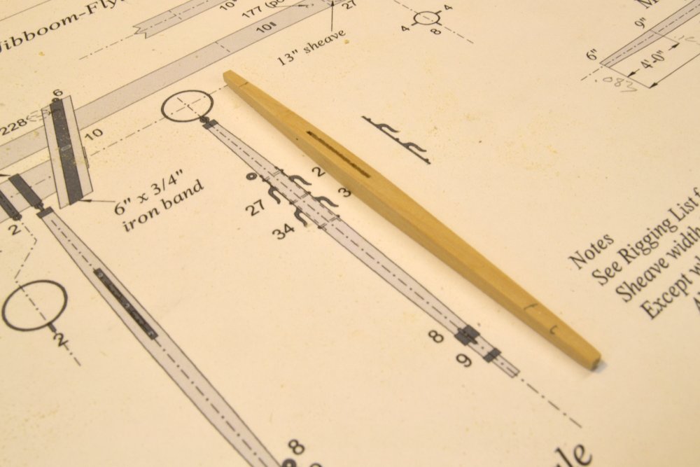
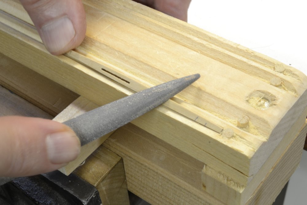
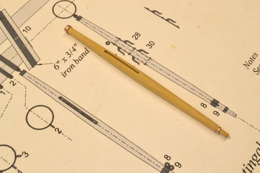
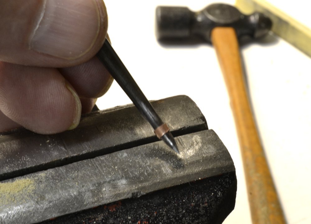
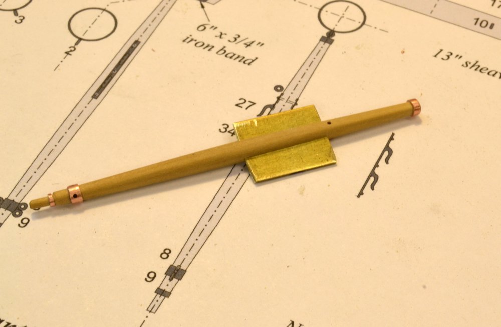
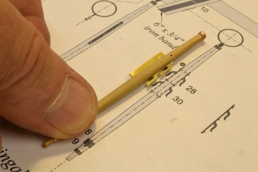
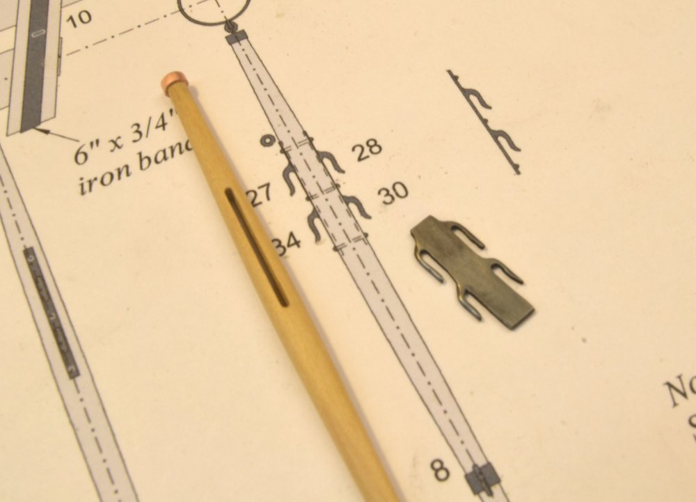
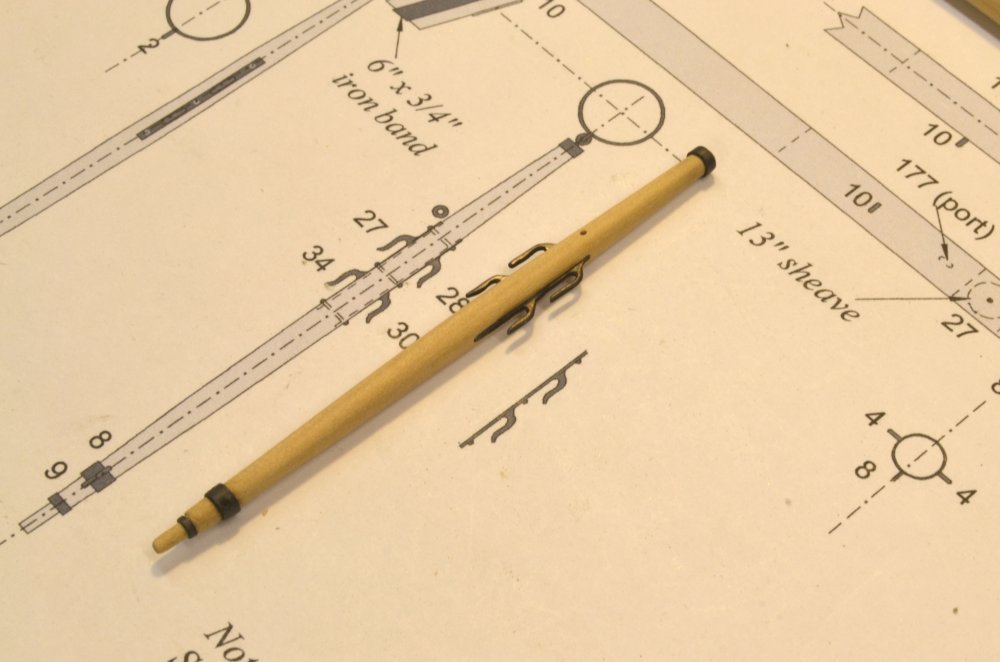
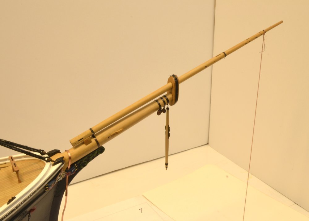
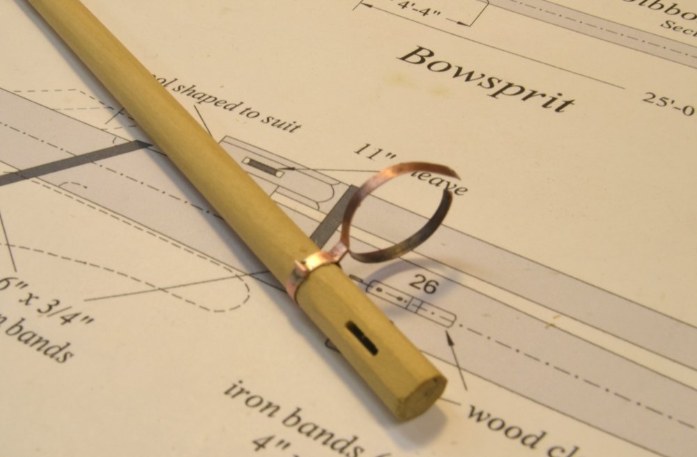
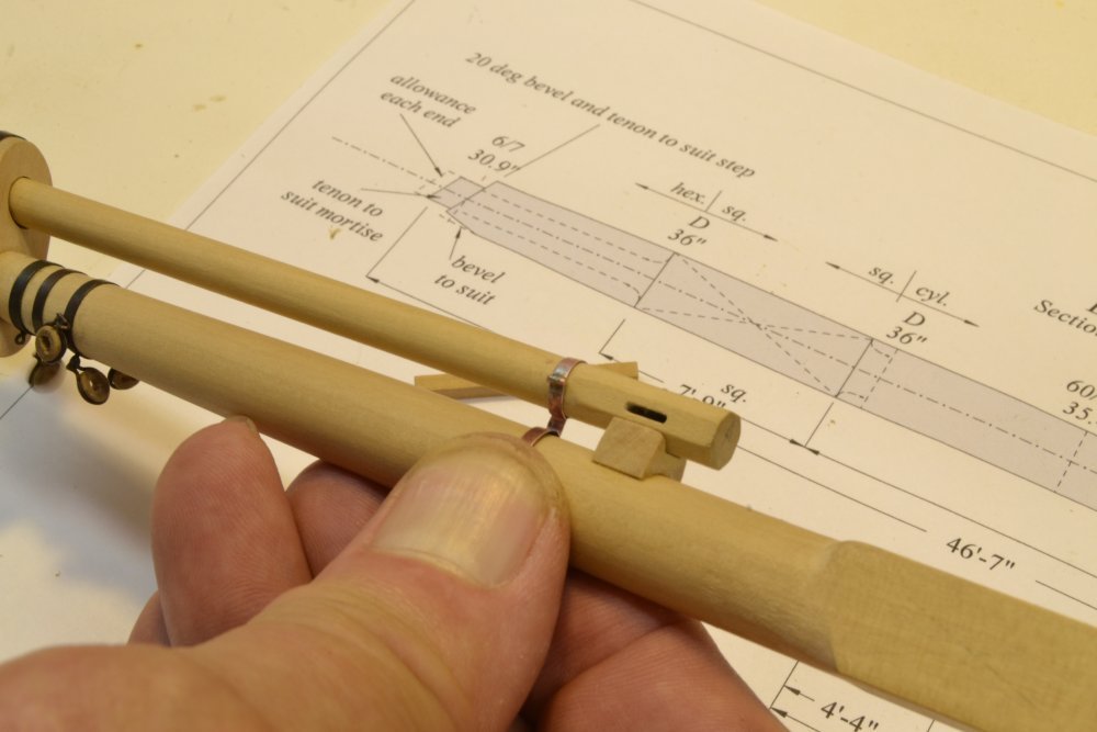
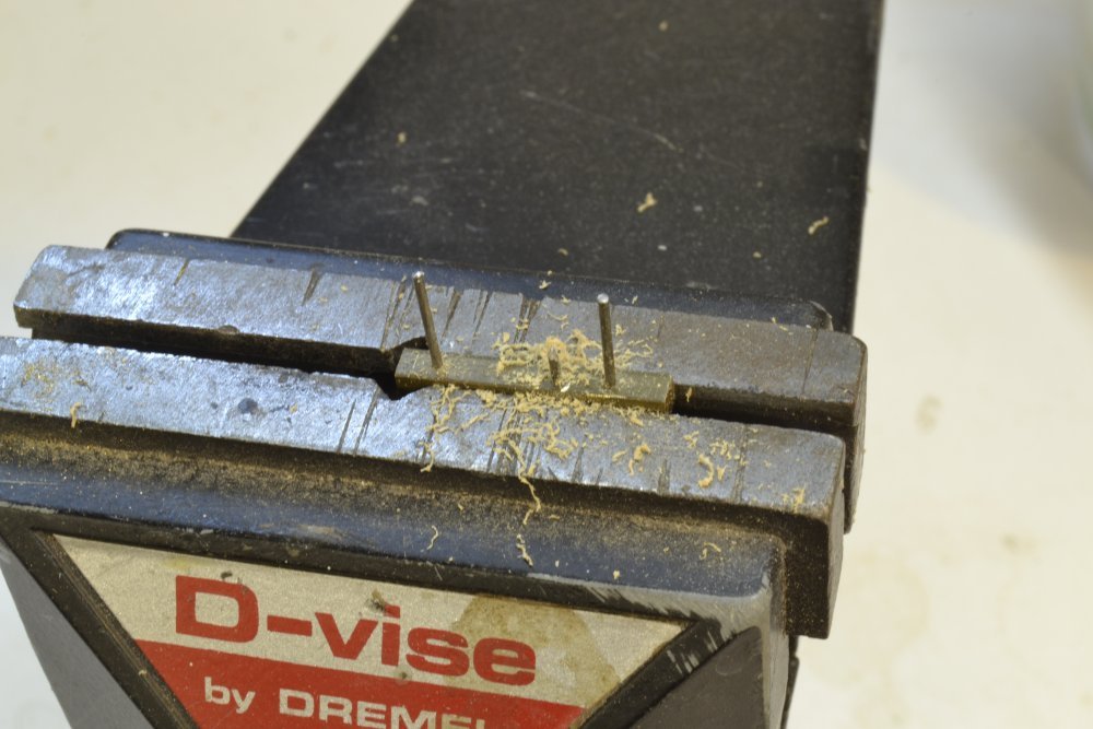
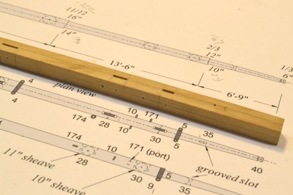
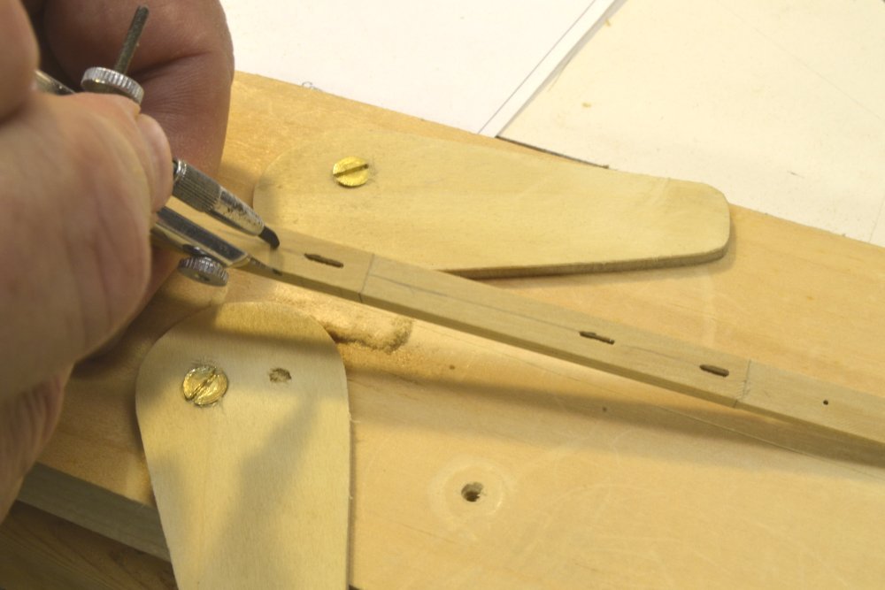
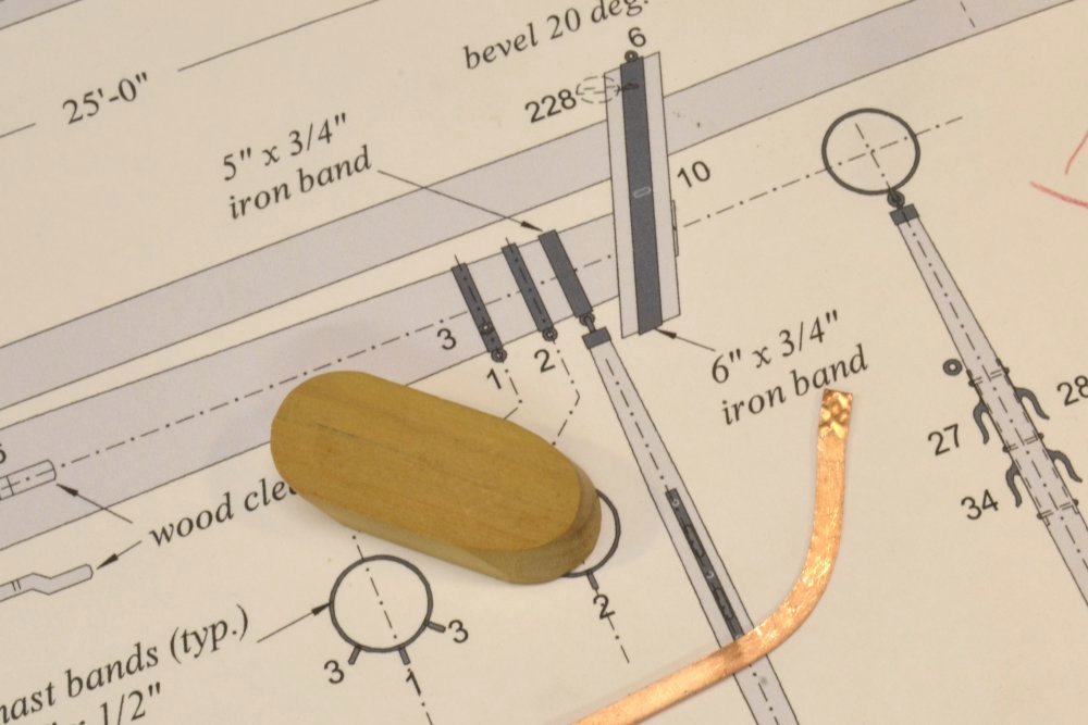
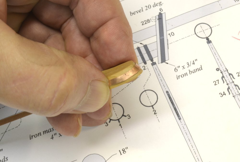
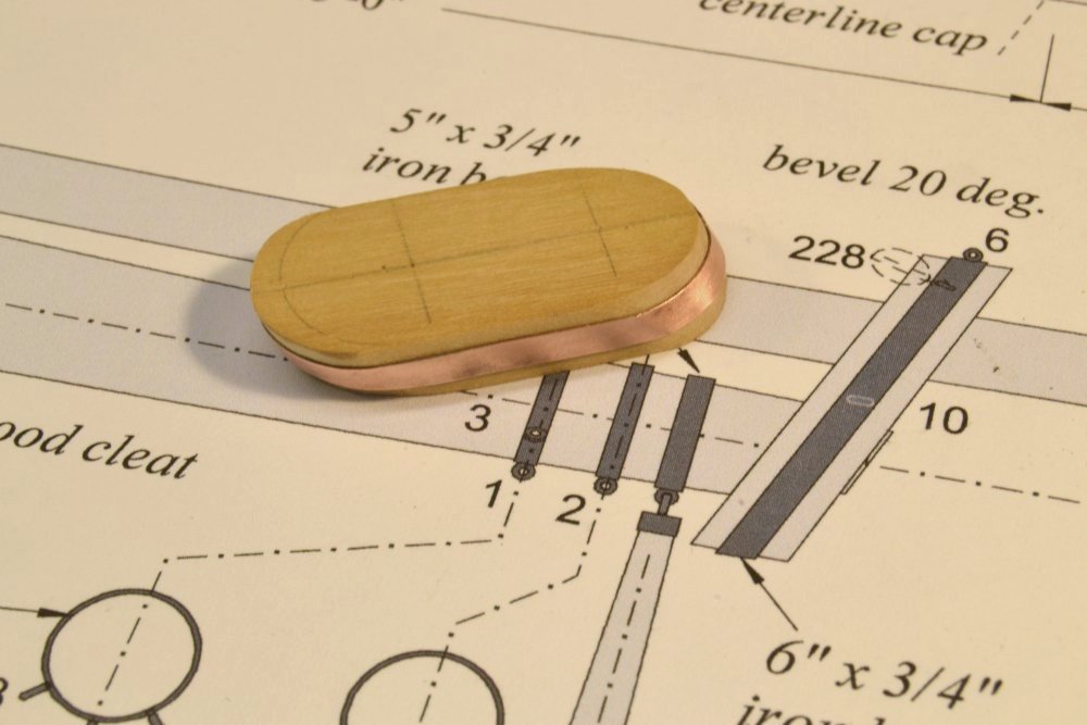
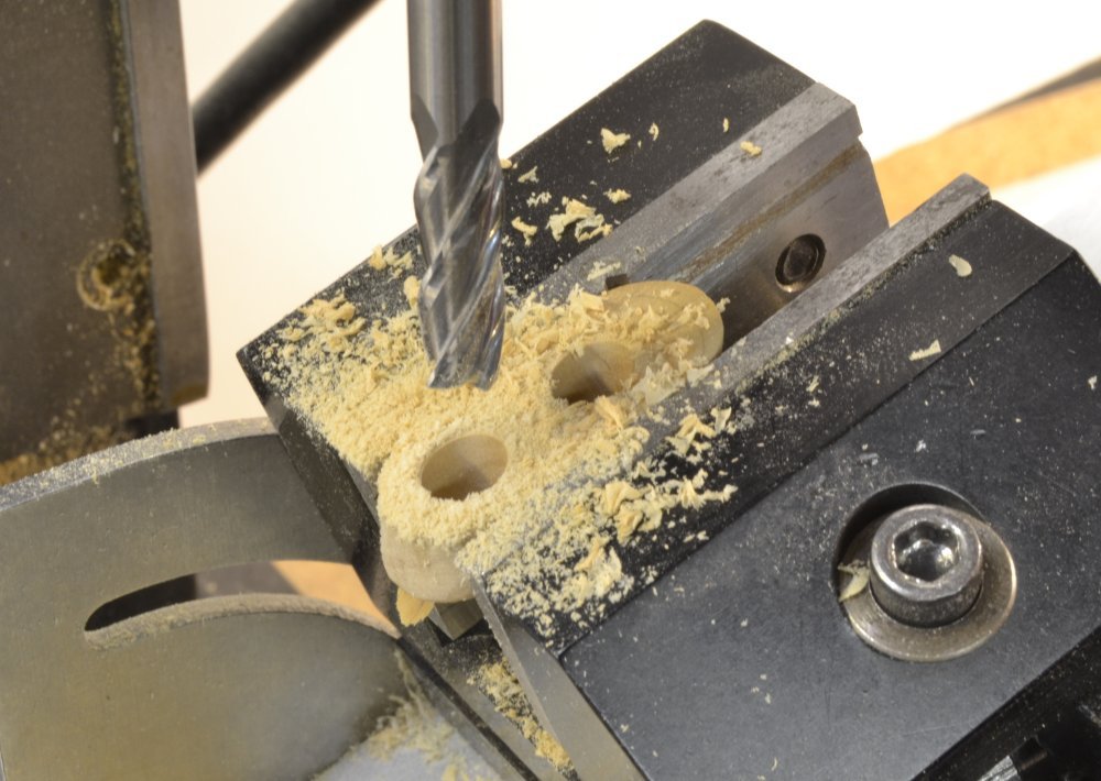
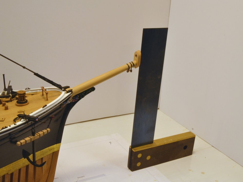
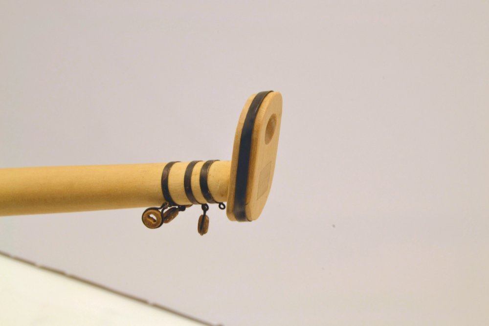
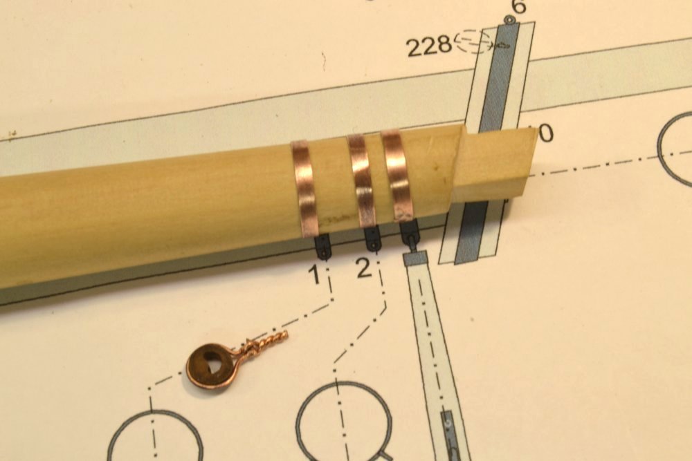
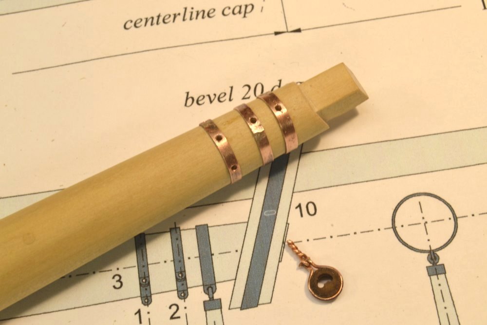
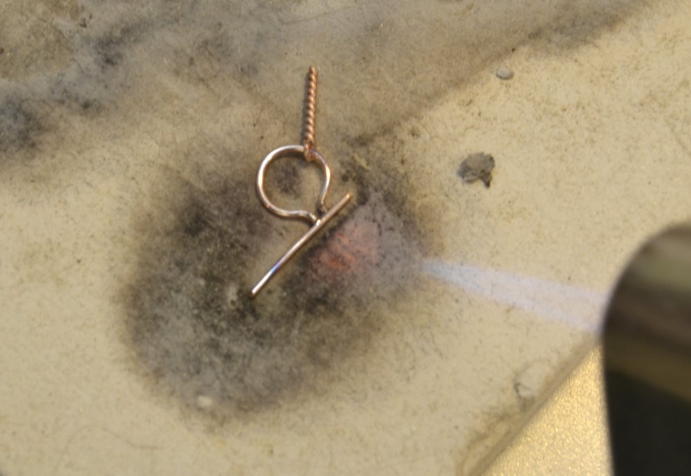
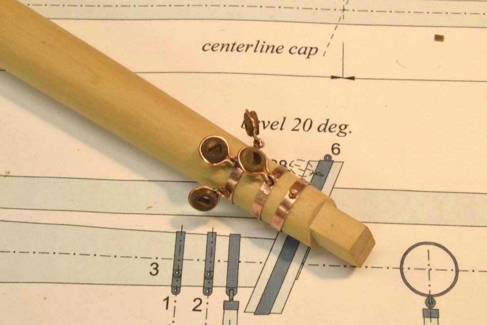
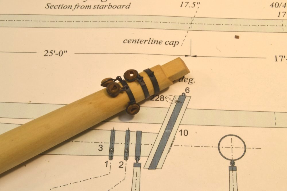
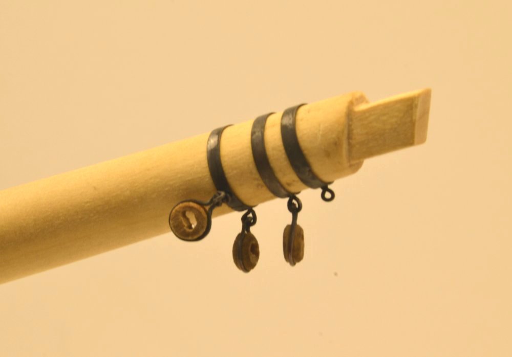
Young America - extreme clipper 1853 Part 220 – Martingale The Martingale, or dolphin striker, was a 17' long, 10" diameter spar that served as a compression member in the truss that included the bowsprit and its stays that attached to points on the hull. The stiffness provided by this assembly was critical to the support of the foremast from which various stays descended to anchor points or sheaves on the bowsprit. The "second trim" of the martingale is shown in the first picture on its drawing. The spar at this stage is a tapered square and not yet cut to length. Above the center is a slot that will receive a single plate that will be formed into the double iron cleats on either side. This slot was milled after overall sizing but before any tapering, for reasons described earlier. The next picture shows trimming the spar to an octagonal shape. On this relatively small diameter spar, this trim was done by eye, without scribing guide lines. The next picture shows the rounded spar with reinforcing bands fitted over the ends. These bands were made from copper tube, saving the fitting and soldering used on larger bands. To fit the diameters on the spar, rings cut from the tube were enlarged as needed using a center-punch as a mandrel as shown in the next picture. The rings are sized for a tight, immovable fit on the spar. The next picture shows a brass plate inserted through the slot in the spar for fitting and so that the outline of the spar could be scribed on the plate. The shapes of the cleats were then cut outside of the scribed lines with a jeweler's saw. The next picture shows an early fit check. The next picture shows the finished, blackened plate ready for final fitting into the spar. The plate was glued into the spar with CA. The next picture shows the finished spar except for its top hook. The larger ring at the bottom was drilled at this stage to accept four eyebolts that will secure two forward stays that anchor on the outer bowsprit and two backstays that anchor on the hull. These stays, like most standing rigging on the bowsprit, are chain of different sizes. The last picture shows the martingale hooked to is eyebolt behind the cap. The picture also shows iron (copper) banding for the gammoning being fitted over the lower bowsprit and under the figure boards. A length of chain is shown secured to the forward end of the jibboom during tests of different connection methods. This is not the final chain. More on the chain rigging later. Ed
- 3,618 replies
-
- 26
-
-
- young america
- clipper
- (and 1 more)
-
HMCSS Victoria 1855 by BANYAN - 1:72
EdT replied to BANYAN's topic in - Build logs for subjects built 1851 - 1900
Just catching up with this interesting project. I look forward to seeing the later phases. Ed- 1,013 replies
-
- 2
-
-
- gun dispatch vessel
- victoria
- (and 2 more)
-
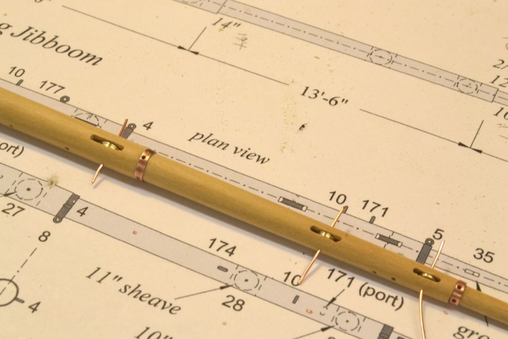
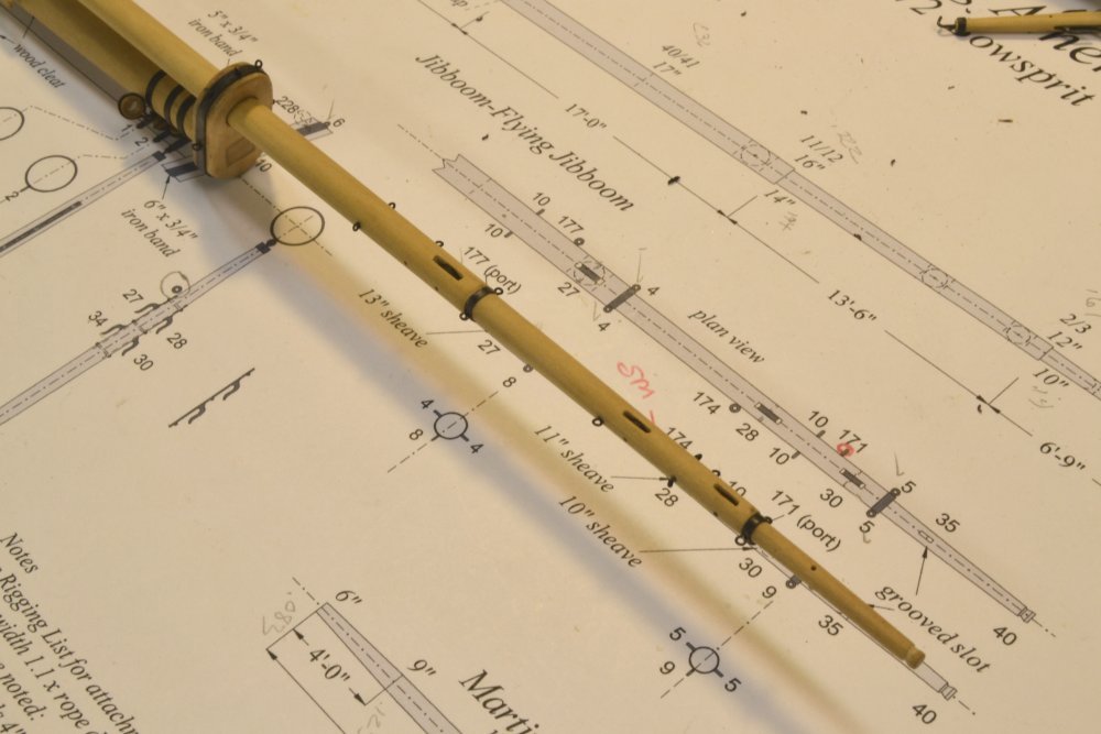
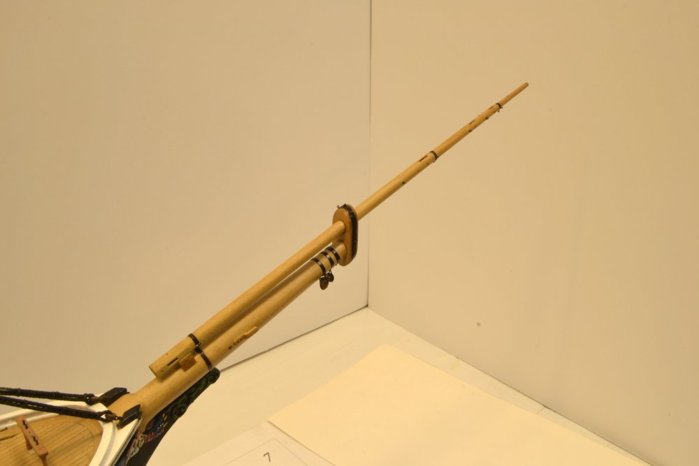
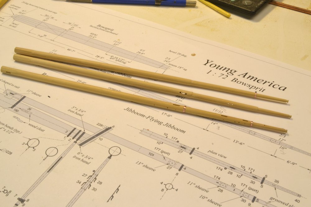
Young America - extreme clipper 1853 Part 219 – Bowsprit Assembly Before assembling the two main spars that make up the bowsprit, I wanted to get as much of the detailing done as possible while the individual spars were still easy to handle and grip. In the first picture, three of the four sheaves have been made and temporarily fitted into the Jibboom/Flying Jibboom. These were turned to the specified sizes in brass and are shown here held in place by lengths of copper wire. The picture also shows the bands on this spar drilled for eyebolts. In the next picture, the ironwork and sheaves have been blackened and permanent copper wire bolts have been driven through the spar to hold the sheaves. The picture also shows the martingale that will be covered in the next part. The next picture shows one of the wooden, fore topmast stay cleats being glued to the side of the bowsprit. The stool for the jibboom may also be seen. The jibboom is secured to the bowsprit with a hinged "bale" that surrounds the upper spar. This is connected to a larger iron band around the bowsprit. The fabricated ironwork is shown in the next picture. The next picture shows both the stool and the bale. The lower part of the bowsprit band was drilled and nailed into the bottom of the bowsprit. As will be seen in the last picture, the underside of this band is hidden over the stem billet. The next picture shows the assembly fitted out with all required eyebolts. Since none of these eyebolts are connected using soldered shackles, all could be permanently secured at this stage. The method for making these from twisted copper wire was discussed in an earlier post. The last picture shows the bowsprit temporarily fitted into the hull. This picture was taken just after finishing the assembly, including the ironwork, with a diluted solution of Tung oil. The assembly is almost ready for permanent installation. It will be held down with an iron gammoning strap just forward of the knightheads that will bolt to the stem below the figureheads. The martingale that will be suspended below the bowsprit cap will be covered in the next part. Ed
- 3,618 replies
-
- 33
-
-
- young america
- clipper
- (and 1 more)
-
I'm with Druxey on the rotary tool. Too risky for me. Have you tried a cabinet scraper? Very fast and accurate for the rough work - at the very least. Does require some prep though, to create the cutting edge. Ed
-
I no doubt saw the tool on the Dunbrody log, but I have also seen larger scale versions for sale for general woodworking. Very nice work on the bowsprit. I also like the photo of the actual bowsprit showing the shackled guy chains and the bostay chain with the turnbuckle. I look forward to your modeling of these. Ed
-
Magnificent model, Nils. I marvel at the amount of work you have put in on this and the beautiful result - and in such a short space of time. Amazing. Ed
- 2,625 replies
-
- 5
-
-
- kaiser wilhelm der grosse
- passenger steamer
- (and 1 more)
-
What you say is quite true, Carl. Understanding the accuracy limitations of any tool is always important, as is the point of diminishing returns on special tool making. I estimate that this marking tool will be useful on at least half of the sparwork on YA, but it is not a universal panacea. Ed
- 3,618 replies
-
- 4
-
-
- young america
- clipper
- (and 1 more)
-
Jerry, the wood is Castello. Carl, I made the device to be used on all the spars on the model down to the smaller practical sizes. It was used to mark the lower main mast. Much below an actual 3/16" I do this without lines. When the spar approaches 90 deg to the opening the scriber is most accurate. As the angle approaches zero, as it does with smaller spars, the diameters of the guide rods affect the accuracy. I suppose having closer guides for smaller work could help this, but I have not found the guides as useful below a certain size. Even with the scribed lines, it is important to visually check that the width of the flats on the wood are the same size. Ed
- 3,618 replies
-
- 6
-
-
- young america
- clipper
- (and 1 more)
-
I got the idea for this from a similar tool for marking centerlines that I saw somewhere. That would be another useful device. Ed
-
Hi Frank, Yes, the scriber is a pointed hard steel .032" rod that sctratches the line into the spar. Because the scratch is on the apex, it will later be remove from the rounded areas. I will probably include a drawing of this in the next book, but if you are going to make it, the scriber point needs to be 7/24th from the insides of the guide rods - not their centers. Ed
- 3,618 replies
-
- 3
-
-
- young america
- clipper
- (and 1 more)
-
Sorry, Carl. The term "spar" is generic and can refer to any mast, mast section, yard, boom, etc - at least according to the Maritime dictionaries that I am using. It is a useful term in the case of "spar-making" because the processes are similar regardless of the type of spar and "sparmakers" made all of them.. I am using the term for this reason. The spar shown in the last 2 posts is the Jibboom/Flying Jibboom. It is a single stick combination of the two, hence the combined term. The bowsprit is the larger base spar on which the Jibboom rests, but also can refer to the entire assembly. This is analogous to the fore mast, fore topmast, etc. where the term fore mast refers to both the lower part as well as the total mast assembly - or to one of my favorites where "coamings" may refer to either the total hatch framing or just the fore and aft members.. Hope this helps. Ed
- 3,618 replies
-
- 9
-
-
- young america
- clipper
- (and 1 more)
-
Great work, Frank, as usual - and an interesting way to mark out the octagonal apices. Whether its my worsening eyesight, increasingly unsteady hands, or whatever, I find it harder and harder to make and use pencil lines on wood. Ed
-
Beautiful, clean woodwork, Mike. Ed
-
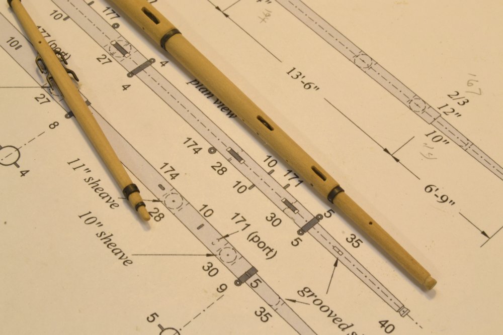
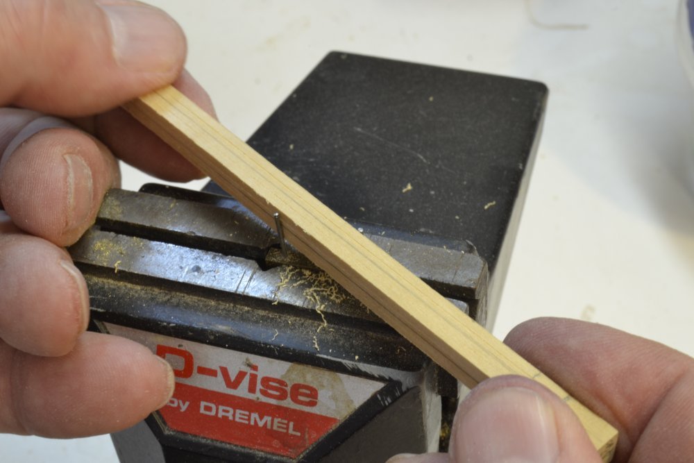
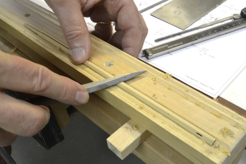
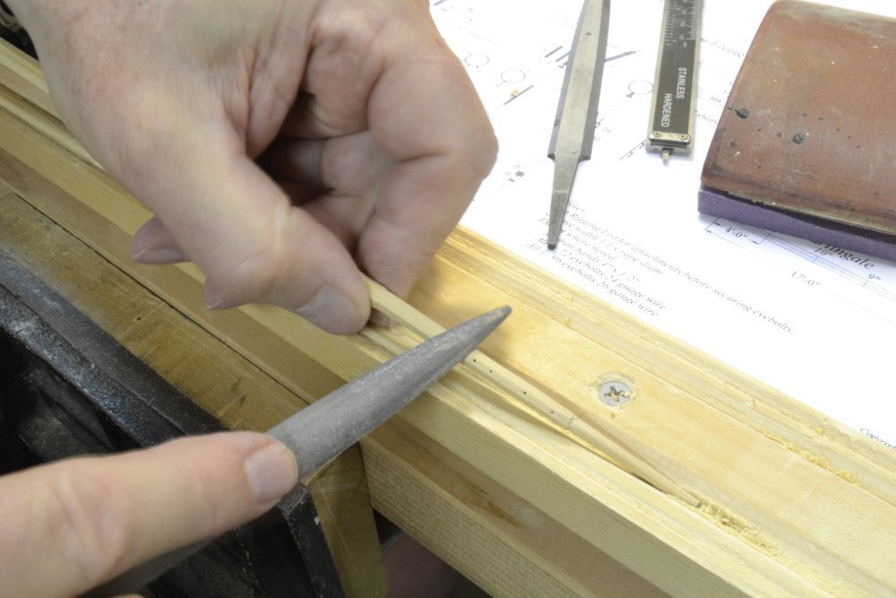
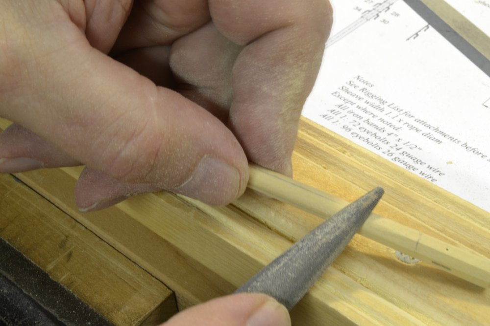
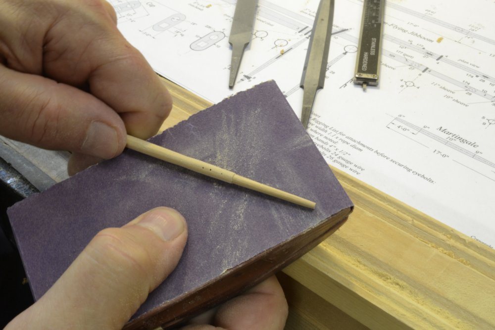
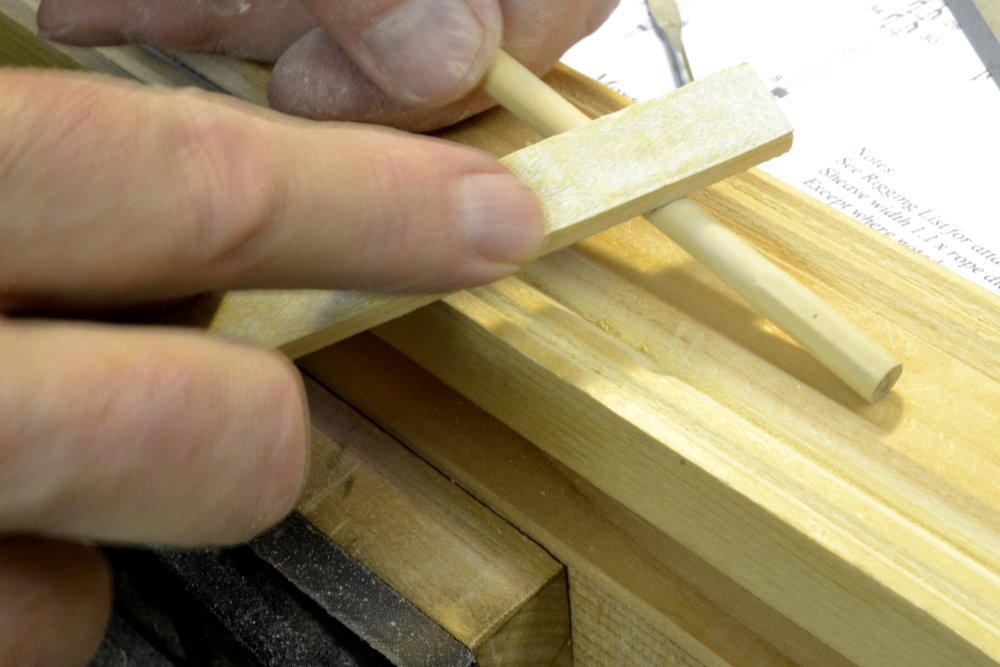
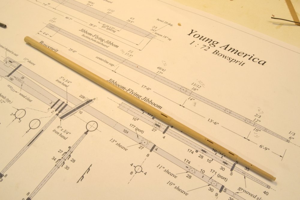
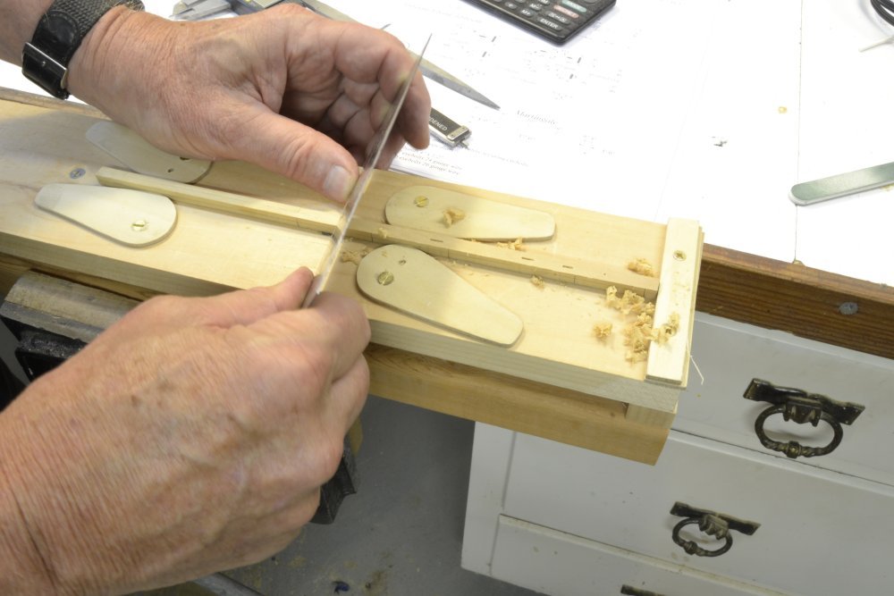
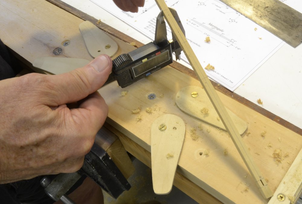
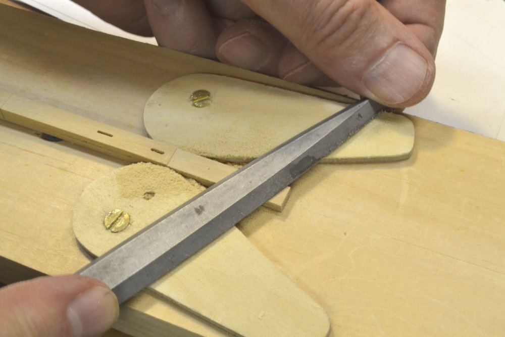
Young America - extreme clipper 1853 Part 218 – Jibboom/Flying Jibboom 2 In the last part the spar was reduced to the "third trim" – square in section but tapered to almost the final sizes along the length. The next step is to convert the square into a regular hexagon with the reduced diameters along the length. To mark the apices of the octagon on the four sides of the square I used the small device shown in the first picture. This has two guide rods with a scriber set between them at precisely 7/24 of the guide spacing from one of the guides. This corresponds to the location of the octagonal apex on the initial square. The center of the scriber is set at that distance from the inside of the guide bar. The hole spacing for these rods required some calculations and precise setup. The next picture shows the tool in use scribing an apex line on the squared spar. This method was used on the larger parts of the spar. The spar is drawn over the scriber while keeping the sides in contact with the guides. The scribed line will then be made along the octagonal apex regardless of the spar taper. I have found the accuracy of this method to be quite adequate on sections a small as 1/8" diameter. Since the scribed lines are on the apices, they will eventually be filed off during rounding. In the next picture the initial shaping was done with the cabinet scraper and is being finished with the file as shown. The scribed lines are an initial guide. The final sizing along the spar is done by progressive checking with the calipers at the key points and visually making sure the width of the octagonal sides are equal. In the next picture, a file is being used to shape the octagonal faces on the smaller part of the spar without scribed lines – using the calipers and visual inspection. When the correctly sized octagonal shape is produced along the spar, it is ready for the final rounding. If there are radial holes perpendicular to the new sides of the octagon, these should be bored before proceeding with the final rounding. This rounding is being done at the lower end of the spar with a fine file in the next picture. This begins with filing off of the octagonal apices, then further rounding. During the initial rounding the scribed pencil lines from earlier steps will remain visible as guides. These will be removed as the spar is reduced to its final diameters in these last steps. In the next picture the final-sized round shape is being sanded with a 200-grit sanding block using emove remaining corners and to obtain final dimensions. I started this final shaping at the small end and completed each section before moving on – again with frequent diameter checks. In the next picture a sanding stick is being used for final smoothing and shaping at the round-octagonal transition near the lower end. The completely shaped spar is shown in the last picture. Fine abrasive sticks were used to produce the final finish. Also, the end of the spar has been shaped to hold the skysail stay at its very tip. The spar is now ready for its iron bands and sheaves. Ed
- 3,618 replies
-
- 25
-
-
- young america
- clipper
- (and 1 more)
-
Thank you for these comments and the many likes - and I always like questions - even if I may lack the answers. Pat, the file is a 0 cut Grobet full-size barrette file. I also used a fine cut similar version on the spar. Here is a link to the first: https://contenti.com/jewelers-metal-files/full-size-metal-files/grobet-barrette-files Thank you very much, Frank. I wish some of this were as routine as it may appear in the posts. The spar shown above was the third attempt. The first was slightly small - causing me to start anew with the slight excess measured above then remove it in the last sanding steps. The second was "perfect" until I started cutting the sheave holes - hence the decision to do that work first on the square. So, as I am sure you know, processes evolve slowly sometimes, and I am learning like everyone else. Few of us can can comfortably repeat processes well learned over many previous builds. I am glad if others get some benefit from what I learn along the way. Just for fun, here is proof of this particular learning experience: Ed
- 3,618 replies
-
- 21
-
-
- young america
- clipper
- (and 1 more)
-
Thanks for the comments and likes. just a quick couple of comments. Steve, the mill is not essential and the work shown could be done with a drill press, taking care to center mark the work accurately before boring. Micheal, welcome back. We had some dialog on this earlier after similar comments. I know these look small but they are quite substantial ~2" diameter iron eyes and shackles. Having the same initial concern, my recollection is that these calculated out at a number of times stronger than the stays. With reinforcing plates under the beams, I believe these wood be very strong. Ed
- 3,618 replies
-
- 6
-
-
- young america
- clipper
- (and 1 more)
-
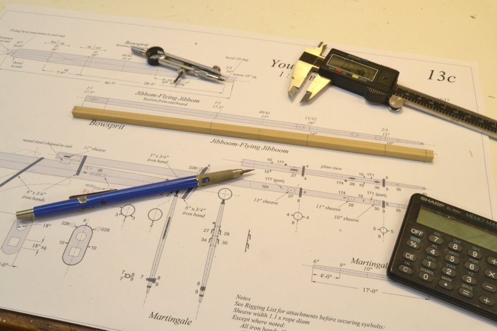
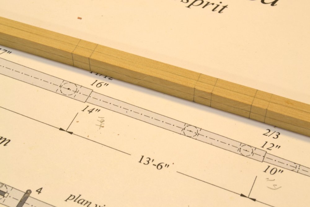
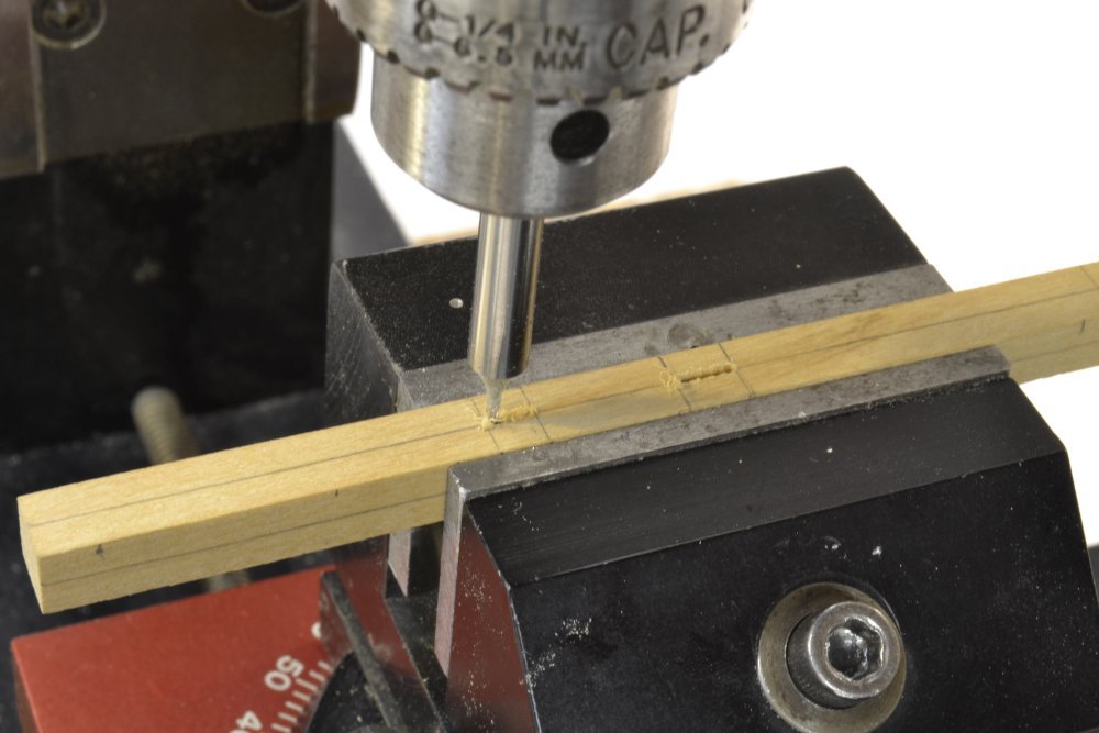
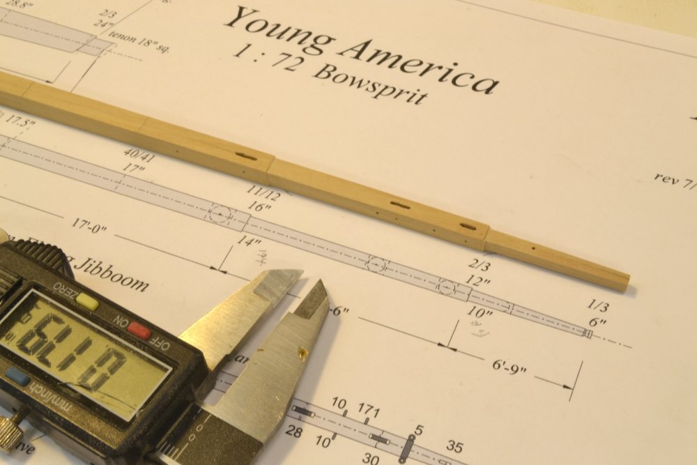
Young America - extreme clipper 1853 Part 217 – Jibboom/Flying Jibboom Thanks, everyone, for the comments and likes on the last post. Although the Jibboom and its integral Flying Jibboom may be added after the lower bowsprit is permanently in place, I believe it is preferable to complete the entire assembly before securing it in the hull, so the next step is to make that spar. As spars go, this one is fairly complex. It has two steps down in diameter and is mortised for four large sheaves. One at the foot is horizontal and used to haul the spar out. The other three take the inner, outer, and flying jib (fore topgallant) stays. There is a dummy sheave for the fore royal stay and the end of the spar is shaped to secure the fore skysail stay. The lower end of the spar is octagonal. The process closely follows practice used to shape actual spars. The first picture shows step one – sometimes called the "first trim." The length of Castello shown has been squared to about 10-thousandths of an inch over the maximum cross-section of 17.5" (.236" at 1:72). Measurement points along the spar have been marked on all four faces, actual dimensions calculated for the specified full size diameters, and centerlines drawn down each face. This would be the normal starting point for shaping the spar. However, before starting that process, I machined all the mortises and bored all the radial holes – sheave slots, axle holes, eyebolt holes, etc. There are two reasons for this: First, securing and centering the piece for boring/milling is much easier and accurate before it has been tapered or rounded. Also, drilling into a flat horizontal surface is easier and more accurate than drilling into a curved surface – especially if the cut is all the way through and you want the opposite location to be correct. The next picture shows the first trim marked for the locations of the stay sheaves. I used the mill for all this work. First, the vise was indicated to align it. Then, an edge finder was used to locate the stationary jaw of the vise accurately. The vise was then moved so the edge of the jaw was on the spindle center, then adjusted back by half the measured, actual width of the piece to place the spindle precisely over the center of the spar. The pencil lines on the spar thus become superfluous and the holes will be accurately centered. In the next picture two sheave slots are being milled using a 1/32" milling bit. This size bit is smaller than the smallest sheave slot. Later, the through slots will be filed out to the required size. This step centers them only, avoiding the need for y-direction adjustments, losing the accurate center, and the attendant necessary calculations. Because of the shortness of the bit, milling from both sides was needed. The next picture shows the forward end of the spar with the mortises and the other holes bored. The first shaping step is shown in the next picture. The jig is designed to hold rectangular work of varying width. A cabinet scraper was used to rough-taper the upper and lower faces of the spar. This process involves taking numerous measurements at the points along the spar, as shown in the next picture. The top and bottom faces are worked concurrently, allowing visual checking of the symmetry of the tapering vs. the marked center lines. As the final diameters are approached, finer work was done with flat files as shown in the next picture. In this picture the outermost step has been filed before working the end of the spar. Only the top and bottom faces are tapered at this stage, eventually reaching the "second trim" – two opposite faces tapered to (almost) final size. Again, at this stage I left a total of about 10/1000ths of an inch excess at each point. In the next picture the spar is being marked on the tapered faces to allow the two remaining parallel faces to be reduced symmetrically. The remaining two faces are then reduced by the same process, yielding the "third trim" of the spar shown in the next picture. This piece will next be converted to octagonal shapes consistent in size with the square profiles in the picture. Next post. Ed
- 3,618 replies
-
- 32
-
-
- young america
- clipper
- (and 1 more)
-
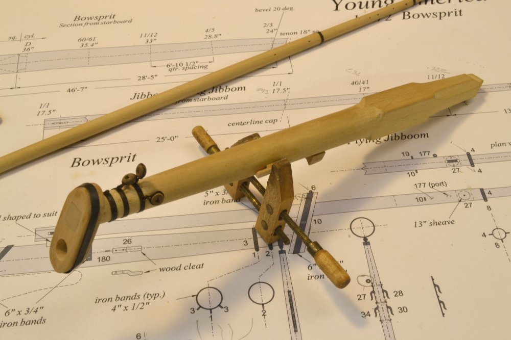
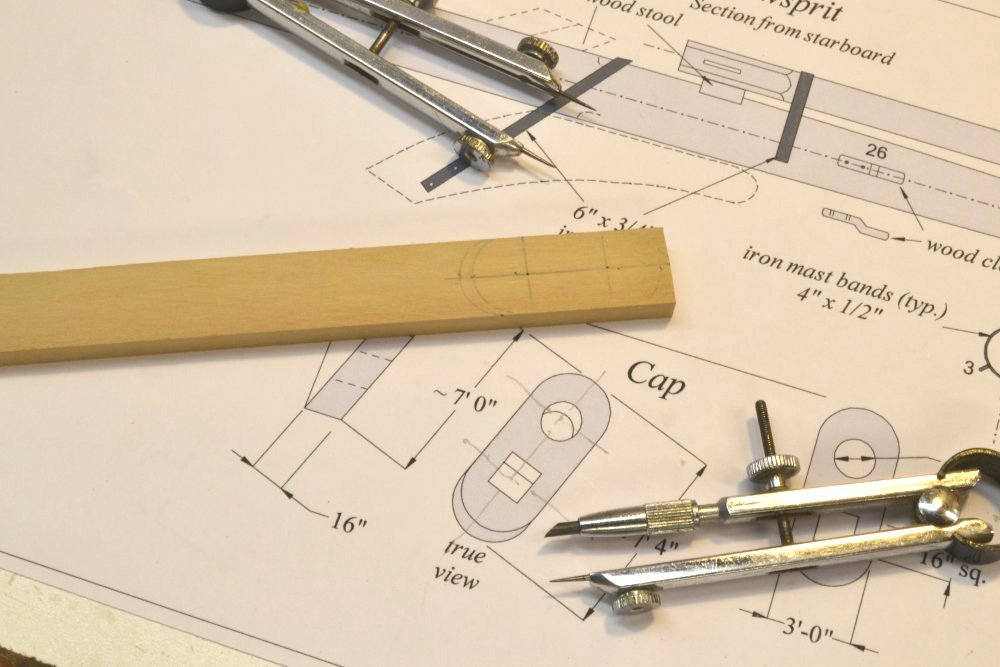
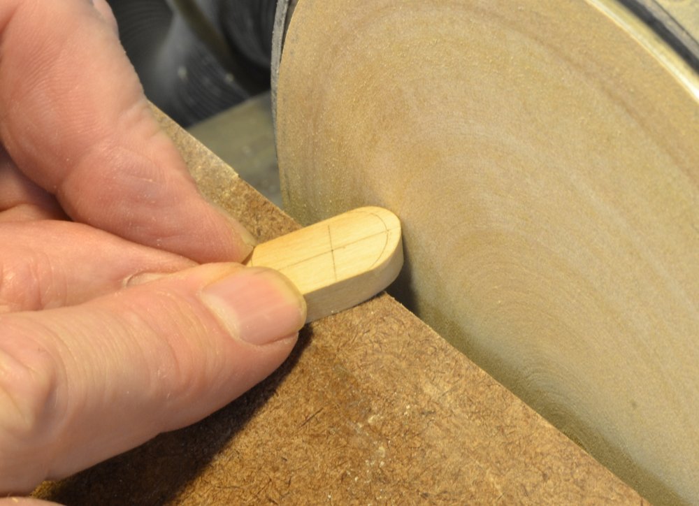
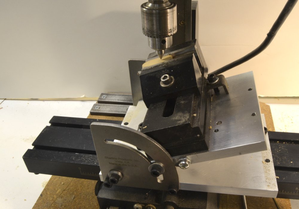
Young America - extreme clipper 1853 Part 216 – Bowsprit Cap The bowsprit cap is a heavy balk of timber that is mortised on to the end of the bowsprit to support the jibboom. It sits vertically, so the mortise for the bowsprit tenon and the round opening for the jibboom must be cut through the cap at a 20 degree angle corresponding to the angle of the bowsprit. But first the cap must be cut out and the angles of the top and bottom faces shaped. In the first picture, the outer lines of the shape and the centers of the openings have been laid out on a Castello plank, Some additional work, permanent center lines for the openings, for example, is required on the drawing shown in the picture. Once the overall piece was cut and the rounded ends shaped square on the sander, the beveled ends were sanded off as shown in the next picture. This was done with the sander table angled at 20 degrees. Some hand shaping is required where the straight side meets the curve of the ends to avoid under cutting the straight sides. The angle of the bevel varies from 20 degrees at the apex to 90 at the side. The cap is surrounded by an iron reinforcing band. To fit the shape, this must be curved as shown below, so it will lay tightly on the cap when fitted. The band may be seen on the drawing. The copper strip shown in the picture was bent progressively with pliers to the shape shown. It was then test fitted as shown below, curved for the other end of the cap, and further adjusted until a good fit was achieved. After fitting, the band was soldered to form a ring and fit over the cap as shown below. The band was then set aside so openings in the cap could be bored using a milling bit. The mill setup I used is shown in the next picture. A dead center has been mounted in the drill chuck to center it over one of the center marks on the piece. This was done before boring each of the two holes. Two 18" holes were then bored as shown in the next picture. The ¼" milling bit scales to 18" at 1:72. A 3/16" bit would be used at the 1:96 scale. After boring, the lower hole was filed to a square mortise to fit the bowsprit tenon. After fitting the tenon, the cap was set up for gluing as shown below. The square was used to check the vertical face and the side of the cap when it was glued. The last picture shows the iron band fitted to the cap and blackened. The band was secured using some thin CA, but will be well anchored in position when the rigging eyebolts are added through drilled holes into the cap. Ed
- 3,618 replies
-
- 42
-
-
- young america
- clipper
- (and 1 more)
-
Young America - extreme clipper 1853 Part 215 – Bowsprit Hearts 2 Making hearts for the bowsprit rigging was discussed in the last post. Eight of these are required to lash the chain bobstays and bowsprit shrouds near the end of the bowsprit. Bands for these connections and for the martingale are shown in the first picture. I expect to use eyes on all spar bands vs. lugs. Maneuvering shackles over lugs is a problem and contemporary documents show both. Lugs shown on this drawing will be corrected. The numbers on the drawing are the rigging line numbers at connection points. The inner bobstay is the number 1 line on the list and its eye is shown on the third band. The picture also shows a shackled heart assembly. In the next picture the bands have been drilled for the shackle eyebolts. My plan is to screw these twisted-wire eyebolts into the holes and if possible eliminate glue. This allows the full assembly to be blackened after installation without fear of unblackened glue spots. More on this below. The next picture shows a shackle bolt being soldered on with the eyebolt pre-fitted. After soldering and trimming of the bolt, the eyebolt must be slid around the ring to fit over the short bolt at the bottom. This can be a tight squeeze. The next picture shows the four shackled hearts mounted on the bowsprit. These were all twisted (screwed) into the drilled holes. They are very secure without glue, but any loose bolts can always be reinforced with glue later if necessary. This really simplifies the blackening process. The blackened assembly is shown below. This spar is unfinished at this stage so the wood has no protection yet. The ironwork was blackened by brushing with liver of sulfur solution and rinsing immediately under a faucet, repeating the steps until all the copper was black. This keeps excess black from being deposited on the wood. The spar is still damp in this picture. The last picture shows the finished assembly on the temporarily mounted bowsprit. Other work on the bowsprit may now proceed. Ed
- 3,618 replies
-
- 31
-
-
- young america
- clipper
- (and 1 more)
-
Beautiful work, Gary, but that precarious pose on the rail is making me nervous. I appreciate your words on the quality discussion in my book (books, actually) and I am glad if it has helped you. Also, many of the ideas in the book came after I had gone astray and thought about how to avoid it. And also, when you find a way to keep tools organized on the bench, I'd love to learn about it. I feel like my tools and materials are pretty well organized whenn they are put away, but once work starts.... Ed
-
Wow! A lot of pictures, Frank. She is looking lovely. You may have cornered the market on those spring clamps. Ed