


EdT
-
Posts
2,214 -
Joined
-
Last visited
Content Type
Profiles
Forums
Gallery
Events
Everything posted by EdT
-
Nice work on the figure, Frank. I've found that with small scale caervings/sculptures proportion is more important than duplicating detail. The eagle looks perfect. Ed
-
Thanks for the responses, guys. Druxey, the old guys did us a lot of favors. However, with the advent of double topsails and higher masts on clippers, some topmasts could not be slanted enough under the top and did require scuttles - at least that is what I have read. Also, of interest, is that the lower yard would have to be removed, although some trusses seem to have been designed to allow the topmast to slide through the yoke - but then the height and angle would be even more of a problem. I am glad that the YA mast lengths (at least the originals that I am using) did not cause this problem. Maury, the staves are permanent and, as I mentioned, are visible pretty clearly in the two photos of the ship. I have not found much useful data on material or size however. My guess would be wood. Ed
- 3,618 replies
-
- 5
-

-
- young america
- clipper
- (and 1 more)
-
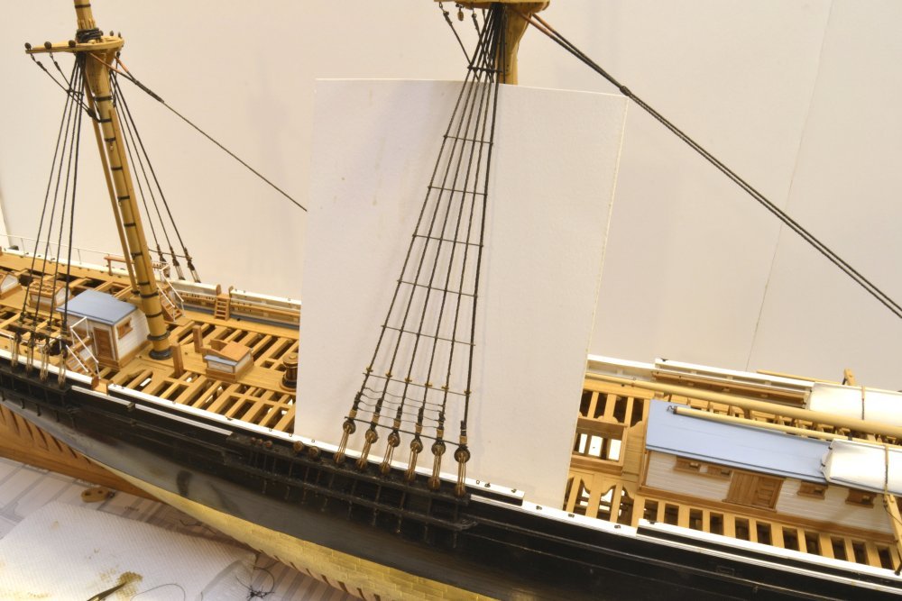
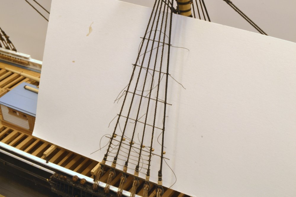
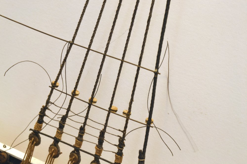
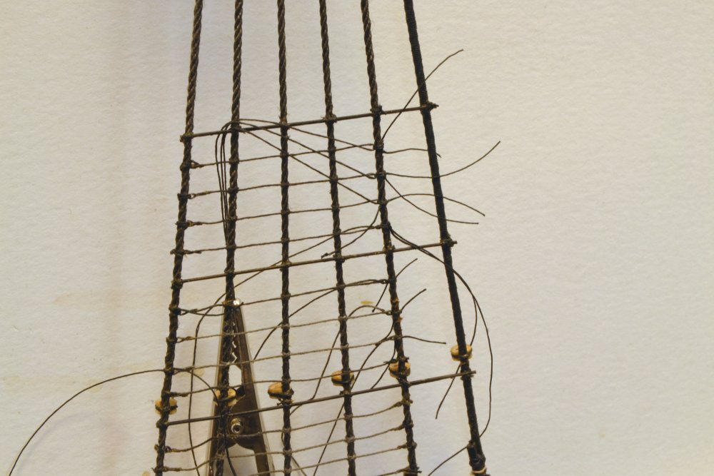
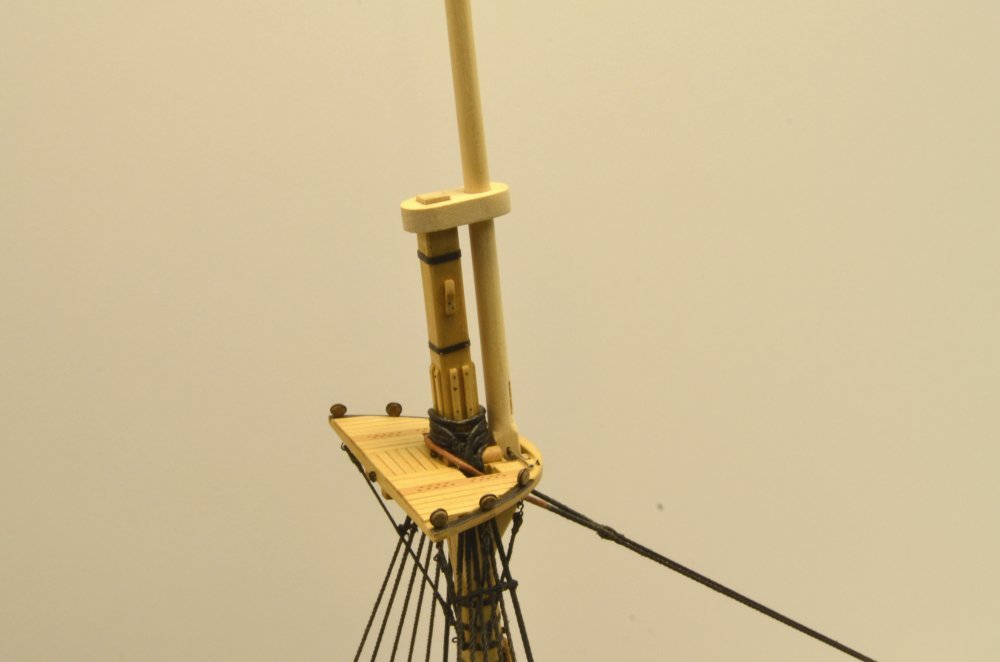
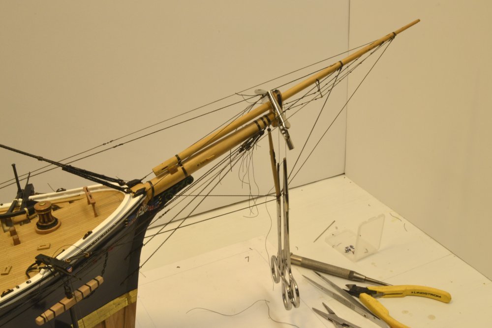
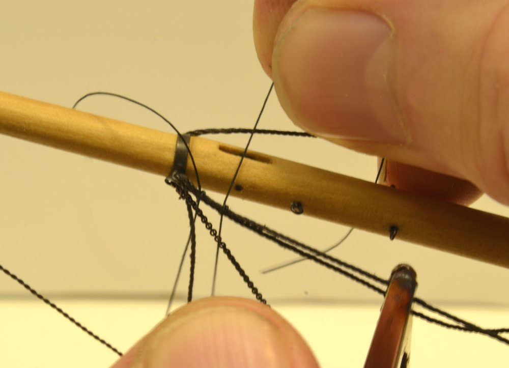
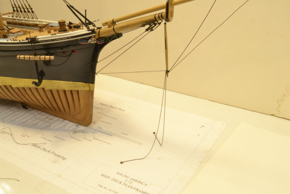
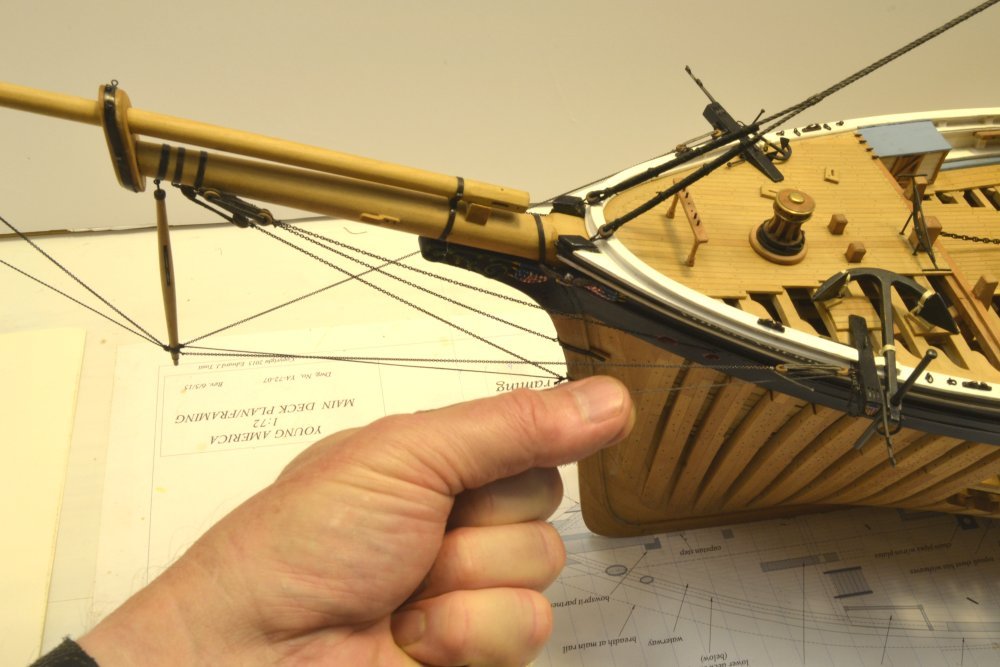
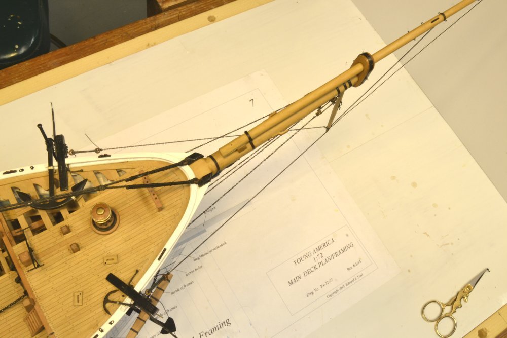
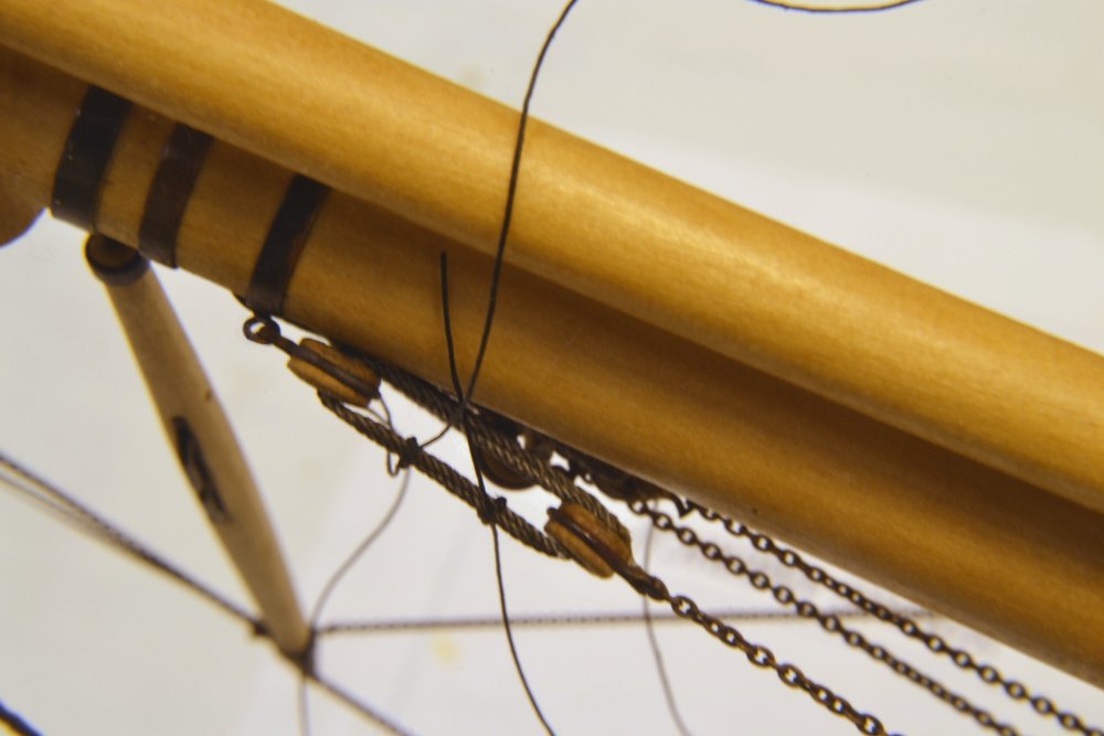
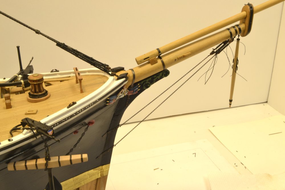
Young America - extreme clipper 1853 Part 228 – Ratlines 2 While focusing mainly on the foretopmast after the bowsprit work, I have been taking "recreational" time outs to work on that favorite task of "rattling down". I showed pictures in an earlier post of making up ratlines with their end eye splices and some of these lashed on to the shrouds. The actual production work of installing ratlines has now begun. It begins with the making and fitting of staves at intervals up the shrouds. These are shown on the main mast in the first picture. These staves are very prominent in one of the photos of the ship, spaced after every fourth shroud and extending over the full gang of six. The ratlines span only the shrouds aft of the first. The staves maintain spacing between shrouds. On the model they help maintain this spacing and the straightness of the shrouds when tying off the ratlines. The heights of the staves permit four ratlines spaced at 13" to be placed between them. The next picture shows foremast staves partially lashed to the shrouds. The sheer poles just above the deadeyes were served iron rods, 1" in diameter. The staves were more likely wood, but since they would have been tarred, the model material does not really matter. I made these of bamboo, drawn down to under 1½" diameter stained black with India ink. As may be seen in the photos, the .020" bamboo rods are quite stiff and straight, much more rigid than wire. The next picture shows a closer view of the stave/shroud lashings. After tying, the lashing are wetted with diluted, darkened PVA glue. The purpose of the glue is only to secure the knots and keep them from loosening. PVA glue has the advantage of being easily softened with isopropanol if lashings need to be removed. After the glue has completely dried, the loose ends were carefully cut off using a surgical scalpel. The next picture shows ratlines lashed between the staves. The 1½" ratlines are No. 80 crocheting cotton stained black with diluted India Ink. The end splices on the left were pre-made, then lashed to the aft shroud. Clove hitches were then tied on the next three shrouds. Height spacing of the four ratlines between staves was then adjusted before applying any glue. In the top tier in the picture the lashings on the right have been tied and glued with the ratlines pulled through and suspended temporarily as shown. In the tier below each splice was made by passing the line through itself with a needle, pulled to the left, and glued. The excess line was then cut off as shown in the lowest tier in the photo. All this looks a lot better when the excess lashing ends are gone. The last picture digresses a bit, but answered one of my nagging questions. It shows the fore topmast positioned to be rigged through the top. The topmast is longer than the height of the top, raising the question of whether it required a deck scuttle to be used to position it for raising. I assumed not when framing the deck, so the positioning of the mast in this picture was a comforting relief to someone like me who worries about this stuff. As will be seen shortly, the model mast will be installed from above after fitting to the top. Ed
- 3,618 replies
-
- 26
-
-
- young america
- clipper
- (and 1 more)
-
I never thought otherwise, Maury, but I did consider doing it - and from Druxey's input it is certainly feasible, especially if you ignore the inside of the hole. Ed
- 3,618 replies
-
- 2
-
-
- young america
- clipper
- (and 1 more)
-
Thanks, Pat and kees. I'm getting the message that I should be thinking about doing the linings. Thanks for the suggestion, Pat. Ed
- 3,618 replies
-
- 3
-
-
- young america
- clipper
- (and 1 more)
-
Good idea, Druxey. Sailor, you would not like the shipping costs - especially outside the US. We all learned a lesson with Naiad II. Ed
- 3,618 replies
-
- 3
-
-
- young america
- clipper
- (and 1 more)
-
Me too, Steve. With more than 700 lines on the model, there will definitely be some challenges in putting Volume III together - balancing the space available with the how-to focus, and with an adequate description of the amazing masting and rigging of this ship. Should be fun. Ed
- 3,618 replies
-
- 3
-
-
- young america
- clipper
- (and 1 more)
-
Thanks for the comments, Druxey and Maury and to others for the likes on the last post. There is a lot of metalwork on this model, Druxey, so maybe I'm improving with practice. I am getting used to the self-igniting, refillable butane torch, but I cannot get the flame as small as on my other torch - and does the self-igniter ever work on the first try?? Still, its more convenient than lighting up my other torch each time. Also, I found a major improvement upon purchasing fresh LOS gel. This stuff definitely has a shelf life. The new stuff can be dispensed a drop at a time from its squeeze bottle - better control and less exposure to air. Maury, after wracking my brain on how to line the caps - simulating the leather lining - I finally decided the disadvantages outweighed the visual value. The lining gaps on these were about 1/2" - .007" at 1:72 - not worth it. The best thought I had about doing this was to wrap something around the mast before sliding into the hole, but I could see problems with that. Someone may wish to try it. Pat and Micheal, I never responded to your last posts. I do appreciate your comments on process descriptions in the books as well as lesser descriptions in the posts. I am always glad to hear that the book style - going into a lot of how-to detail with pictures, oriented to less experienced builders - is appreciated. My sense is that many new builders are looking for a foothold, so not taking a lot for granted in terms of skills seems appropriate. At the same time there is a some fairly complex work on some parts, and if that can be made understandable it may be valuable for even some more experienced people. My main disclaimer is that these are just descriptions of the way I am doing it and not a statement that these methods are superior to others. Personally, I find explanations of how others are doing things to be the most important aspect of MSW. Ed
- 3,618 replies
-
- 6
-
-
- young america
- clipper
- (and 1 more)
-
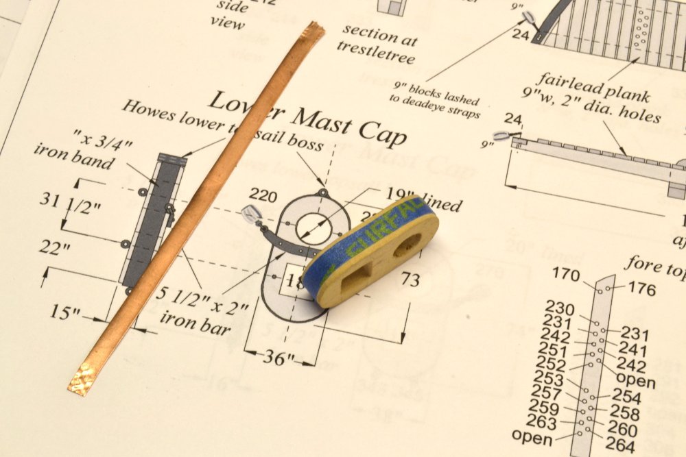
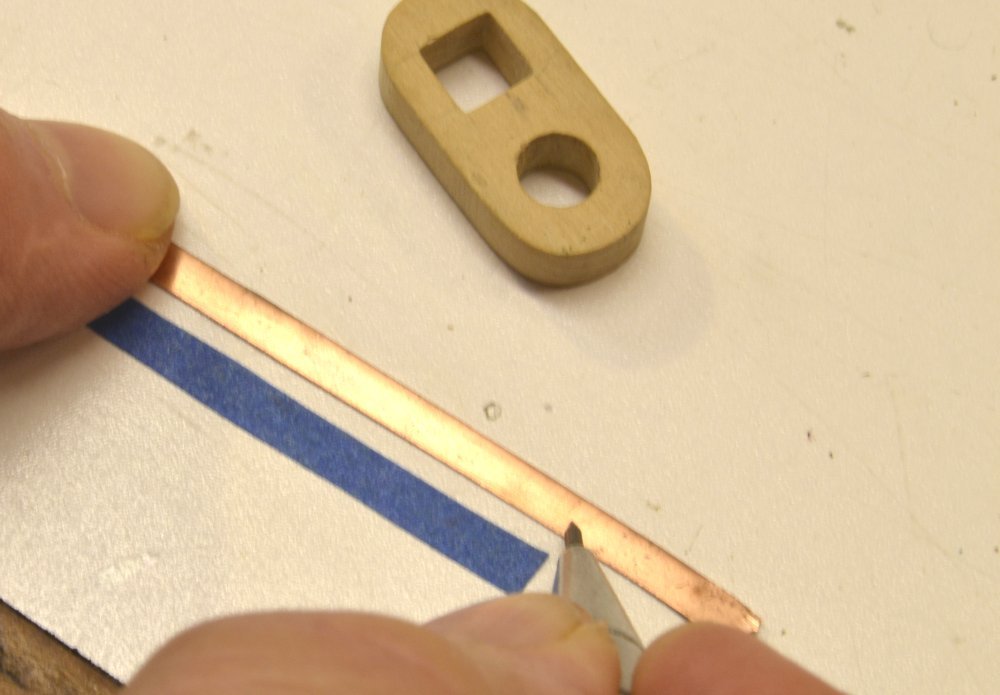
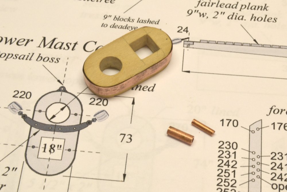
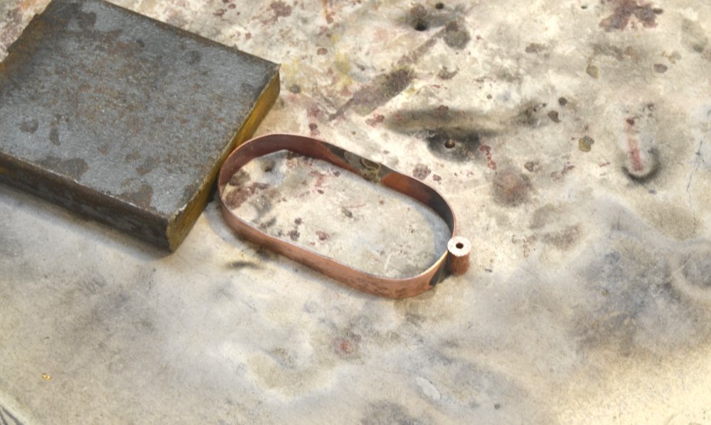
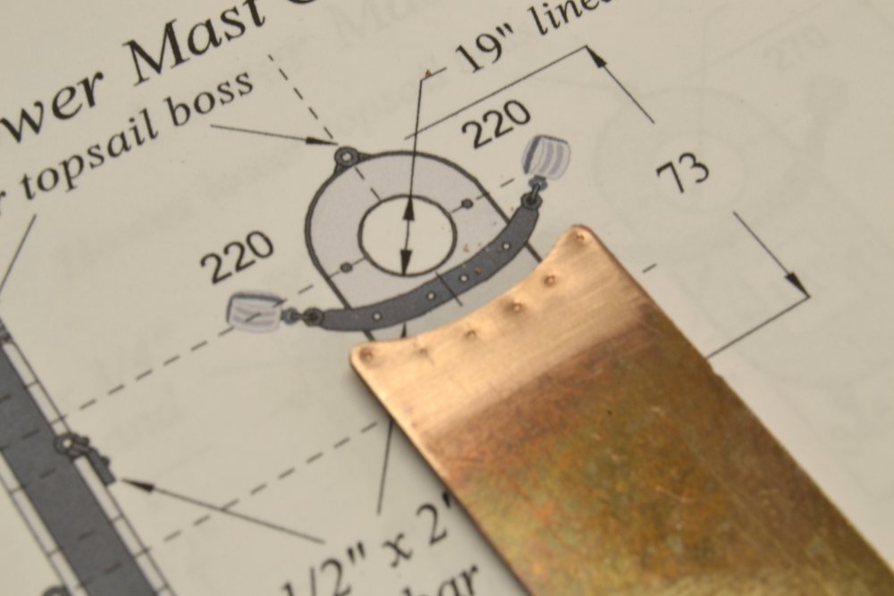
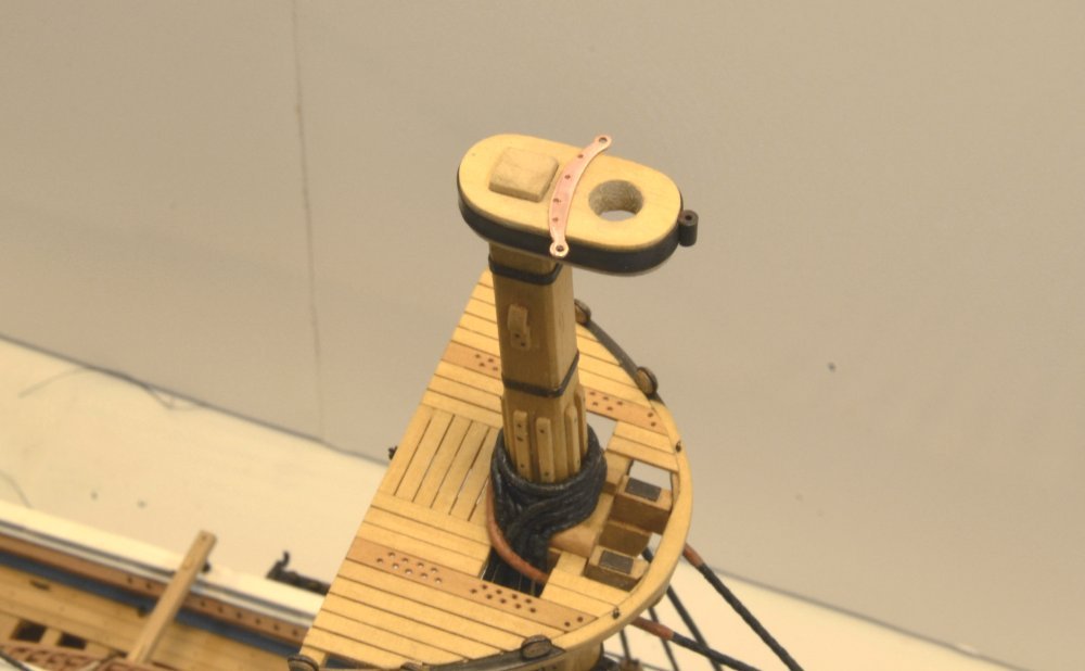
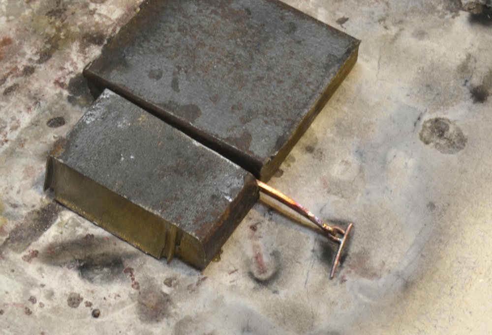
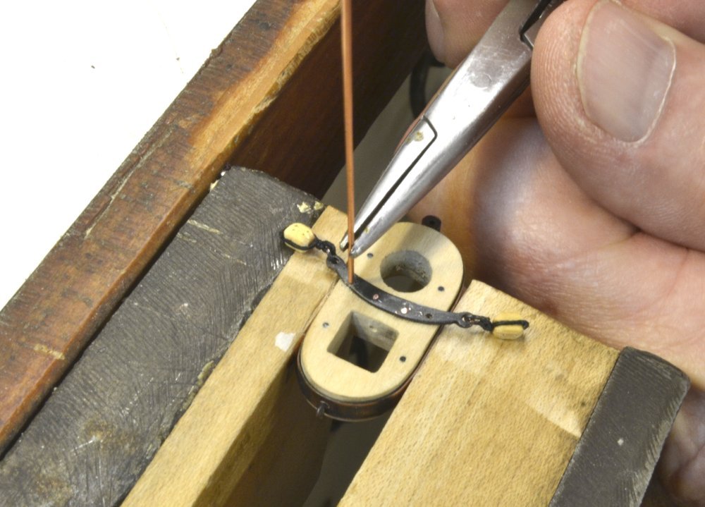
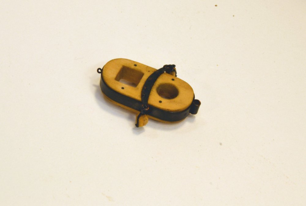
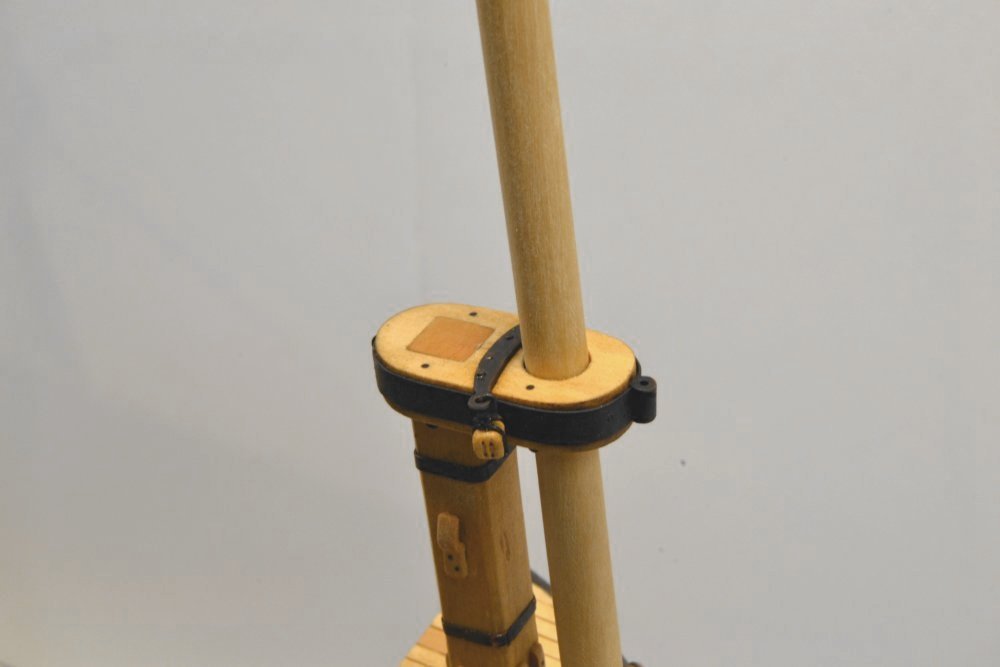
Young America - extreme clipper 1853 Part 227 – Fore Mast Cap The fore mast cap, like the bowsprit cap, was fairly easy to make because both holes in both caps were 18" square or round and this converts to a very convenient ¼" cutting tool size at 1:72 scale. The other 8 caps to be made are not so convenient. A process for making those will be described later. The wood cap shown below was first bored for the two holes, accurately spaced. The aft hole was then squared with files. The picture shows the straightened copper strip that will be used for the band around the cap. This is large and heavy because it must support the lower topsail yard Howes truss. The cap itself is shown with a strip of masking tape around it perimeter. This served as a gauge for the length of copper strip needed for the band. The tape was transferred to the bench so the copper strip could be marked out as shown in the next picture. In the next picture the band has been silver soldered to form the band and that has been fit over the cap. In the picture, two bits of telescoping copper tube are shown. These were combined and soldered to form a heavy boss that was then soldered to the forward end of the cap as shown below. The tubing boss was filed flat on one side to fit against the band as shown. The band joint may also be seen in this picture. The lower caps are each fitted with an iron bar with eyes at the ends. These support double blocks that take the lower yard topping lifts. To make this piece, the concave aft face was first filed out and the holes for the eyes and the mounting bolts center-marked as shown below. After drilling the holes, the bar was filed to its final shape and polished as shown in the next picture. This also shows the blackened cap band. The topping lift blocks will be shackled to the eyes in the bar. Again, because the shackles are soldered assemblies, this must be done before fitting the bar to the wood cap. In the next picture a shackle has been soldered at one end of the bar. With the shackle made, the blocks were fitted. It is much (very much) easier to strap and attach the blocks on the bench, so these were installed next. In the next picture, the bar is being bolted to the cap. One of the copper "bolts" is being inserted through the bar and into an undersized hole in the wood cap. These were then cut off just above the bar and riveted flat to hold the bar. Bolts through the forward end of the band were also added on either side of the boss to keep the band in place under the weight of the yard. Five eyebolts are also installed in the cap at this stage – four on the underside and one aft through the band. The bolt heads and the blackening that was scuffed during this work was then touched up with a brushing of liver of sulfur solution. The finished cap, still wet from the solution is shown below. In the last picture the cap is temporarily fitted to the masthead with the topmast. The top of the lower mast head tenon has been filed flush. Before the topmast and the cap is permanently installed further work on the mast is needed – futtock band, crosstrees, futtock shrouds, etc. -. All this must be done with the mast inserted through the cap. I omitted the 1" lining between mast and cap in favor of a tight, unglued fit for the topmast and to avoid the complication of the very thin lining. Ed
- 3,618 replies
-
- 38
-
-
- young america
- clipper
- (and 1 more)
-
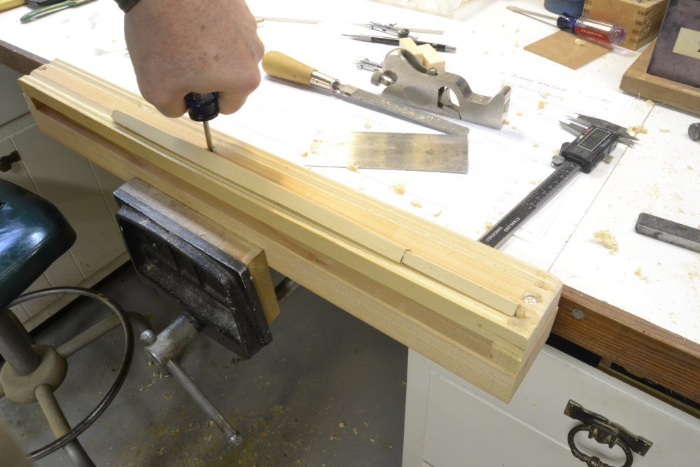
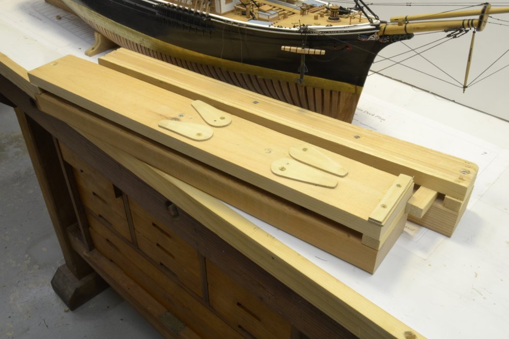
Thanks for these comments and questions. Alan, below is a picture that I think shows what you want. The grooves are simply v-grooves of a few different depths to accomodate different size of spar. Dowel stubs are inserted at the end as stops. Pat, this picture should help answer your question. I apologize for the brief cryptic explanation of the curving of the bed, so I will expand a bit. In the picture the center of the bed is being depressed by tightening one of the two screws placed on the center line of the bed for this purpose. The picture shows one of the masts. These masts have their maximum diameter at the partners and taper down in both directions in a curve. Yards are similarly curved from the center to the ends. Curving the bed of the fixture to roughly fit this curvature allows the spar to lay flat on it entire length so it does not rock when shaping. This was the purpose of elevating the bed off the base that is held in the vise. This curvature is not always needed, so to straighten the bed the screws are loosened. However, after curving, the bed takes a set, so to return it to flat, a spacer is inserted under the center. This spacer is the thickness of the end supports. Note the screws at the end of the bed. These hold down the ends when the spacer is forced in after loosening the screws. On the other fixture the cams are about 3" long with a 1 1/4" diameter at one end. The screw is offset by about 1/4". However, these are not perfect and I suggest some trial and error. Also, the cams at their tightest point should just about touch. Hope this helps. Rob, I have seen caps on some models that were parallel to the tops, i.e. horizontal, but have my doubts that many tops were made this way. This would require an angled mortise and tenon that would be difficult to make, would be much less strong, and would be more complicated to install. Crothers shows caps in his book perpendicular to the mastheads, but but shows them two different ways (??) on his YA drawing made much earlier. I have found other instances of Crothers updating his designs in the later book. Builders schematic spar plans sometimes show them horizontal. A more authoritative reference is Fincham, 1843 Mastmaking. This was a widely used source at the time and goes into extreme detail on how to make masts, etc. Fincham was one of Crothers main sources for his book. I have attached the relevant pages below. You will see that the square hole is tapered just 3/4" bottom to top on the fore and side faces only (called strengthening down) with the aft face "is square or made perpendicular through to the underside." You will find this on page 261 para 1. P 263 describes fitting the masthead tenon. I went with Fincham. Rob, I will provide an overview of making the yards and the truss in a future post and will fully describe the process, including the "made" lower fore and main yards in the book, Volume III. By the way, I have been encouraged by my publisher to mention that Volume II is available and selling well. Comments from those who have received it have been very encouraging and gratifying. Special thanks to all those happy customers. Thanks for the questions, guys. Ed Fincham mastmaking 1843 mast caps.pdf
- 3,618 replies
-
- 19
-
-
- young america
- clipper
- (and 1 more)
-
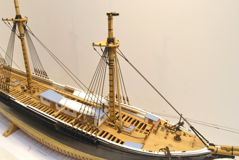
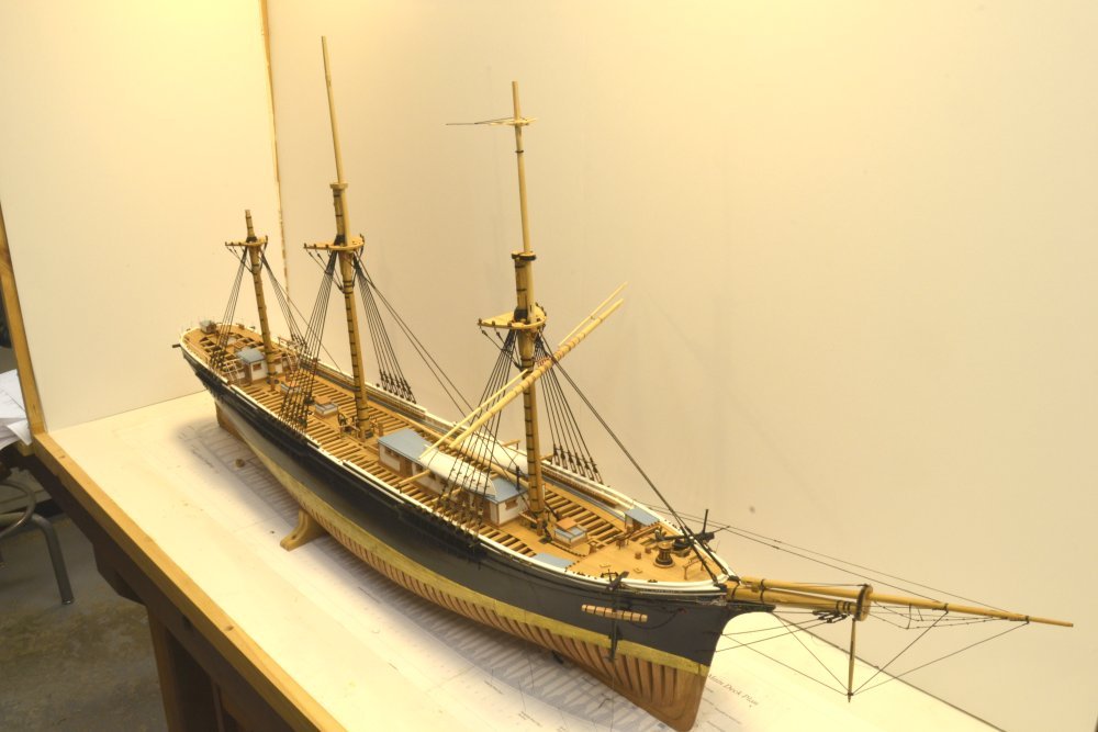
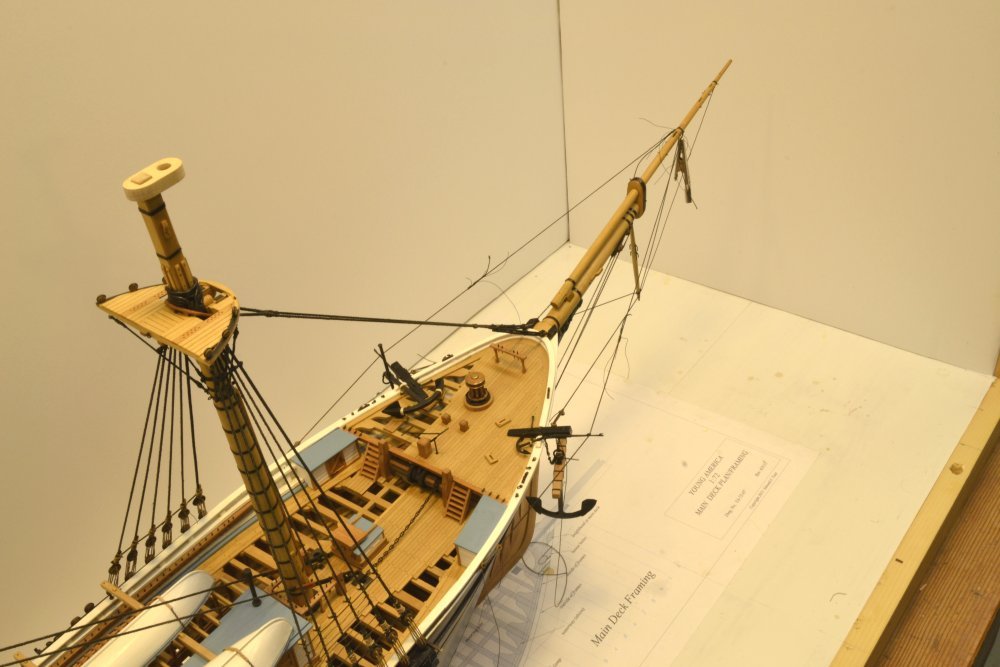
Thank you all for the comments and likes and for the continued interest in this project - now approaching its 4th year. I seem to take mostly close-up pictures but here is one I took today of the full model in its dust case. You will note construction not yet described in the posts. Running a bit behind on the posts. Below is a photo of the two fixtures I am using to hold larger spars. The one with the cam levers is used to hold square straight of tapered pieces. The one above is used to pare off the corners to form octagons and to do final rounding. It has various sizes of v-grooves along the top and dowel stops at one end of each groove. They are very simple to make using scrap material. The bases are 2x4 and 2x3 wood that can be held in my bench vise. The working surfaces are 3/4" thick pine, supported at the ends, with screws in the center to curve the working surface so that curved spars like yards will lie flat. Spacers are used to return the working surface to straight. The cam shapes are thin plywood held by flat head screws. The cam shapes and spacing require some trial and error to fit a range of sizes. Ed
- 3,618 replies
-
- 28
-
-
- young america
- clipper
- (and 1 more)
-
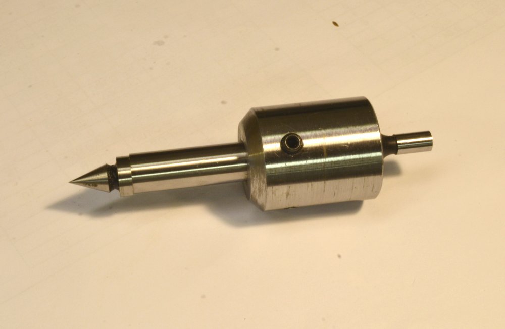
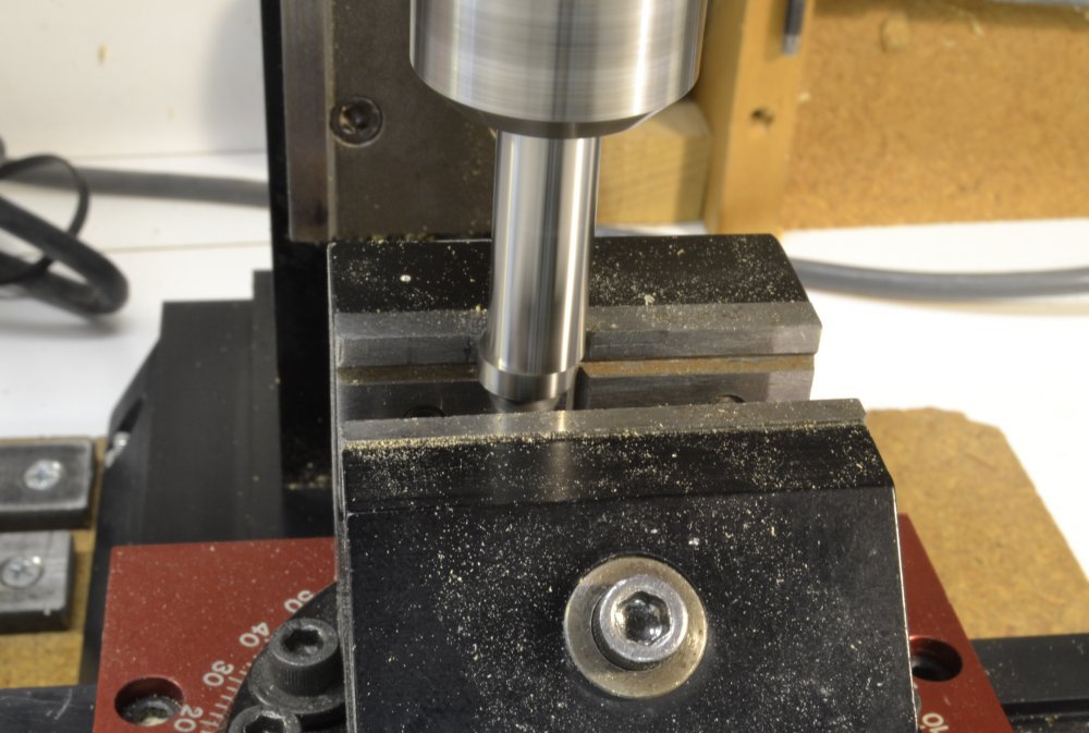
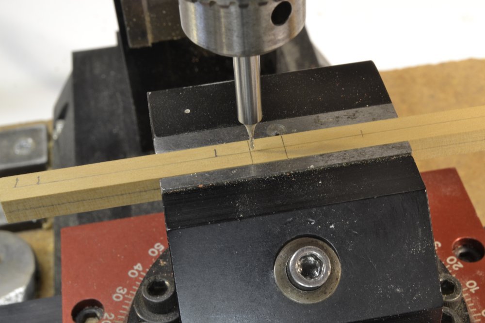
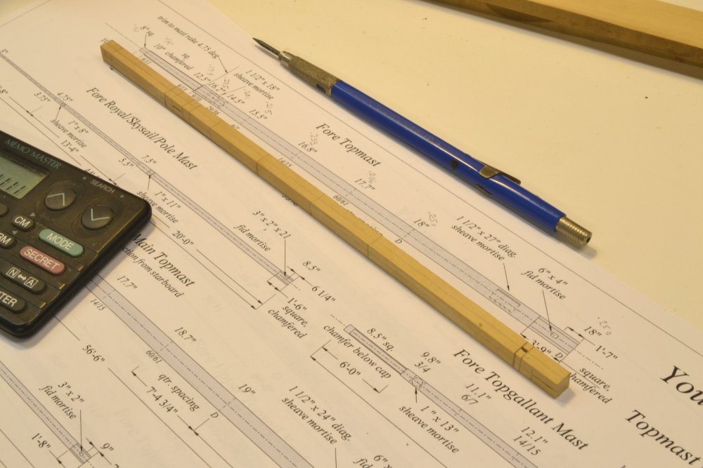
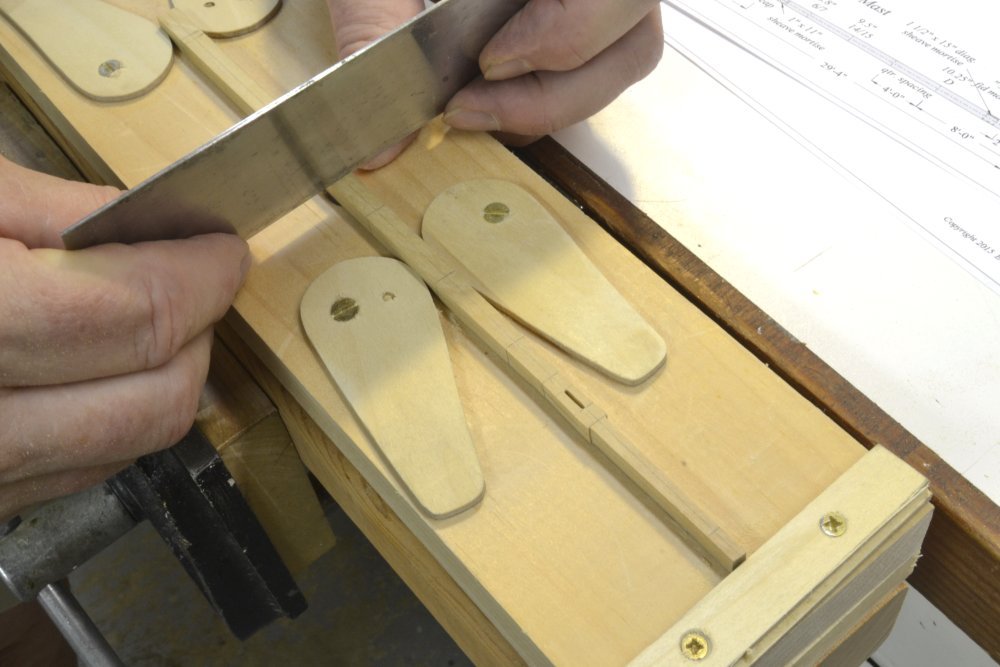
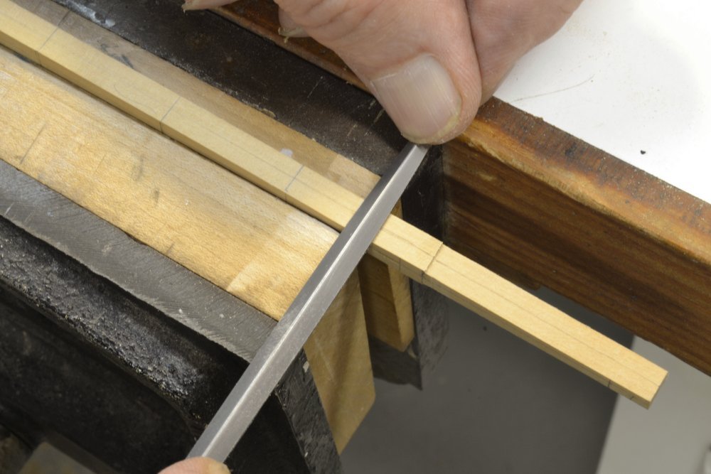
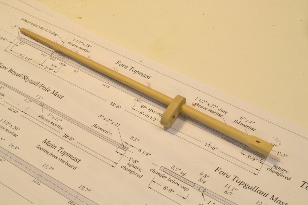
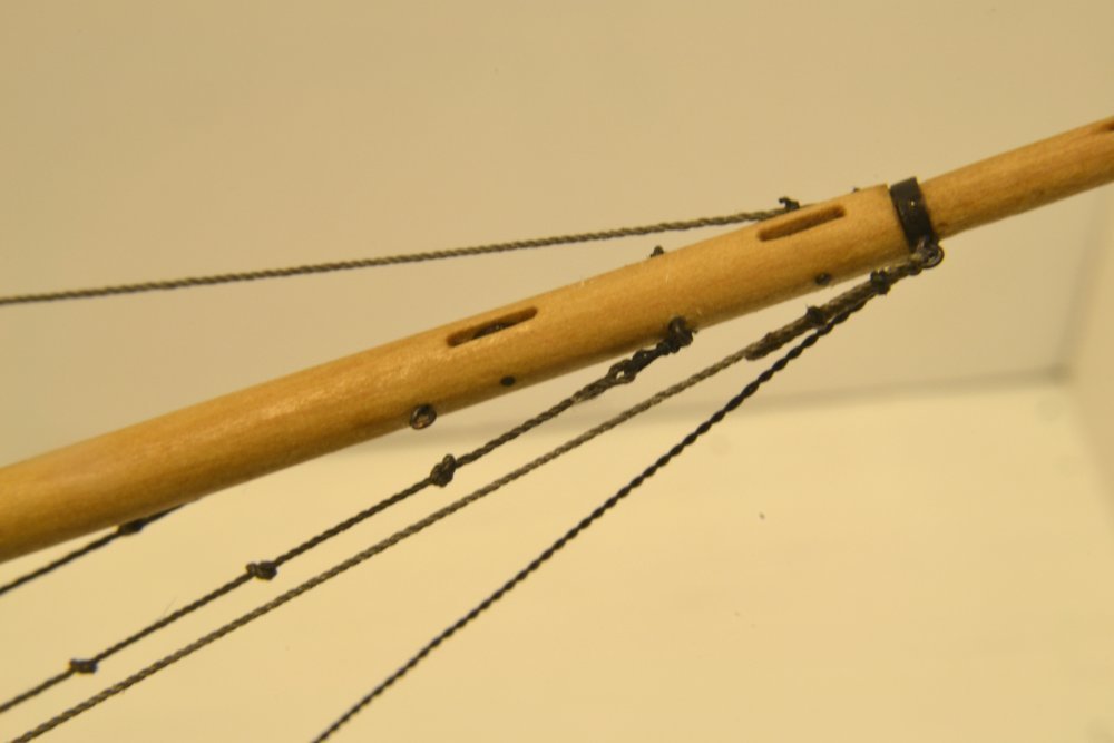
Young America - extreme clipper 1853 Part 226 – Fore Topmast 1 The fore topmast is only slightly less complex than the jibboom. It has two sheaves, one below its cross-trees for the upper topsail halyard tie, and one near the base to aid in erecting the mast. The base is square, the area below the hounds is octagonal and the minimum diameter of the spar is below the hounds so that the top of the hounds flare out to provide a seat for the cross-trees. As with the jibboom, mortises for both sheaves and one at the base for the mast fid were milled into the still-squared, untapered "first trim." In the jibboom post (Part 217), I mentioned using an edge-finer to center the mortises on the spar, rather than relying on pencil-marked center lines. This method eliminates error inherent in visually using a marked line. The edge finder that I used, set in the 3/8" Sherline mill holder, is shown in the first picture. The finder is precisely 0.375" inches in diameter. The lower section of the finder is offset from the center but moves freely in the radial direction. The pointed section at the bottom is not used in this instance. The first step was to align the fixed jaw of the milling vise parallel to the mill's X-axis. This was done using a dial test indicator mounted in the spindle as described in an earlier post. The edge finder was then installed in the spindle and used to precisely locate the face of the fixed jaw of the vise relative to the spindle centerline. The next picture shows this being done. In the picture, the finder has been lowered so the bottom part is able to rub against the vise jaw. With the mill running, the jaw is brought slowly into contact with the lower section of the finder. As the vise is moved inward, the lower section of the finder becomes more centered. When the jaw has reached the precise diameter of the finder shaft, the bottom section "kicks out" to the left as shown above. The finder is then removed and the vise moved further inward by one-half the finder's diameter, 0.1875". The spindle is thus centered precisely over the fixed vise-jaw face. In the next picture, a 1/32" bit has been fitted into a chuck on the spindle and the vise advanced by one half of the actual diameter of the spar blank, bringing it precisely over the centerline of the spar. For this very light work, the bit is held in a drill chuck. Due to the size of the spar and the short length of the milling bit, the mortises must be cut from both sides, further heightening the need for accurate centering. The less critical lengths of the mortises are set visually by lines marked on the spar. I cut all the mortises with the bit shown, then enlarge to the final width later using small files. The next picture shows the spar with two of the mortises cut. Because the lower sheave is set 45 degrees from the fore and aft slots and is located on the full-diameter, untampered lower end, this milling was later done by the same method after the octagonal shape was formed on the spar. The next picture shows the rough tapering of the square blank using a cabinet scraper. The area below the hounds is being tapered from both directions to the minimum mast diameter as shown below using a flat file. In the next picture the mast has been fully shaped. The bottom is left square with chamfered corners, the hounds are left octagonal and the masthead is left square. The final diameter of the lower section was refined to its final size using the mast cap as a gauge. The last picture shows the topmast temporarily mounted on the lower mast. As with the bowsprit cap, the mast cap shown here was easy to make because the lower masthead tenon and the diameter of the lower end of the topmast are 18", converting to a convenient ¼" drill size at 1:72. Precision in mast cap dimensions is important so that the masts will be properly aligned. For all the remaining caps, where the hole sizes are less convenient, a different process will be described later. Ed
- 3,618 replies
-
- 33
-
-
- young america
- clipper
- (and 1 more)
-
Thanks you all for the comments and likes. Welcome back, Druxey. Ed
- 3,618 replies
-
- 3
-
-
- young america
- clipper
- (and 1 more)
-
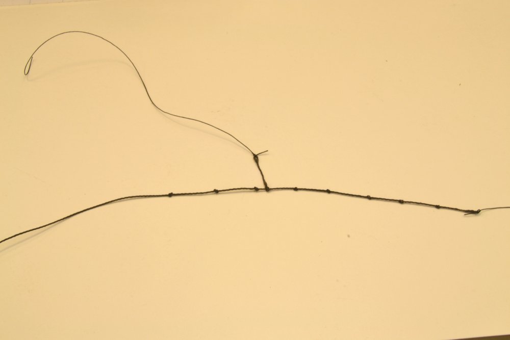
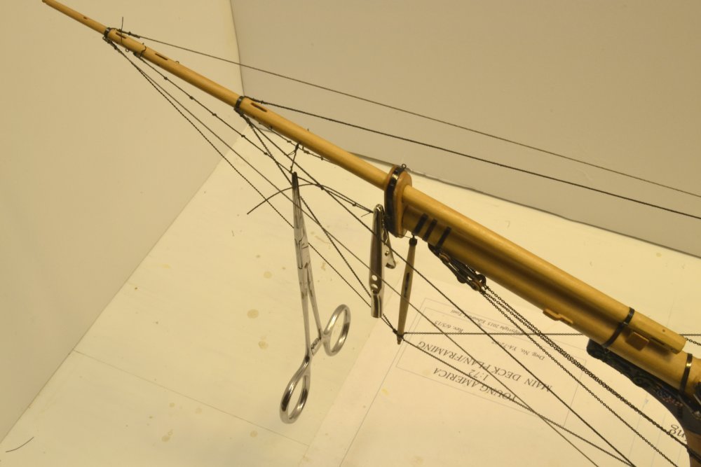
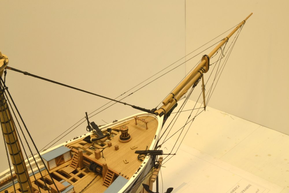
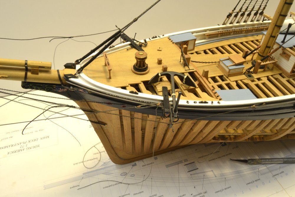
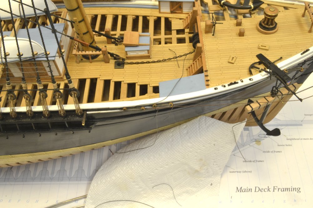
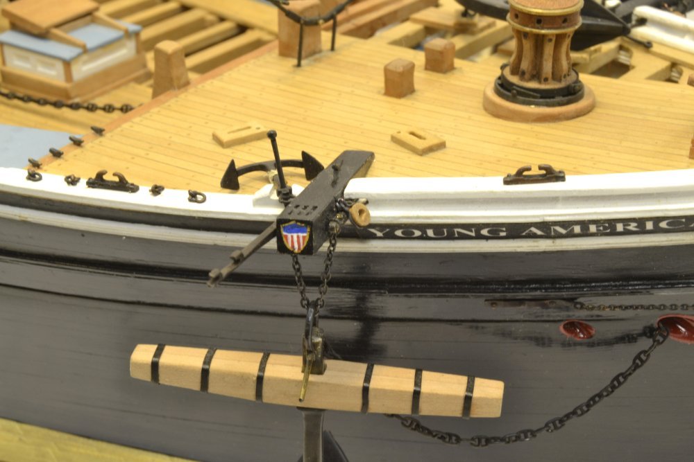
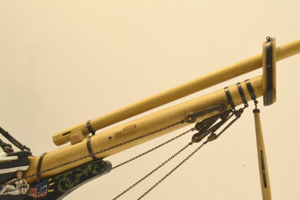
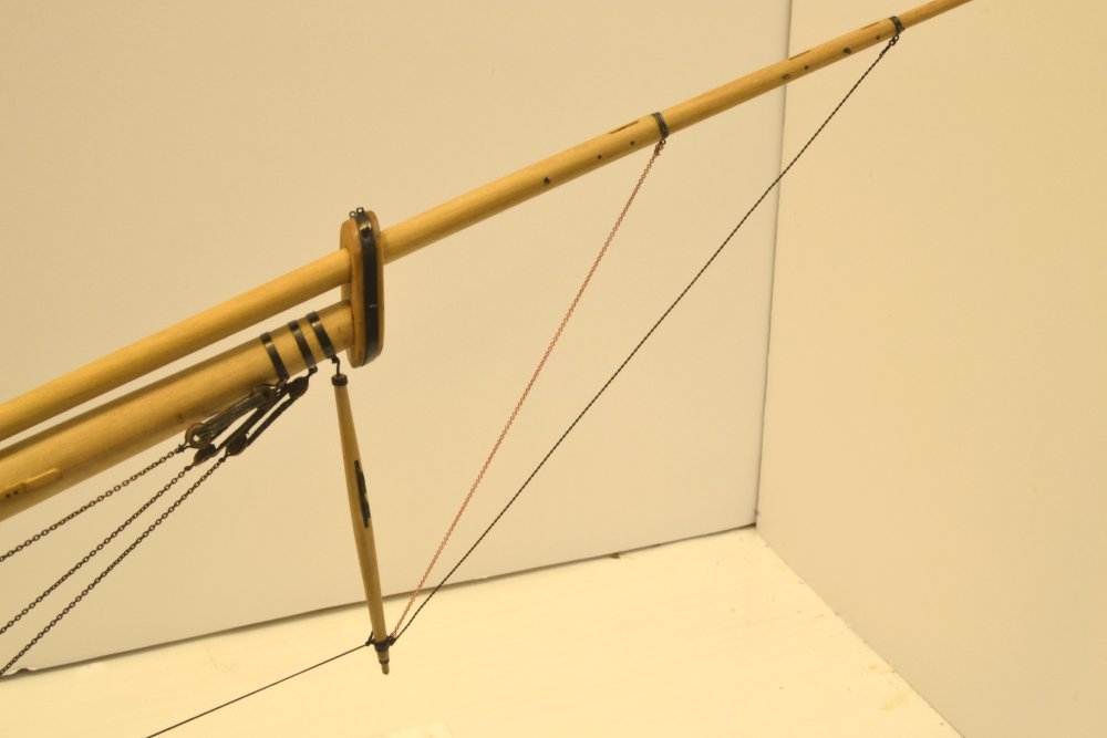
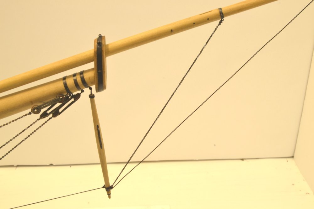
Young America - extreme clipper 1853 Part 225 – Bowsprit Standing Rigging Foot Ropes/Lifelines Footropes from the bowsprit cap out to the end of the flying jibboom allowed crew to work along the jibbooms on tasks like furling and bending outer jibs. Because of the inclination of the bowsprit these ropes were knotted along their length to prevent slipping. There was a single stirrup supporting the center of the foot rope. The first picture shows a prefabricated, 3½" footrope ready to be installed. The forward end of the rope is eye spliced, as are both ends of the short stirrup. Both these eyes have lashing thread tied to the eye. The lower end remains unspliced. The eye at this end will be formed with the rope in place so the length can be set. In the next picture the port footrope and its stirrup have been lashed to eyebolts along the spar and the attachment to the cap is being formed. The weight of the surgical clamp suspended from the center holds the stirrup straight so the foot rope length can be set. The lashing thread at the cap is passed through the eyebolt and tied to the rope where the eye splice will be made. The loose rope end is threaded through itself at that point to form the eye which is then glued. The alligator clip is clamping the eye splice while the glue dries. The lashing at the cap will then be completed. The next picture shows an eye splice lashed to an eyebolt. The next picture shows an all-too-typical tangle of clamps and thread ends during the process. In this picture, lifelines from the knightheads out to an eye in the top of the cap band may be seen. These are secured like the footropes with spliced eyes and lashings. The last two pictures show the completed standing rigging of the bowsprit. More standing rigging lines will be added later, but these will be components of the foremast structural rigging. There will also be various running rigging lines added later – mostly those associated with jibs and staysails. All of this bowsprit rigging could have been done before the lower masts, since with the fore stay attached to the knightheads, it is independent of those structures. However, the bowsprit should be rigged before the fore topmast, so its stay can be secured and tensioned with the bowsprit rigging in place. Next: the fore topmast. Ed
- 3,618 replies
-
- 28
-
-
- young america
- clipper
- (and 1 more)
-
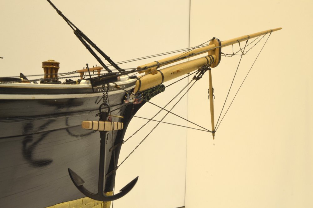
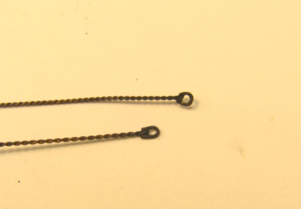
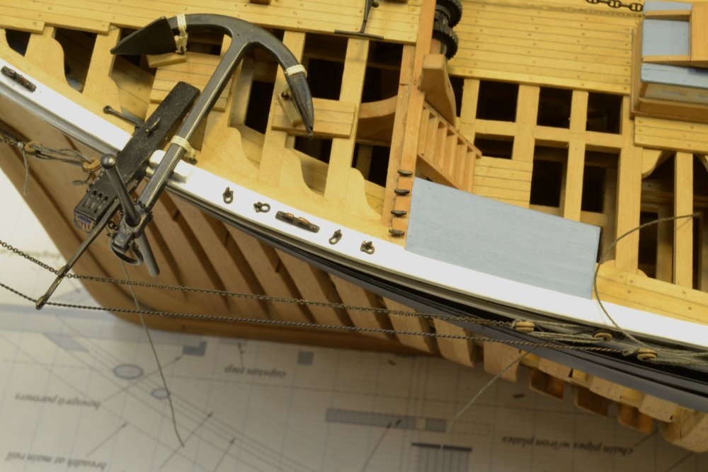
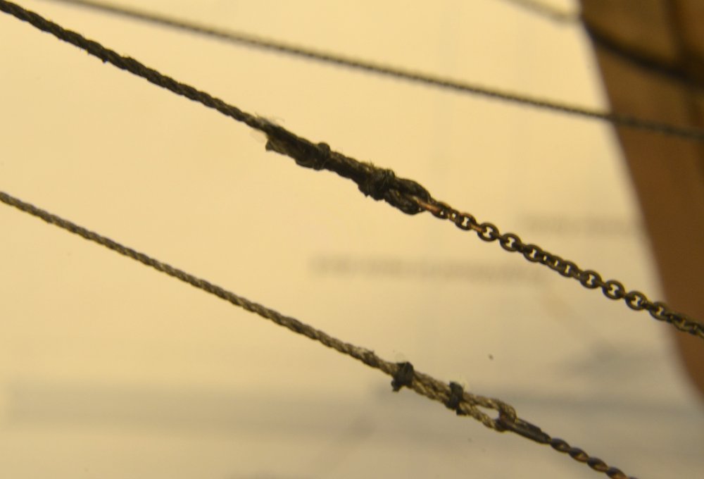
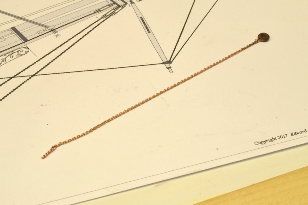
Young America - extreme clipper 1853 Part 224 – Bowsprit Standing Rigging 3 Jib Boom Guys The jibboom and flying jibboom guys provided lateral support for the outer bowsprit. They are 5 ½" rope at the forward ends and 54 links per fathom (lpf) chain where they pass through the whisker booms and back to where they belay to hearts on the outer rail. I used the smallest (40 lpi) model chain available for this size chain. The first picture shows the port jibboom guy secured and the starboard guy draped through its whisker boom cleat. Loose ends of both the line and the seizing yarn may be seen in the picture. The rope sections are seized at both ends – to eyes on the boom and to the chains. The next picture shows a seizing being tied at a boom eyebolt. The rope is held taut with the alligator clip shown in the picture. After tying each seizing a drop of darkened glue is placed on the knot. When this has fully dried the excess seizing thread and the excess line are clipped off. Another drop of diluted glue is applied to further seal the knot and the cut rope end. At this stage the line is given an initial tension using the heart lanyards. The next picture shows both jibboom guys essentially installed. The next picture shows the 40 lpi chain at the whisker boom. This picture tells me that the whisker boom needs straightening. These have occasionally run afoul of my hands and arms. They are very vulnerable to this. Perhaps the chains will help. Flying Jibboom Guys The flying jibboom guys are lighter, 3¾" rope and 74 lpf chain. Chain of this size is made by twisting copper wire. Some of this, with shackles soldered to the ends, is shown below. This picture illustrates some variation in the simulated links per inch – very difficult to discern by the naked eye. The next picture shows the outer guy on the starboard side and the hearts and lanyards on both guys on that side. The eyebolts are anchored in toptimbers, spaced to keep the two sets of hearts from fouling each other. Again, the lanyards are left unseized until final tensioning later. The paper toweling in the picture was used to catch drips of the liver of sulfur solution used to touch up the blacking on the chains. The next picture shows the chain sections of the guys on the port side. The next picture is an ultra-close up of the two rope/chain seizings. All the line used so far on the model is linen dyed with India Ink, except for some of the lashings that are cotton. The seizing thread is black quilting cotton. The foot ropes and lifelines that will complete this phase of the bowsprit rigging will be covered in the next part. Ed
- 3,618 replies
-
- 31
-
-
- young america
- clipper
- (and 1 more)
-
Fantastic attention to detail, Johann. Extraordinary! Ed
-
Young America - extreme clipper 1853 Part 223 – Bowsprit Standing Rigging 2 Martingale Backstays The first picture shows the two prefabricated martingale backstays with hearts attached, secured to eyebolts on the lower end of the martingale. These are of 40 lpi copper chain, simulating smaller 74 lpf chain as mentioned earlier and as used on the inner martingale stay in the last part. They were pre-measured before attaching the eyebolts and heart shackles at the ends. The temporary "backstay" tensioning thread is still in place. The backstays will be secured to hearts anchored to eyebolts on the catheads. The heart on the starboard cathead is shown below. The next picture shows the lanyard on the port backstay threaded up and the stay being tensioned. The starboard stay has been installed and the two are being adjusted to provide tension on the inner and outer forward stays and to pull the martingale into a side-to-side vertical position. The next picture shows the installed backstays with the temporary tensioning thread removed. The next picture shows the hearts on the starboard side. The lanyards on both sides remain unsecured so that final tension adjustments may be made later when foremast stays are installed. After those final adjustments, both the loose lanyard ends will be seized to their mates and clipped off. The last picture shows a pair of these seizings on one of the bowsprit backstays before clipping off the excess seizing thread. Ed
- 3,618 replies
-
- 36
-
-
- young america
- clipper
- (and 1 more)
-
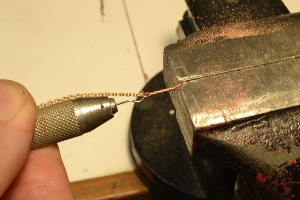
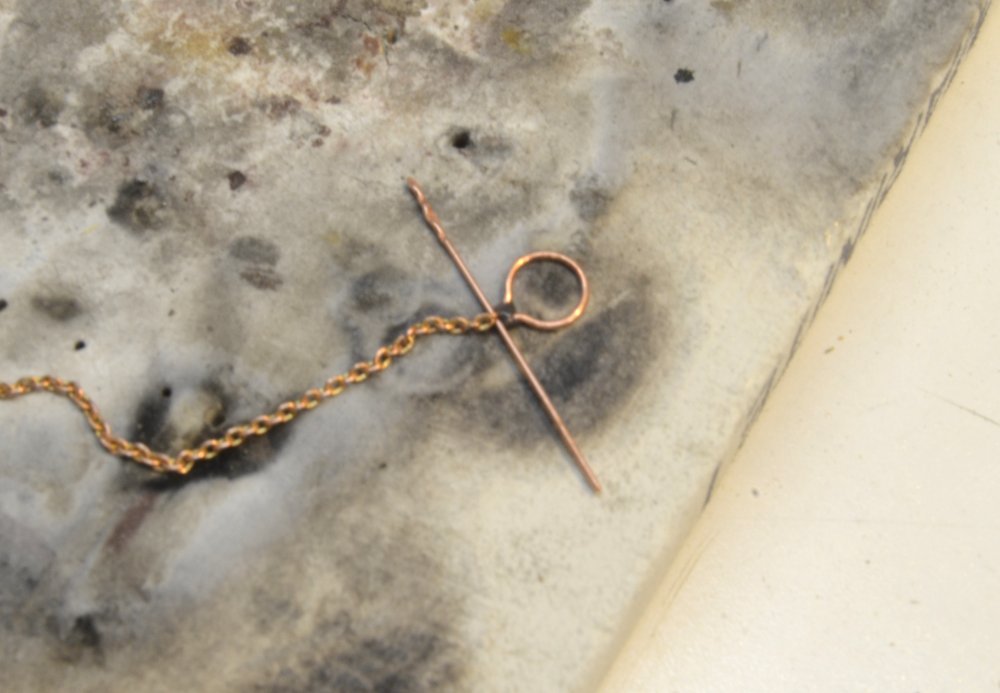
Thanks for all the likes and comments. Pat, the twisted wire is as good a solution as I could come up with. There will quite a lot of small chain on the model - all the sheets and halyards for example - so something had to be done. By eye it looks quite good - maybe its my eyes. Photos depend on the distance. Ultra-close, it looks like what it is. The trick in making it is to get the turns to approximate the links/inch uniformly. Too much tension and the small (28-32 gauge) wire will break - too little and the distribution gets non-uniform. Seems to work for copper and brass. Brass is stronger but then there is the blackening. Ed
- 3,618 replies
-
- 8
-
-
- young america
- clipper
- (and 1 more)
-
Hi Greg, I seldom use solvents any more to clean brass or copper before blackening, With copper and LOS, buffing seems to be sufficient, especially important over areas heated by soldering. Completely buffing chain is not so easy, but multiple brushings with LOS seems to work. Oxide from soldering heat, even with pickling after soldering, seems to be the main problem on copper with LOS - needs to be buffed off if possible. Rubbing or brushing with the solution helps - but you are right LOS is pretty easy to use. I still treat brass with the blue selenium solution by dipping small, pickled and/or buffed parts. For larger parts I brush or use a cotton swab full strength followed by rinse. I do not always rinse LOS. Unlike the selenium salts, it neutralizes. Nothing is foolproof with blackening. I keep looking for better means. WinOx on brass works a lot like LOS. I got some Jax pewter recently and that has possibilities. Still the black art. Ed
- 3,618 replies
-
- 8
-
-
- young america
- clipper
- (and 1 more)
-
Young America - extreme clipper 1853 Part 222 – Bowsprit Standing Rigging 1 Much of the bowsprit standing rigging is/was chain. In the mid-19th century chain was used not so much for sheer strength but primarily for its durability in situations where physical abuse could be expected. Later, iron or steel wire would displace chain and rope. The bow of the ship was exposed to buffeting by the sea and objects that might be floating in it, as well potential damage in collisions with docks, etc., however slight, hence the amount of chain in its structural rigging. Chain sheets and halyards that also suffered considerable wear will be discussed later. Chain specifications have been hard to uncover in primary sources, so where Bill Crothers specified sizes on his drawings I have used those. His sources for these (and other questions) were on my list to discuss with him but that last meeting never occurred. However, knowing the intensity of his research, I am confident in his sizing. For lines he omitted from his drawings, I plan to calculate rope/chain equivalents from contemporary data in Luce, Seamanship, 1868. Chain has been a puzzle Bobstays continued In the last part, fabrication of one of the chain bobstays was described. In the first picture the two bobstays have been rigged. The forward ends are secured to eyebolts in the bowsprit using wood hearts with lanyards. These allowed tensioning of the stays. The fine thread seen in the picture are ends of the seizings that secure the lanyards to their adjacent parts and will be clipped off. A simpler, but less authentic, method of securing the ends was adopted later to eliminate the visible ends that are difficult to completely remove at this scale. Bowsprit Shrouds The next picture shows one of the bowsprit shroud fabrications before installation. The shrouds and bobstays are all chain of ~30 links per fathom (lpf), i.e. 30 links per inch at 1:72. The connection to the heart is similar to that shown above and in the last part. At the other end, an iron plate with an eyebolt is used. This will bolt to the outer hull above the hawse holes as shown in the next picture. This picture also shows one of the martingale backstays rigged to the cathead that will be discussed later. The next picture shows the forward fastenings of the bobstays and shrouds. Martingale Stays The next picture shows the inner and outer martingale stays. The inner, unblackened, stay was chain of 54 llpf and is modeled using the smallest chain I could find. At 40 links per inch it is somewhat heavier than specified, but representative. The outer stay was lighter at 74 lpf. This fine chain was simulated by twisting up two strands of 28 gauge copper wire under fairly low tension. This method produces a very reasonable small-sized chain substitute. Unfortunately, small chain is not very photogenic. These two stays were sized with the martingale held vertical by the temporary thread "backstay" in the picture. The next picture shows these two forward chain stays after blackening. The martingale will be held vertical by two backstays that run back to hearts and lanyards on the cathead. When added, these attachments will allow fine adjustments to the position of the martingale. Next time. Ed
- 3,618 replies
-
- 34
-
-
- young america
- clipper
- (and 1 more)
-
Hi Maury, I second Rogers comments. I do not find Castello to be very good for bending. Another species to consider is hard maple. As always, straight grain is essential. Ed
- 525 replies
-
- 3
-
-
- anchor hoy
- hoy
- (and 1 more)
-
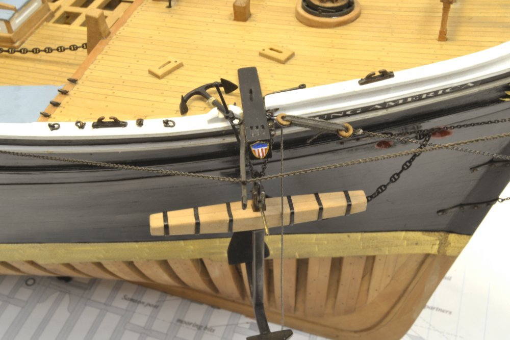
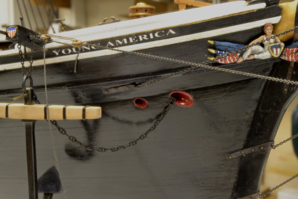
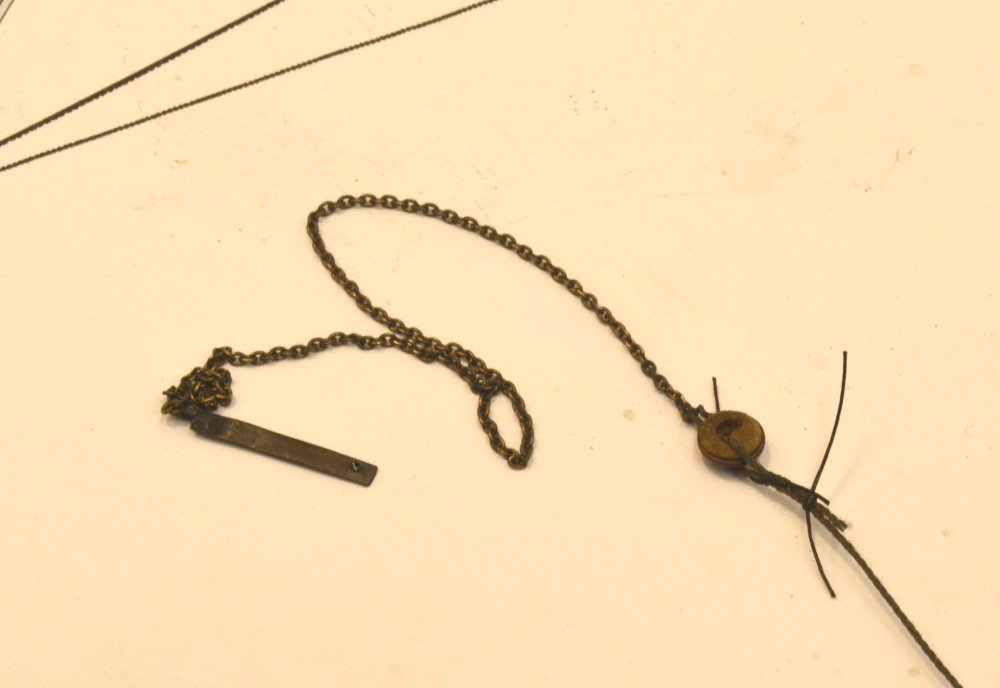
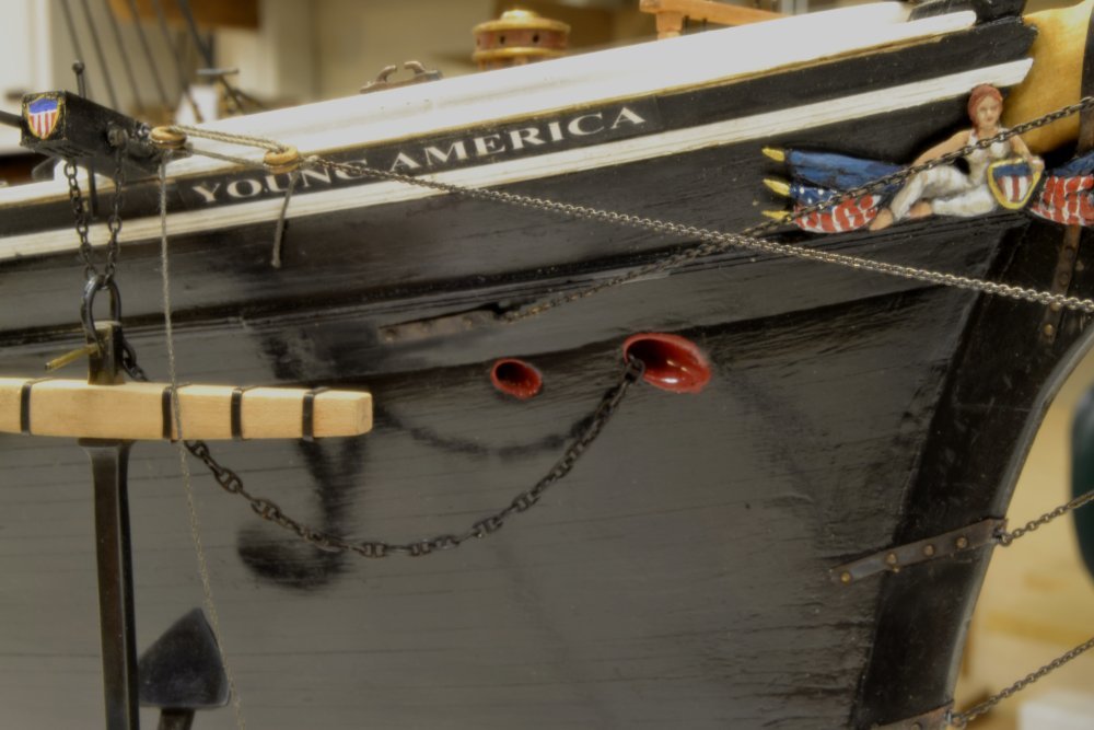
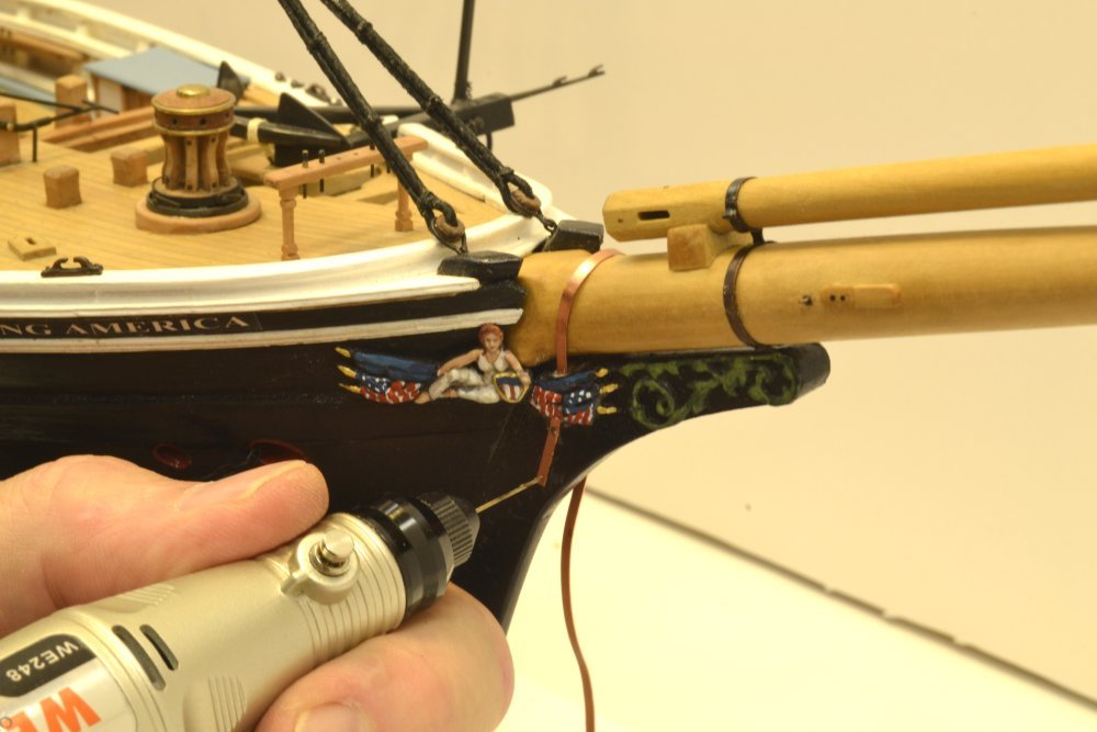
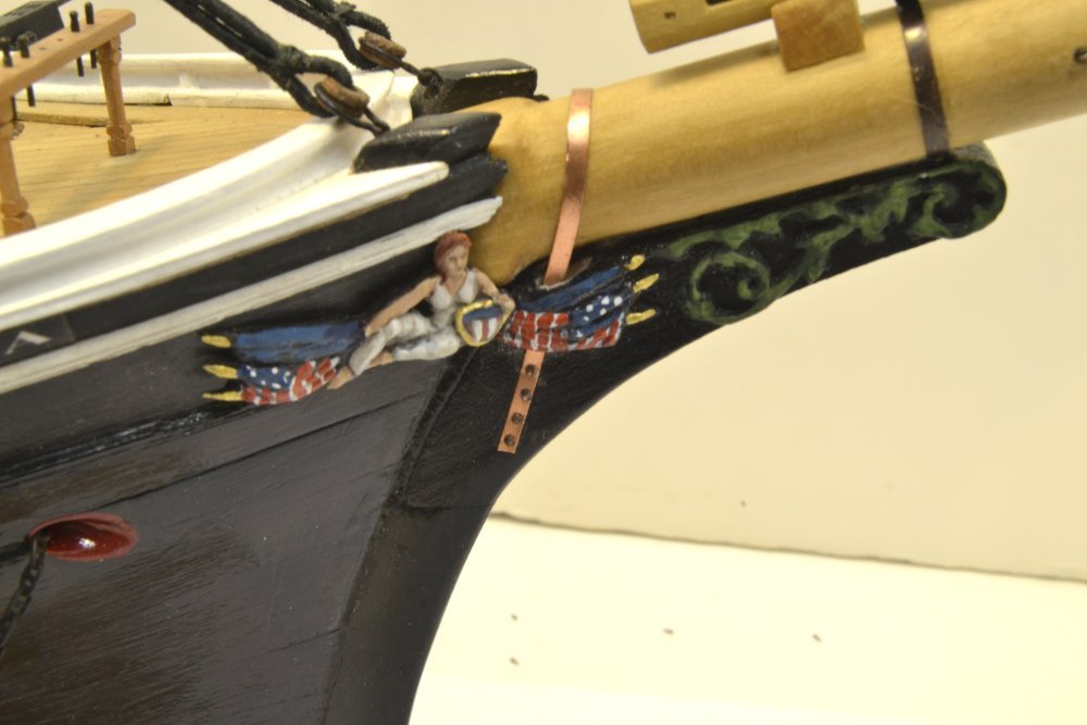
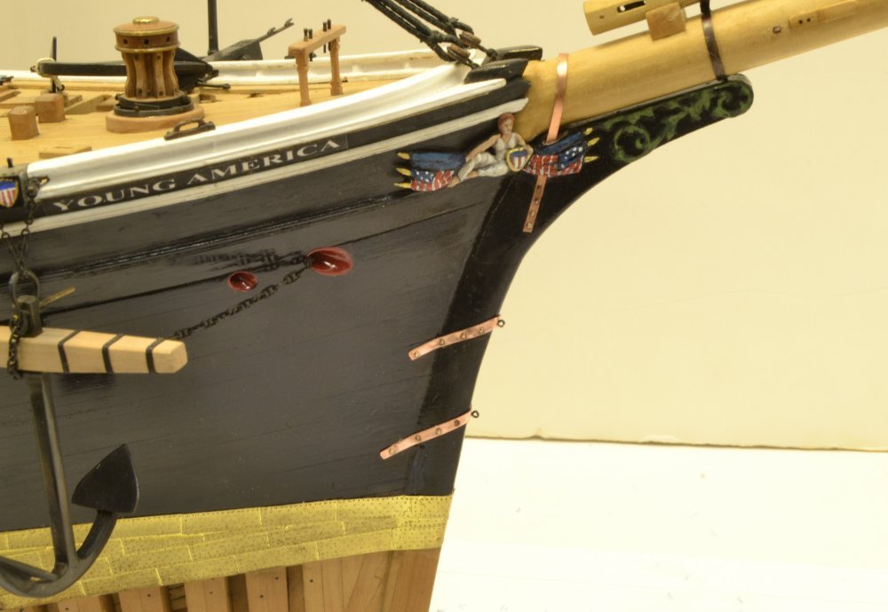
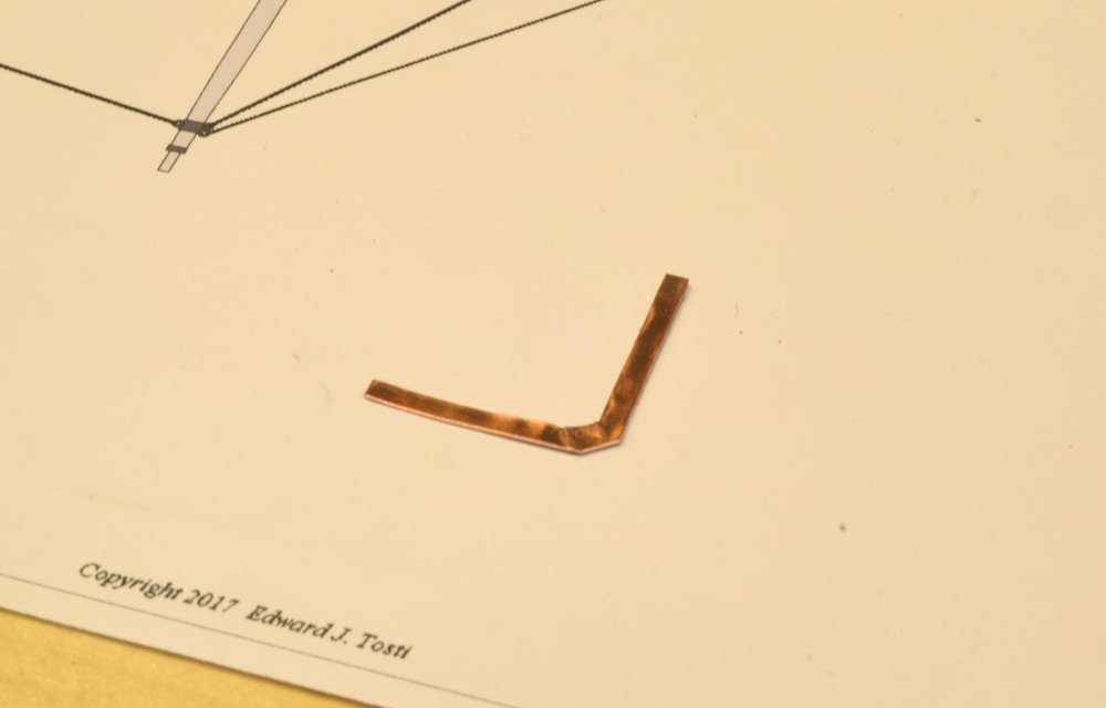
Young America - extreme clipper 1853 Part 221 – Bow Ironwork The final step in permanently securing the bowsprit was to install the iron-strap gammoning. This passes over the top of the bowsprit just forward of the knightheads on either side, and bolts to the upper part of the stem assembly. The first picture shows a bolt hole being drilled through the strap and into the wood. With one side secured, the strap was tightened over the spar, hammered down to fit at the top, and bolted to the other side. Because the figurehead moldings were fitted into the area between the hull and the stem, slots for the banding had to be sawed out. The next picture shows the installed gammoning. After blackening, the slot through the figure molding will need to be touched up with paint where it was sawed out. The next picture shows the two anchor points for the inner and outer bobstays – also iron straps bolted to the stem and hull. Because these are angled at the forward end, the copper strips for these were cut out before bending as shown in the next picture. This shape was then bent to fit over the stem, shaped to the hull with the apex up, drilled and bolted. Holes for eyebolts were then spotted and drilled through the forward face and into the stem. Bobstays The next picture shows one of the bobstays before blackening. The eyebolt was twisted up with the chain attached as shown below. The strap for the 12" wooden heart was fabricated as shown below just prior to soldering. The strap was first formed around a heart with a shackle to connect to the chain – much like the deadeye straps made earlier. The chain was threaded on to the straight bolt piece before soldering. The chain lengths for these was measured with the eyebolt end temporarily placed in the stem and the chain cut off to allow space for rigging the two hearts just behind the cap. More on this in the next part. The chain is about 30 links per inch, which corresponds to 30 links per fathom at 1:72. This is the largest size chain used on the bowsprit standing rigging. More will be said on chain sizing and modeling in the next part. Ed
- 3,618 replies
-
- 27
-
-
- young america
- clipper
- (and 1 more)
-
Not on the drawings, Daniel, but I refer to it generally in the text and specifically on significant points. There is a pretty full discussion of this issue in the Introduction to Vol II. Ed
- 3,618 replies
-
- 1
-
-
- young america
- clipper
- (and 1 more)