EdT
-
Posts
2,214 -
Joined
-
Last visited
Content Type
Profiles
Forums
Gallery
Events
Everything posted by EdT
-
Druxey, I often resorted to the method you describe in the earlier days of the model - I guess up until the poop monkey rail was installed. Very effective if you pay attention to your grip and nearby obstacles. Not so good with masts and rigging. I believe I will be able to get everything out before completion, but having to stop and go fishing when in the middle of something gets very irritating. I have a thin brass rod with a wrapping of sticky carpet tape on the end that works very well if you can see the part. Ed
- 3,618 replies
-
- 4
-

-
- young america
- clipper
- (and 1 more)
-
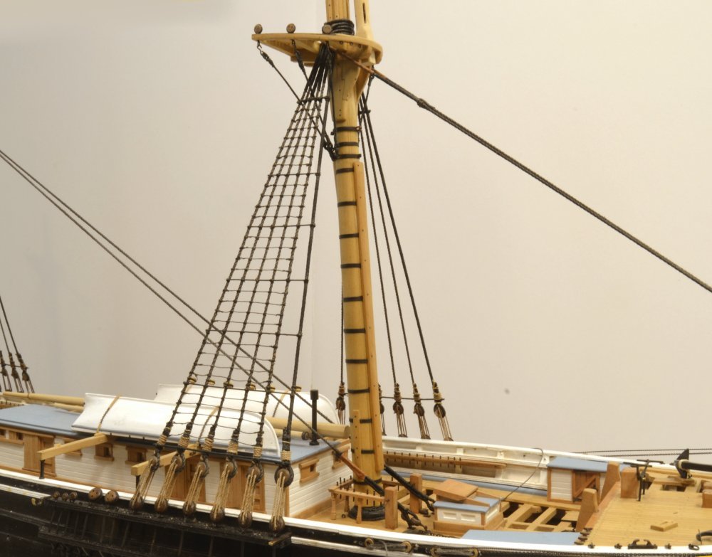
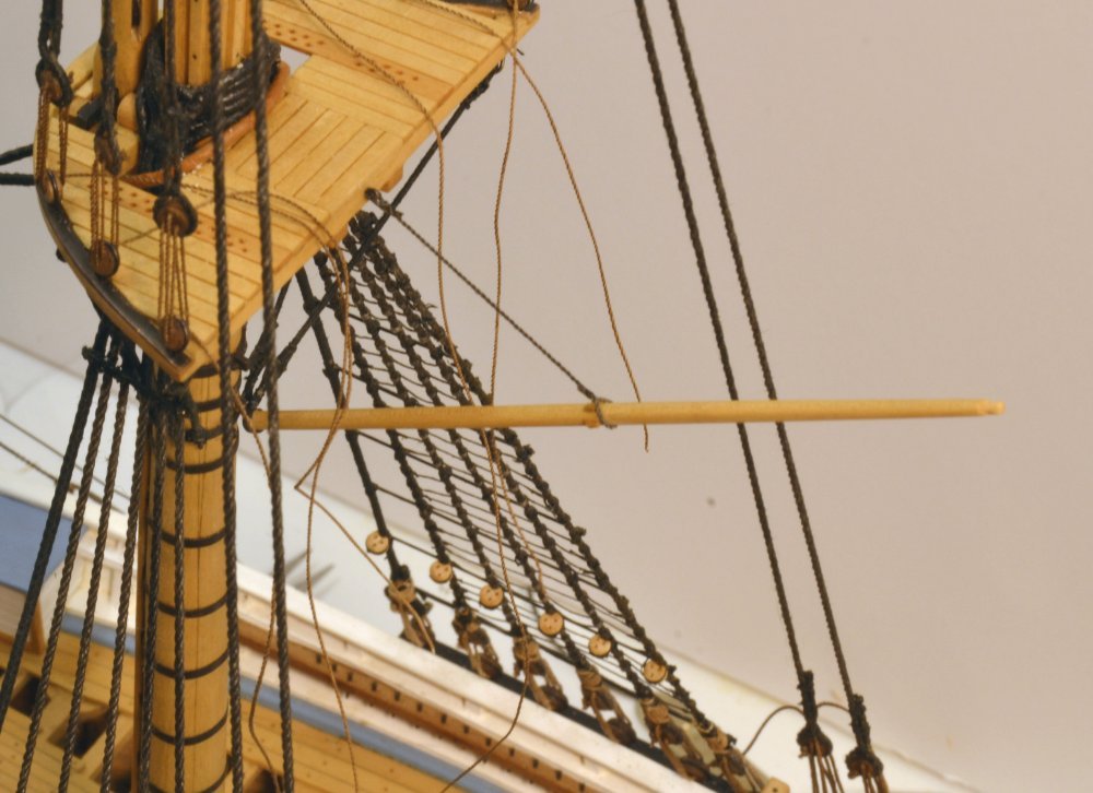
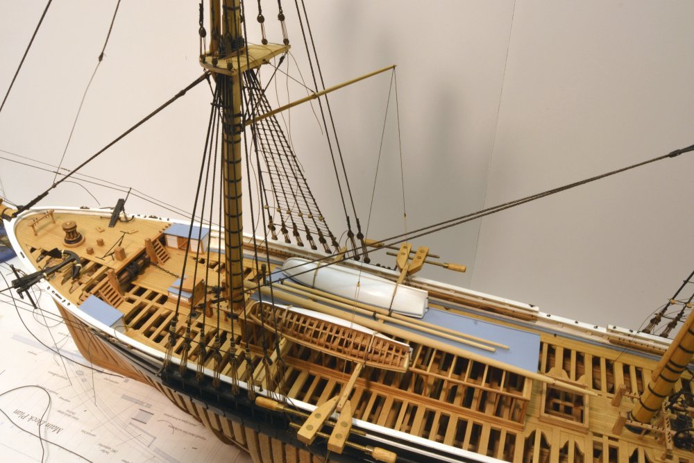
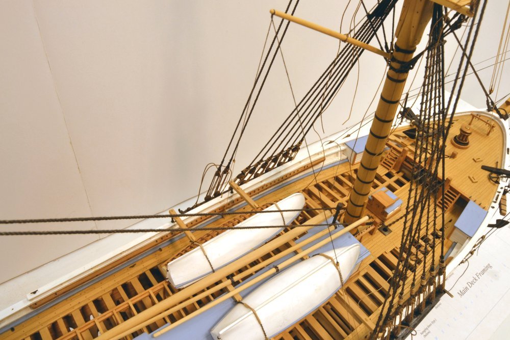
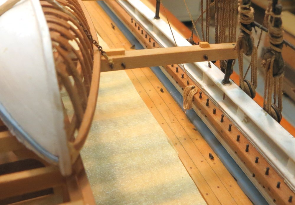
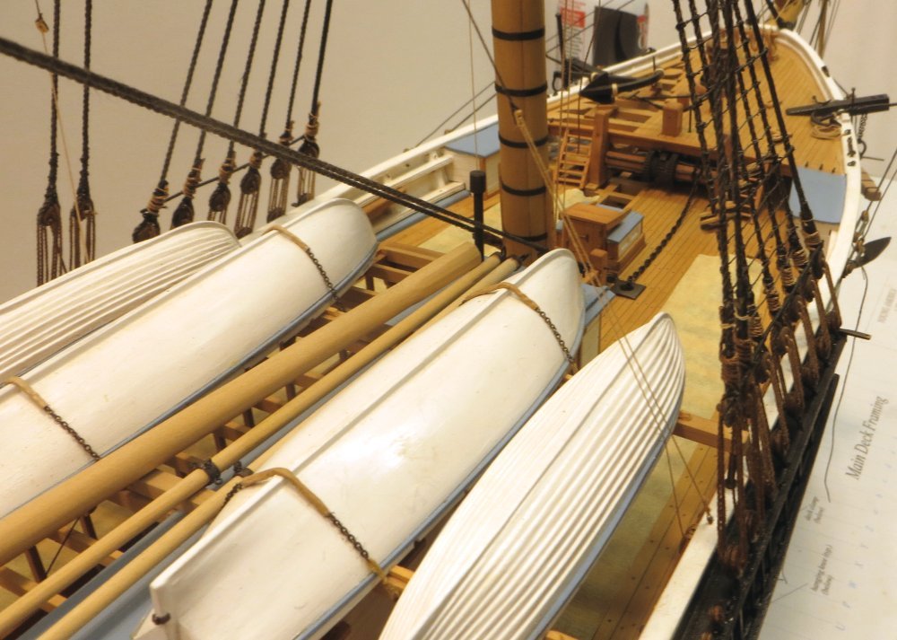
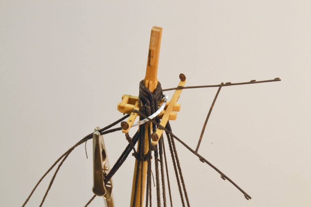
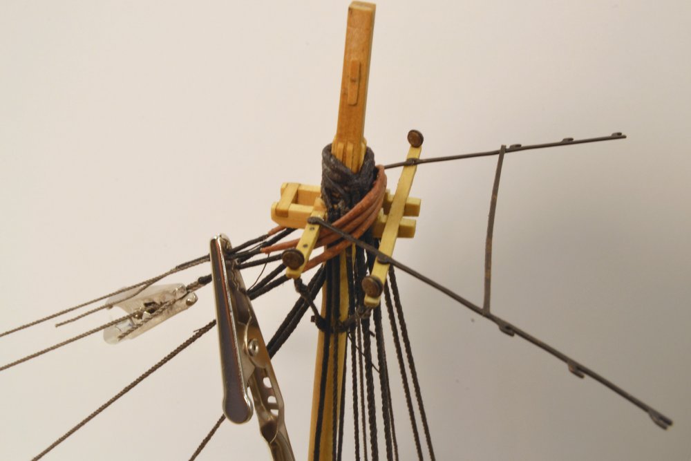
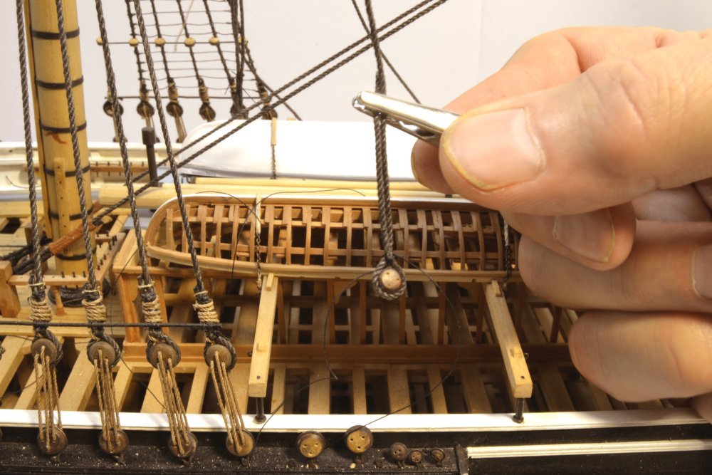
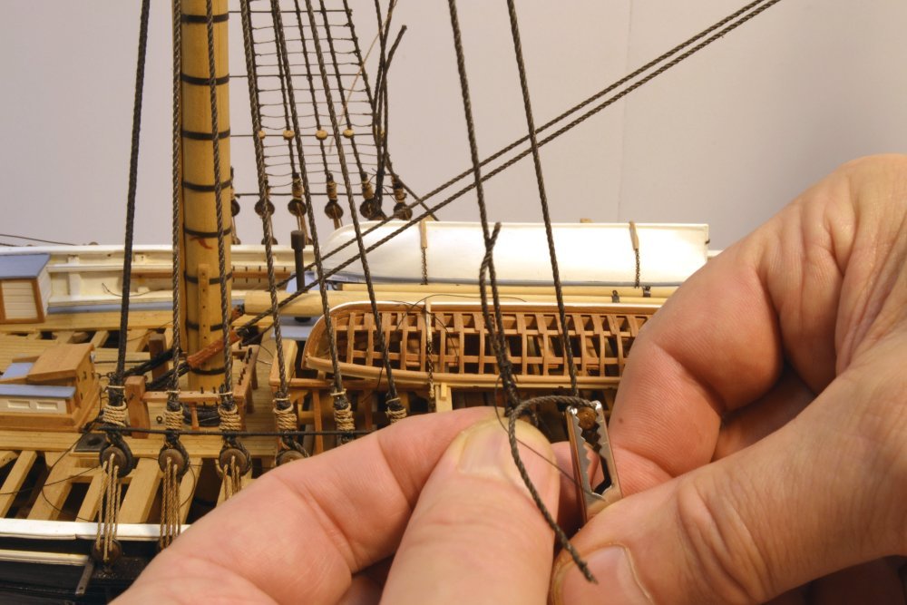
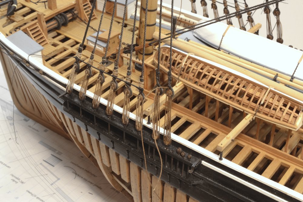
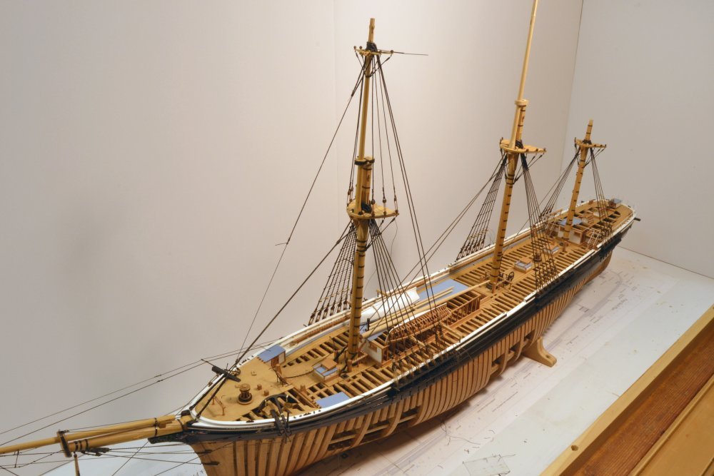
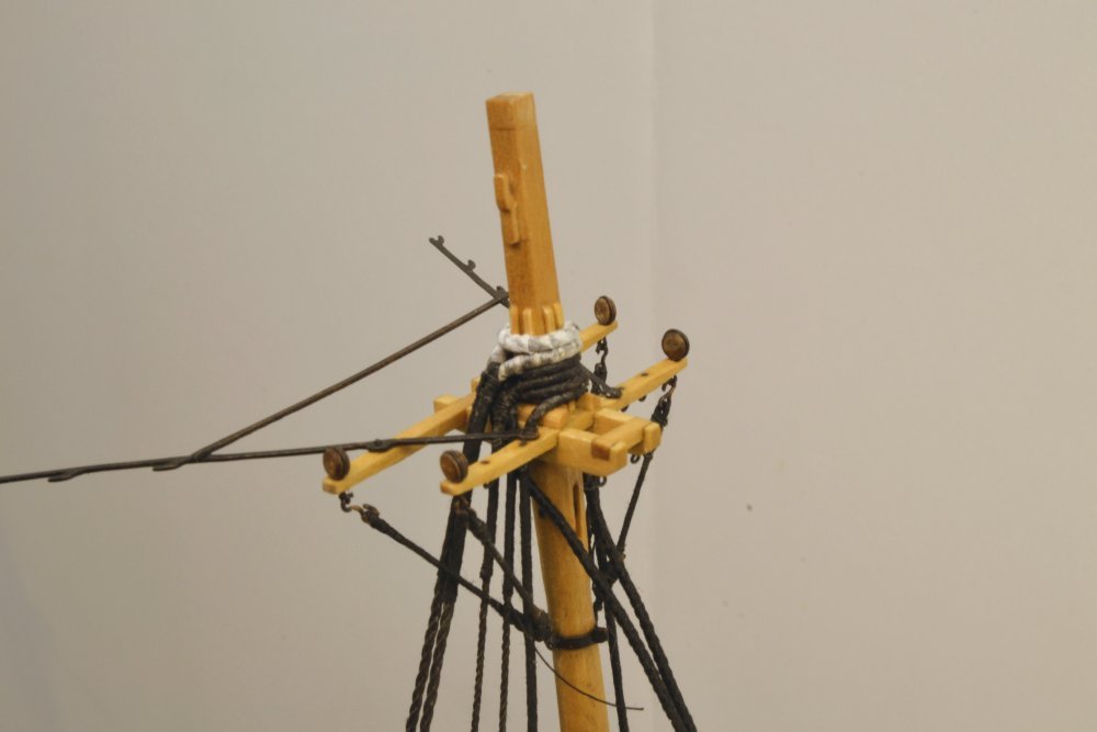
Young America - extreme clipper 1853 Part 237 – Fore Spencer Gaff The term "spencer" describes gaffs rigged on masts with square sails – except for the spanker gaff at the mizzen. They were used to support fore and aft sails that were occasionally used, or sometimes to suspend pennants to keep them out of the other rigging. The fore spencer gaff is shown in the first picture. The gaff is a small, very simple spar attached to the mast with a gooseneck/eye fitting. Stops for the standing lift are roughly centered on the spar as shown in the picture. The upper end of the lift has an eye splice shackled to the eyebolt in the top. A stop cut into the end of the spar will take a doubled "vang" pendant pair with a single block spliced into each end. The long pendants may be seen in the next picture. Each vang pendant is attached to a simple whip, with the standing end seized to an eyebolt on the main rail. The fall is belayed nearby on the main pin rail. In the picture the falls are temporarily clamped to center the gaff. The next picture shows them belayed to the main pin rails port and starboard. The limited required movement of the gaff requires a relatively short fall, so the coil of rope shown in the next picture is fairly small. The masking tape shown over the open beams, does not do a lot for the photographs, but my sanity demands it. I finally acquiesced to this after yet another part dropped into the hold and could not be retrieved. While it is relatively easy to blow out small bits of thread, the main mast fid did not respond to this. Finally, a test for clearance around the outboard boats is shown in the next picture. I need to think about this and decide if a lead block would be appropriate for this relatively small line, perhaps on one of the backstays. I love rework. Ed
- 3,618 replies
-
- 31
-
-
- young america
- clipper
- (and 1 more)
-
Yes, I do the same. For these very small ones I used just one hitch - a simple overhand knot. Ed
- 3,618 replies
-
- 2
-
-
- young america
- clipper
- (and 1 more)
-
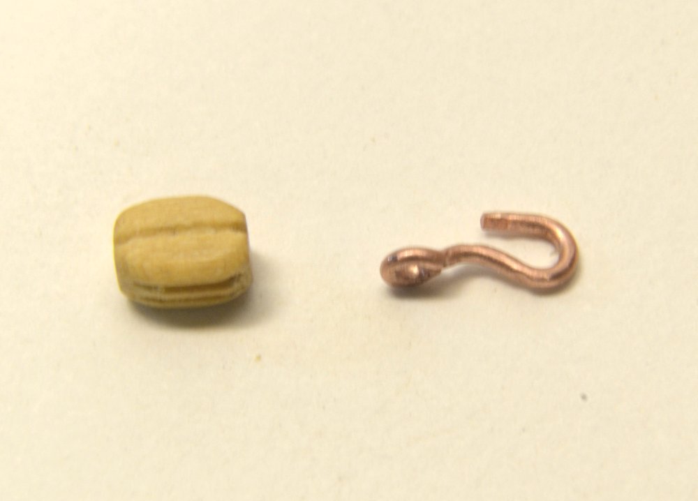
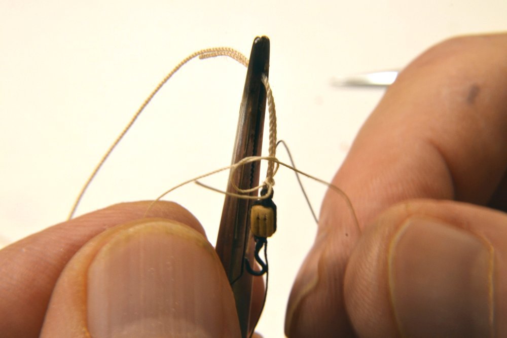
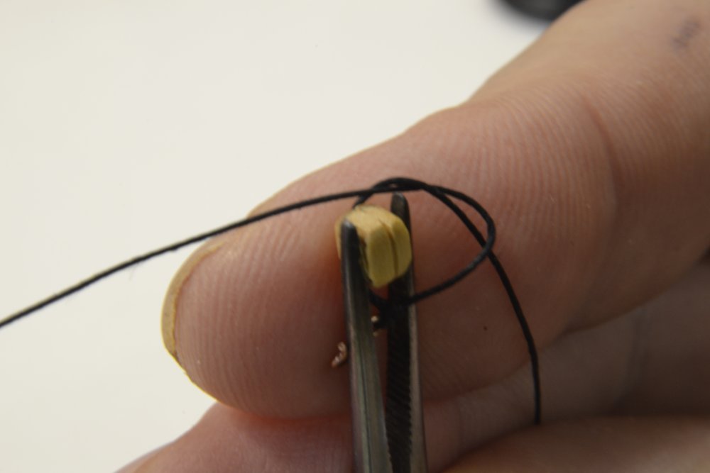
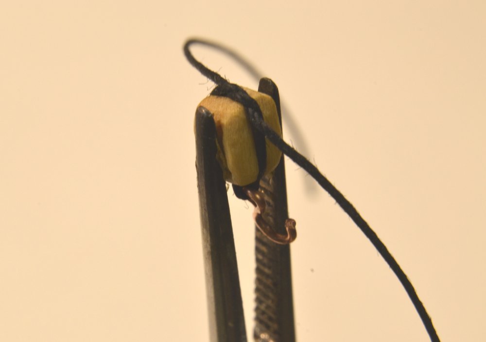
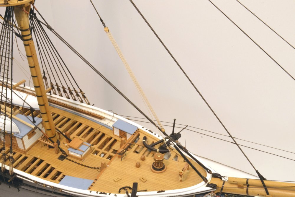
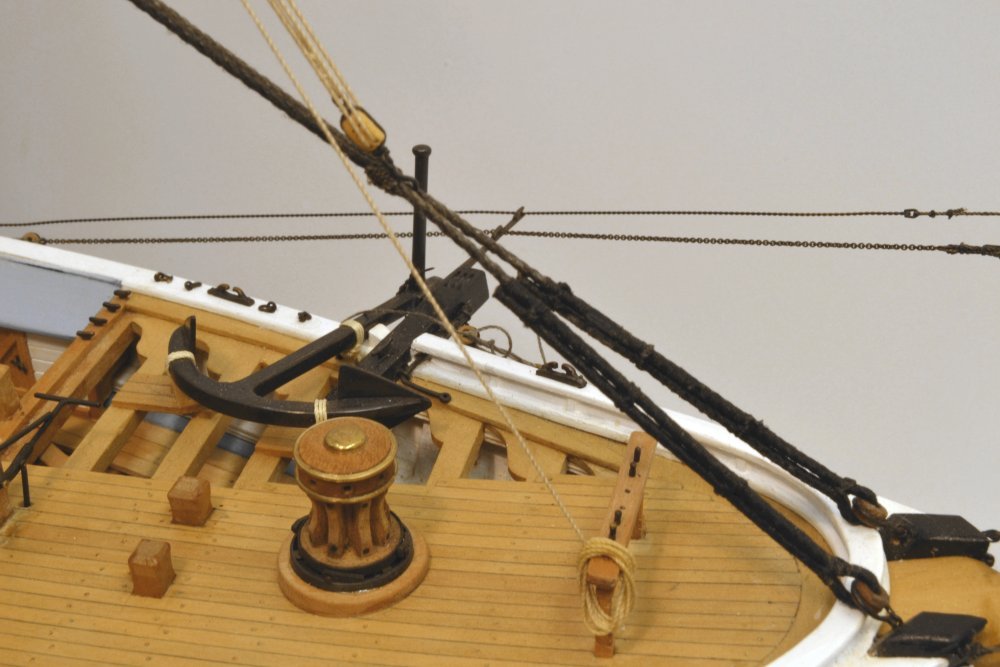
Young America - extreme clipper 1853 Part 236 – Fish Tackle The fish tackle is a triple purchase tackle suspended by a hook from the pendant described in an earlier post. A second, large hook is fastened to the lower block of the tackle. The purpose of this gear is to lift the anchors to stow them on the forecastle or to move them to the catheads. The required weight of anchor for a ship of Young America's tonnage would be about 5000 pounds, so even with the mechanical advantage of 6 of the triple tackle, several hundred pounds of force had to be applied to the lift – unless another tackle was added to the fall. The first picture shows the large bottom hook and the 12" double lower block of the tackle. I still have quite a few blocks left over from the 1:96 Victory model, so with some re-scaling I have not yet had to make any. There will be plenty of that later. The next picture shows the lower block strapped to the hook and being secured to the tackle rope with two seizings. The tackle fall is a 3½" rope spun to the ~1" (.016") diameter from 2 strands of No. 60 Crocheting cotton and dyed with non-fading natural walnut extract stain. The small seizings are simply an overhand knot – pulled tight, wet with glue, and the ends sliced off later. The next picture shows the other hook being strapped to the upper 12" triple block. The block is held in a surgical clamp in a bench vise for this. For this small strapping a single overhand knot simulates the eye seizing at the hook and another overhand knot serves for the splice of the strap under the block as shown in the next picture. Dilute, darkened glue is applied to the splice to fix it. The excess thread is then sliced off. In the next picture the tackle has been rigged. The upper block is hooked to the pendant and the lower end is hooked over a leg the forestay. The fall is belayed and draped for convenience over the forecastle rail – one possible configuration. The next picture shows a closer view. The coil of rope was made separately from a length of line that would be sufficient in using the tackle. Every foot of lift would require hauling six feet of rope. The line was coiled around a dowel, wetted with diluted glue, shaped and allowed to partially dry before mounting. Ed
- 3,618 replies
-
- 32
-
-
- young america
- clipper
- (and 1 more)
-
HMCSS Victoria 1855 by BANYAN - 1:72
EdT replied to BANYAN's topic in - Build logs for subjects built 1851 - 1900
Lovely work, Pat. I like the method of bending the straps back over the tube. You may find that holding a piece of wire in a vise, then clipping the top off just above the jaws will allow you to peen a head on the nail just effectively as using the notched pliers. Ed- 1,013 replies
-
- 4
-
-
- gun dispatch vessel
- victoria
- (and 2 more)
-
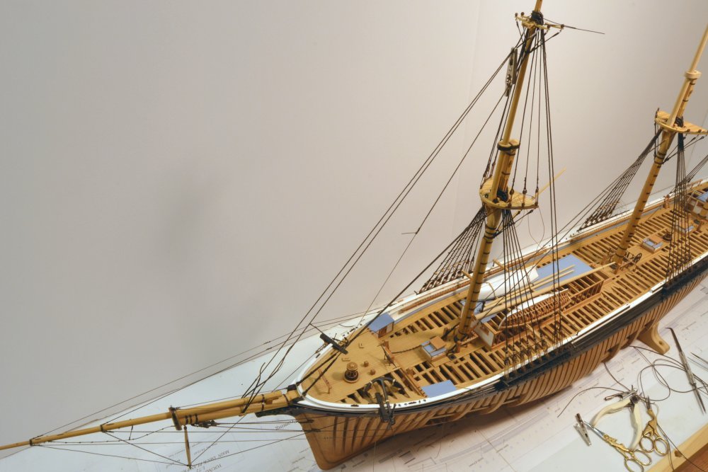
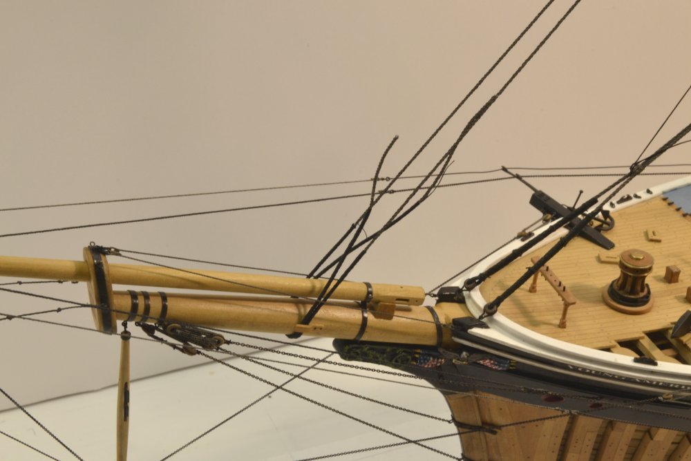
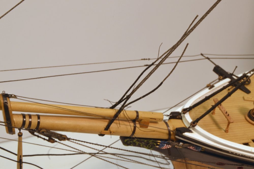
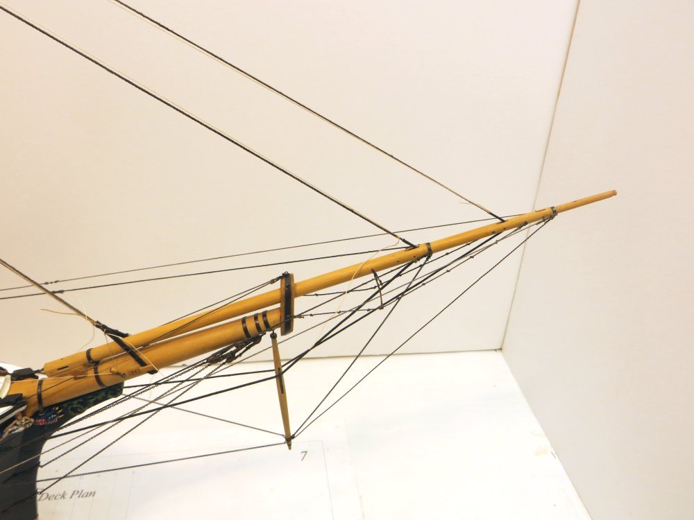
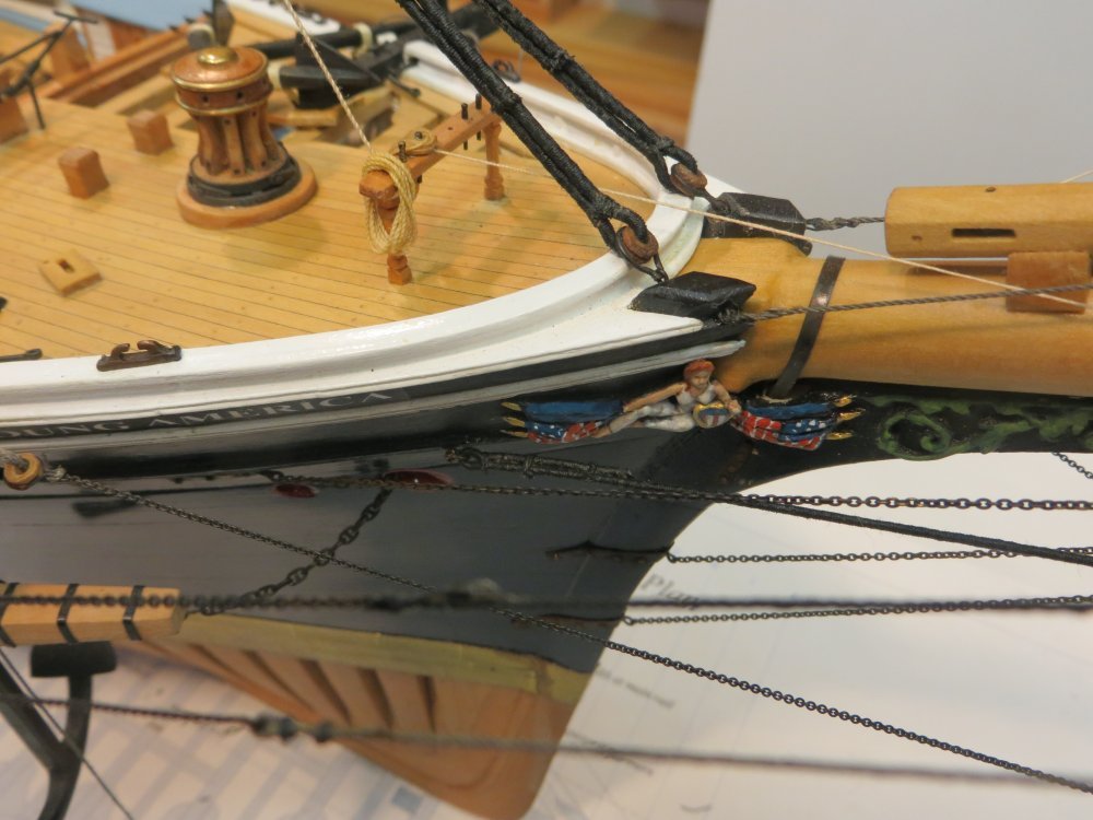
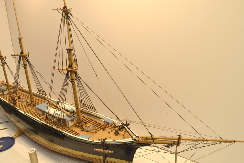
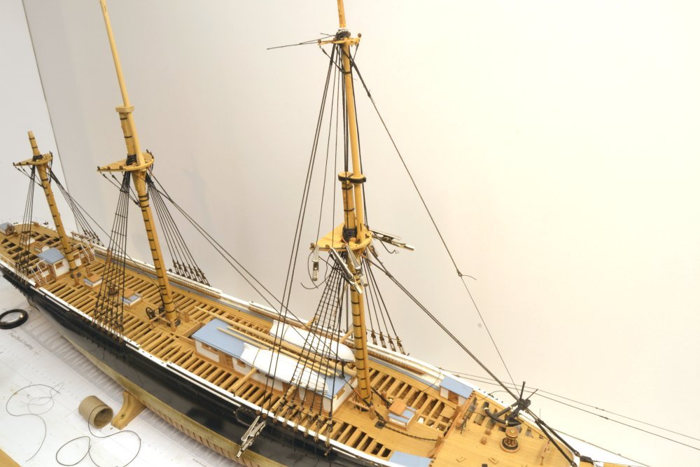
Young America - extreme clipper 1853 Part 235 – Fore Topmast Stays There are three forward stays from the topmast head to the bowsprit – the topmast stay proper, the inner jib stay, and the outer jib stay. The first is the primary structural stay, consisting of a doubled 9" rope looped over the over the shrouds and backstays at the topmast head, then down and under opposite sides of the bowsprit with the ends brought up and seized to the opposite leg. The two lines are brought together to form a collar below the crosstrees and also at the bottom above the seizings. The collar is served and leathered and the lower ends are served on both legs up to the seizings. The first picture shows this stay placed over the masthead after the tissue leathering was glued to it. The collar is clamped where it will be seized together and the glue on the leathering was left to dry in this shape. I used straight PVA white glue for this so when dry the collar will still be flexible. In the next picture, the two legs of the stay have been passed under the bowsprit, in position for seizing. The next picture shows a closer view of the lower area. The two legs do not cross under the bowsprit, so one short leg is seized above the stay and the other below. In the next picture, three seizings have been put on each side and the two legs have been seized together at the top of the served areas. Excess seizing thread and stay rope have yet to be trimmed off. Brushing the seizings and the stay where the ends will be clipped with darkened wood glue will seal the serving and the seizing knots so the excess can be trimmed off. In the next picture the inner and outer jib stays have been served, leathered and put over the masthead and are clamped where the collars will be seized. The leather is simulated on the glued-on tissue strips using acrylic artist's color. The lower ends of these two stays are shown in the next picture. These each pass through sheaves in the bowsprit, under upper cleats on the martingale and are shackled to eyebolts on the hull – the inner jib stay on the starboard side and the outer on the port side. After seizing the upper collars, they were pulled taut through the hull shackles and seized. These stays are served from above the sheaves to their ends at the side. The inner jib stay attachment is shown in the next picture. The stay is seized to a shackle fabricated with its eyebolt before insertion into the hull. These last two pictures and the next were taken after installing the fish tackle and some of the jib/staysail running rigging, so some of this appears in the pictures. Each of these three stays carries a head sail. This work will be described in later posts. The last picture shows the ship with all the forward topmast stays rigged. Ed
- 3,618 replies
-
- 46
-
-
- young america
- clipper
- (and 1 more)
-
Hello Micheal, I am sure practices for setting up rigging varied in the laissez-faire America of the 19th century, so I would be hesitant to debate this. However, all the references I have show the tails at about this length with a total of three seizings - two above the throat seizing. At each stage in the design, questions like this have arisen and have had to be dealt with based on the variety of sources available - and the sometimes diverse answers. Ed
- 3,618 replies
-
- 3
-
-
- young america
- clipper
- (and 1 more)
-
Young America - extreme clipper 1853 Part 234 – Fore Topmast Backstays The four topmast backstays are the same size rope as the lower shrouds, 10½", so the deadeyes and lanyards are also the same sizes. In the first picture, the forward backstay on the port side has its deadeye clamped for turning in. The lanyards are longer for the backstays than for the shrouds, based on photos of the ship, probably to allow more length for tension adjustment of these longer lines. The next picture shows this deadeye turned in with a throat seizing as described earlier. The short leg has been turned up and clamped so the two additional round seizings may be added. In the next picture the aft backstay deadeye height is being set to match the forward stay. In the next picture the lanyards have been threaded and given an initial tension. Final tensioning of all the topmast shrouds and backstays will await the installation of the forward topmast stays. The last picture shows the model after rigging the topmast backstays. The excess stay length on the starboard are not yet trimmed off. In the next part the topmast forward stays will be described. Ed

- 3,618 replies
-
- 35
-
-
- young america
- clipper
- (and 1 more)
-
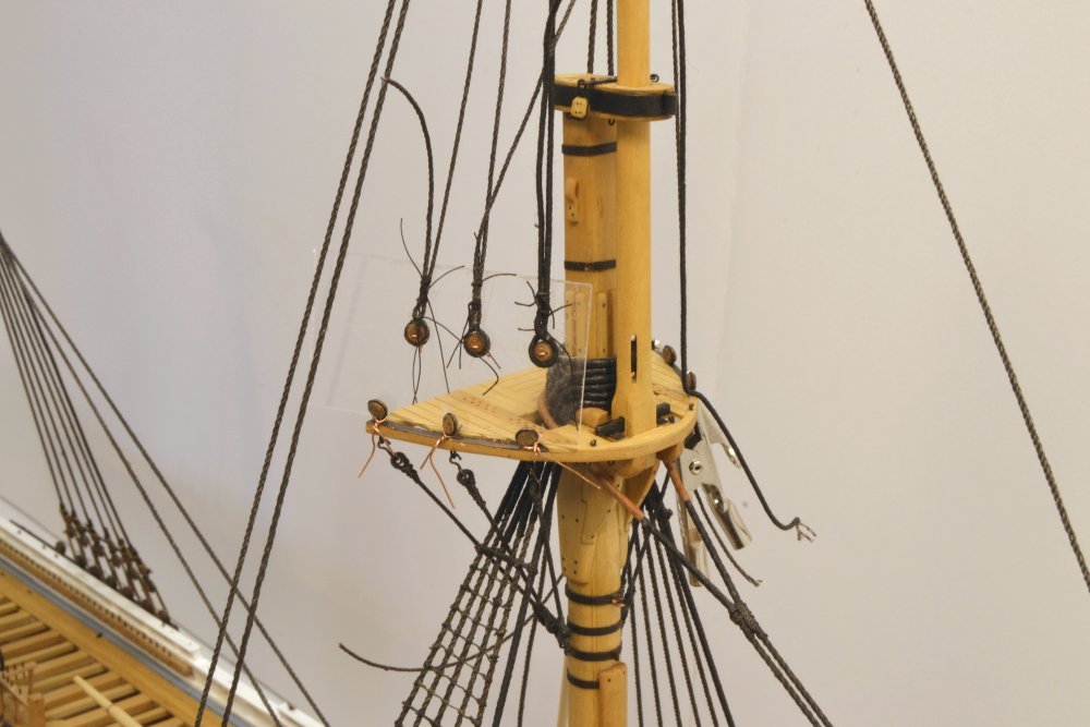
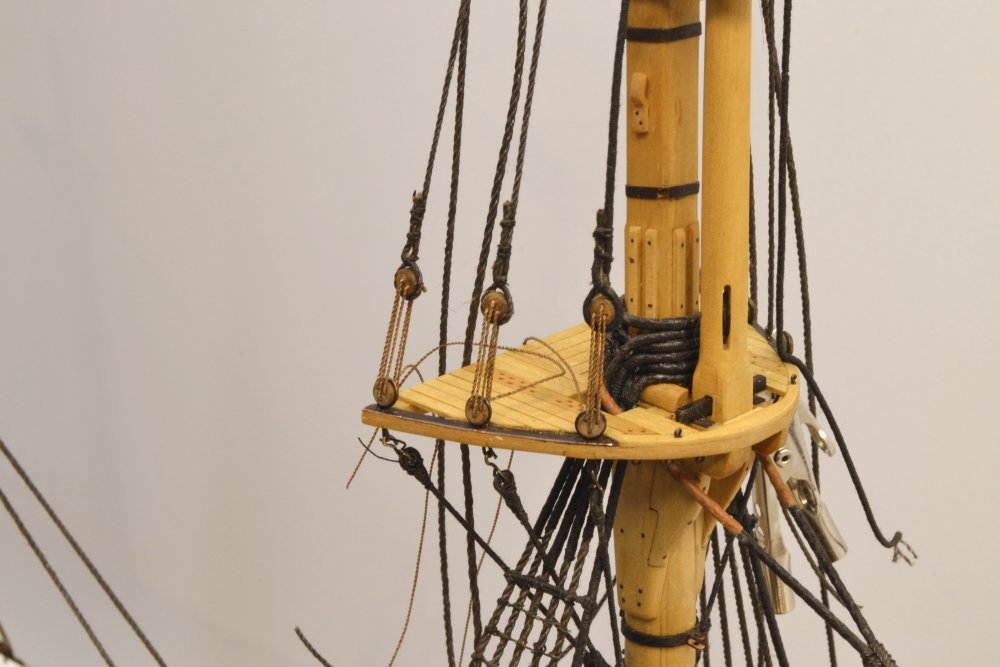
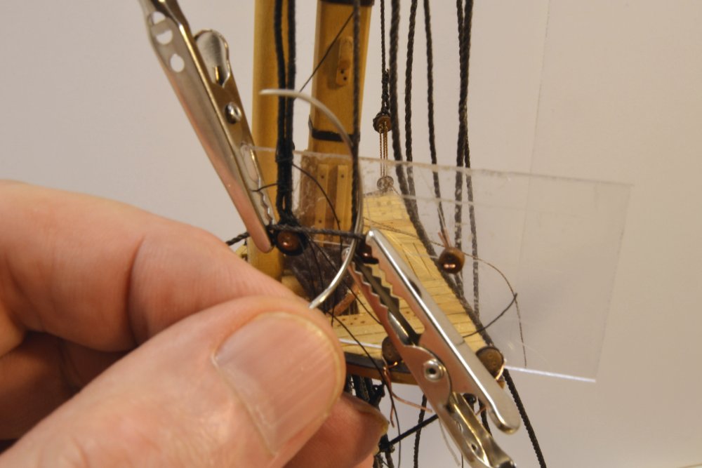
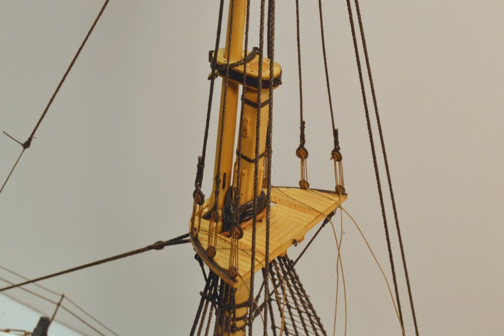
Young America - extreme clipper 1853 Part 233 – Fore Topmast Shrouds In the first picture the three deadeyes for the starboard side have been mounted on a piece of thin clear plastic film and this has been secured to the lower deadeyes at the rim of the top. The somewhat flexible film was used to match the curve of the rim, but this was not really necessary. The fixture is mainly used to align the top deadeyes but is also helps in the "turning in." The three deadeyes have been secured with seizings but the excess thread ends and the excess shroud ends still have to be trimmed off. The next picture shows the three starboard shrouds secured with their 3" lanyards. The lanyards still have to be tensioned and the excess ends wound around the shrouds, but this will wait until the forward topmast stays and the backstays are installed so that all can be tensioned together. The next picture shows one of the deadeyes on the port side being turned in with the first seizing being tied. In the picture a clamp secures the shroud in the groove of the deadeye and another holds the short leg horizontal and tight. A curved needle is being used to help make the throat seizing that was used just above each deadeye. In this type of seizing the thread is wrapped over the crossing of the shroud, so the needle is passing through the opening above the deadeye under the front horizontal leg and behind the vertical leg. This is then repeated and the last pass secured with a clove type finish. The short end of the shroud is then brought up to vertical and secured to the shroud with two more round seizings on the parallel legs. The next picture shows all six shrouds secured to the top. Finally, a picture of the model with the topmast shrouds and backstays secured. The fish tackle pendant is still temporarily tied off at its lower end. The backstays will be described in the next part. Ed
- 3,618 replies
-
- 39
-
-
- young america
- clipper
- (and 1 more)
-
Thank you all for these comments - and Kevin, my hat is off to you for perseverance if you REREAD all 230+ parts. I think my eyes would glaze over early in such an effort. But thank you for your interest. GM02, your comments are more than generous. When I started this project, I knew I was biting off a lot, but big, complex projects attract me. It has been four years so far in construction and several months before that in getting a critical mass of early drawings together. Since I have built relatively few ship models - three including this one - this is still an exploratory effort for me. There are often fits and starts, but when something works, I am pleased to share it. I very much appreciate your comments on the iron fid. When I first realized the size of it from the Crothers drawings, and the weight implications, I was taken aback and skeptical. Further research (Fincham, Mast-Making, 1843) confirmed the sizing - 1/3 the mast diameter in depth for an iron fid, 1/2 for wood and 2/3 width to depth ratio. It is one big chunk of iron. As far as rigging and handling this, I do not believe riggers of the time would be too challenged. Even with the absence of end holes in these lower fids - the upper mast fids have holes in the ends for standing lift shackles - I believe the fid could be lifted with a sling secured at the ends and then pushed or hauled through the hole before lowering the mast on to the trestle trees. This would be like a toothpick compared to the 82', 22" diameter fore yard loaded with all its ironwork - to say nothing of the larger main yard. We often tend to underestimate the capabilities of this earlier time. Thanks again for the comments. Ed
- 3,618 replies
-
- 6
-
-
- young america
- clipper
- (and 1 more)
-
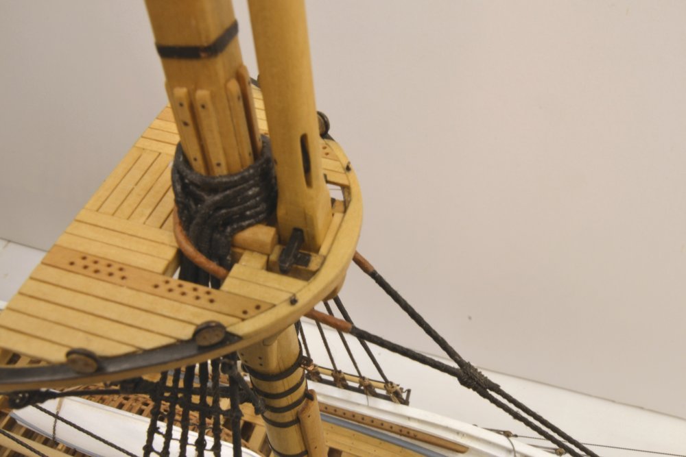
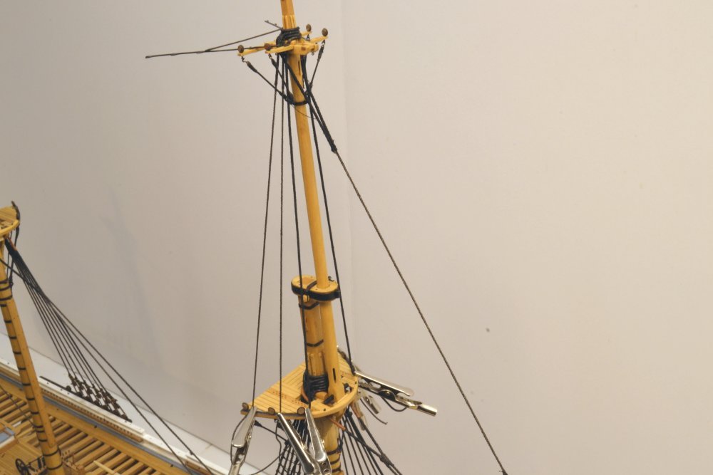
Young America - extreme clipper 1853 Part 232 – Fore Topmast Crosstrees 3 The first picture shows one of the fore topgallant futtock shrouds being lashed to the band below the fore topmast crosstrees. Although they are fitted to the topmast, these shrouds are part of the topgallant shrouds above – hence the somewhat confusing naming. Each lashing is first tied to the eye, then passed through the eyebolt and eye three times, and then wrapped around itself in the center with a series of clove hitches. The clove hitches are an effective way to do this on these small lashings – and easier than wrapping a lot of turns while trying to keep the lashing from rotating while still making the turns tight. The difference is virtually undetectable on these small black lashings. The next picture shows the four futtock shrouds lashed in place. With these installed the topmast may be permanently fitted. The next picture shows the lower end of the installed mast. The mast fid is down on the iron plates and a filler piece has been fitted at the forward face to fix the bottom and keep the mast aligned. Although not strictly necessary, the mast was glued at this point and at the cap. The first piece of rigging to go over the mast is the fish tackle pendant. This long pendant was used to suspend the triple purchase tackle that was used to lift and handle the anchors. The pendant is therefore a heavy 8" rope. It is served around the seized masthead collar. The lower end has an eye splice with a thimble at its foot The large upper block of the tackle will be hooked through this thimble. In the picture the pendant is temporarily held taught by some black thread. After the fish tackle, the topmast shrouds are put over the masthead. In the next picture the shrouds have been placed and held at the foretop with clamps. As with the lower shrouds the forward shrouds are fully served. Serving on the others extends around the mast to just below the futtock shrouds. The two forward shrouds are a single line that loops over the mast and is seized below the bolsters. The aft shrouds are single, with a single eye splice served down to the futtock shrouds. All these collars and eyes are parceled down to the seizings. The next picture shows a closer view of this. Next to go over are the topmast backstays, a pair on each side. The collars of these are also served and parceled down to the collar seizings. They are clamped at the channels in the next picture. These are large 10½" lines, a looped pair on each side. The last picture shows the parceling of these before the parceling is "tarred" with black artist's acrylic paint. They were removed for this painting after tying the seizings. With all these lines secured at the top, the next step is to fix them to their deadeyes at the lower ends. Ed
- 3,618 replies
-
- 29
-
-
- young america
- clipper
- (and 1 more)
-
Pat, The padding in the vise is just a small piece of foam carpet padding. Ed
- 3,618 replies
-
- 4
-
-
- young america
- clipper
- (and 1 more)
-
Hi Pat, The holes are drilled to just pass the lower loop on the strap - with just a bit of enlarging with a small tapered reamer if necessary to push them through.
- 3,618 replies
-
- 3
-
-
- young america
- clipper
- (and 1 more)
-
Wefalck, I am certainly open to suggestions to trim down the shape of the splice. I have tried a number of different methods and have some others in mind. The bumps on the splice are mainly the product of roughness in cutting back the short leg, serving over the previously served part, and knots in the rather large serving thread. One approach might be to "plasticize" the area of the splice to fuse the rope and serving - well enough to allow this to be trimmed into the serving on the standing leg without having it unravel, then serve over this slimmed down, smooth part after the splice is glued. I plan to try this on the next set. The approach you describe is well worth a try. There might be some measurement issues on the second end and there is also the issue of serving a short rope with eyes at both ends. I like the idea of having the rope pre-served for these reasons and because it eliminates setups on the serving machine. But still worth a try. Frank, after filling the clip jaws with epoxy compound, a waxed pin can be used between the jaws to form the round. Waxed paper between the jaws is necessary to prevent their bonding. Alligator clips are inexpensive and can be modified to meet a variety of needs. They are also light enough to use in rigging. Ed
- 3,618 replies
-
- 4
-
-
- young america
- clipper
- (and 1 more)
-
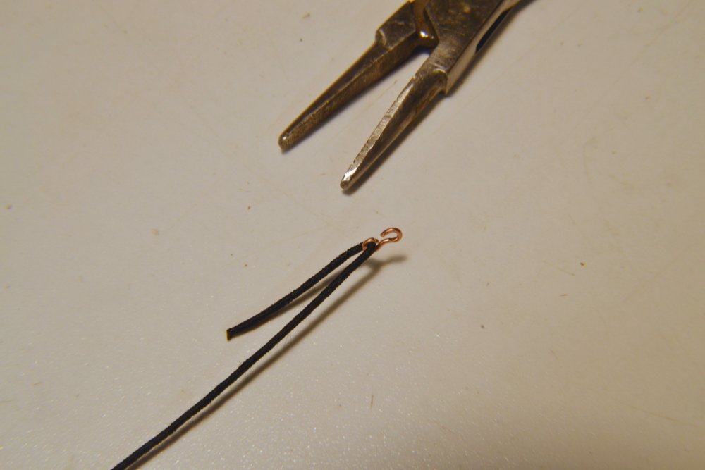
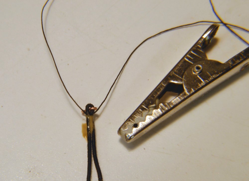
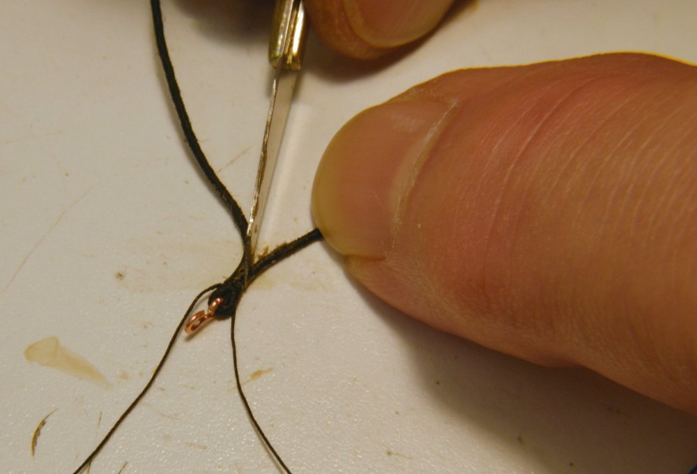
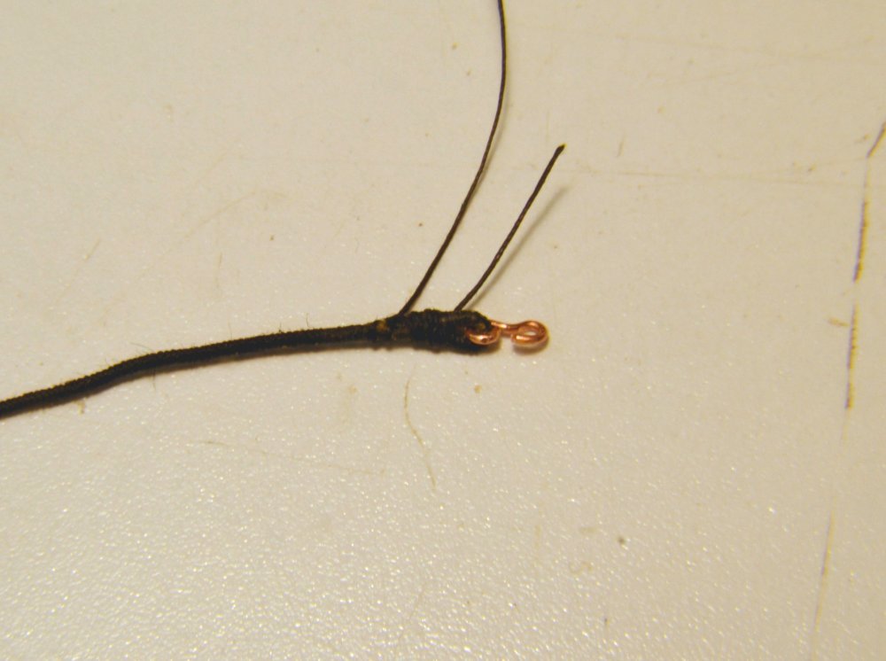
Young America - extreme clipper 1853 Part 231 – Fore Topmast Crosstrees 2 After the last post, I explained the drawing revisions at the foot of the fore topmast, specifically the dimensioning of the square heeling. The first picture shows this part of the mast positioned on the trestle trees of the fore top. The bottom of the topmast is about 1" lower than the lower faces of the 18" deep trestle trees when the fid is down on the top faces. The height of the sheave is not a critical dimension, but must be above the square section so the hoisting line will pass inside the square opening when the mast is raised. One of the eyebolts on the underside of the cap would have been used to support the lifting tackle. In the next picture the crosstrees have been permanently attached to the mast and the four deadeyes for the topgallant shrouds have been fitted but not yet blackened. These 8" deadeyes will secure the 5" shrouds above and the same-sized topgallant futtock shrouds below. The naming of these futtock shrouds that are installed as part of the topmast is a constant source of confusion to me, but I think I have finally cemented it into my mind. In the next picture the deadeye straps have been blackened and the masthead has been fitted with its trim. The battens are very small and will be covered by the rigging collars. The cleats on either side will support a bullseye for the main royal stay. Before installing the topmast, the topgallant futtock shrouds were installed. As with those under the top, these are hooked through the deadeye straps at the top and lashed to eyebolts in the futtock band at their feet. I have attached some pictures showing the method I am using to form the eye splices in the served shrouds. In the first picture a small hook has been formed and threaded with the served 5" line. The serving at the end is kept from unraveling with a drop of CA. I am trying to limit the use of CA to non-permanent applications like this - except for the attachment of metal parts, like eyebolts, to wood. The line was then seized at the throat of the splice with fine cotton thread with a tight overhand knot. In the next picture darkened wood glue has been applied in the area of the splice. The glued area was first wetted to help the glue penetrate through the serving. The glue joint was then clamped with the modified alligator clamp shown in the picture The jaws of this clamp have been filled with epoxy sculpting material to form a round clamping hole shown between the jaws. When the glue has dried the excess rope was cut from the joint with a sharp knife as shown in the next picture. The cut is made to form the taper of the splice. The purpose of the glue is only to hold the joint together to allow wrapping of serving down to the bottom of the splice. The glued serving will hold the splice together. The finished splice is shown in the next picture. Finishing with a smoothly tapered splice at this scale can be a challenge, but after glue is applied to seal the added serving, some crimping may be done to eliminate bumps. Removing the excess serving without leaving short stubs is also a challenge. This is done after the glue dries. In the next picture the hook has been blackened and temporarily fitted to its strap so the length to the eye at the other end may be measured as shown in the picture. An eye is formed at the lower end by the same method but without the hook. The lashing of these lower ends will be described in the next part. Ed
- 3,618 replies
-
- 39
-
-
- young america
- clipper
- (and 1 more)
-
Thank you, Piet. The method used for fastening ratlines is interesting. Riggers faced the same problem we do as modelers trying to duplicate the method. How long does each ratline rope have to be to come out at the right length after tying the intermediate clove hitches? I solve the problem by making the last eye splice in place, but I doubt that would be done in actual practice. It seems that there was a practice to account for over-length lines. The last end would be wrapped a few turns around the outer shroud. No comment on what to do with the short ones. Use them further up, I guess. Ed
- 3,618 replies
-
- 4
-
-
- young america
- clipper
- (and 1 more)
-
I am sure the cutter would work fine on boxwood (or the common replacement, Castello) but I wonder about the milling speed for a single cutter bit. What milling speed was used? Ed
-
Thank you, Karl - and thank you Piet for your 18 likes. Ed
- 3,618 replies
-
- 1
-
-
- young america
- clipper
- (and 1 more)
-
Thank you for all these comments and, of course, for the likes as well. Your concerns for the fate of the flimsy spreaders at my often clumsy hands is well appreciated - and well justified! They have already been straightened a few times. Druxey I may well try your suggestion once the topmast is secured. Right now it is off for the rigging of the futtock shrouds, but will soon be in place permanently. Pat, I share your concern, but only time will tell. I am hoping that the stays will not be taken off their line too far and cause excessive inward pressure on the spreader. We'll see. I am somewhat confident that if the actual spreaders could handle it these should as well. Wishful thinking, perhaps. Ed
- 3,618 replies
-
- 6
-
-
- young america
- clipper
- (and 1 more)
-
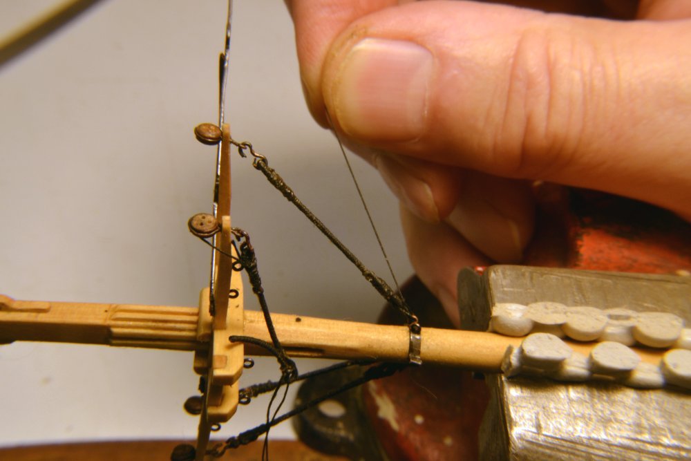
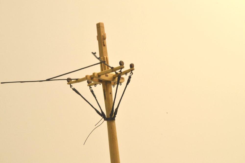
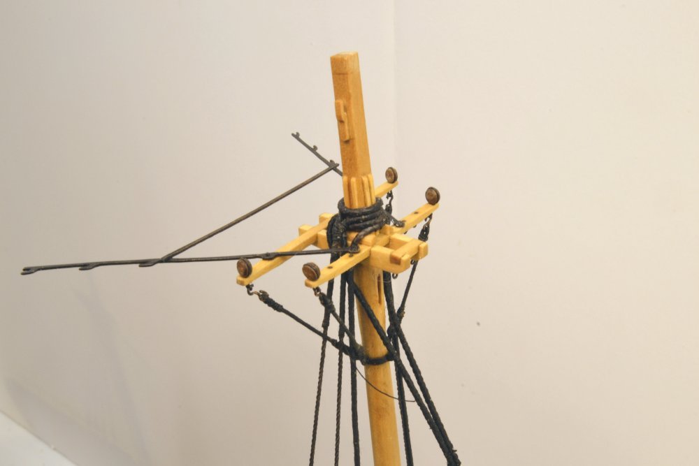
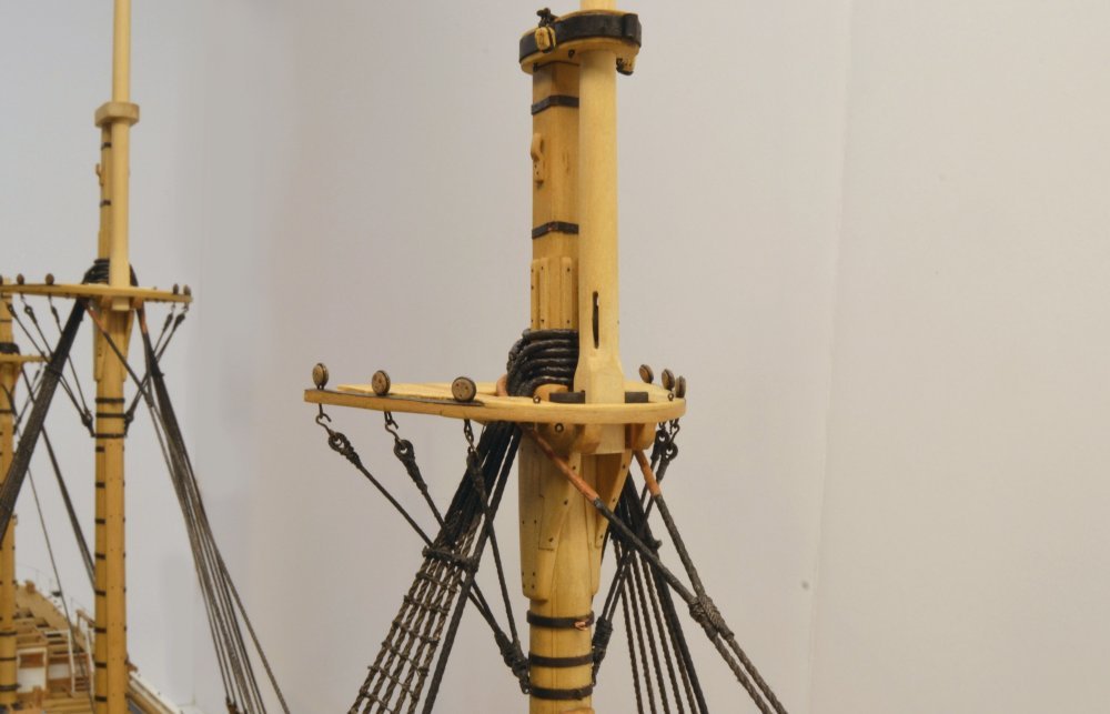
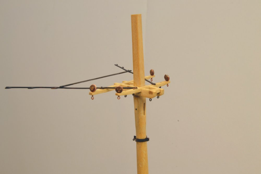
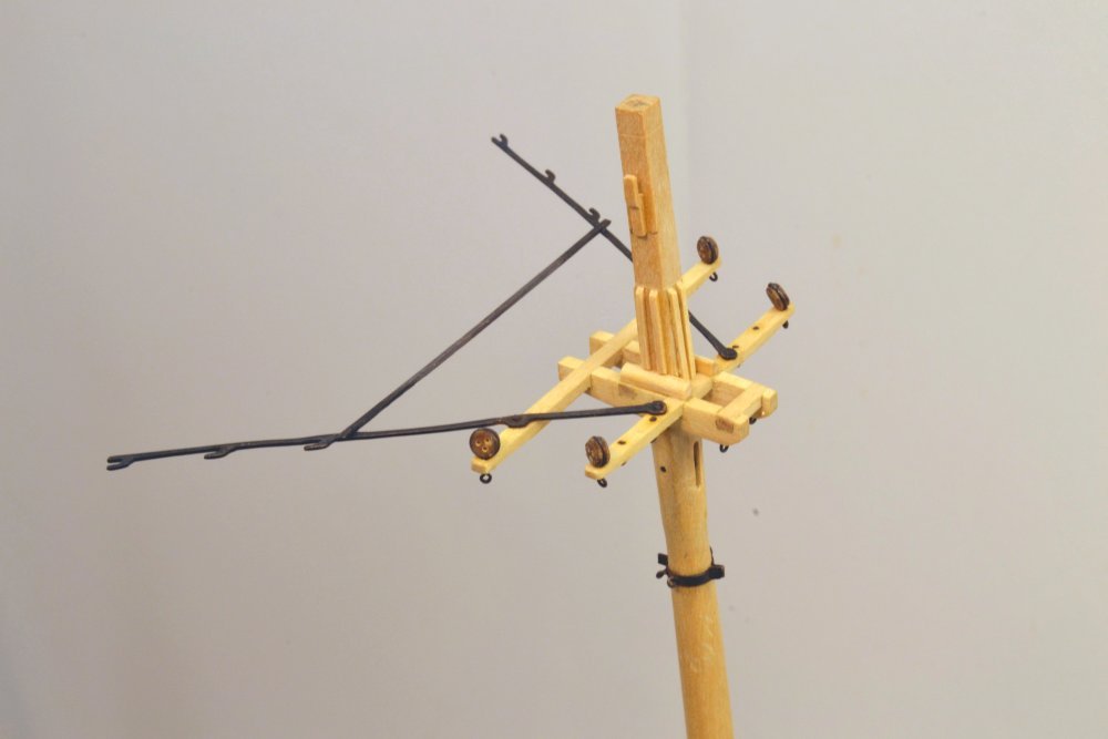
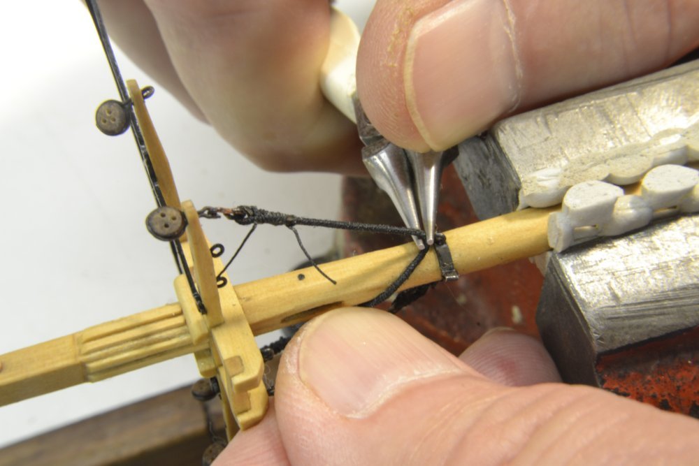
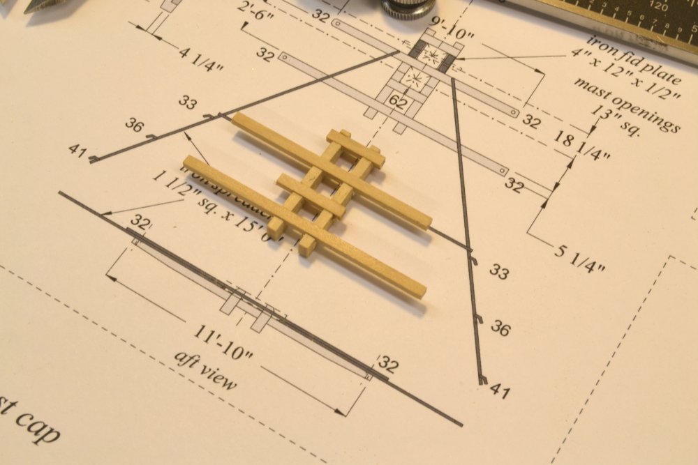
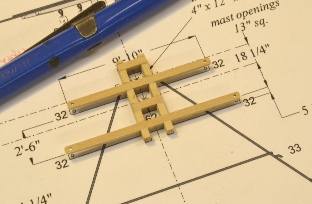
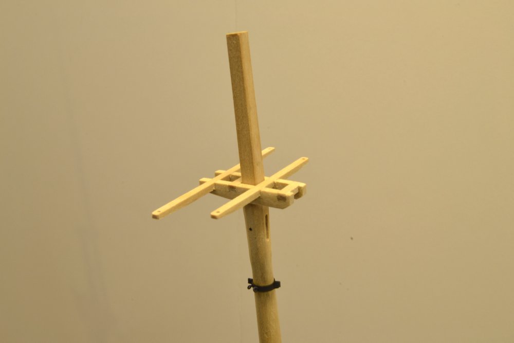
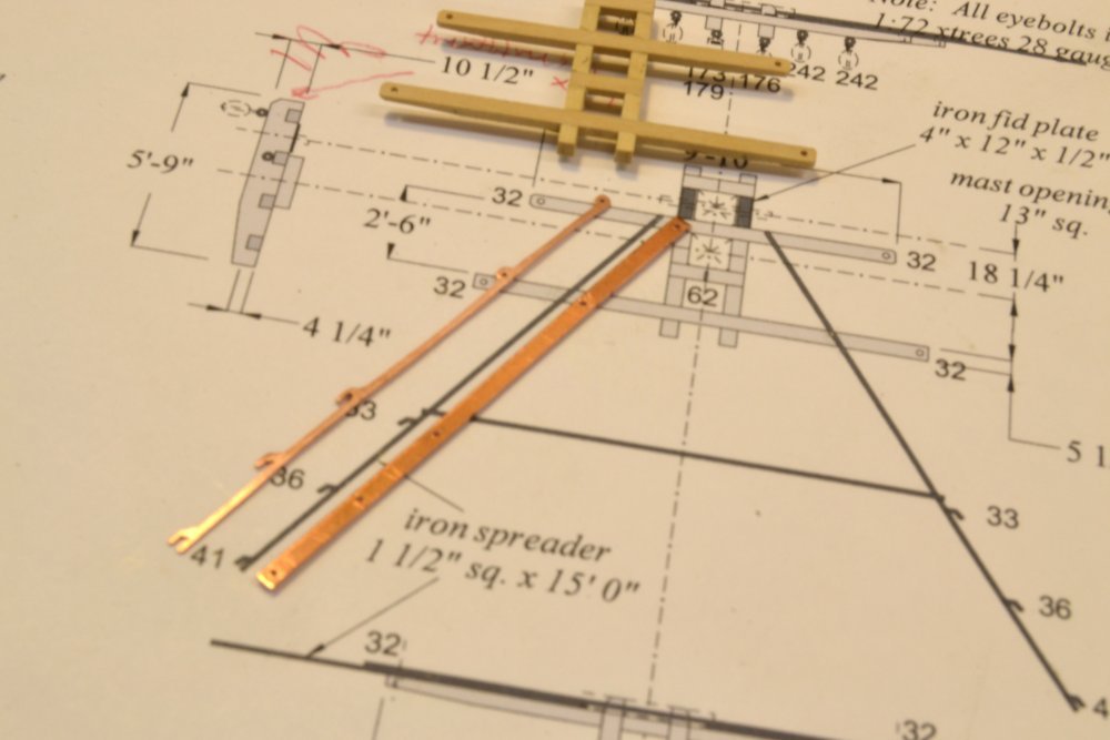
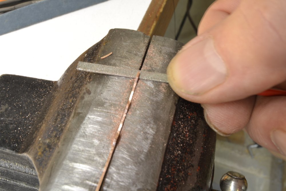
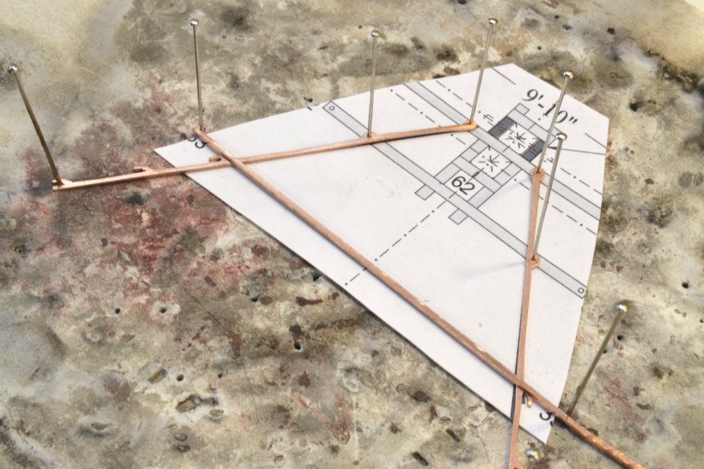
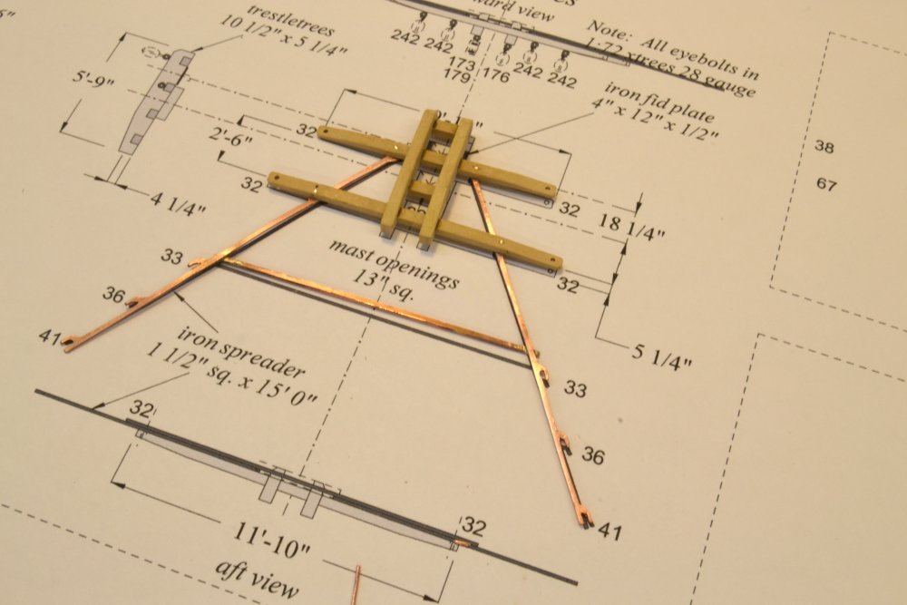
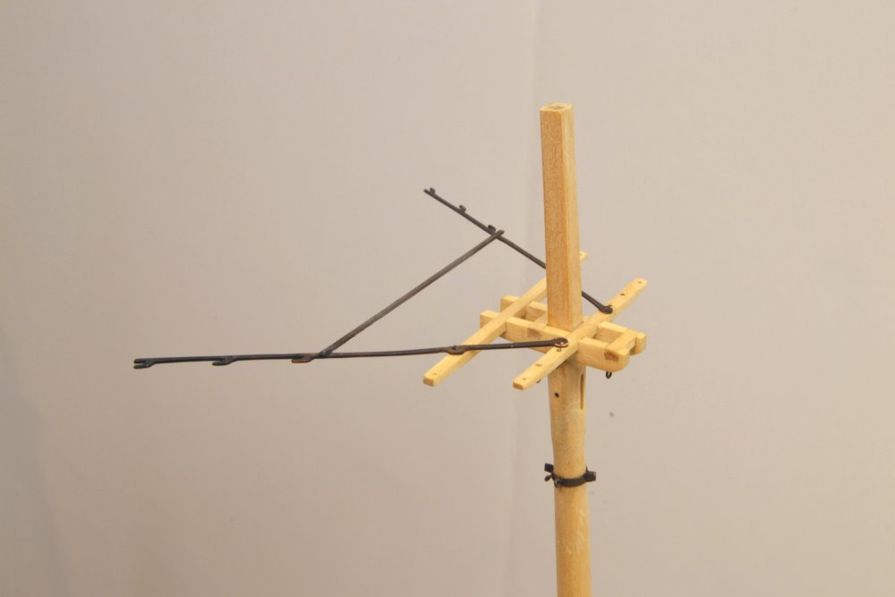
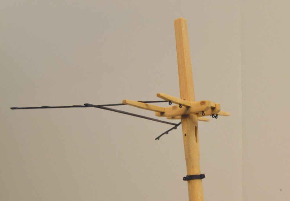
Young America - extreme clipper 1853 Part 230 – Fore Topmast Crosstrees The topmast crosstrees are fairly simple structures – except for the iron spreader assembly that mounts fairleads for the backstays of the masts above. In the first picture, the members of the wooden structure are shown fitted together but not yet trimmed to size. The four athwartship members are set into mortises in the fore-and-aft trestle trees. The drawing (almost complete) shows the arrangement of the spreader irons. In the next picture the wood structure has been assembled, drilled for the deadeye straps, and the arms tapered. The next picture shows the assembly positioned on the topmast. In the next picture, one of the spreader arms has been roughly shaped and the second has been drilled before shaping. The spreader structure was made from .020" hard copper plate for stiffness. It will be very fragile nonetheless. The assembly will be bolted to the crosstrees through the two forward holes (that do not yet appear on the drawing). Holes drilled in the unshaped piece on the outer arm will help precisely locate the fairlead cleats. The next picture shows some shaping of the cleats. Before filing the final shapes, the profile was cut out with a jeweler's saw. In the next picture, a drawing scrap is being used to place the arms and cross piece for soldering. After pinning, the paper was removed and the two joints soldered with minimal heat to limit the softening of the copper strips. In the next picture the spreader assembly has been cleaned up and bolted to the crosstrees. The bolts are copper wire pushed through the holes and riveted. The next picture shows the crosstrees assembly placed on the hounds. The last step was to add the eyebolts on the underside of the structure. In this picture the assembly has been permanently attached to the topmast. I am hopeful that the fragile spreader structure will gain some support after the stays are rigged through the fairlead cleats.Further work may now proceed on the detailing of the topmast head and fitting deadeyes the the assembly. Ed
- 3,618 replies
-
- 38
-
-
- young america
- clipper
- (and 1 more)
-
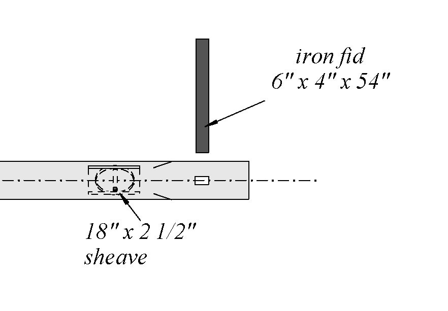
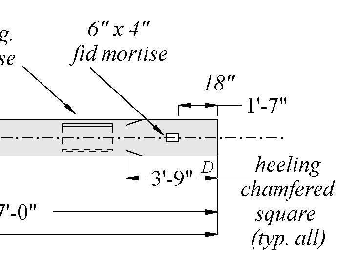
Hi Micheal, You have noticed another case of my taking pictures with discrepancies between the drawings and the work. My apologies to all for these differences. They occur when I elect not to print the latest revision for use in the shop - a very bad practice, but one I reluctantly sometimes adopt in the interest of saving 11 x 17 printer paper and ink. Unlike the recipients of my final drawings, I am usually doing drawing revisions "just-in-time" for construction because before constructing something I usually go back and make sure my best current data is reflected on the drawings. In this case the dimensioned construction drawing for the spar had been updated and printed for use in making the spar correctly, but not the mast detail sheet which was still undergoing revision - mainly for upper mast details like rigging line numbers. Snippets from the current detail drawing and spar construction are shown below. You will note the difference from the first two drawings in the post above. The square heeling has been shortened to correct size (2.5 X mast diameter) and the location of the fid hole updated based on the final drawing of the top. The bottom of the hole is 1" + the depth of the trestle trees above the mast bottom. These dimensions are shown on the spar construction drawings but not on the detail sheets. Again sorry for this confusion. I should be more careful or at least note when these differences occur. Thanks, Micheal. I like it when people look closely. Ed
- 3,618 replies
-
- 15
-
-
- young america
- clipper
- (and 1 more)
-
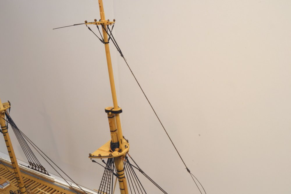
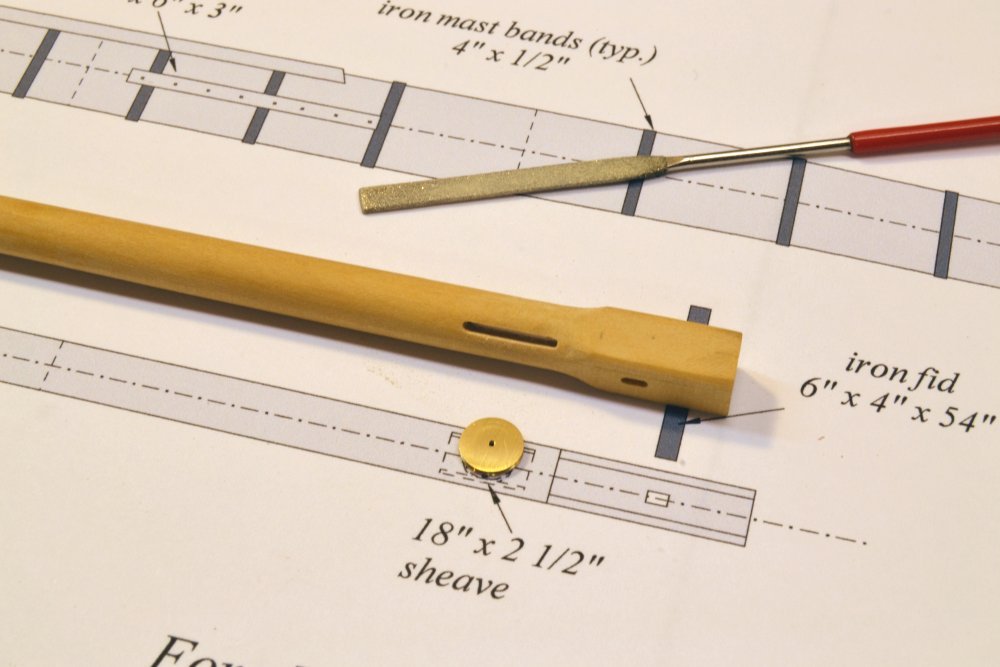
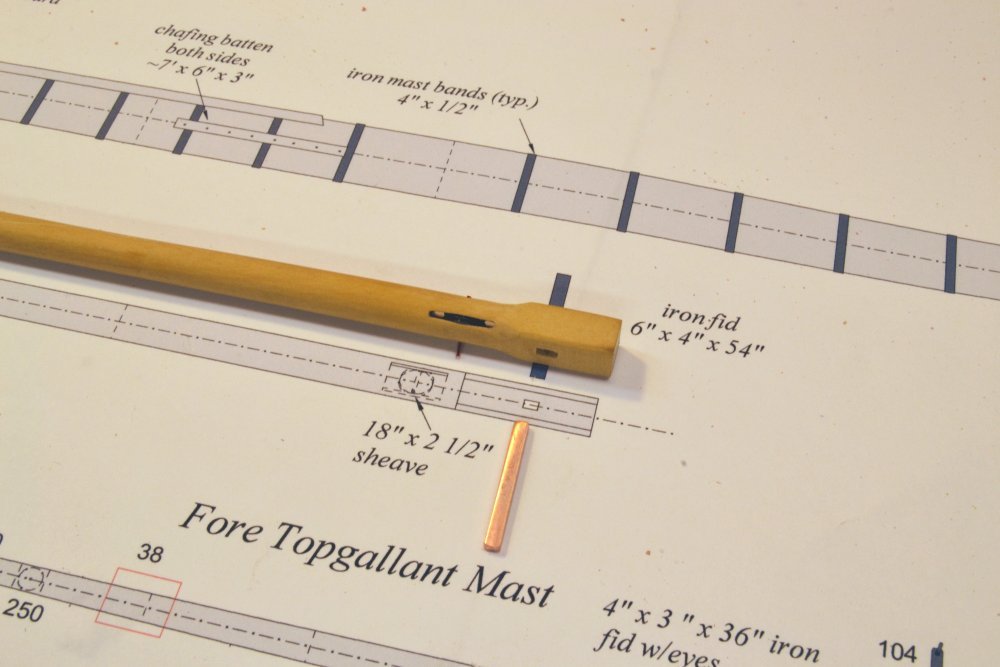
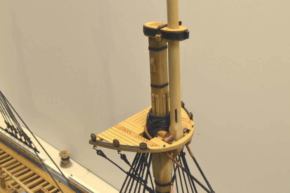
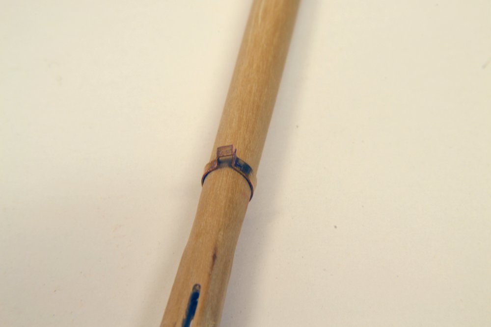
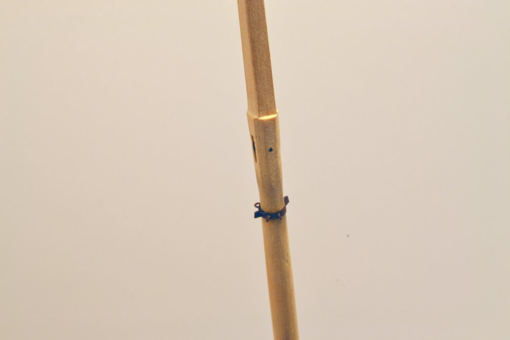
Young America - extreme clipper 1853 Part 229 – Fore Topmast 2 The first stages in making the fore topmast were described in Part 226. There are just a few details to be added in this part. The first picture shows the lower sheave ready to be installed. All slots through the mast were cut with a 1/32" milling cutter, so in most cases some enlargement is required to accommodate other parts. Slight enlargement of this sheave opening was done with the small diamond grit file in the picture to widen the slot to a scale 3". The 2½" thick sheave with a diameter equal to the mast at its position was turned in brass on the lathe. This sheave was used to raise the mast by means of a tackle hooked to the foremast cap. The sheave is angled on the mast so the that rope will clear the close, square opening in the fore top. The next picture shows the topmast fid. The dimensions of this substantial piece of iron may be seen in the photo. The slot for this piece was also widened with a small file. The next picture shows the lower end of the topmast temporarily in position. In practice the topmast would be raised up through the opening in the top and through the cap from below. The mast would then be fitted with the futtock band and the crosstrees. On the model the topmast will be slipped through the cap only, then fitted with the upper details including futtock shrouds. Then the whole assembly will be set in place from above. Because the futtock band will not fit through the cap, it was installed after the cap was slipped over the mast. The method for fixing the band is shown in the next picture. The band is placed below the hounds, which flare out to seat the crosstrees, so it cannot be pre-made and slipped over. The tab shown in the picture was crimped to hold the band and also to simulate the bolted, clamping flange that would have been used. Obviously this piece could not be soldered. The band will be fixed to its position when the four futtock shroud eyebolts are added through holes drilled in the band and into the mast. The completed band and eyebolts are shown in the next picture. The picture also shows the sheave for the upper topsail halyard tie installed, as well as the seat at the top of the hounds for the crosstrees. Those crosstrees will be described in the next part. Work on these mast parts has been interspersed with "rattling down" of the lower shrouds. The last picture shows this work completed on the starboard side of the fore mast. Ed

- 3,618 replies
-
- 31
-
-
- young america
- clipper
- (and 1 more)