


EdT
-
Posts
2,214 -
Joined
-
Last visited
Content Type
Profiles
Forums
Gallery
Events
Everything posted by EdT
-
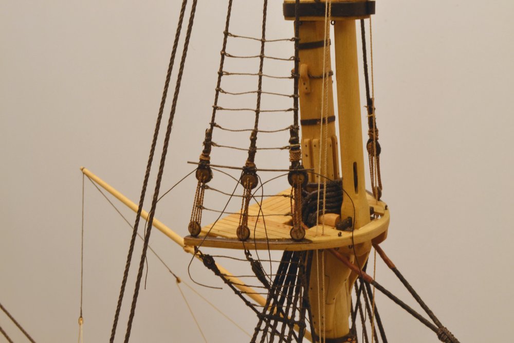
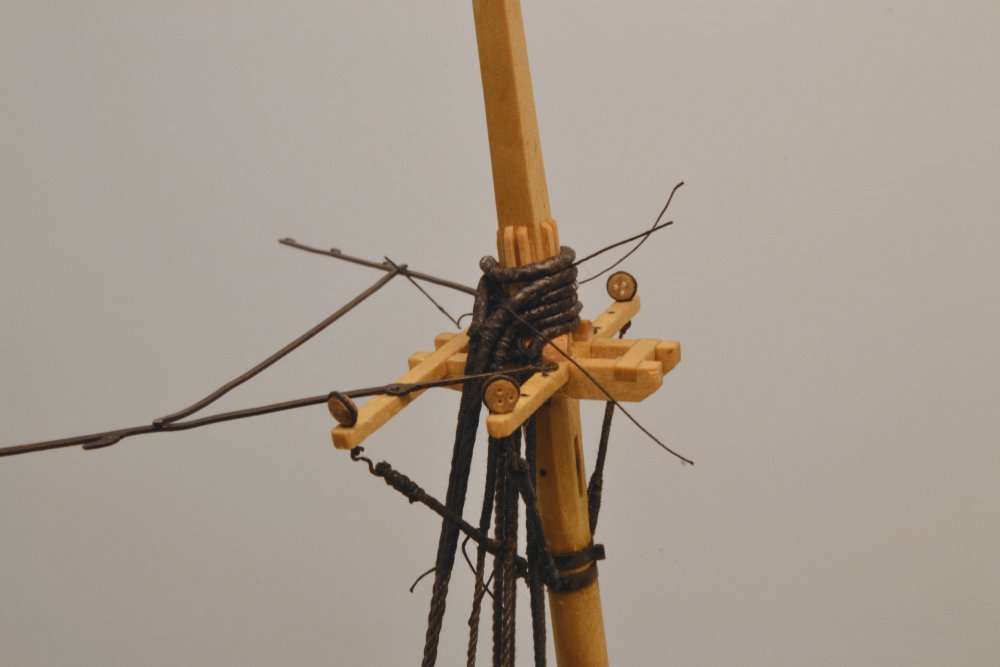
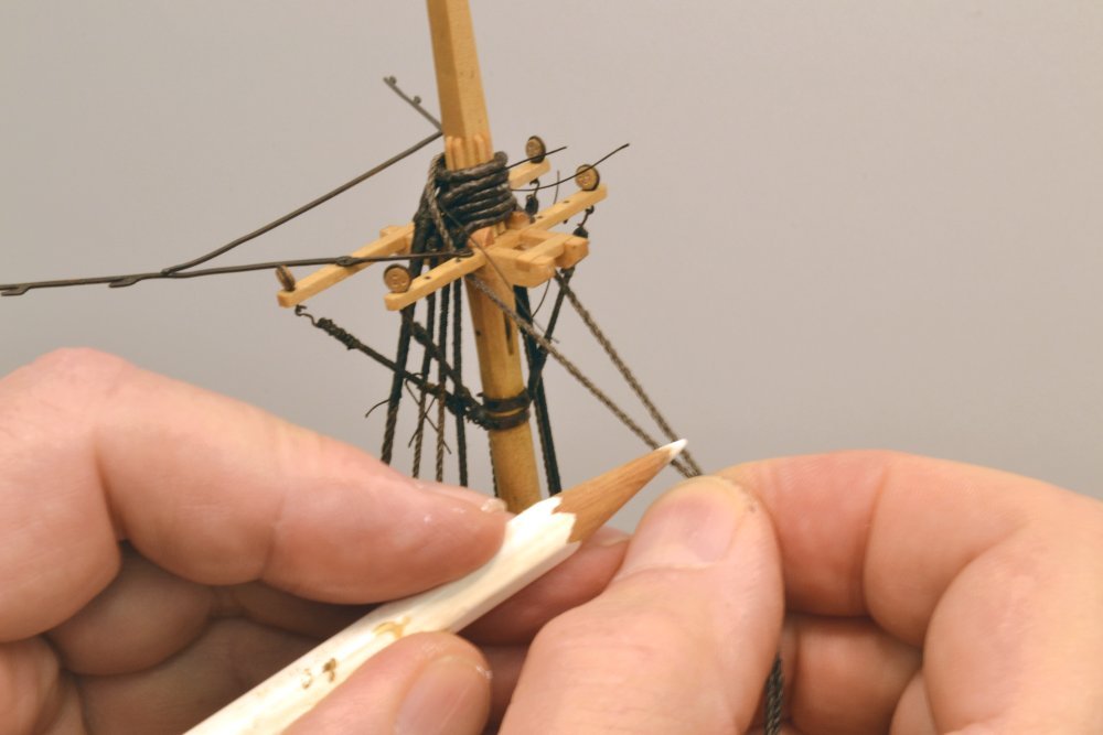
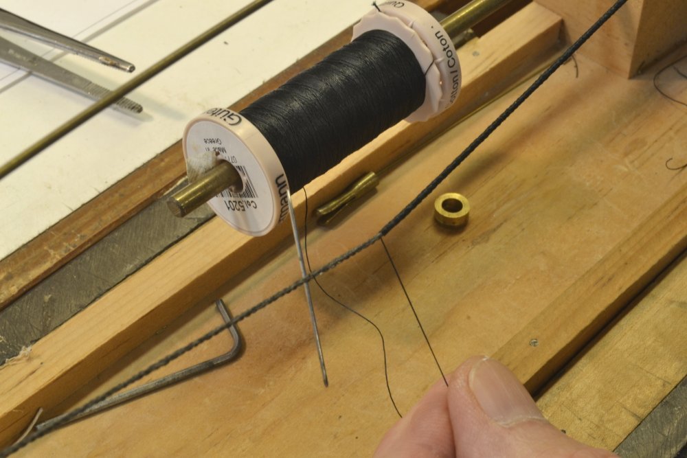
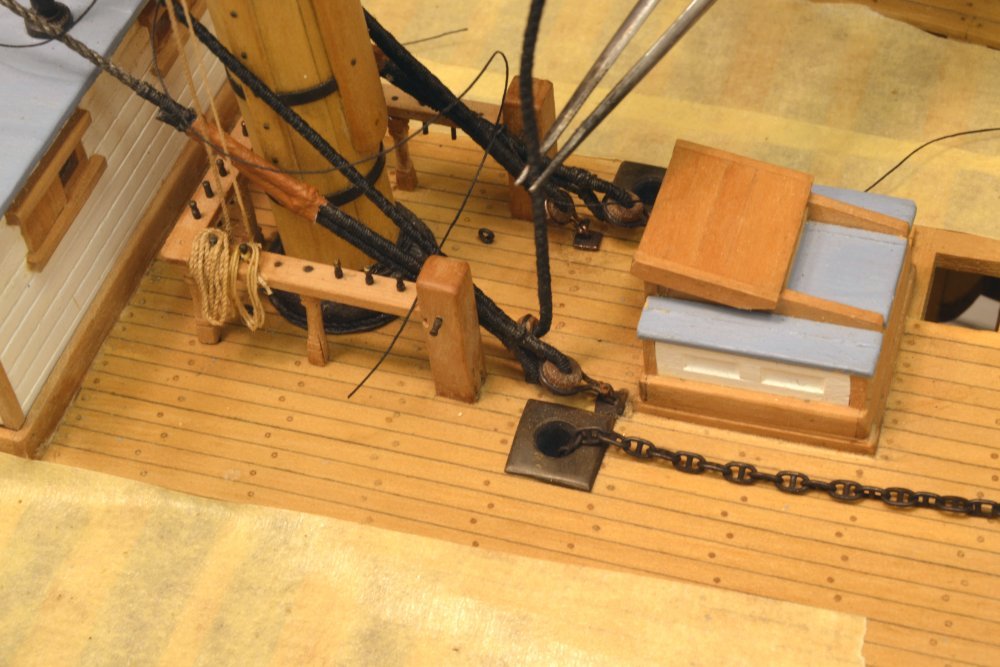
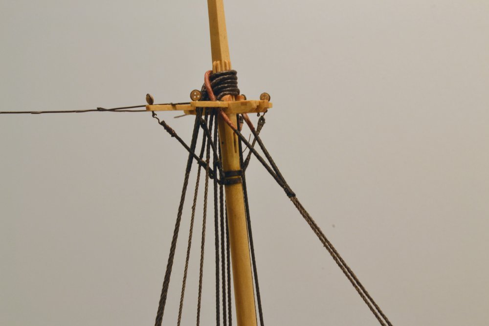
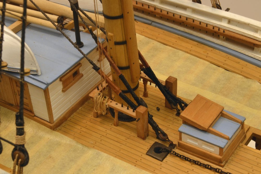
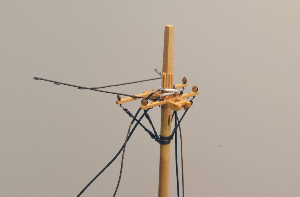
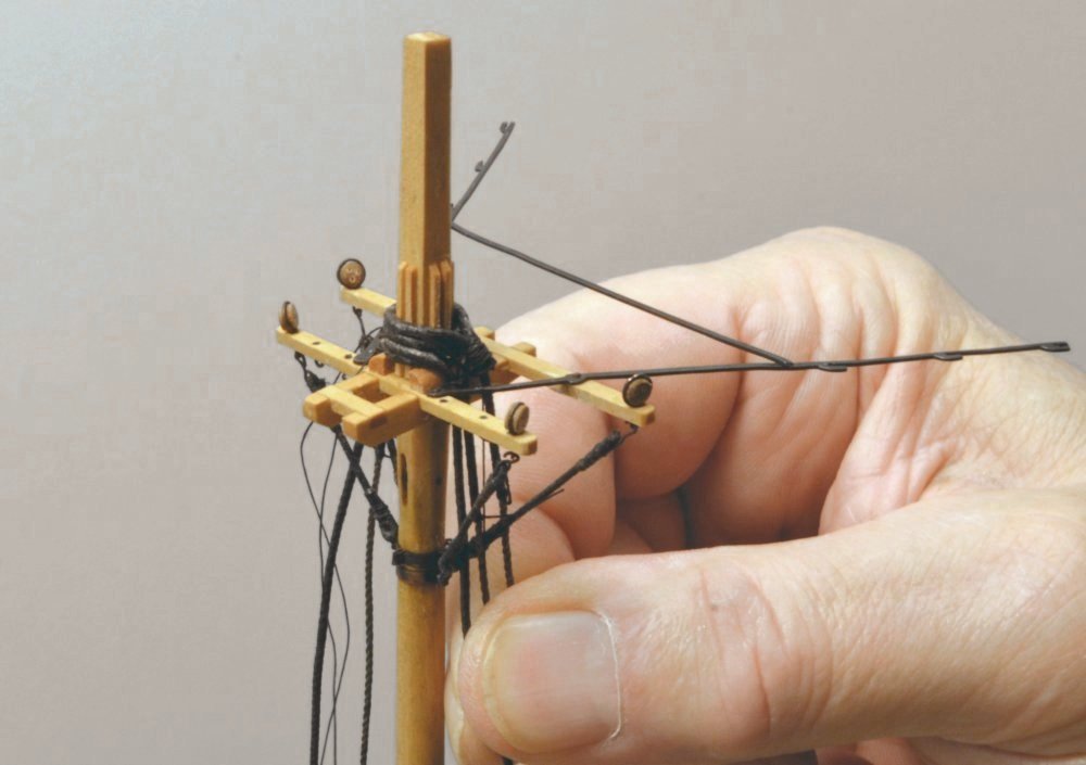
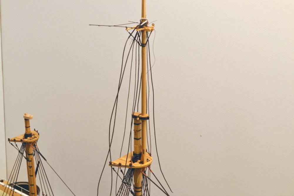
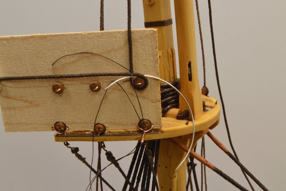
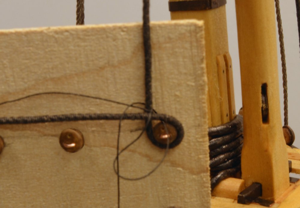
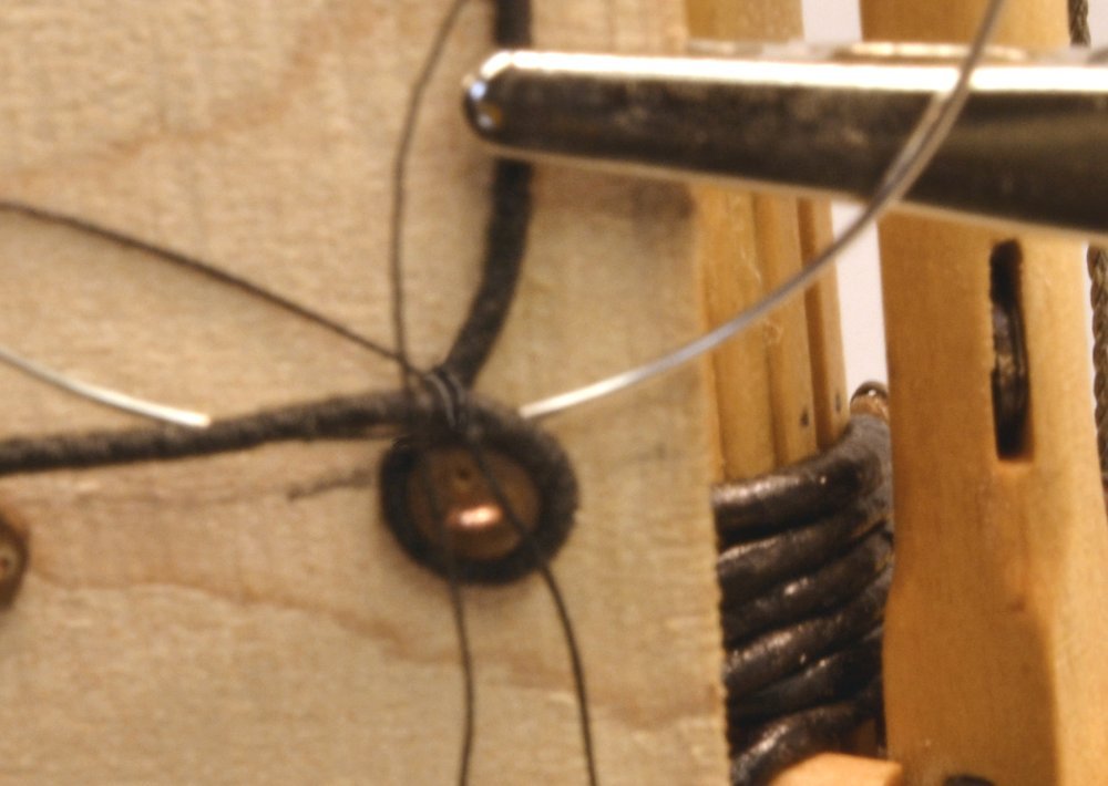
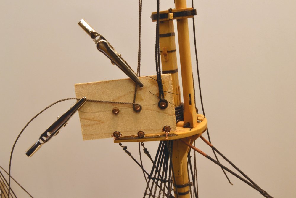
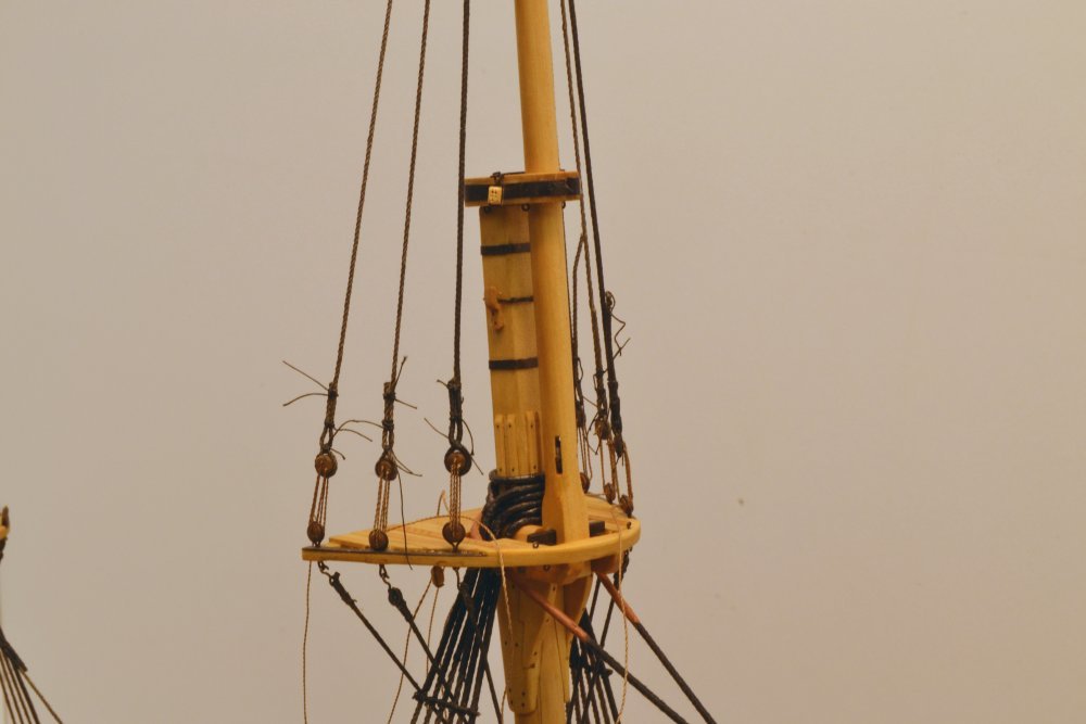
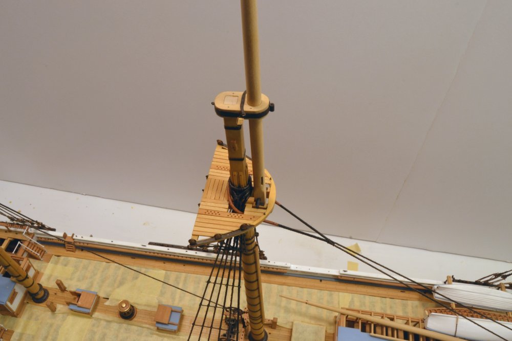
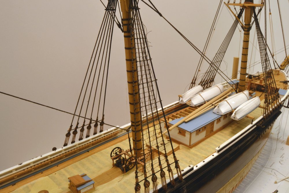
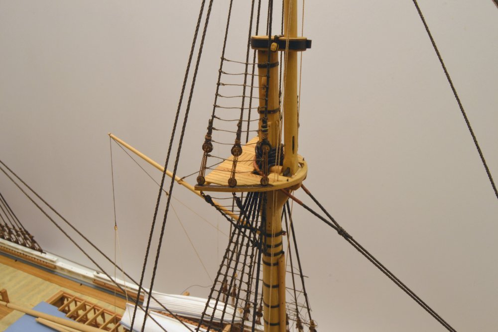
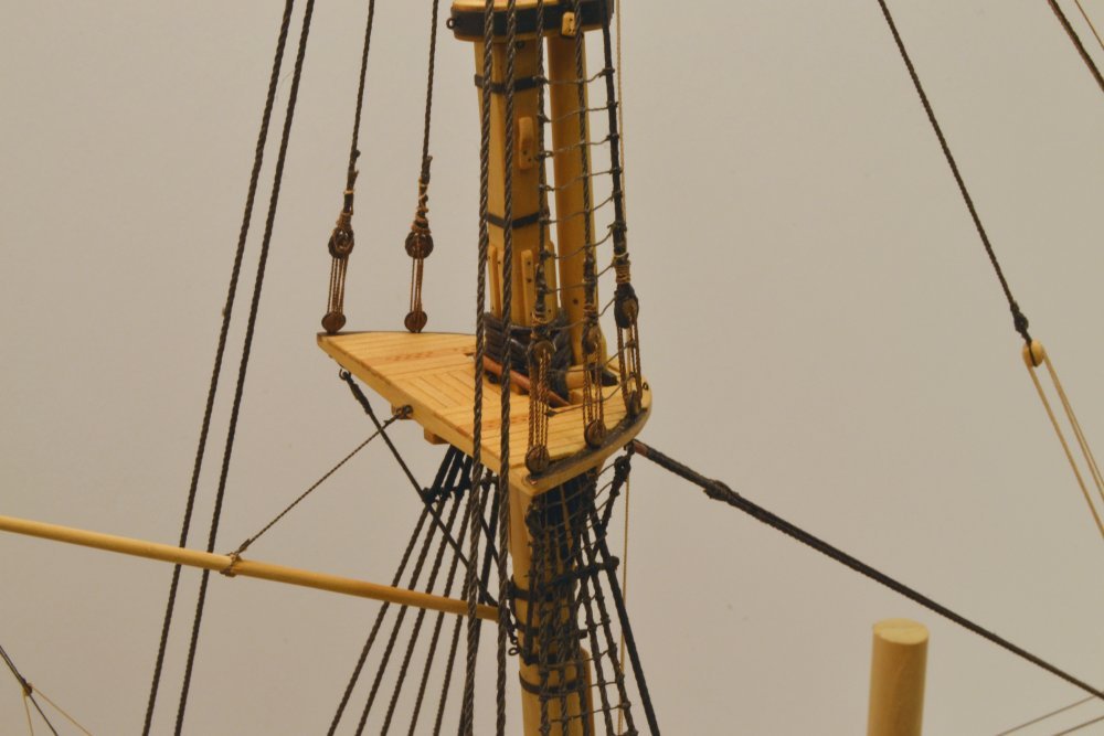
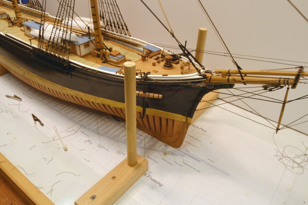
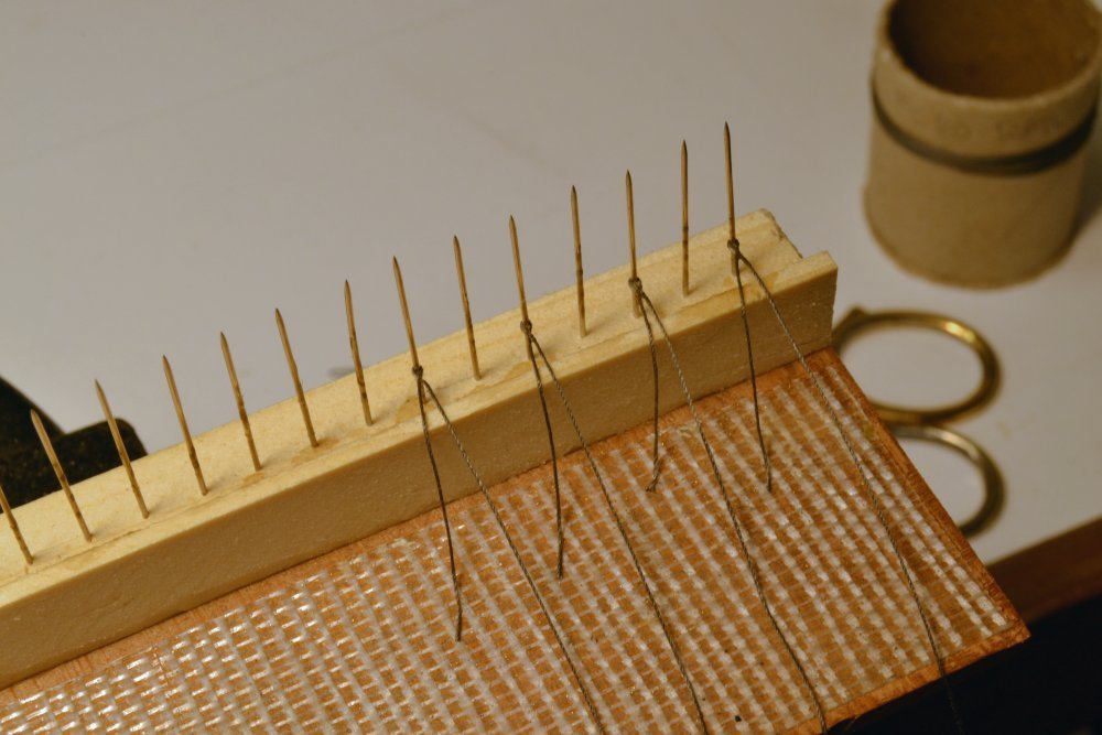
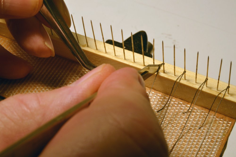
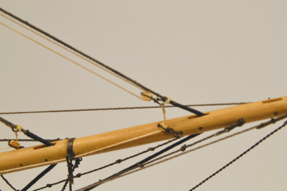
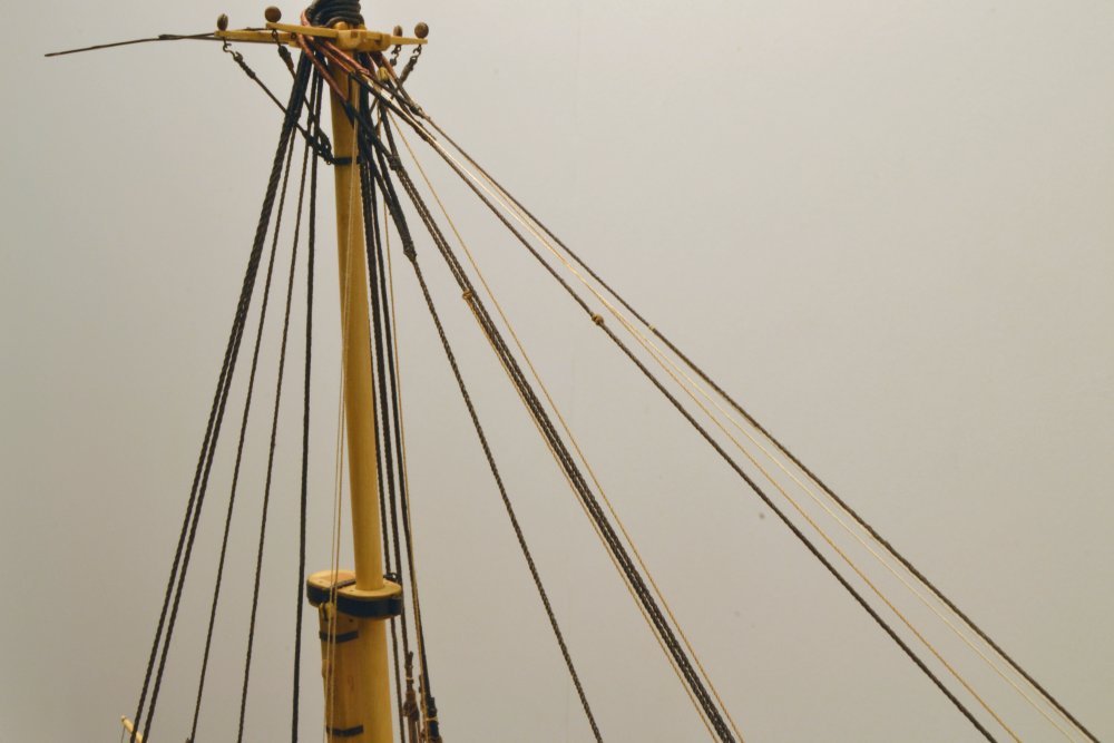
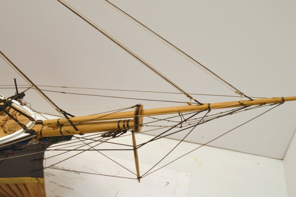
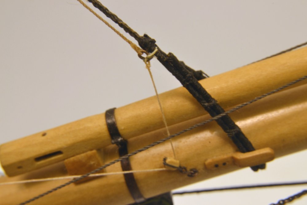
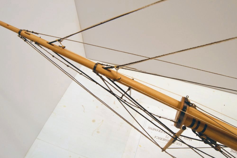
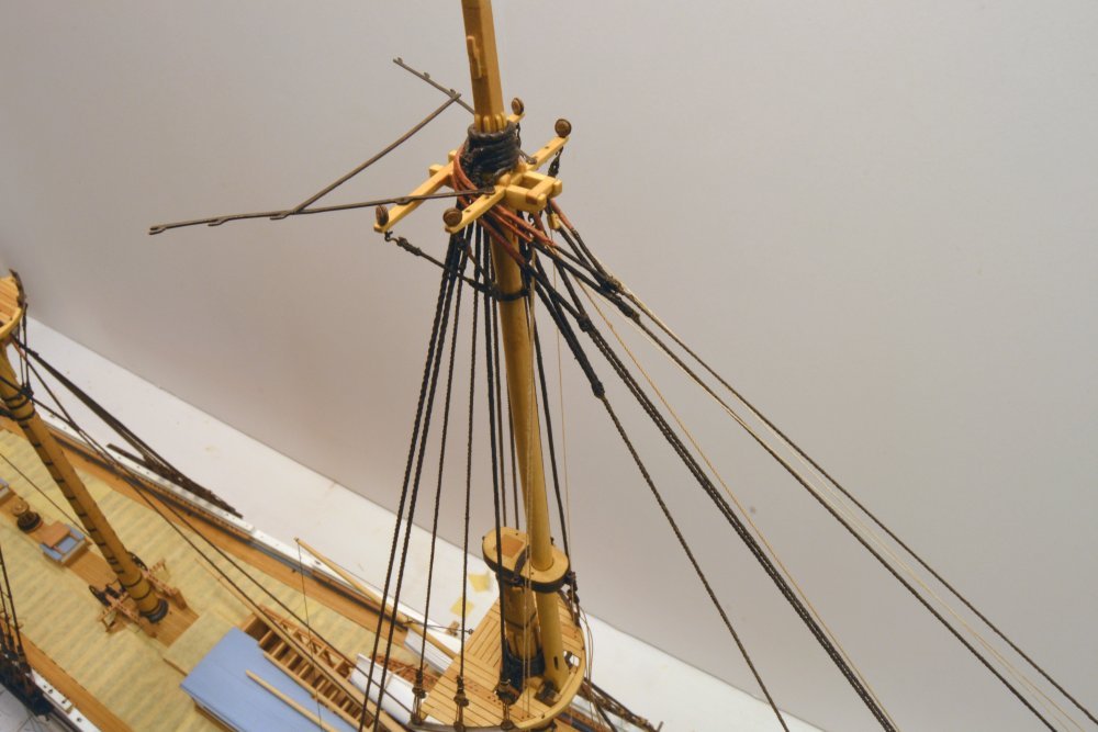
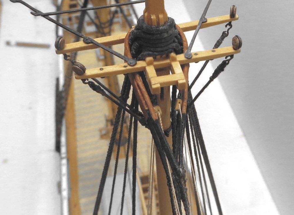
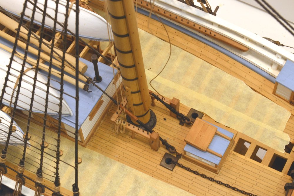
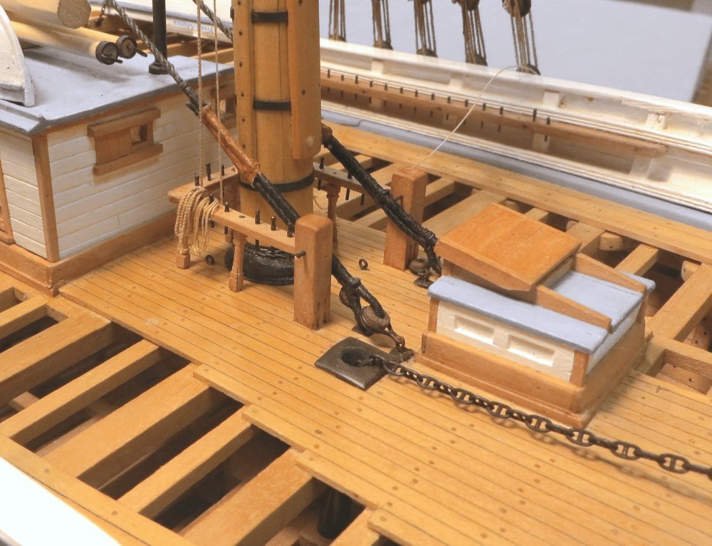
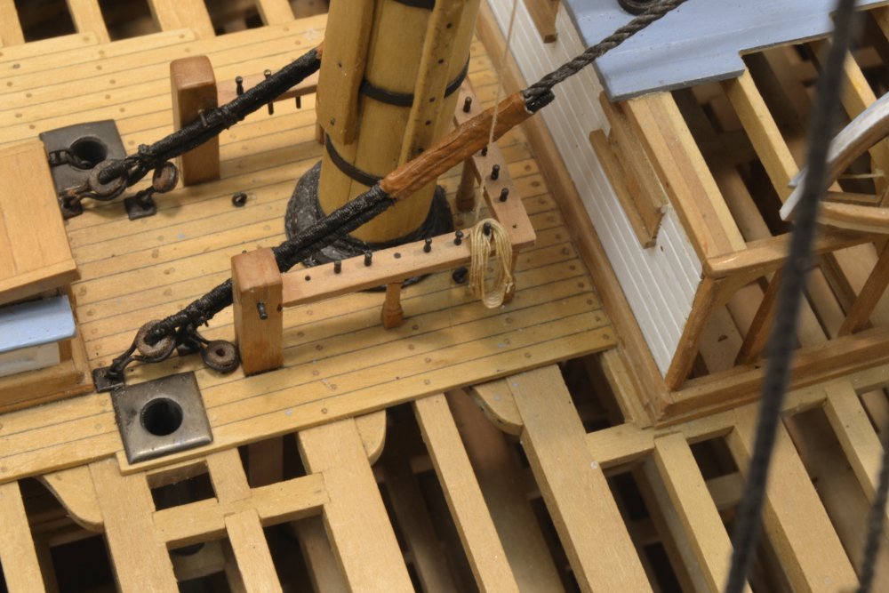
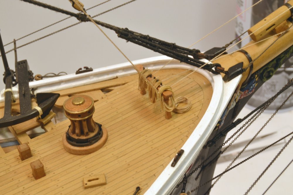
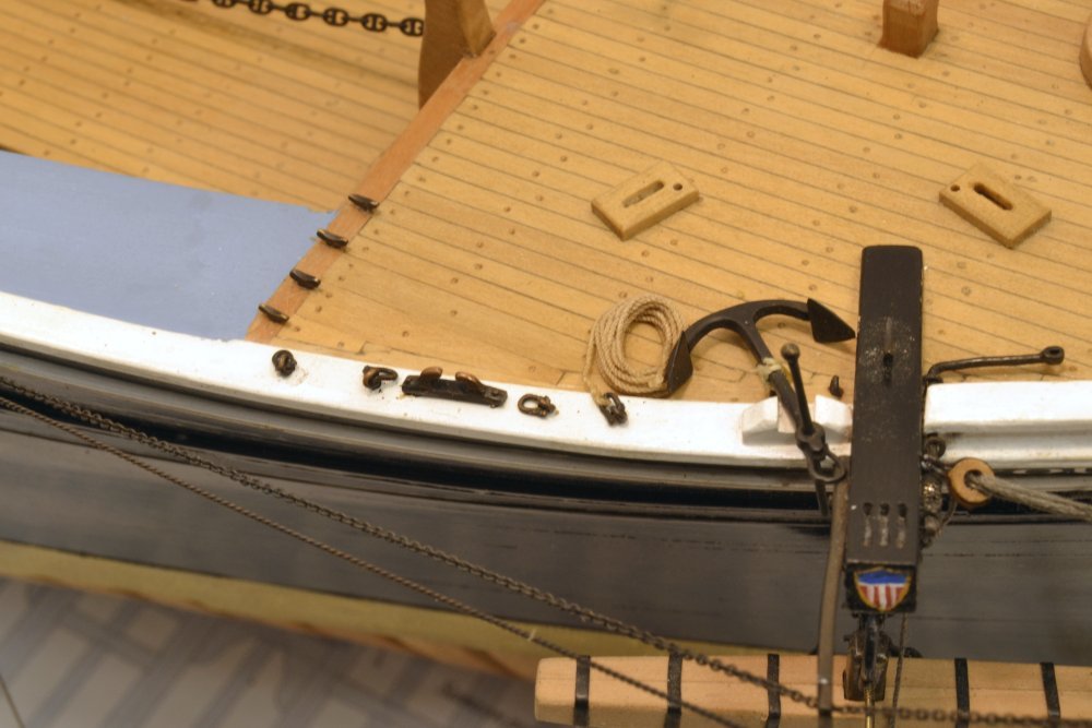
Young America - extreme clipper 1853 Part 245 – Main Topmast Stay First some backtracking. The first picture shows a sheer stave being lashed to the fore topmast shrouds. I initially omitted these but reconsidered after being prompted by a comment (Thanks, Scott) and checking through some sources. This is a 1½" diameter wood stave as opposed to the served 1" iron poles on the lower shrouds. The excess ends and the loose lashing ends will be removed later. This picture shows the starboard topmast backstays. The next picture shows the 10½" backstays on both sides placed over the masthead. Before securing these at the channels below, I decided to install the 9" main topmast stay - for two reasons. First, it will be easier to use the backstays with their lanyards for final tensioning rather than the forward stay that loops through shackled bullseyes on the deck. Second, I have been anticipating a difficult task in fixing this stay at the lower end and wanted to get on with it. In the next picture, the stay is looped over the masthead and being marked at the limits of the upper serving where the two legs will be seized. The lower ends of both legs of this stay are also served from abaft of the foremast, down through the bullseyes, and back up to the ends of the seized legs – as will be seen below. The next picture shows one of the long lower legs being served. The needle through the rope marls the end of the served length and will allow the thread to be pulled through the rope at that point to fix the end. The next picture shows the lower ends being fastened to the shackled bullseyes. Making these ends fast in the tight space was even more difficult than I expected, mainly because I did not allow sufficient diameter in the bullseye holes to easily pass the served line. I spent almost an hour getting the port leg through the bullseye, including refitting the bullseye into the shackle several times. The picture shows that side seized and the stay being pulled through the starboard bullseye. After enlarging this bullseye hole at the start, this side took about a minute. There is a moral to this story. The next picture shows the completed lower end. There are four seizings on each lower leg and simulated leathering in the area of the rubbing battens on the mast. Another concern I had about this arrangement was clearance between the four large, doubled lines and their fixings in the deck, as well as clearance around the mast. This all worked out as planned - fortunately. The next picture shows the upper end of the stay. The next picture shows the full completed stay. With this stay in place, belaying on the fore fife rails may proceed without having to thread these large lines through later, meaning that work can now begin on the yards of the foremast and their many running rigging lines. But first, completion of the main topmast backstays that are temporarily clamped in the picture. Ed
- 3,618 replies
-
- 31
-

-
- young america
- clipper
- (and 1 more)
-
ancre Chebece 1750 by Jeronimo - FINISHED
EdT replied to Jeronimo's topic in - Build logs for subjects built 1501 - 1750
Superb work as always, Karl. Ed -
Young America - extreme clipper 1853 Part 244 – Main Topmast Shrouds The first picture shows the served and parceled forward topmast shroud pairs placed over the masthead to allow the parceling glue to set. The parceling is white tissue glued with plain PVA white glue. Although this dries quite rubbery, letting it dry around the mast makes the eventual shaping and seizing easier. In the next picture all six shrouds have been "tarred" with acrylic artist's paint, seized and pressed down into position. The aft shrouds have a single eye, it was probably spliced, but I used a simpler/stronger seizing since these will be totally covered by stays and backstays. Some excess seizing thread has yet to be sliced off. The next picture shows the two backstay pairs served, parceled and placed over the masthead. The backstays will be permanently fitted after the shrouds are installed. That process is shown in the next few pictures. In the first picture the upper deadeyes have been wired to a sheet of wood as was done previously to help in seizing them at a uniform height. The first steps in making the throat seizing on the served forward shrouds is shown above. The seizing thread was tied off to the standing leg then passed through the opening above the deadeye with the curved needle as shown – from left to right. In the next picture, the thread was taken behind the standing leg and back through itself to form a single hitch as shown below. This was then pulled tight and two more hitches added to produce the throat seizing. In the next picture a frapping turn is being threaded to tighten the seizing. A little "photoshopping" was done on the seizing turns to highlight the way the turns are placed. The frapping turn was ended with a hitch. After this, the short leg was pulled up next to the shroud and clamped to allow the round seizings to be added. In the next picture the forward shroud has had the two round seizings added and has been wetted with diluted dark glue to seal the knots and the serving on the short end. The second shroud has been clamped for seizing. The last picture shows the six shrouds with their lanyards threaded Lots of loose ends to be sliced off in this picture – the last step after letting the glue completely dry. Next the backstays, then the doubled topmast stay down to the shackled eyes in the deck forward of the fore mast. Ed
- 3,618 replies
-
- 38
-
-
- young america
- clipper
- (and 1 more)
-
You are welcome, Toni. I did use the profile cutter described in Naiad II to make those deadeyes - and the method produced a satisfactory set - with the finish polishing steps. I have regretted (and apologize) that size and shipping weight issues, the number of drawings with that book, and the large amount of content, limited some descriptions could have been more complete - I think the deadeye description was a paragraph or two (compared to five pages in YA II). I would have said more about turning speed and emphasized the relief angle under the cutter. Getting the grinding of the backside of the cutter along the entire profile was not easy. That, coupled with the larger number of sizes and smaller sizes on YA led me to the single pointed or rounded cutters that required more tool changes and settings, but were able to produce a wider range of sizes - some down to 1/16". As you probably know from the book, the Naiad deadeyes were Swiss pear. Ed
-
Very nice work, Toni. I appreciate the issues with turning deadeyes. I wish I could say that my turnings are exemplary, but they are not, but here are some personal thoughts about smoothly finished turned deadeyes and other small parts: I would strongly second Danny's recommendation on using genuine Euro Boxwood for its superior hardness. It can be found online. Since it will be stained and small pieces can be used, color imperfection common in current offerings is not an issue. In comparison with other species, relative hardness properties according to an online Wood Database are proportionately as follows: Eurobox, 2840; Castello 1800, Swiss pear 1660, Hard Maple 1450, Cherry 950 and, for comparison only, Basswood 410. So apart from color, cherry is not a good choice. Pear is much better if color is paramount. Some other things to consider that I have found helpful: Smooth turnings are best produced by tools that shave vs. tools that scrape. Most contour cutters are scrapers because it is very difficult to sharpen a complex shape to take shavings. For example, furniture turnings that are shaved require very little sanding compared to those made with the usual scraping tools - unless a burr is formed on the edge - not practical on small tools. Also, a wide cutter will rip out more fibers that a narrow tool. Single pointed or rounded cutters with correct relief angles (about 20 deg for wood) have the best chance of shaving. Use the calibration wheels to form the shapes. Use the very highest turning speed and the very lightest feeds when using a machine lathe designed for metal cutting - like Unimat or Sherline - espeicially with wide contour cutters that put a lot of stress on turnings. Round and polish with fine abrasive sticks - 320-400, then 1200 grit and up. Use a non-fading stain, either pigmented (say Minwax) or natural water soluble dyes like walnut extract/VanDyke crystal solutions. I am currently using the latter for these parts and more diluted solutions for hemp rigging. Hope these ideas are helpful. Ed
-
Thank you, Dave. Yes, I leave the hooks slightly open so they are easy to slip into the deadeye straps, then give them a bit of a crimp with pliers after the shrouds are permanently fitted. These are 26 gauge (.016", .4mm) wire. I have had no problem with them opening up under tension. The lower shroud hooks are 24 gauge (.02", .5mm). Ed
- 3,618 replies
-
- 5
-
-
- young america
- clipper
- (and 1 more)
-
Young America - extreme clipper 1853 Part 243 – Main Topgallant Futtock Shrouds In Part 231, a method for making the served eye splices for futtock shrouds was described. For these shrouds, a different method – I believe a better one – was used. The first picture shows two steps in the sequence used, in this case on the hooked upper ends of the shrouds. I omitted thimbles on these smaller eyes. A length of the 5" rope was first served. In the splice on the left, the rope was threaded through the hook and clamped (not shown) to form the eye. The eye was then clinched tightly with serving thread – an overhand knot and a clove hitch – leaving a long length of thread. On the right, the short end has been clipped off and the serving unraveled back to the clinch as shown, to expose the bare rope. In the next picture the rope end has been untwisted and the strands cut on a taper. Glue was then applied to the bare and served rope over the length of the splice and the length of thread used to serve over the spliced area. I am using darkened wood glue on all these standing rigging knots and joints. CA would produce a stronger joint, but I am trying to avoid its use. The darkened Titebond has more than adequate strength with this joint design. A finished splice is shown below. By removing the serving over the short end, the joint is strengthened over the previous method where the serving was left on. Tapering the strands improves the shape of the splice. The method is also much faster because it eliminates glue-drying steps. In the next picture one of the shrouds is being lashed to its eyebolt. The lower eye, after measuring the shroud length, was formed as above but without the hook. Handling during all these steps takes a toll on the metal blackening, so this will be touched up with LOS before finish is applied to the mast. The next picture shows all four futtock shrouds installed. As usual, the loose ends will be sliced off after the glue dries. In the last picture the topmast has been set with a spot of glue on the aft face of the lower square, held in place with a wedge against the forward rim until the glue dries. A permanent spacer will replace this wedge later. Next, the topmast shrouds. Ed
- 3,618 replies
-
- 32
-
-
- young america
- clipper
- (and 1 more)
-
Hi Danny, I have noticed your catching up on the YA posts and appreciate the interest and your generous comments. Thanks for your suggestion about references on the drawings. I will consider it. As you may know, the books have been completely separate from the online posts, both in content and format. The books have been focused on modeling methods in detail and the posts more on pure progress with some process overview. I expect this to be the case in the expected next book on masting and rigging Young America - and in fact the American 1850-60's clippers in general. Although the basic planning of the next book is well along, I have just begun outlining it and deciding how to present the huge amount of detail that the topic involves - so thanks for the input. Frank, I have made some space in my mailbox. Ed
- 3,618 replies
-
- 6
-
-
- young america
- clipper
- (and 1 more)
-
Thank you Druxey and wyz, and for the likes. Sorry if some of the material is somewhat repetitive at this stage - a bit like groundhog day - good preparation for the 20+ yards and booms that lie ahead. Cheers, Ed
- 3,618 replies
-
- 3
-
-
- young america
- clipper
- (and 1 more)
-
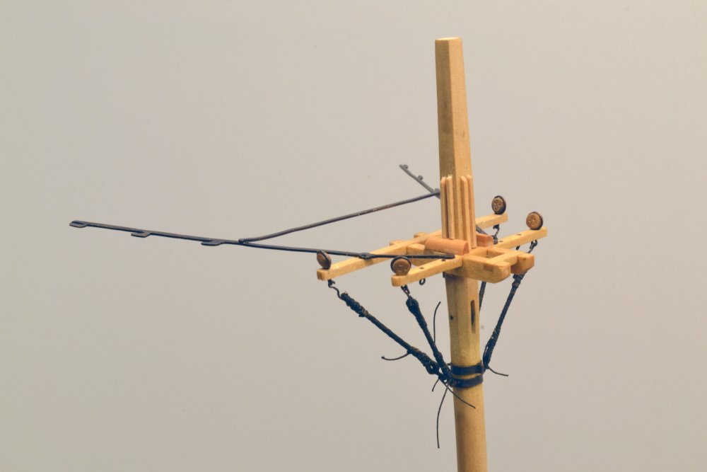
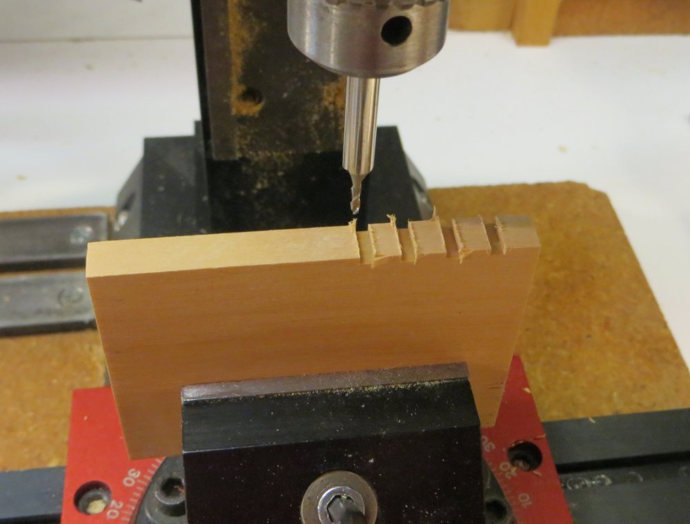
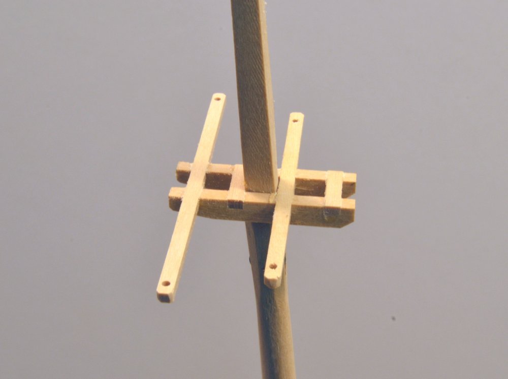
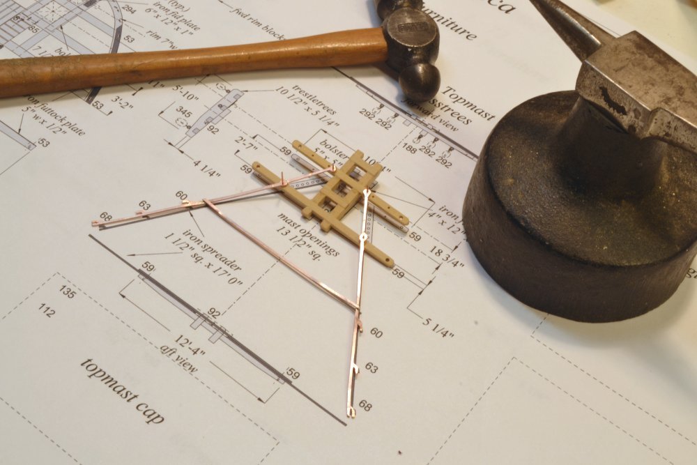
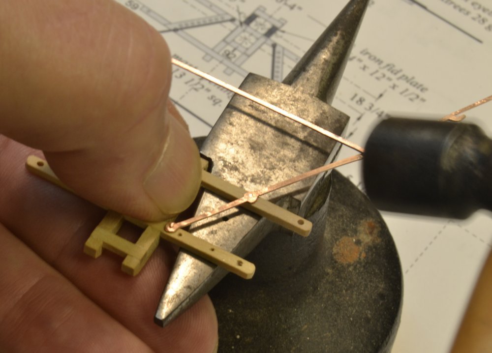
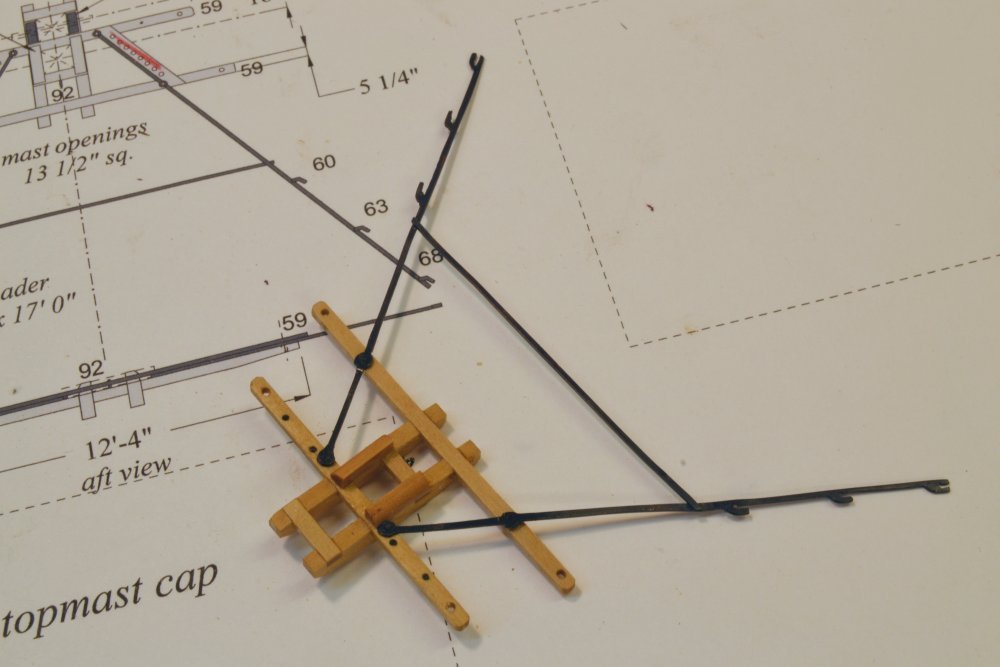
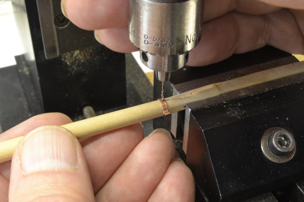
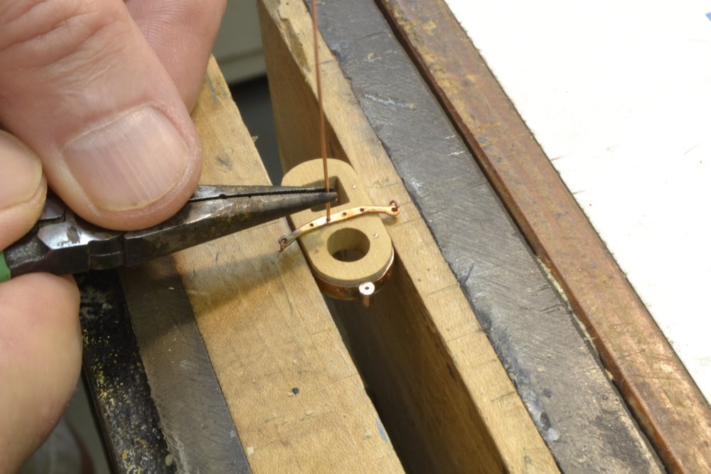
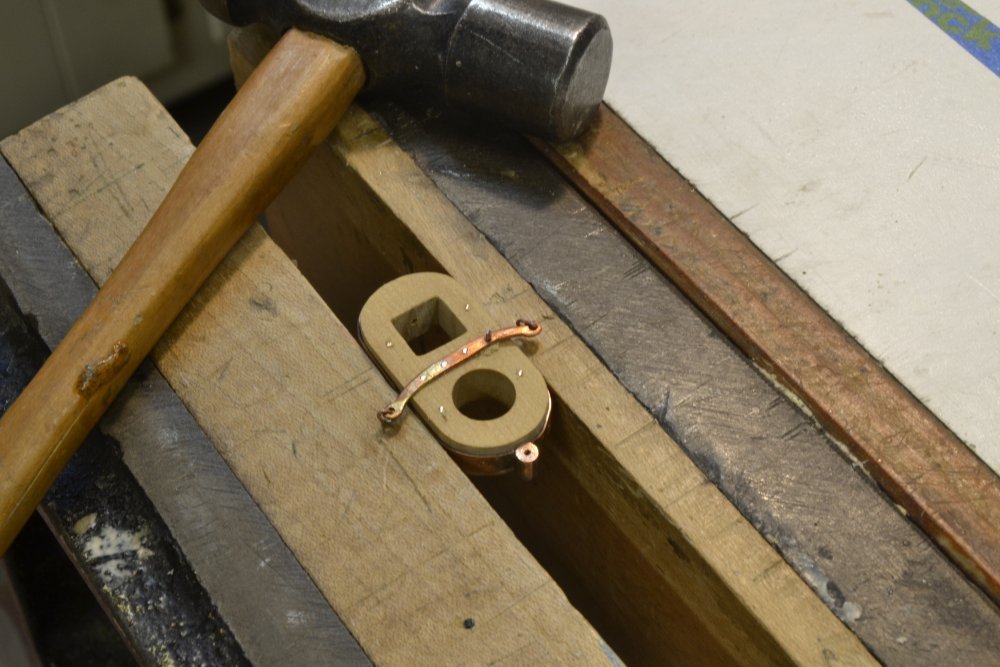
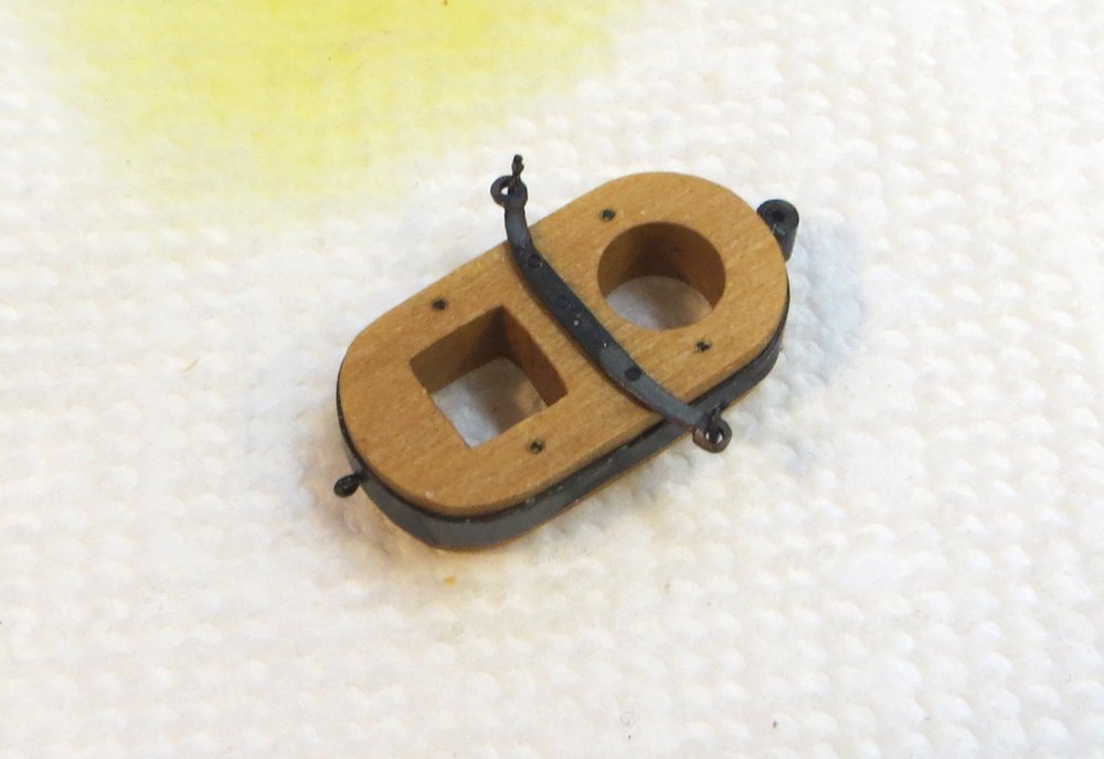
Young America - extreme clipper 1853 Part 242 – Main Mast Crosstrees I cut the trestletree mortises for the fore mast crosstrees by hand but decided to mill them for the main and mizzen masts – for accuracy and simplicity. It is an easy milling task. The mortises in the mizzen trestletrees have been milled in a block of Castello in the first picture. The top of this piece will be next ripped off at the depth of the trestrees and that piece then ripped to the width, producing two, identical trestletrees that can be cut to length and beveled on the bottom corners. The basic assembly is shown in the next picture. The arms have yet to be tapered on bottom faces. The iron backstay spreader shown below was produced in the same way as the foremast counterpart, described earlier in Part 230. In the picture the copper assembly has been soldered together, wire bolts have been inserted into pre-drilled holes in the crosstree arms, and the bolts are ready to be peened to rivet the spreader to the arms as shown in the next picture. In the picture the holes for the underside eyebolts have been drilled but the eyebolts left out at this stage to allow hammering of the bolts on the small anvil. In the next picture the eyebolts have been added and the ironwork blackened. The assembly was given a thin coat of diluted Tung oil in the above picture. The next picture shows the futtock band on the main topmast being drilled for its eyebolts. As mentioned in an earlier post, this band goes on after the lower mast cap, so it is fastened by means of the bent tab seen in the picture. Setting the eyebolts in the drilled holes keeps it in place. The last picture shows the completed assemblies. The lower mast cap is on the mast but out of this picture. The crosstrees are ready to be installed on the mast. The next step will be to install the topgallant futtock shrouds before setting the mast. Ed
- 3,618 replies
-
- 34
-
-
- young america
- clipper
- (and 1 more)
-
Pat, like hammering a glass nail. For through bolting or nailing - leave only about 1/64" above the surface. Carl, by most accounts not very well. If you mean as a profession - no. Ed
- 3,618 replies
-
- 3
-
-
- young america
- clipper
- (and 1 more)
-
SOLEIL ROYAL 1669 by michel saunier
EdT replied to michel saunier's topic in - Build logs for subjects built 1501 - 1750
Absolutely magnificent. Ed -
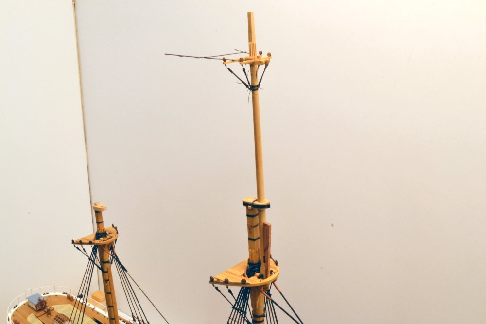
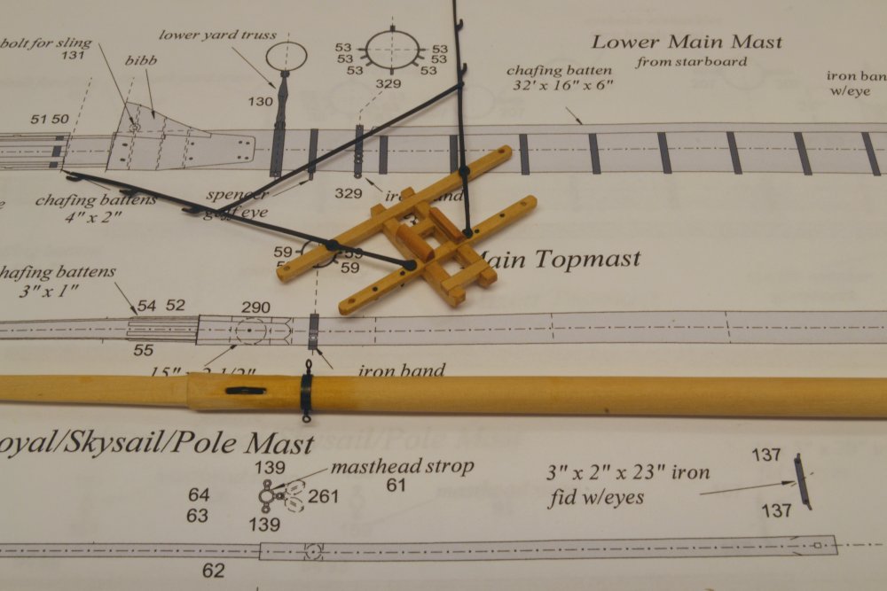
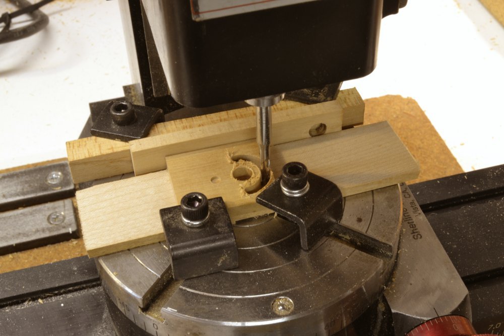
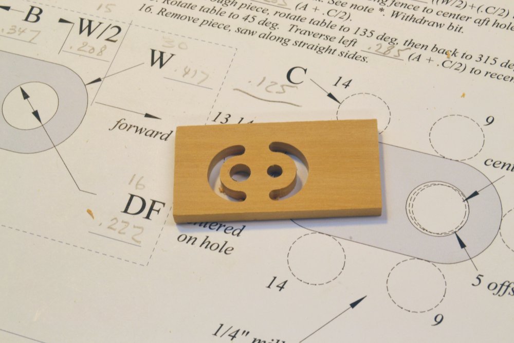
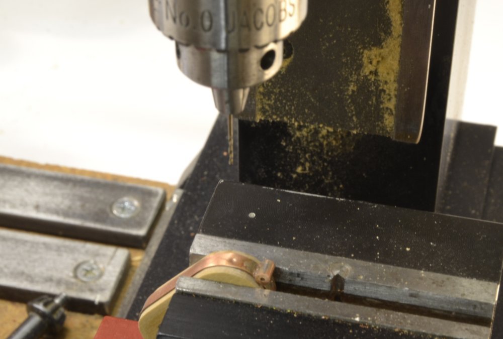
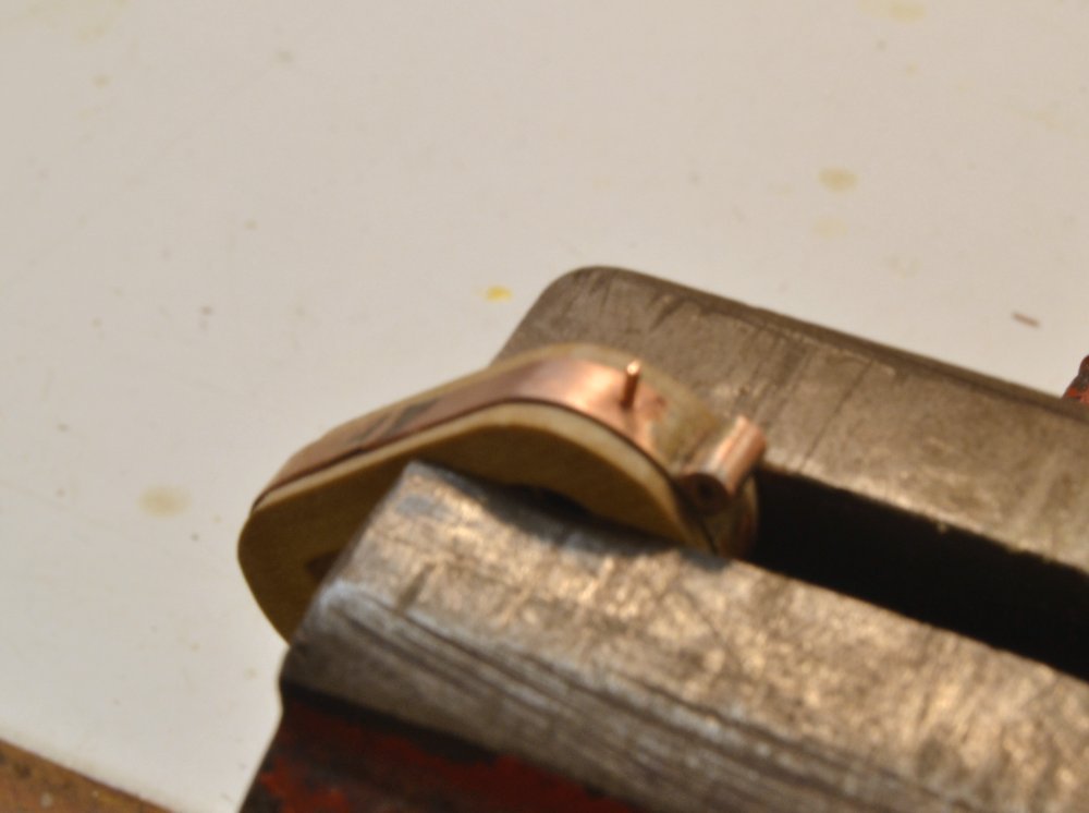
Young America - extreme clipper 1853 Part 241 – Main Mast Cap The cap on the lower main mast is identical in configuration, but very slightly larger than the fore mast cap that was described in Part 227. That cap was relatively simple to make since the 18" round and square openings scaled conveniently to a ¼" drill bit. None of the other caps offer this convenience. Because of this, the need to for precision in spacing the holes, and to accurately cut the outer radii, a method was developed to shape all the remaining caps on the milling machine with the aid of its rotary table. The first picture shows the lower mizzen cap being milled by this process. The method used requires a number of sequenced steps and various calculations that I will not attempt to describe here. The next picture shows the mizzen cap after the milling steps. The holes, spacing and exterior radii are all accurately formed and the piece is ready to be sawed out along its straight sides. The hole for the lower mast tenon (on the right) will be manually squared to match the hole diameter. The piece is pictured on a worksheet that was used to facilitate the calculations and prescribe the 16-step sequence used. After this, the steps for the main mast cap were the same as those described in Part 227. The next two pictures show steps not described earlier, in which wire "bolts" were placed on either side of the boss for the lower topsail truss to assist in taking the weight of that yard on the forward end of the band. Holes were drilled on both sides at the forward end. The eyebolt on the aft end serves a similar strengthening purpose. Copper wire was then forced into the holes, cut off just above the band surface, and then peened over. The next picture shows a similar copper wire bolt being inserted to secure the cap iron. Each of these was then nailed in and peened over as shown below. The picture also shows the ends of the four eyebolts inserted from below. In the next picture the entire assembly has been washed (and is still wet) with liver of sulfur solution used to blacken the copper. The wood is still wet, but will dry to its normal color. The yellow spot on the paper toweling shows where the solution was blotted. The last picture shows the dried and finished cap temporarily in place with the topmast inserted. The double blocks for the topping lifts were strapped to the cap iron shackles and the fid fitted before this photo was taken Ed
- 3,618 replies
-
- 24
-
-
- young america
- clipper
- (and 1 more)
-
Thanks, Micheal. I do feel a lot more comfortable working around these booms with the barriers up. I actually had to replace one a couple weeks ago. Absolute familiarity with the locations of all these lines on the various rails was critical to the operation of a ship. Crew had to be able to pick out the right line quickly, night or day. Having to trace lines down through fairleads and the tangle of other lines would be a non-starter. In the pictures you will see many pins along the side rails and fife rails. When the model is finished, virtually every one of these will have a line attached. There was a sort of logic to the placement, but no doubt there had to be a lot of memorization. I guess on a reduced scale, its like me knowing instinctively where to find a certain drill bit or chisel in the many, seemingly dis-organized cubby spaces in my shop. Its still kind of mind-boggling. Ed
- 3,618 replies
-
- 6
-
-
- young america
- clipper
- (and 1 more)
-
Scott, this issue of the stave on the topmast shrouds is worth considering for the reasons you cite and to help keep the shrouds apart. this last point is a problem when trying to make ratlines taut. I may well add these. Thanks for the suggestion. Ed
- 3,618 replies
-
- 3
-
-
- young america
- clipper
- (and 1 more)
-
Young America - extreme clipper 1853 Part 240 – Ratlines 3 Apart from some work on the main topmast crosstrees (described later), most of the recent effort has been to make progress on the long task of tying ratlines – the seemingly endless "rattling down". The first picture shows work proceeding on the lower main mast ratlines on the starboard side. There are still a lot of loose ends waiting to be lashed down or clipped off. Work can also be seen in progress on the port lower fore mast. The next picture shows the current state of the work on the fore mast. The futtock shroud ratlines have been added as well as the first several on the fore topmast shrouds. A closer view of those is shown below. The lower two are fitted to the deadeye lanyards, something I had not seen before but which can be seen in one of the photos of the ship – barely. Another view of this is shown below. I finally – after some mishaps – installed some people barriers just outside the whisker booms as shown below. These might not withstand a determined punch – but the 5/8" dowels are more than enough to deflect or stop the casual nudge when I am focused on some nearby task. In a previuos post I showed a jig for putting eye splices on one end of a ratline, A production version of the jig is shown in the next picture. This one has plenty of pins to support "mass" production. Also, the two-faced carpet tape is applied to the jig itself allowing me to remove the fixture from the vise without cleaning it off the vise jaw. There is also a fence just forward of the pins so glue may be applied to each splice without welding it to the fixture. In the last picture, one of the short legs is being sliced off the splice while held taut with tweezers. Up to about 20 ratlines can have eyes spliced at a time – and very quickly. Ed
- 3,618 replies
-
- 32
-
-
- young america
- clipper
- (and 1 more)
-
Welcome back, Mark. I look forward to the renewal of your postings. Nice, well organized shop. This level of order and neatness would probably blow all my fuses. All the best in your retirement and the resumption of Bellona. Ed
-
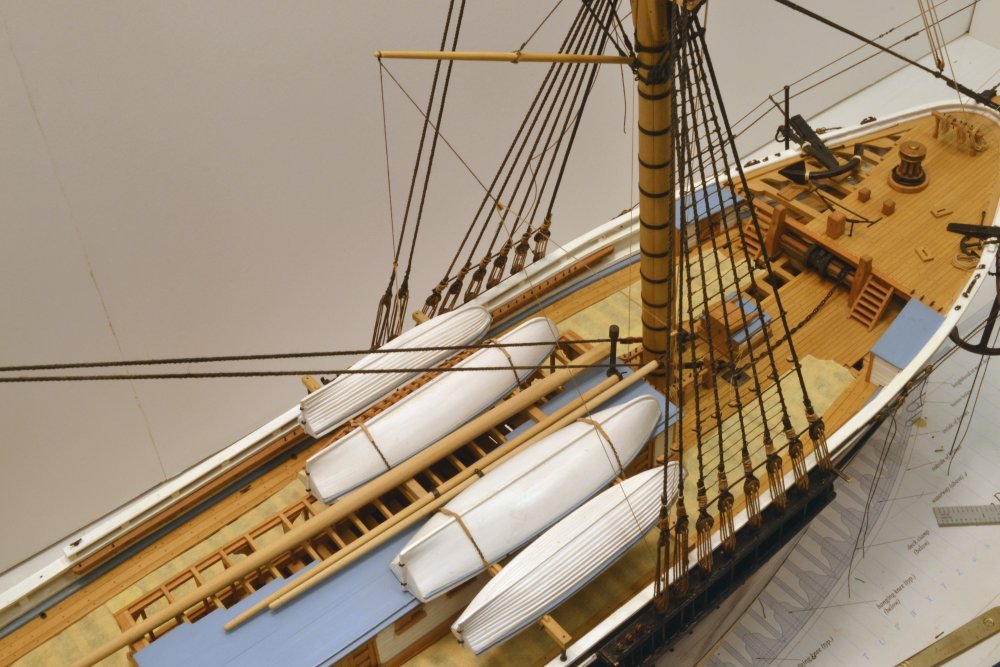
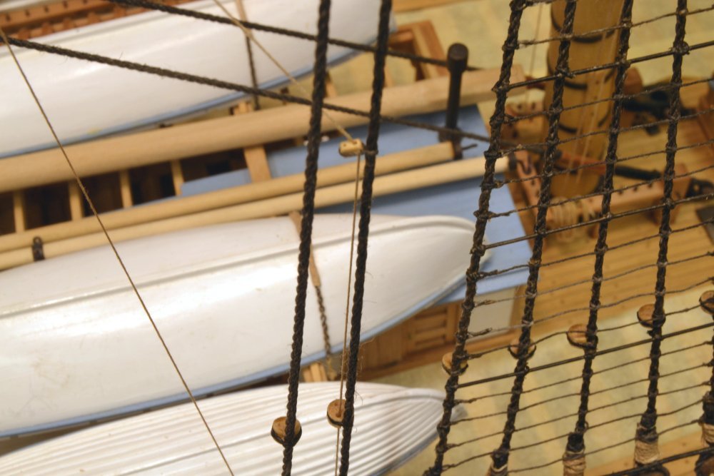
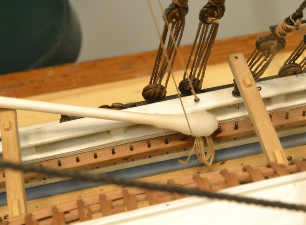
Young America - extreme clipper 1853 Part 239 – Revisions - Spencer and Headsail Rigging The running rigging described in the last two parts has been revised. In the case of the spencer gaff the fall of the vang was obstructed by the outer boats on the skid beams. To correct this, I added lead blocks to the forward topmast backstay and led the fall down to its pin through a fairlead on that stay. The first picture shows the original configuration on the port side and the revision on the starboard side. The revised rig retains the same eyebolt for the standing leg of the vang, which then passes through the block on the shortened pendant, then through the lead block and a fairlead, both on the forward topmast stay. The fall then belays on the same pin as before. The next picture shows the starboard lead block and fairlead. The old rope coils and belaying were removed as shown in the next picture. A cotton swab soaked in isopropanol was laid on the rope for a few minutes to soften the wood glue. The rope was then easily removed. The other revision involved the halyards on the three headsails. I initially considered three typical configurations for these – no blocks, a single block whip from the deck, and a single block at the head of the sail. I installed the first, simplest method as described in Part 238. Shortly after installing these, I thought more about this and was concerned about no mechanical advantage on these rather large sails. In checking (belatedly) the 1870's photo of the ship in New York, the blocks at the lower ends of the stays are clearly visible. So, that configuration has now been installed on all three stays. The foot of the topmast stay is shown in the next picture after revision. This may be compared with the first photo in Part 238. The revised lower rigging of the outer jib halyard is shown in the next picture. To avoid re-rigging the downhaulers, the lower blocks were strapped to the shackle in place – a most difficult task, especially with shaky hands. The shackle eye was tied first, then the splice at the base of the block. The inner jib stay at the left of the picture has not yet been converted. The upper ends of the stays are shown in the next picture with the standing ends of the halyards tied to the stays. The last picture shows all three halyards converted. So, we are now back on track after a short detour. Ed
- 3,618 replies
-
- 39
-
-
- young america
- clipper
- (and 1 more)
-
Extraordinary metalwork, Johann. Bravo. Ed
-
Thank you, Carl. I will confess that I am no expert and that this is a learning experience for me that I am happy to share - including the fits and starts that are part of the process. I am very glad that you find it useful. Thanks. Ed
- 3,618 replies
-
- 4
-
-
- young america
- clipper
- (and 1 more)
-
Thank you, Scott. I believe either method for the downhauler blocks could be used. I based mine on Underhill. I believe offsetting the downhaulers to the sides avoids potential tangling if they all (four on this ship) run along the centerline. Fairlead planks on the topmast stay could alleviate this. Your comment on the halyard blocks is timely. My sources on this are varied ranging from no blocks (shorter lines, no mechanical advantage) to either a block at the sail head or a simple whip below the xtrees ( longer rope, 2:1 mech advantage). I omitted blocks, but have been considering reworking the halyards to include blocks at the sail. The New York photo of the ship shows these pretty clearly, but I missed it in the original design. My rigging rework percentage is growing. Thanks for these comments. Ed
- 3,618 replies
-
- 7
-
-
- young america
- clipper
- (and 1 more)
-
Thanks, Wefalck. That is certainly an option. I am sure practices varied for storage/belaying of lines when sails were removed. So we must make assumptions and consider options. As a basic premise for this model, I am configuring the ship as it might appear in a docked situation that typically lasted several weeks - if not months - as the ship was unloaded and reloaded for the next voyage. In this case sails would most likely have been removed from the ship for onshore warehousing, inspection, repair, and/or replacement. The configuration would differ in cases where sails were merely furled or removed at sea when not needed, but kept aboard for quick deployment. The possible rigging permutations, even for this limited case, are many. I considered several options for the head sail sheets, including the one you suggested in the last post. All involve a lot of clutter on the forecastle, since the sixteen lines (2 x 4 pair) all belay at deck level where working space for several tasks is at premium. The one modeled assumes the sheet pendants are stored in lockers on the ship or with the sails. It assumes that when needed, the sails would be bent to their running rigging on the forecastle, including shackling the sheet pendants and reeving the sheets. The halyard/downhauler shackle would be brought back to the forecastle to convey the sail out on the boom using these lines. The tack would then be secured to the lower stay and the hanks or lacing to the stay applied before/during hauling up the sail. This is, of course, one assumption based on an assumption. Ed
- 3,618 replies
-
- 6
-
-
- young america
- clipper
- (and 1 more)
-
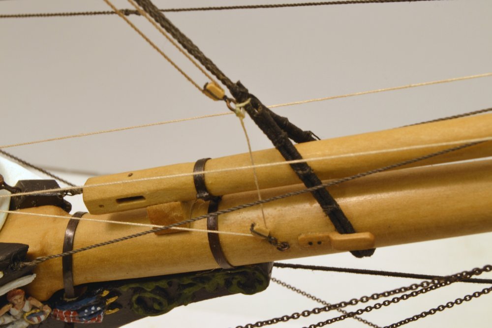
Young America - extreme clipper 1853 Part 238 – Head Sails Running Rigging Each of the three stays described in Part 235 carries a triangular headsail. Each of these sails is rigged with three lines of running rigging – a halyard to raise the head of the sail along the stay, a downhaul to bring the head down, and a double sheet to restrain the clew of the sail on the windward side. When bent to the stay, the tack at the lower end of the sail is tied off low on the stay. Then as the luff of the sail along the stay is secured with rope "hanks" the halyard is hauled up to raise the sail along the stay. Both the halyard and the downhaul are shackled to the sails head cringle. On the "unsailed" model, the halyard and downhaul eye splices are secured to the shackle, which is "stopped" to the lower end of the stay with a short length of rope as shown in the first picture at the base of the topmast stay. In the picture the smaller downhaul is led down and through a single block back to its belaying point on the forecastle. The next picture shows the lower ends of the inner and outer jib stays rigged in this manner. The downhauls and halyards for the topmast staysail and outer jib lead back on the starboard side and those for the inner jib are rigged on the port side. The next picture shows the three halyards where they pass through blocks hooked under the topmast trestletrees. The lines lead down through fairleads in the top to the fife rails below. The next picture shows the block arrangement at the topmast head, a double block on the starboard side for the staysail and outer jib halyards and a single block on the port side for the inner jib halyard. The next picture shows the staysail and outer jib halyards belayed on the fore mast fife rail. As will be seen in the next picture, the rope coils on the rails are quite small because the halyards are fully overhauled along the stay when there are no sails. The next picture shows the belayed inner jib halyard on the port side. Conversely, most of the downhauls must be coiled at the belaying points so sufficient line will be available to run up to the head of the sails when they are hauled up to the tops of the stays, so the three large coils in the next picture contain sufficient line for that. Finally, the sheets – a pair for each sail. These are shackled to eyebolts on either side of the forecastle, run through bullet blocks at the ends of a double pendant shackled to the clue of each sail, and belay on cleats on the forecastle breast beam. One side or the other is used, with the lee side slack. On the unsailed model, I have omitted the pendants and intend to coil each sheet adjacent to its eyebolt as shown in the next picture. The picture shows the starboard sheet for the topmast staysail secured to its eyebolt. When passed through the pendant block on this side, this line would be belayed on the innermost cleat on the breast beam. Eyebolts for the other head sails are arranged to the left on the rail, astride the mooring cleat. Ed
- 3,618 replies
-
- 41
-
-
- young america
- clipper
- (and 1 more)
-
JCFrankie, can't comment on the origin of spencer. Tim, the belaying pins are homemade - as is everything except the larger chain and some nails. They are brass lathe turnings using a special filing jig. There are about 300 on the model. They were described briefly in an earlier post (Part 131), but are fully described, including making the filing jig, in Young America, Volume II. You are right; the downhaul coils are quite a lot of rope. For each line, I am measuring the amount of rope for each coil based on where the other end of each line is fixed. The coils are formed "offsite" on a dummy pin rail after wrapping the rope on a plastic rod and wetting it with diluted wood glue. I will describe in a later post and in Volume III. The formed coil is then glued over the pin after the line is belayed. Ed
- 3,618 replies
-
- 3
-
-
- young america
- clipper
- (and 1 more)