


EdT
-
Posts
2,214 -
Joined
-
Last visited
Content Type
Profiles
Forums
Gallery
Events
Everything posted by EdT
-
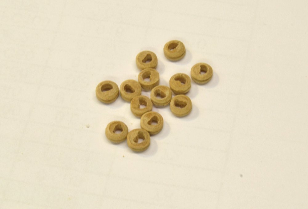
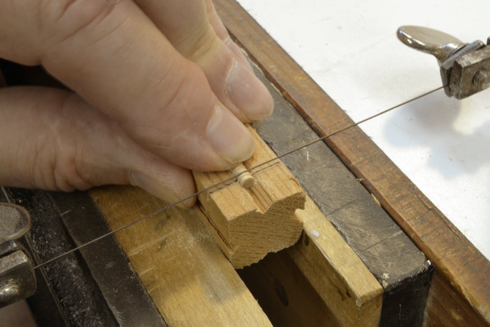
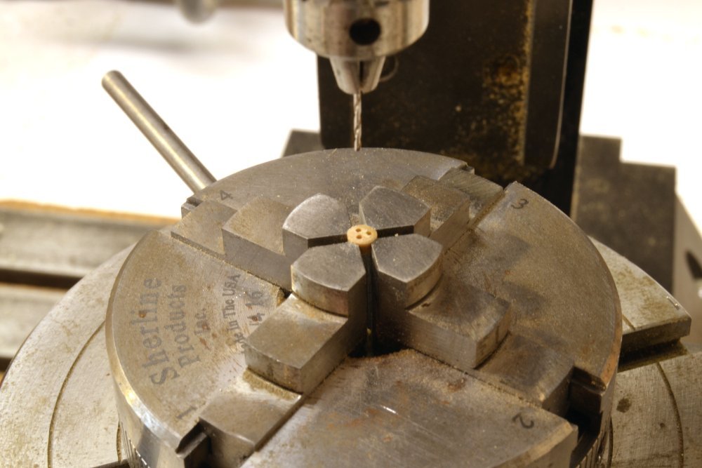
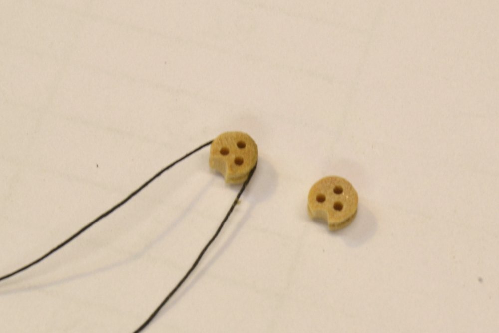
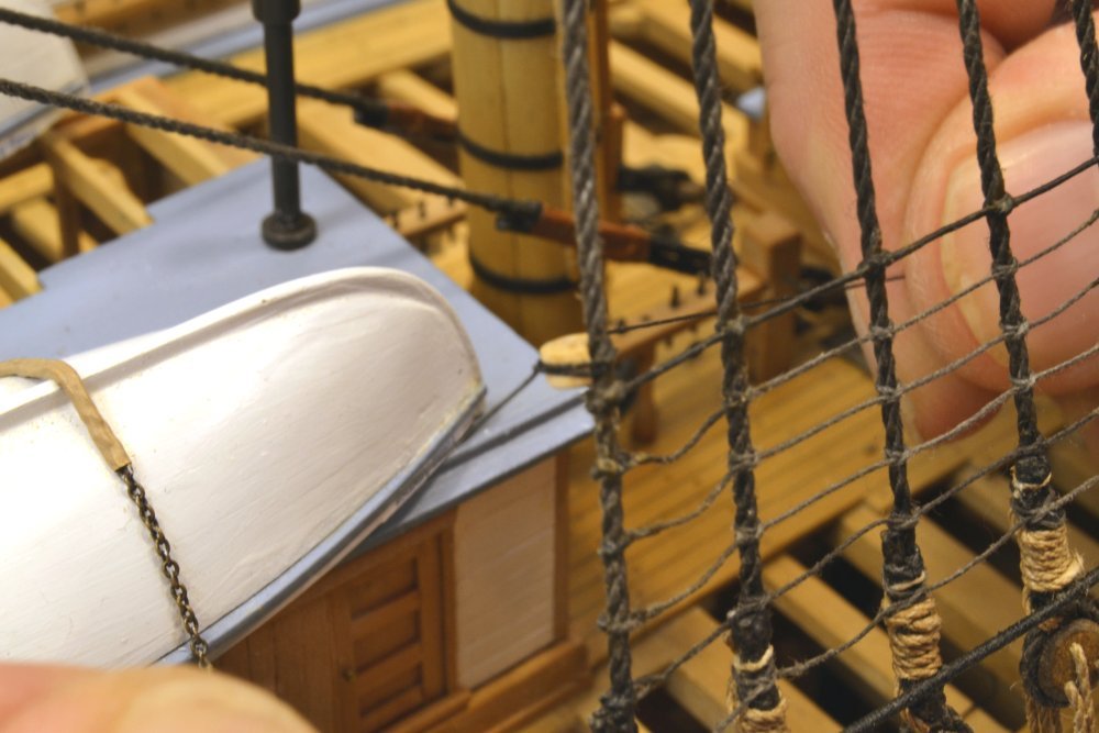
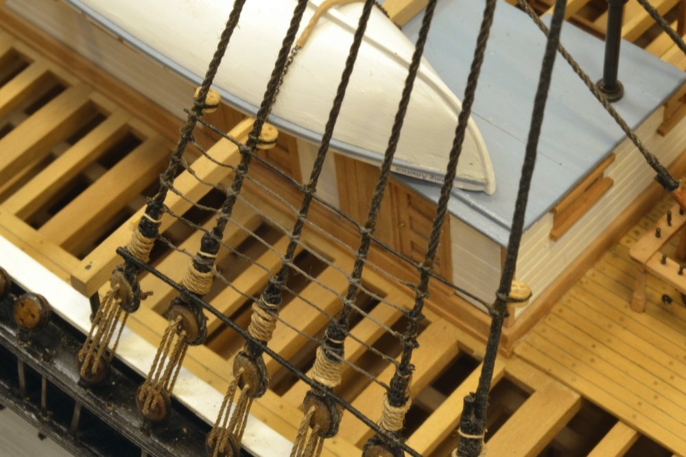
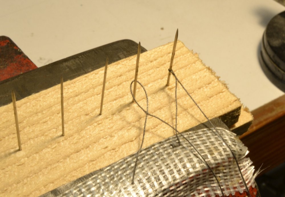
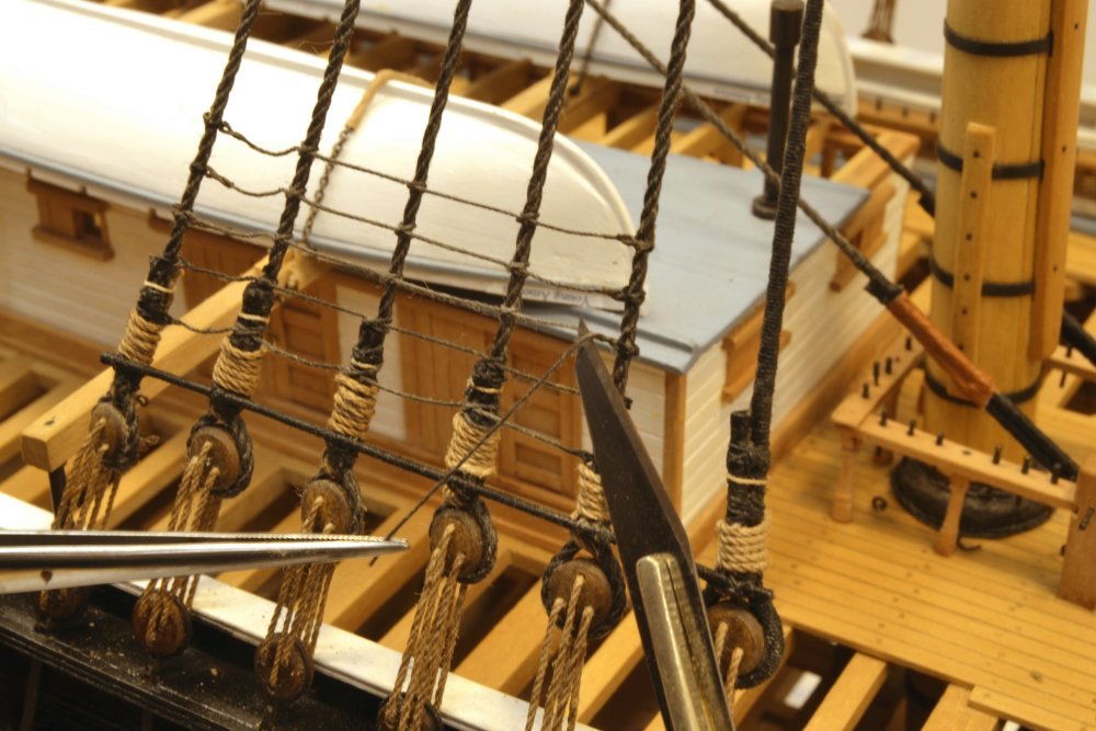
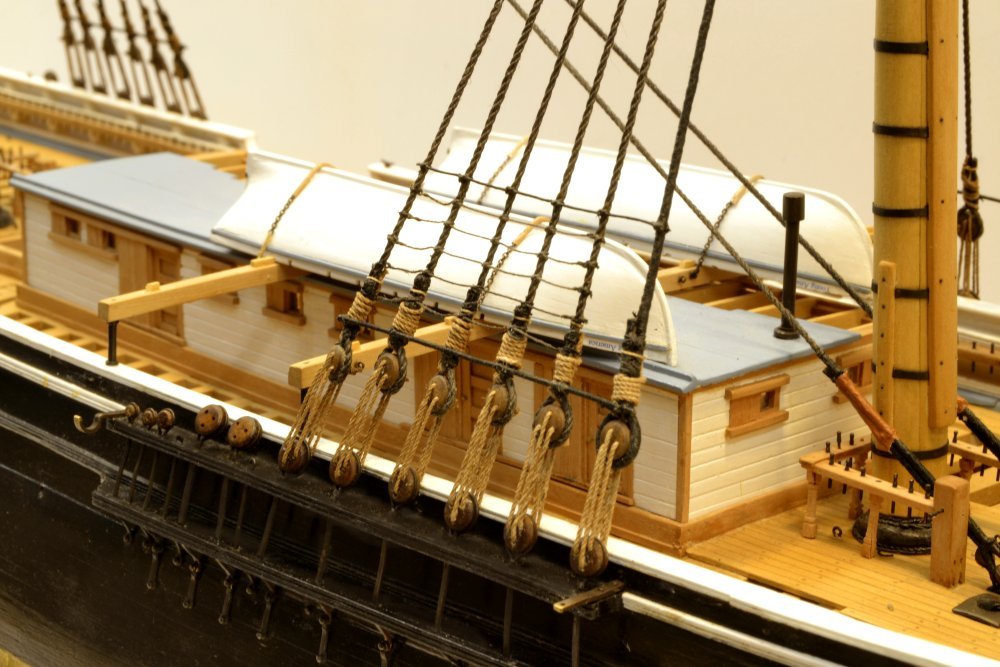
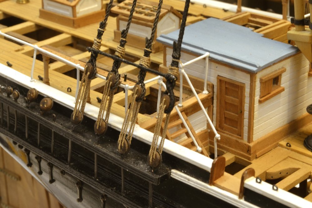
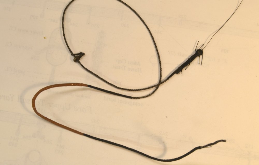
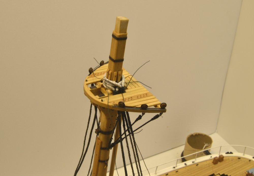
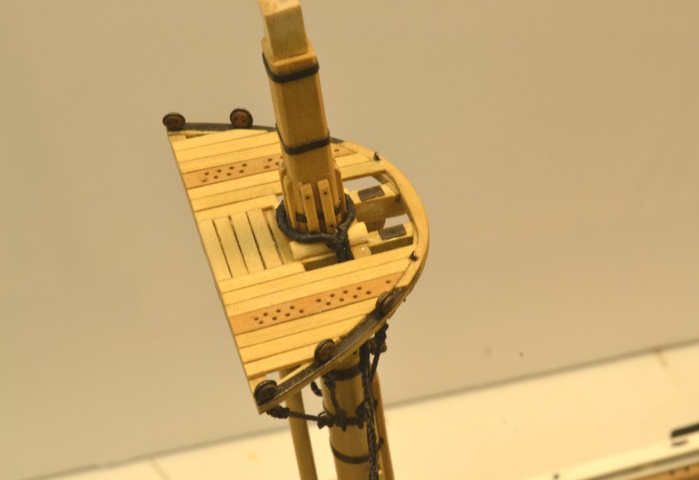
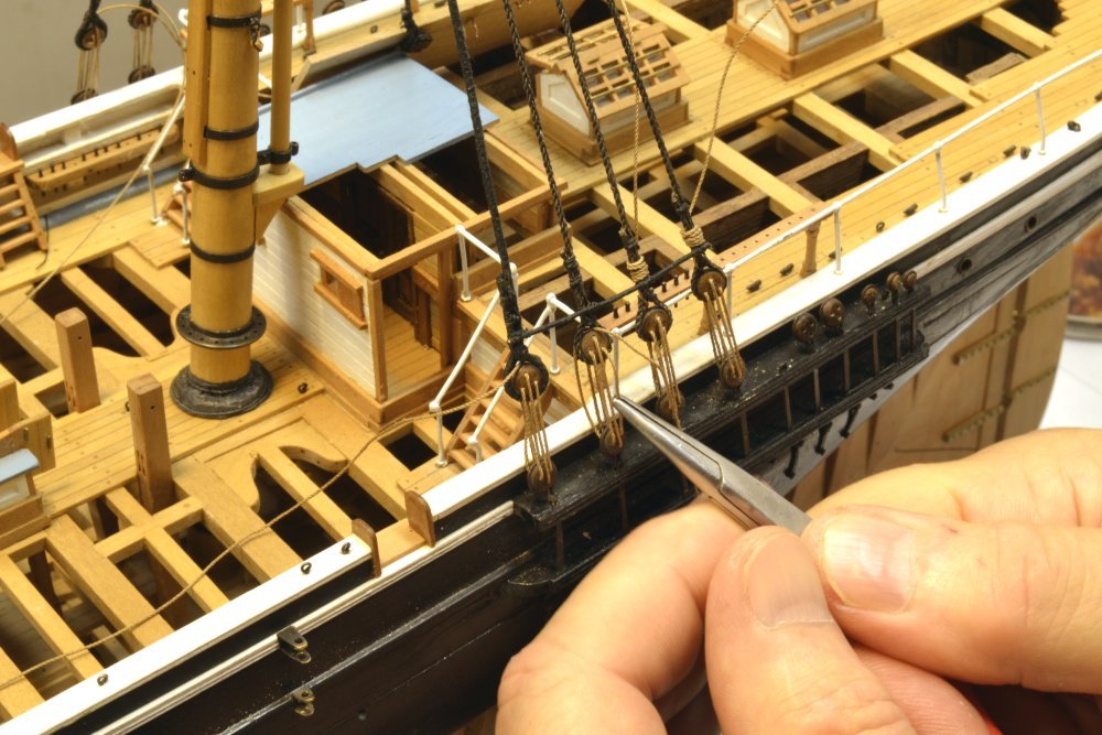
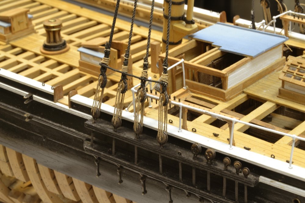
Young America - extreme clipper 1853 Part 214 – Hearts and Fairleads 1 Happy July 4th everyone – in America its Independence Day – my British friends used to say Thanksgiving Day. The first picture shows some work on the bowsprit that was made earlier. I didn't get far with the bands before realizing that the shackled hearts would have to be soldered and attached to the bands before fitting then to the spar. So the shackled hearts had to be made first, beginning with the 12" hearts shown in the next picture. Actually this sequence fit well with the next step on the shrouds, since the shroud fairleads are made with the same setups as the hearts. Heart-shaped hearts had given way to round ones by the 1850's, at least in America. These were turned like deadeyes on the lathe then cut off by hand as shown below. (This is actually a 10" fairlead being cut.) The D-shaped openings in the hearts were cut with a small milling cutter using the mill's rotary table – first boring down through the disk at the correct offset, then rotating the table 180 degrees. The small cusp left in the center was then cut out with a small chisel. The next picture shows one of the 10" fairleads being drilled with ~2" (.026") holes, using the rotary table and the method used earlier on the deadeyes. After drilling, each of the hearts requires a semi-circular notch to be cut so it will fit around the shroud. The next picture shows a notch being filed out. The next picture shows two of the 40+ fairleads (I made 50) getting ready to be lashed to their shrouds. A lashing thread has been glued to the backside of the one on the left. This pre-step makes lashing the piece to the inside of the shroud much easier. In fact a touch of glue on the outer overhand knot makes tying the second one on the inside much more manageable as well. This last part of the lashing is being tied in the next picture. The last picture shows three of the six fairleads fitted to the fore starboard gang of shrouds. The excess lashing thread has been sliced off after the glue has dried. More on the hearts in the next post. Ed
- 3,618 replies
-
- 29
-

-
- young america
- clipper
- (and 1 more)
-
Thank you, Mowse. I have read Cutler's Greyhounds of the Sea - a standard reference for clipper ships that includes the sailing records that you describe. There was tremendous attention paid to these sailing times and records. They were the subject of wagers, newspaper headlines, and did much to promote the fast passages that these ships were capable of. Young America was fast and reliable. Her performance is often eclipsed by the some of the very fastest record runs by other ships - but her near record performance for over thirty years and her 50 passages of the horn are a remarkable record. Ed
- 3,618 replies
-
- 3
-
-
- young america
- clipper
- (and 1 more)
-
Thank you, Bob - and all others who have purchased the book. Still waiting for my copies. Customers first. Ed
- 3,618 replies
-
- 4
-
-
- young america
- clipper
- (and 1 more)
-
Well. thank you Druxey - for making my day. When faced with a puzzle like finding the correct length of a ratline with intermediate knots and eyes at both ends, the answer is: don't try. I made the first splice at the workbench as shown, then lashed it to the shroud, tied the clove hitches on the internal shrouds, lashed the loose end at the opposite outer shroud without an eye, then stitched and formed the second eye in place. The third picture shows the last step in forming that in situ eye. The process was much easier than I thought it would be. However, getting uniform shape between shrouds takes some practice and I am not there yet. I don't like that fuzz on the cotton thread. Any suggestions? Longridge passed his rope quickly thru an alcohol flame and I did that for many lines on my Victory - but there was occasional attrition on the small sizes. Ed
- 3,618 replies
-
- 9
-
-
- young america
- clipper
- (and 1 more)
-
Nils, I like the photos on case construction. They are very helpful. I find case design to be something of a challenge with conflicting priorities - size vs strength, strength vs visibility, ease of disassembly, etc. Some interesting ideas here. Thanks. Ed
- 2,625 replies
-
- 7
-
-
- kaiser wilhelm der grosse
- passenger steamer
- (and 1 more)
-
Scott, I believe you are correct that either iron or wood may have been used. I assumed 1" diameter served iron for the sheer poles and staves of about one inch that could be either. My use of stiffened rope is not definitive either way and could be interpreted as either. Appearance would be similar, I assume. 1" or slightly larger diameter wood is not too practical at this scale. I would tend to favor wood as the more common material in the early years, but do not have a reference. Ed
- 3,618 replies
-
- 3
-
-
- young america
- clipper
- (and 1 more)
-
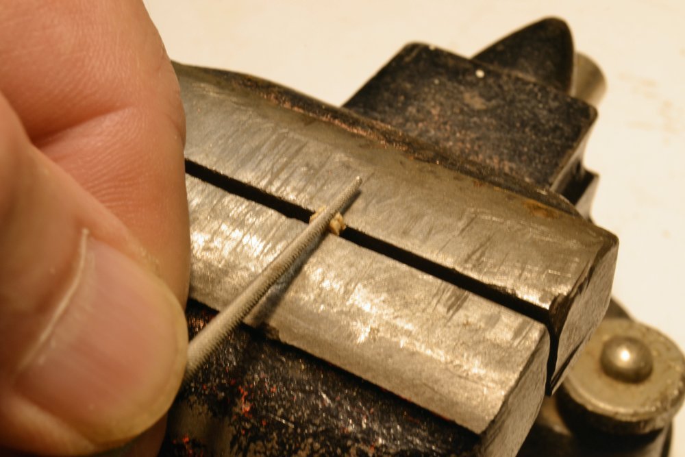
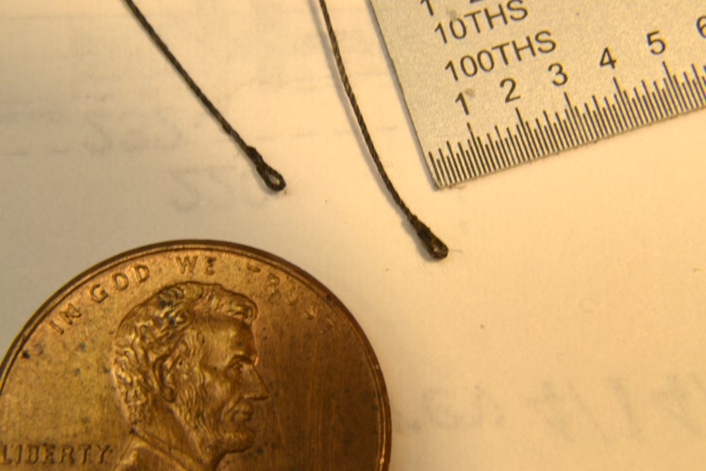
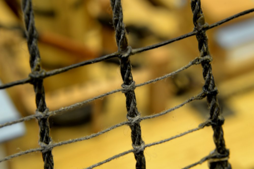
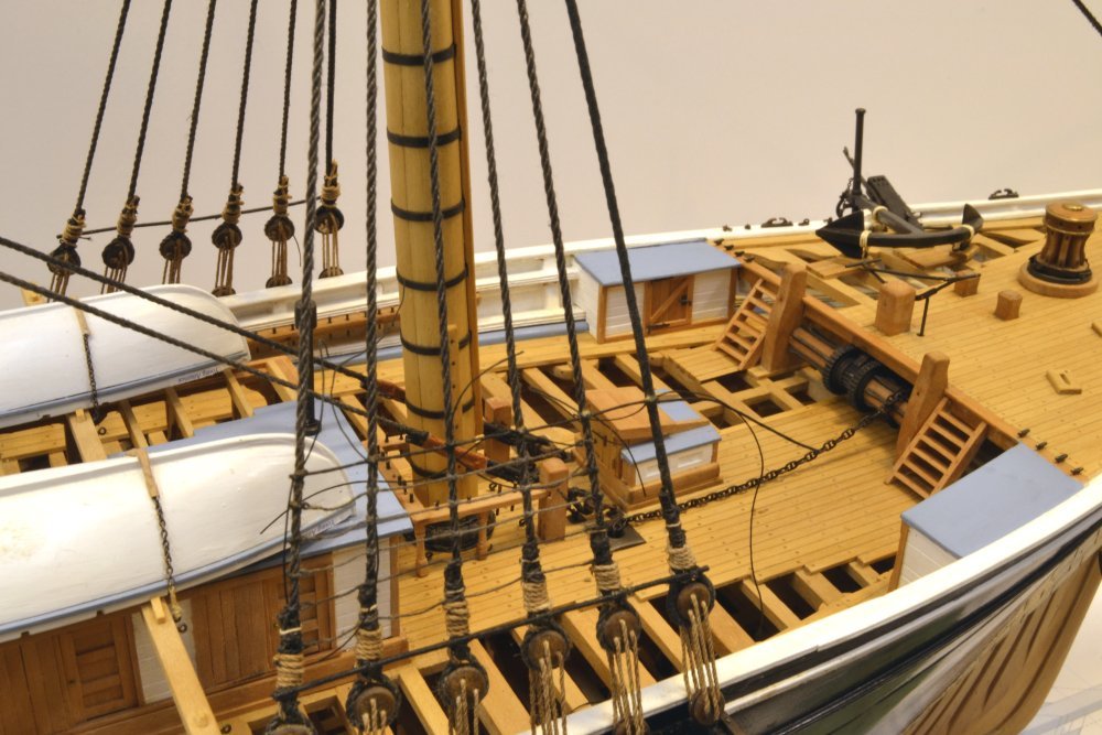
Young America - extreme clipper 1853 Part 213 – Ratlines I decided to do at least the lower ratlines next, mainly so the height of the shroud fairleads can be set and those installed early on. If I need relief from this repetitive work I can (and probably will) begin other things – like the bowsprit. At 1½", the ratlines are among the smallest lines on the ship. In diameter they measure about 1/2", converting to about .07" at 1:72 scale. I am using No. 80 crocheting cotton for these, dyed black with dilute India ink. The ends of the ratlines have spliced eyes that are lashed to the outer shrouds. Attachment to the inner shrouds is by means of clove hitches in the ratline itself. The first picture shows eye splices being put into the ends of ratlines. One end of the line is first passed through the line with a needle to form a loop, like the one on the left. This is then pulled tight around a pin, looped over and glued with darkened PVA glue. The two-faced carpet tape on the vise jaw holds the two legs until the glue has dried. The splice on the right has been glued. When dry, the short leg will be cut off flush leaving a simulated eye splice. Two of these are shown in the next picture. The next picture shows the first few foremast ratlines secured. After lashing the eye to the aft shroud, clove hitches are used on the next three. The forward end is then lashed and the eye formed in place as was done above. In the picture the glue has dried and the excess rope is being sliced off. Uniform tensioning of these ratlines may take some practice – as can be seen at the left. The next picture is an ultra-close-up showing the forward lashed eyes and the intermediate clove hitches. This picture also shows the lashings on the one of the staves across the shrouds after every five or so shrouds. This was made by stiffening a larger thread size with glue. The next picture shows the installation up to the first stave. The staves extended forward to the first shroud. Their purpose was to maintain shroud spacing. The picture was taken before the ends of the various lashings were trimmed off. In the last picture these ends have been trimmed. The fairleads will be lashed on the inside of the shrouds, just above the lower stave. Ed
- 3,618 replies
-
- 34
-
-
- young america
- clipper
- (and 1 more)
-
Thank you, Julie. I assume the comment was directed to me and the Frank was a typo - although Frank does very beautiful work. I take so many pictures that I sometimes feel that it is a video. Ed
- 3,618 replies
-
- 4
-
-
- young america
- clipper
- (and 1 more)
-
Thank you, Johann and Pat for your generous comments - and to all those who marked the "like" box. Thank you for the interesting picture, Rob. Actually, there should bemuch unused length on the main deck pin rails for many more lines than would be required even with double topsails. In laying out the belaying points for YA, space for pins is adequate and then some, except at the stern where the absence of structural rail is a limitation. The fact that the lines coiled on the lifeline are reeved through shroud fairleads tells me that they would have assigned permanent pins on the rail. Given the weather, these are certainly not studdingsail lines that would likely not have a permanent home on the rail. So, I tend to lean toward Sailor123...'s view. But who knows. In any event, the lifeline would not be a very firm anchor for hauled-up clue and buntlines. I'm guessing. Also, some aspects of the rigging in the picture suggest a later period. Ed
- 3,618 replies
-
- 3
-
-
- young america
- clipper
- (and 1 more)
-
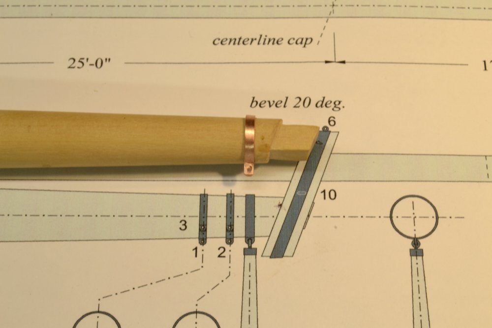
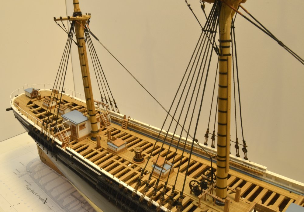
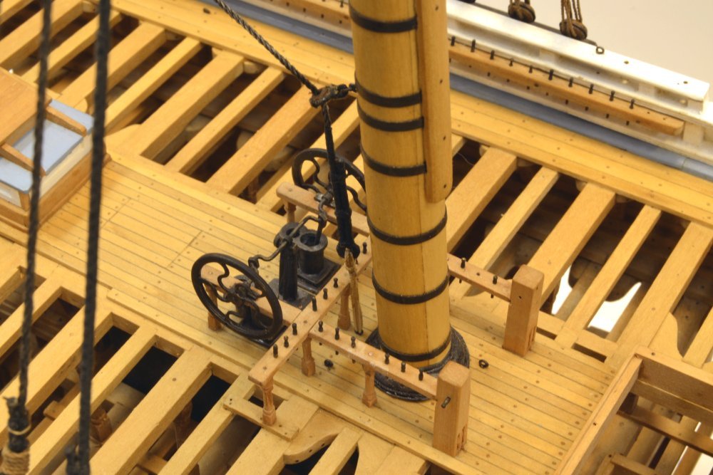
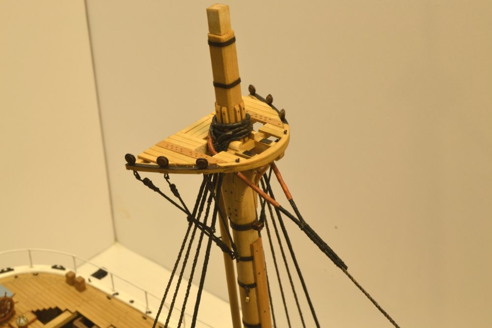
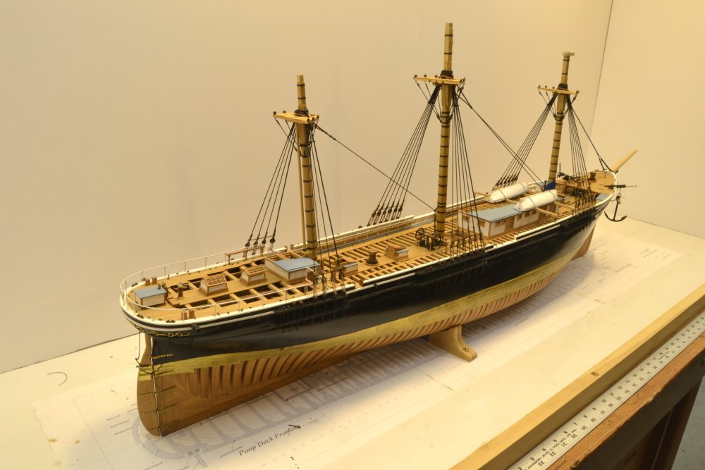
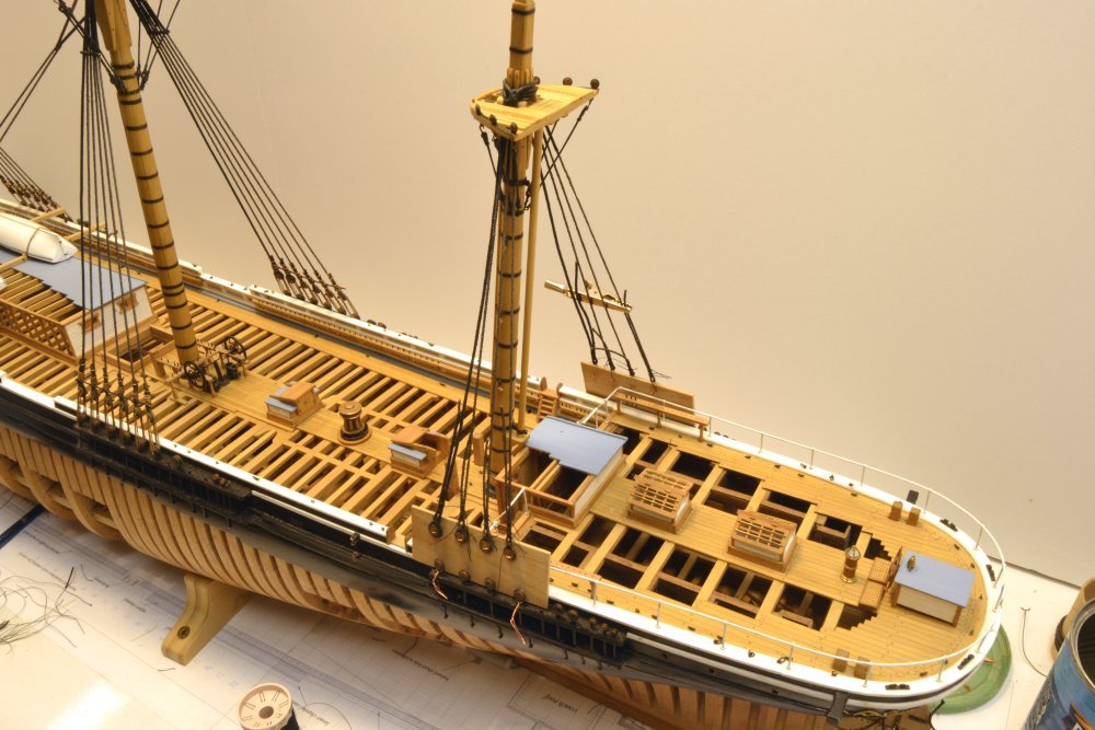
Young America - extreme clipper 1853 Part 212 – Mizzen Stay Before moving to the mizzen stay I had to replace the aft chain plate on the port side and make and dye some more 3½" lanyard rope. This went rather quickly and the mizzen shrouds were completed as shown in the first picture. The next picture shows the completed mizzen stay. The stay is looped over the shrouds at the mizzen top, fed through the lubber's holes on each side and secured with three round seizings. At the lower end it passes through a bullseye shackled to an eyebolt on the main mast and ends in a thimble secured by another three round seizings. This is lashed to an eyebolt in the deck. Again, because of the soldered shackle, the eyebolt/bullseye assembly had to be prefabricated. It was slipped over the stay as shown in the next picture, allowing the lower seizings to be done off the model and avoiding having to pass the leathering through the bullseye. The stay is roughly the same size as the shrouds, is served and leathered at the top, and served at the bottom. The lower seizings have been put on and a temporary thread is attached to secure the bottom while the masthead collar is secured. The next picture shows that collar. The next picture shows the lower end of the installed stay with the permanent lashing to the deck eyebolt. The last step in completing the lower standing rigging was to put leathering on the mainstay legs astride the foremast. I had forgotten to do this earlier. The next picture shows this painted wrapping. The last picture shows the model at the current state, with all the lower shrouds and stays installed. The next step will be to tackle the bowsprit, but I may begin some ratline work to help me spread out that tedious task. This will also allow me to make and fit the shroud fairleads. Ed

- 3,618 replies
-
- 40
-
-
- young america
- clipper
- (and 1 more)
-
Good point, Carl. Others may wish to comment. I believe stretching has some benefit, primarily on made rope, where stretching causes fibers in the multiple twisted strands to "bite" into their neighbors. This seems to "harden" the rope and neutralize residual stresses. A made rope that will tend to curl up after spinning will lie flat after stretching. I believe you are right that merely stretching rope or thread fibers, if within their elastic limit, will not have much effect and they will tend to return to their normal state. Stretching beyond that point will permanently effect the properties and that may be why a benefit is seen in pre-stretching. This is my amateur, armchair analysis. Rope material properties for model rigging is an interesting topic and is fraught with opinions (like mine) relating to strength, sagging, stretching, etc. I probably have an overly paranoid view regarding the properties of cotton and therefore prefer linen where tension is expected and needed - like standing rigging. Linen fibers are harder and stronger. Against this admitted prejudice is the experience many highly respected and more expert builders who routinely use cotton. Today, the debate is largely academic, since suitable, high quality linen is virtually unavailable. I still have enough old stock to handle the standing rigging on YA, so that is what I am using. The rest will be long staple crocheting cotton. I do not use any stiffening agents on lines before rigging. This opens the topic of moisture protection which I will try not to enter at this stage. Waxing of line is widespread and I may apply a wax solution later. I am still thinking about this. Wax collects dust and wax crystal (eg beeswax) can look like dust. I plan some experiments with micro-crystalline wax solutions later. Ed
- 3,618 replies
-
- 8
-
-
- young america
- clipper
- (and 1 more)
-
Yes, I pre-stretch everything - on the rope walk after spinning - almost to the breaking point - then hold 5 seconds. Again after dyeing. Well, I don't stretch that black cotton I am using for serving and small seizings, but virtually everything else. Ed
- 3,618 replies
-
- 3
-
-
- young america
- clipper
- (and 1 more)
-
Thank you all for the comments. It is good to be back at work - even considering the broken chainplates. Dirk, what's not to like about clippers - sleek, majestic, graceful ... Carl, I tensioned the deadeyes by gently pulling one one leg at a tine - up in the inside and down on the outer legs. The horizontal alignment of the deadeyes is set by the length of the shrouds when the deadeyes are turned in on the fixture. Of course the tension needs to be relatively equal to keep the alignment. I did the first tensioning before lashing on the sheer poles and the final tensioning after - alignment can be refined by tension. There are two other issues. One is twist. This is eliminated by the sheer pole lashings. The other is tilting of the deadeye in or out - off the vertical - this can be fixed by pulling on all three out lanyard legs at once. this will cause the deadeye to incline in or out. All these adjustments are very slight. There is one other issue that I believe relates to the stiffness of the linen lanyards. They do not stretch - at all. So, it is very hard to get them taut enough to be perfectly straight. Cotton would stretch a bit and look straighter. I decided on linen for strength and sag resistance. It can take a lot of tension - enough to require strong chainplate joints. I may be overly concerned about cotton stretching, but the difference in stretch is pronounced. Druxey, I have had to replace a few chainplates (maybe 5 of 60). The silver-soldered joints below the deadeye are very small. I believe the problem is overheated joints, causing brittleness, causing breakage from excessive working. The small percentage of breaks seem to occur where deadeyes have been worked back and forth after installation - straightening, adjusting deaedeyes, etc. Otherwise the joints are quite strong. Fixing them is a pain, but I made the channel slots large enough to pass the lower eyes, so that helps. Ed
- 3,618 replies
-
- 8
-
-
- young america
- clipper
- (and 1 more)
-
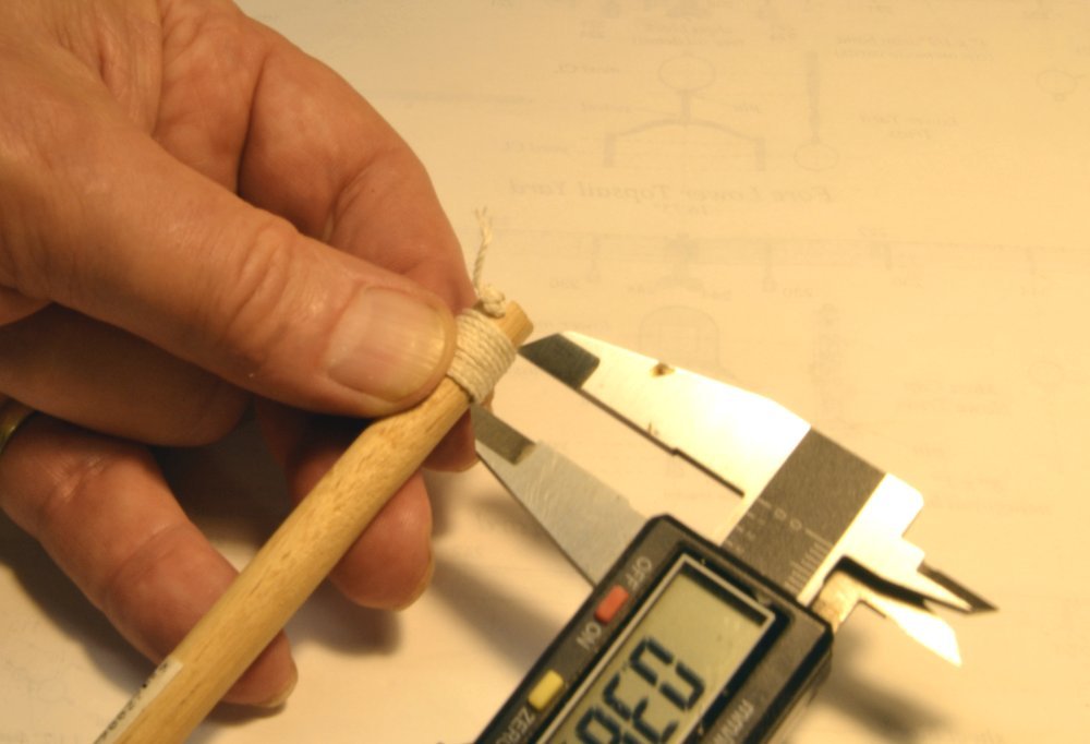
Young America - extreme clipper 1853 Part 211 – Mizzen Shrouds It has been over two months since the last post on Young America. At that time I had forecast an interruption in the shop for other work of about two weeks. So much for project scheduling. At the end of April, the shop had to be cleared out for some dusty, full-sized woodwork – the restoration of an ornate, rotting garden arbor, construction of a large, paneled garden gate, and the resizing of an old, 3'10" wide bed to a standard single. This work, plus a number of other things, kept me busy and kept the model safely stored in another room. I got back to work about a week ago. Over the past week, work has been focused on the lower mizzen mast rigging. The mizzen shrouds are 8¼" rope. As with the other standing rigging, I spun this from linen thread – three doubled strands of relatively fine size. I believe I mentioned earlier that I wanted to avoid getting into a rope making discussion here. There is much to be said about this subject – from theory to practice to modeling - that I think I will leave to Volume III of the book. However, I will mention one key aspect – measuring of threads and made rope. Regardless of the rope making method used, measurements are needed and obtaining consistent, accurate results is difficult. The method I use is shown in the first picture that shows some mizzen shroud rope diameter being measured. While I am sure others have used this simple method, I find it to be very consistent and fairly accurate. Ten turns are wrapped around a dowel, closely spaced. The width of the turns is then measured as shown and divided by ten to get the rope diameter – in this case .036" – close to the diameter of the 8¼" circumference rope required at 1:72. Having made the right size rope for the shrouds, it was ink dyed and cut to lengths required for each pair. These were then served, parceled at the masthead, and seized, as shown in the next picture. In the picture the parceling has not yet been "tarred" and the excess seizing thread ends remain. In the next picture, the ends have been clipped, black acrylic color has been applied to the parceling, and the first pair on the starboard side pushed down over the masthead. With all four pairs mounted, thin wood fixtures were made to hold the upper deadeyes for seizing to the shrouds. This was discussed in an earlier post. In the next picture the deadeye spacing is being marked on the port fixture. The next picture shows all eight deadeyes seized to their shrouds – still mounted on the fixtures. Lanyards for these shrouds were 3½" rope – again linen, made from three strands of the finest size. The next picture shows the deadeyes on the port side threaded up and being tensioned before wrapping and seizing the ends to the lower shrouds. Deadeyes were threaded by alternating sides, then given an initial tensioning. The picture above shows the final tightening after the sheer pole was lashed above the shroud throat seizings. The two aft lanyards have been wrapped. The last picture shows the lanyards wrapped and seized with their tail ends at the back of the shrouds. I made five turns as a standard on the model and tried to make them neat. In practice these were less aligned and wrapping continued until the rope was used up. The starboard side remains unfinished. Two reasons: in rotating a deadeye, a chain plate broke and had to be replaced; then I ran out of 3½" rope and will need to make more to finish the last deadeye. I hope then to move on the mizzen stay. Ed
- 3,618 replies
-
- 36
-
-
- young america
- clipper
- (and 1 more)
-
Looking great as usual, Gary. Sorry, I have not been following very closely lately, but my chore workload is lightening up so my browsing level is increasing. Those stern timbers look really good - and thanks for reinforcing the recommendation to use softwood for spacers. Sometimes these useful ideas get submerged in the volume of text. Ed ps. the term for the sweep of the deck is "sheer", as in "sheer of the deck", the same as used for the more pronounced curve of the external curve of the wales and planking.
-
Looking great as always, Frank. You can certainly tell that structurally she was built for the bay and not the horn. Beautiful clean work. Ed
-
Congratulations on the display and honor, E&T. Well deserved. Ed
- 346 replies
-
- 3
-
-
- terror
- polar exploration
- (and 2 more)
-
Thank you, Pete. Keeping dust off photographic negatives is probably a much bigger challenge than the level of cleanliness needed for models, but dust is ever-present in any woodworking operation. Hopefully you don't do sanding in your darkroom. Some years ago, I installed central dust collection in the shop with connections to the dust producing tools and this was a major improvement, but complete control, especially when work like power sanding, routing, sawing, etc are done. Hence the need for the dust case, which serves the purpose when the work is limited to modeling. For the heavier work I have been doing lately, I move the model out of the shop. As a side note, I am told that the new volume on Young America is in the bookbinding process and should be shipping around June 20. Orders are now being taken on the Seawatchbook.coms website. I expect to be back on the job in the next few days - making progress on the masting and rigging that will be the subject of Volume III. Ed
- 3,618 replies
-
- 11
-
-
- young america
- clipper
- (and 1 more)
-
Making chain, Allan? I don't think so. Hope to be back at it soon Sailor. other projects taking longer than anticipated - as usual. Ed
- 3,618 replies
-
- 3
-
-
- young america
- clipper
- (and 1 more)
-
Thanks, Bob, for the notice. I've been expecting it but have not had any specifics on the release date and do not have one yet. Hope you enjoy it. And thank you, Allan. Finding chain is a challenge. Here is a link to the source I used for some of the sizes - including the studded anchor chain: http://www.cornwallmodelboats.co.uk/acatalog/caldercraft_modernchains.html All the best, Ed
- 3,618 replies
-
- 3
-
-
- young america
- clipper
- (and 1 more)
-
Thank you Sailor, Steve and all who have commented since my last post. It is very difficult - perhaps I should say impossible - to include studding sail lines without the sails so I will not be including any studding sail rigging except the jewel blocks, etc. that would most likely have been more or less likely permanently fixed to yards, caps, etc. There is no doubt that studding sail lines - and even more commonly used lines - would have been doubled up on pins. There is just not enough room for that many pins. Especially aft. Should be back in business soon after completing some springtime and deferred "large-scale" woodworking projects. Cleaned out the shop today and hope to bring the model back in by the weekend. We'll see.
- 3,618 replies
-
- 7
-
-
- young america
- clipper
- (and 1 more)
-
Great work, Gary - one of my favorite parts of the model. Ed
-
Interesting process on the planking bolts, Frank - and a lovely result. I've been AWOL from the posts lately, but hope to be catching up soon. Ed
-
Nice work on the small boats, Nils. It is always interesting to see innovative solutions for modeling small scale pieces, and especially when many copies are needed. You have both these issues to conquer on your model and the results are great. Ed
- 2,625 replies
-
- 2
-
-
- kaiser wilhelm der grosse
- passenger steamer
- (and 1 more)