EdT
-
Posts
2,214 -
Joined
-
Last visited
Content Type
Profiles
Forums
Gallery
Events
Everything posted by EdT
-
Thanks, everyone. I really appreciate the comments. No secrets, Micheal. I'll include a picture or two in the next post, when I do the coat for the main mast. Basically just tissue, paper, some rope, glue and some tar (ie black artist acrylic). Maury, the short answer is I do not know the specific reason for cabins. I might speculate that rope would be subject to constant rubbing and potential failure as these 30' boats shifted back and forth. These ships were equipped for the Cape. As to the reference, I undoubtedly saw this in a photo and it stuck. If I come across it I will report. Greg, I had in my mind that it was 2 1/2 years. It actually feels like about 1 1/2. Question is, how many more will it take? Ed
- 3,618 replies
-
- 6
-

-
- young america
- clipper
- (and 1 more)
-
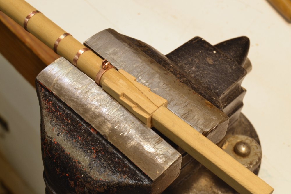
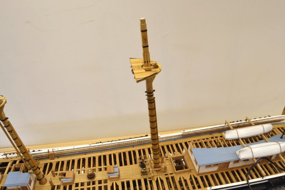
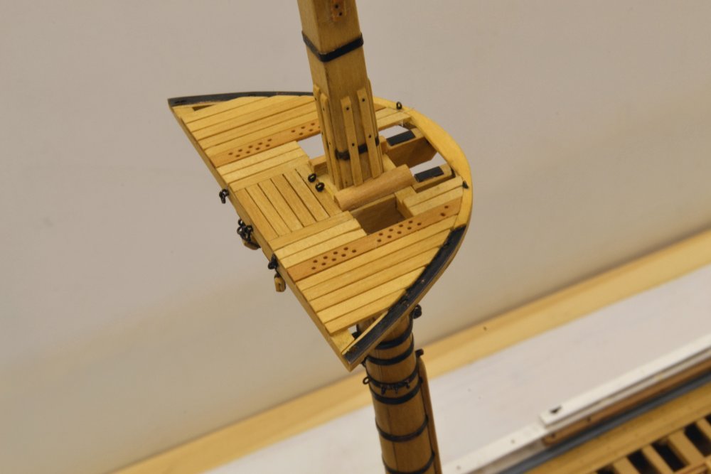
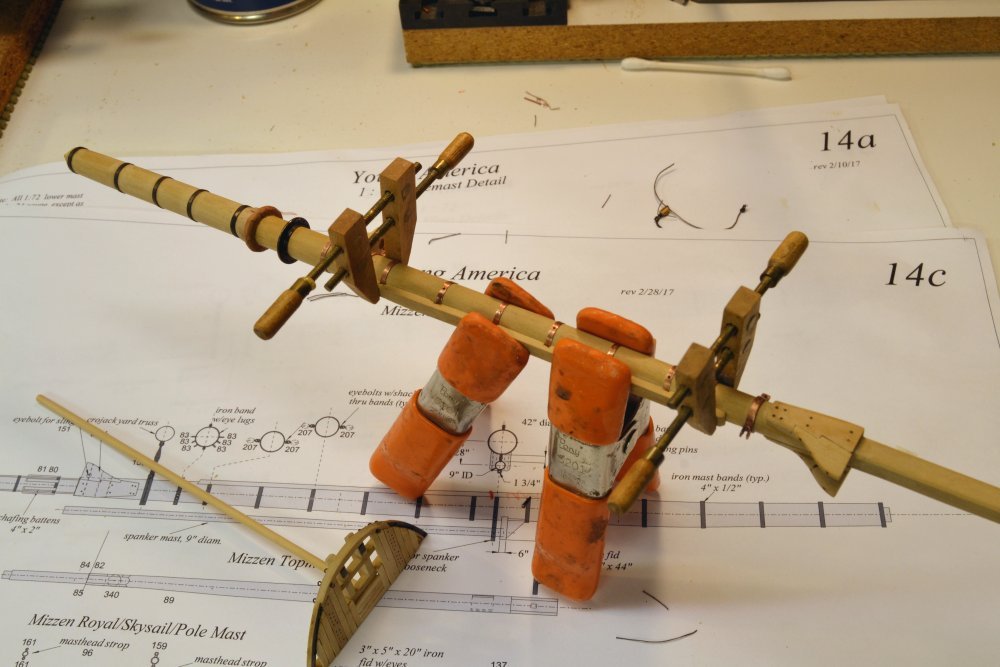
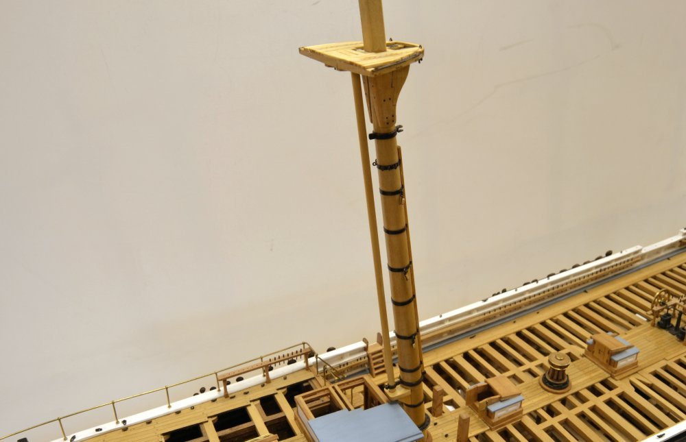
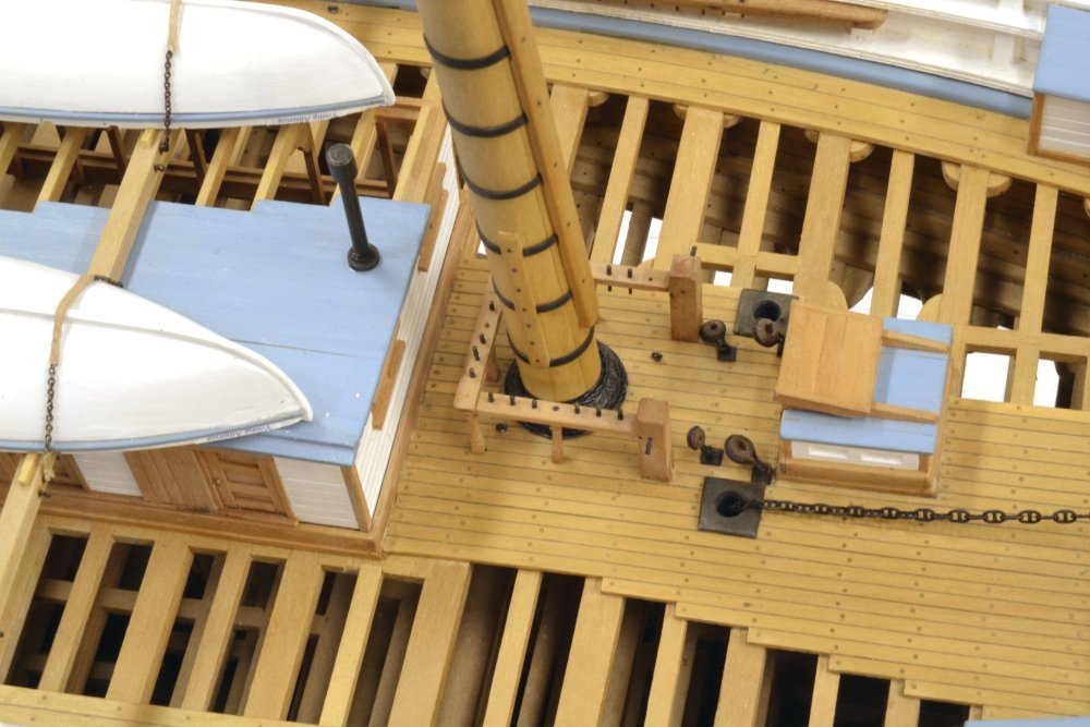
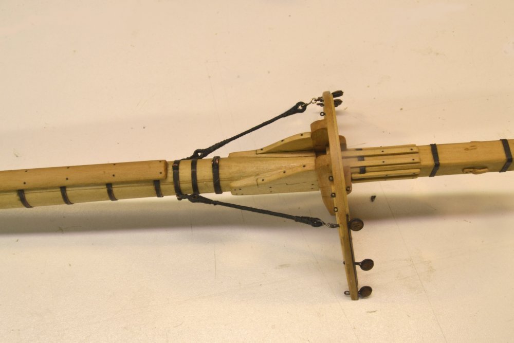
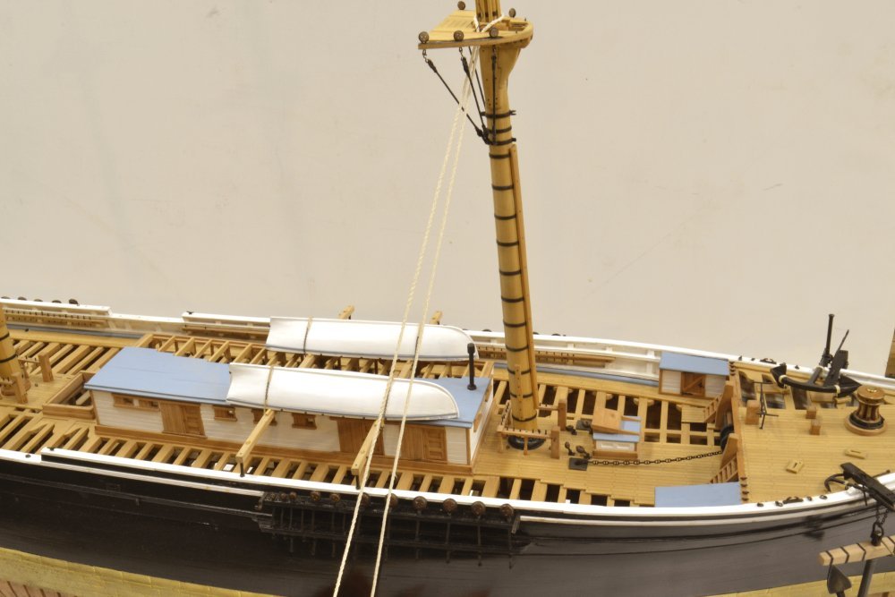
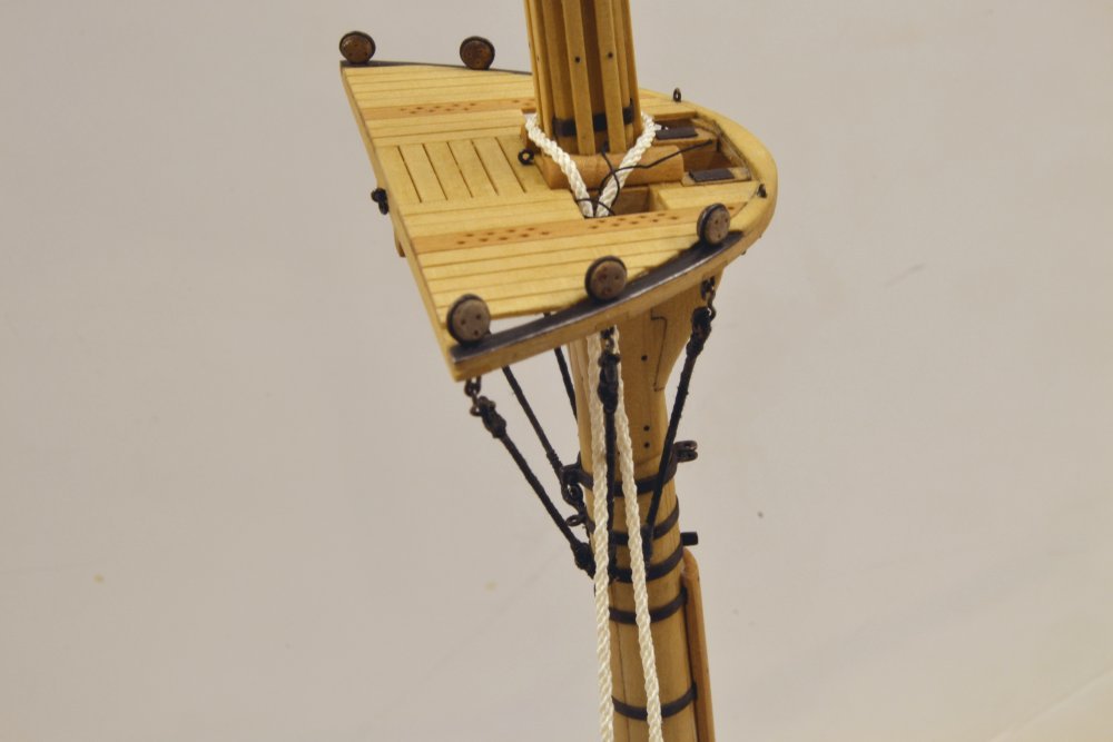
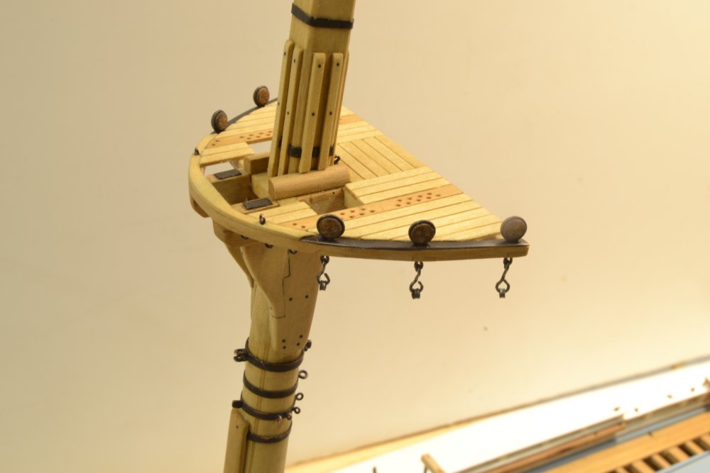
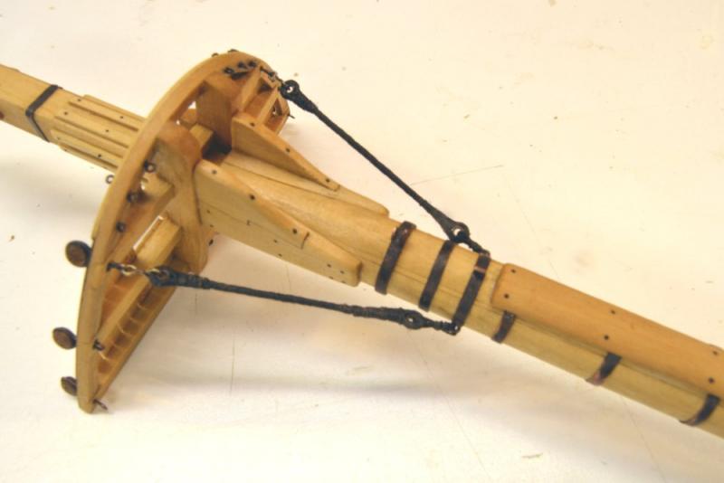
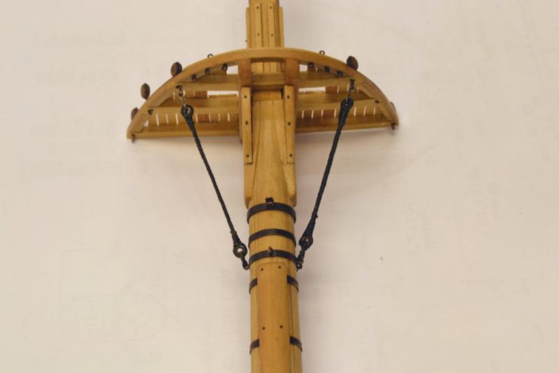
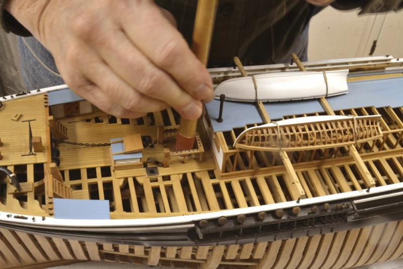
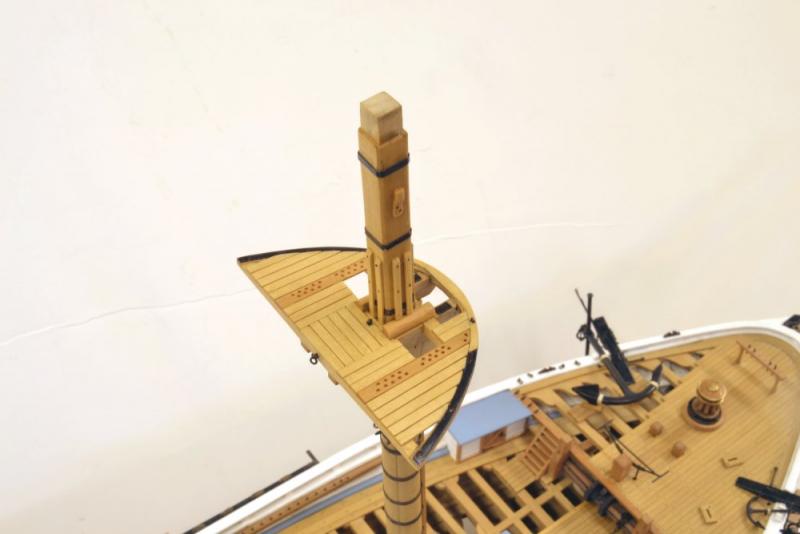
Young America - extreme clipper 1853 Part 200 – Lower Masts Continued It is hard to believe we are at the 200th post on Young America – almost 3 ½ years into the project. Still as exciting as ever – for me at least. Since beginning work on the lower masts, most of the reporting has been on the fore mast – the guinea pig for construction, finishing and rigging – and only one version in the scrap box. However, though mostly unseen, work has been proceeding on the other two, so here are a few pics. The first is the most recent, taken yesterday and showing the main mast ready for fitting the deadeyes and rigging the futtock shrouds. The mizzen mast to the left is almost to the same state, but needs its masthead detailing. The next picture shows the main top before fitting the deadeyes. At 18' 6" in breadth, this is somewhat larger than the 17' fore top. The "pre-rigging on this top includes a pair of brace blocks for the mizzen lower yard, the crojack. These may be seen dangling from shackles below the aft crosstree. Because of the soldered shackles, any shackled connections, including eyebolts, need to be either fitted with their blocks or left off until later. The next picture shows the forward chafing batten being glued to the mizzen mast. The batten is concave on the mast face and was rounded on the forward face after gluing. The top, with the 9" diameter spanker mast inserted, is to the lower left. The below-deck rings have been blackened and the ring of wedges is in place. After this step the above deck ironwork was buffed with a clean wheel and blackened as shown in the next picture. The sanding stick in the picture was used to clean the glue off the batten's nail heads (not shown). The next picture shows the mizzen at this stage. The top and the spanker mast are permanently attached in this picture. The picture also shows small brail blocks hanging from the mast. These will be discussed later. By this time, the foremast was complete and could, if desired, be permanently installed. The last picture its base with a mast coat fitted over the wedges. The mast coat simulates a tarred canvas cover with surrounding rope to pull it tight at the mast and at the base. It would also have been nailed before tarring. I could find no standard method for these – only brief and varied descriptions. Ed

- 3,618 replies
-
- 43
-
-
- young america
- clipper
- (and 1 more)
-
Bravo, Amalio! Ed
-
Rob, as I said in the last post, the shrouds are given an initial tension - after hooking - by the lashings at the mast. These lashings consist of 6 turns of small rope that allow the shroud to be pulled straight when they are hauled up. the lashings are then secured by wrapping the rope around the turns and securing it. Although visibly straight at this stage the futtock shrouds will not be put under tension until the topmast shrouds are tensioned and secured using their deadeye lanyards. The deadeye straps have a sliding connection at the rim of the top so that this tension can be applied from the topmast head to the lower mast eyes through each futtock and shroud. If either shroud were fixed at the top, that light structure would be subject to failure from bending forces at the rim. With the sliding connection at the rim the top cross trees are only subject to horizontal compression. Clear? Ed
- 3,618 replies
-
- 3
-
-
- young america
- clipper
- (and 1 more)
-
Rob, The specified shroud size is now 5 1/4" (actually closer to 5.5" model rope) and the deadeye size is 9". Rule of thumb is 1.5X, but sources show 9" up to 10" for these. The hooks are not adjustable. The futtock shrouds are given an initial tension by the lashings at the mast, but the real tension in the futtocks will be applied when the lanyards on the topmast shrouds are are hauled up. The lower shrouds will be paired 1&2, 3&4, 5&6, which I believe is standard. Ed
- 3,618 replies
-
- 5
-
-
- young america
- clipper
- (and 1 more)
-
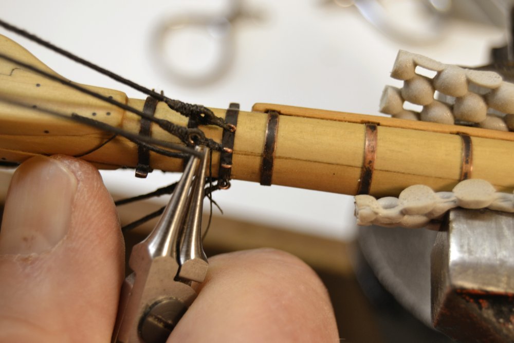
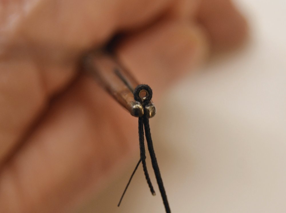
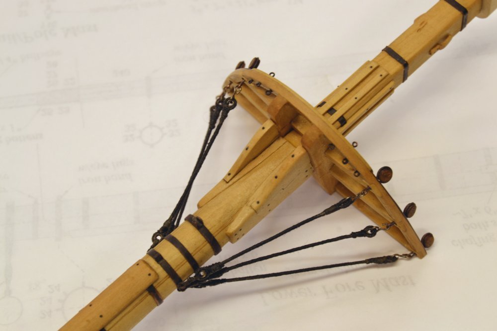
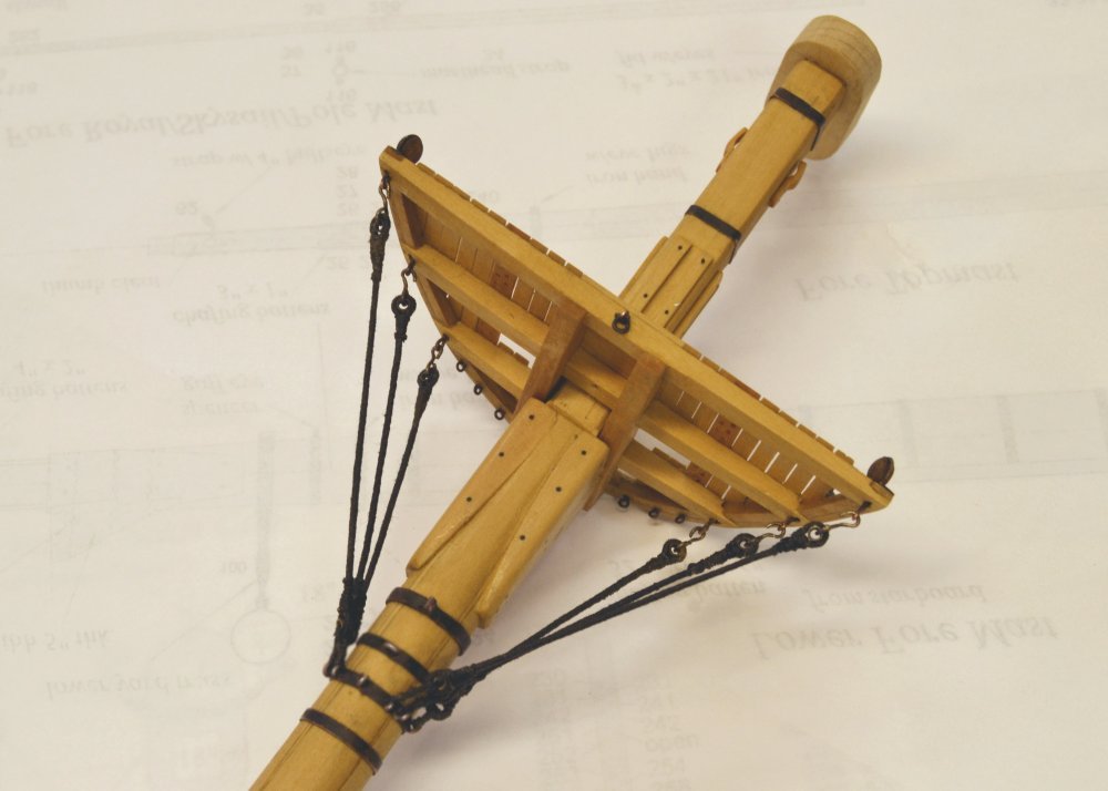
Young America - extreme clipper 1853 Part 199 – Setting up Futtock Shrouds The lower futtock shrouds are lashed to mast eyebolts as shown in the first picture. The picture shows the first two secured. Before lashing the lower ends, eyes and thimbles had to be worked into the shrouds with the lengths set to provide relatively consistent lengths to the lashings. This was done by hooking each shroud to its deadeye strap and then grasping the rope at the desired length with round tipped pliers as shown in the next picture. The rope was then looped over the jaw to set the position for the eye. This picture demonstrates the problems caused by a lot of handling of the masts after blackening of the copper ironwork. All the ironwork on the masts was retreated after all the pre-erection detailing – as will be seen in later pictures. The next picture shows an eye with the thimble inserted with glue applied at the splice joint – as described in the previous post. The next two pictures show the six futtock shrouds installed on the lower fore mast. The ironwork has been mostly re-blackened in these pictures. The next two pictures show a test I felt compelled to make to satisfy myself that the lower shrouds would clear the futtocks. I felt some trepidation about this, not knowing what I would do if there were interferences. Fortunately there were none that miniscule movement of the collar could not cure. The next picture shows the positioning of shrouds 3 and 4 that straddle the center futtock. The white rope used in the picture is some reject 4-strand linen rope that approximates the size of the served 10 ½" shrouds. The uneveness reflects the difficulty of making four-strand rope without a central core. The foremast is now ready for installation and work is proceeding on the other two. In the next to last picture a mast coat may be seen at the deck covering the wedges. This will be described in the next part. Ed
- 3,618 replies
-
- 37
-
-
- young america
- clipper
- (and 1 more)
-
Frank, somehow I missed commenting on the finale. It came upon us so fast. A beautiful result showing what skill and meticulous attention to detail can do - to say nothing of the thoughtful process development. Great work, an example for us all. Ed looking forward to the skipjack build.
- 649 replies
-
- 6
-
-
- dunbrody
- famine ship
- (and 2 more)
-
Thanks again, everyone for the comments and likes. The progress is slow these days - half development, half production. Rob, I have no plan at present to complete the 1:96 version of the model. It was always intended as a demo piece for describing a POB type hull for Volume I the book. I wanted to include that simpler, smaller version for modelers not wanting to build to big version or not wanting to go fully framed. Methods used at 1:72 may also be used, with some exceptions, to complete the 1:96 model. There may be fewer opportunities to use details like thimbles for example, but judging from the abilities I see demonstrated on this site, I have little doubt the many could scale down all the details used on the 1:72 version. Volumes II and III will will support either scale, including drawings for both. Micheal, thanks for your comments on scale. Much of the work is very small, perhaps too small for my aging fingers that seem to grow in size and become less cooperative with each passing year. EaglzEyes, I like questions even if I cannot answer them. Ed
- 3,618 replies
-
- 7
-
-
- young america
- clipper
- (and 1 more)
-
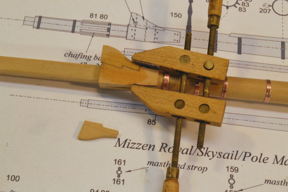
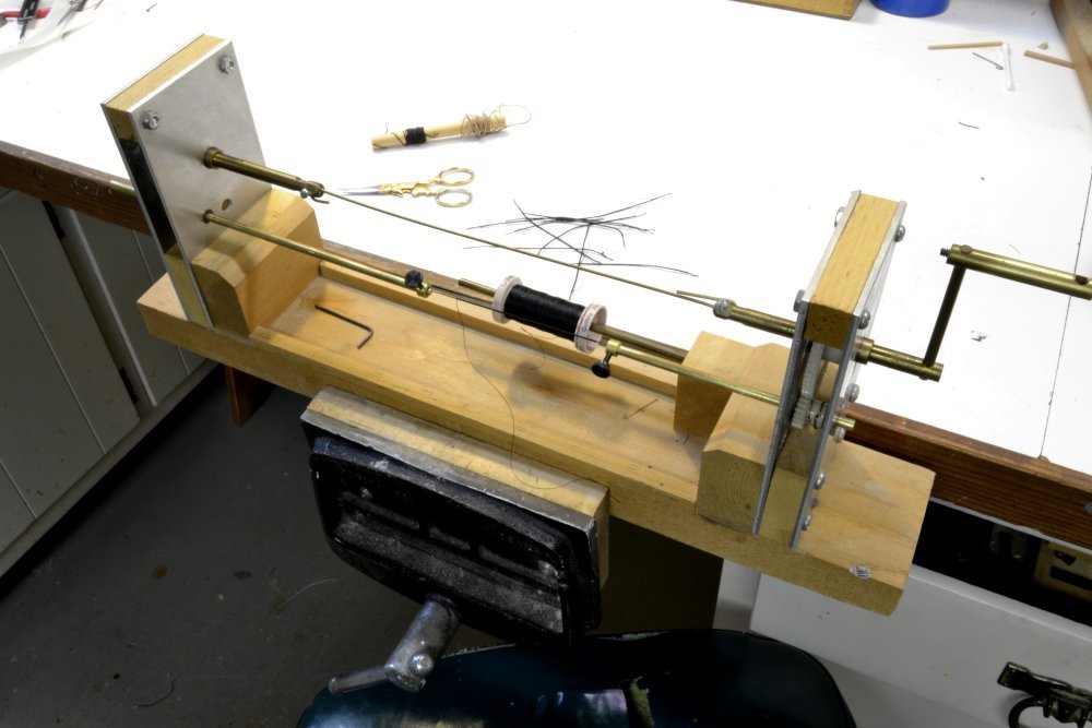
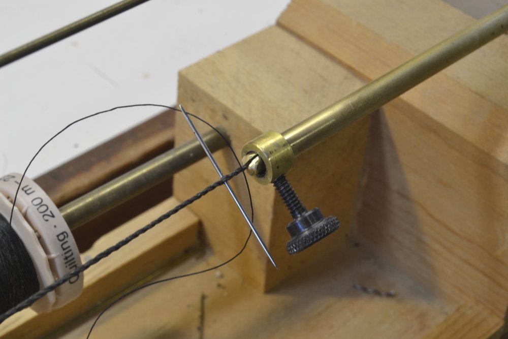
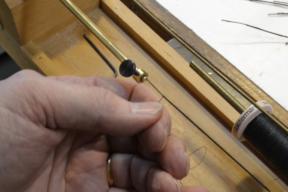
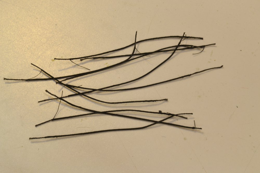
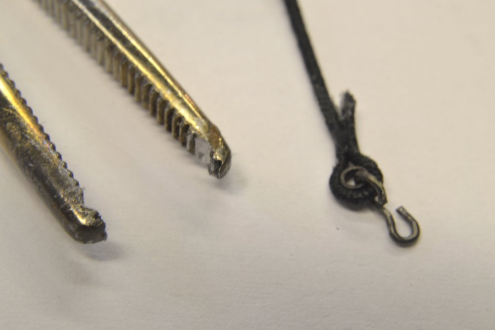
Young America - extreme clipper 1853 Part 198 – Making Futtock Shrouds The lower futtock shrouds on the fore and main masts are 5 1/4" rope (meaning the circumference is 5 1/4"). This equates to a rope diameter of about 1 ¾", about .024" at 1:72 scale. The mizzen shrouds will be 4 ½". I used rope made from three strands of (.012" dia.) Barbour Irish linen suture thread for this. I hope to use linen for all of the standing rigging – if the sizes I have will work out and if my limited inventory of quality linen holds out. I like the hardness of the linen and its resistance to stretching for the taut standing rigging, but quality has deteriorated in recent years. I will forgo a discussion of rope making and sizing here, but expect to fully describe the process that I use in Volume III. Rope making methods and hardware have been well described in many sources. I find it to be more of an art than a science that can be described simply. I will instead start with the serving process. I made my serving machine ten or twelve years ago for my Victory model. It is shown, with some modifications since then, in the first picture. The machine consists of large crank-driven gears at each end connected with a jack-shaft as shown. These gears drive smaller spur gears in synchronization and at stepped up rpm. Rope is stretched between tubular shafts through the smaller gears. The next picture shows one of the crude collets that hold the rope. The rope passes through the tubular shaft, allowing long lengths to be fed through at the length needed. The picture shows the method I use to start the serving thread. A needle is passed between the strands and the thread pulled through. The thread used here is Guterman quilting cotton, a long-staple, fine cotton thread with virtually no fluff. It measures about .005" to .007" diameter, equal to about ½" at 1:72 scale. A bit thick perhaps for serving yarn, but considering that the actual rope would have been wormed and parceled before serving, not far off. After several turns are lapped over the short end, it is clipped off and the serving proceeds as shown below. The rope length between collets is adjustable by pulling the shafts through the spur gears then retightening the set screws holding the gears. The futtock shrouds are short. A more complete description of the process may be found in my earlier Victory log, here: http://modelshipworld.com/index.php?/topic/316-hms-victory-by-edt-196-pob/&page=2 A number of served shrouds for the main and mizzen masts are shown below. Served eyes of this large size are made from the served rope by wrapping it around the thimble and securing it with darkened Titebond glue. It is held together until well bonded using the surgical clamp shown below. The jaws of the clamp have been filed to form a round opening. The eye splice in the picture has been bonded through the serving by wetting the splice before applying glue. When fully dry, the short end is shaved back to blend with the rope using either a razor blade or very sharp scalpel. The joint from the thimble down to the end of the splice is then coated with glue and wrapped with serving thread as shown below. The glued serving reinforces the splice. Because of the (overnight) wait time for the Titebond to fully bond, I also tried CA on the splice with Titebond on the serving. The CA joint with the linen does not seem to be as strong as the Titebonded joint. I may need some more clamps. The opposite ends of these futtocks are spliced in the same way, but without hooks. Ed
- 3,618 replies
-
- 40
-
-
- young america
- clipper
- (and 1 more)
-
Thank you both for these comments. Tony, sorry for not responding earlier to your December post. I hope, if you decide to buy the books, that you will find them useful, whether you decide to give Naiad a try or not. My goal has been to bring what some would call advanced model building, down to a practical level for less experienced builders or those who may be intimidated or who doubt their skills. I hope you find them so. Ed
-
First time through your build today, Mike. Beautiful work. Picture perfect in every way. Ed
- 452 replies
-
- 4
-
-
- cheerful
- Syren Ship Model Company
- (and 1 more)
-
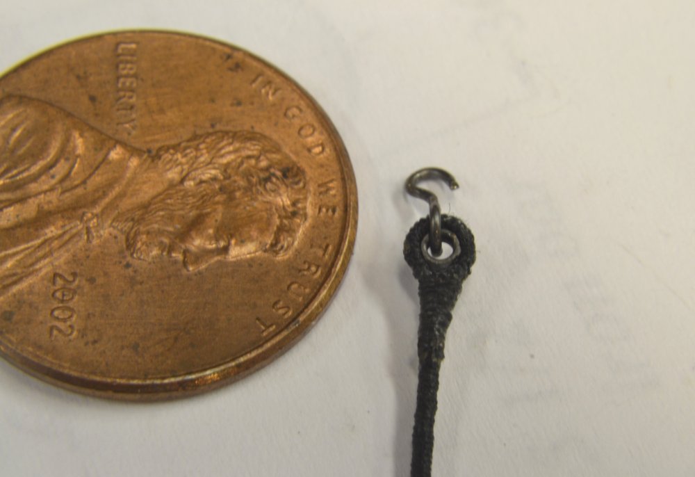
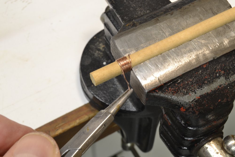
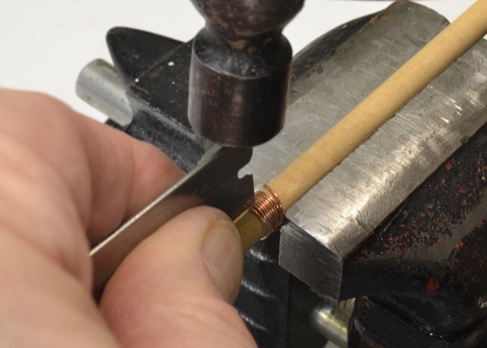
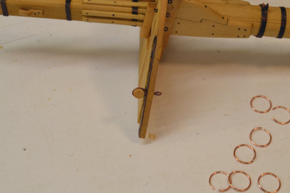
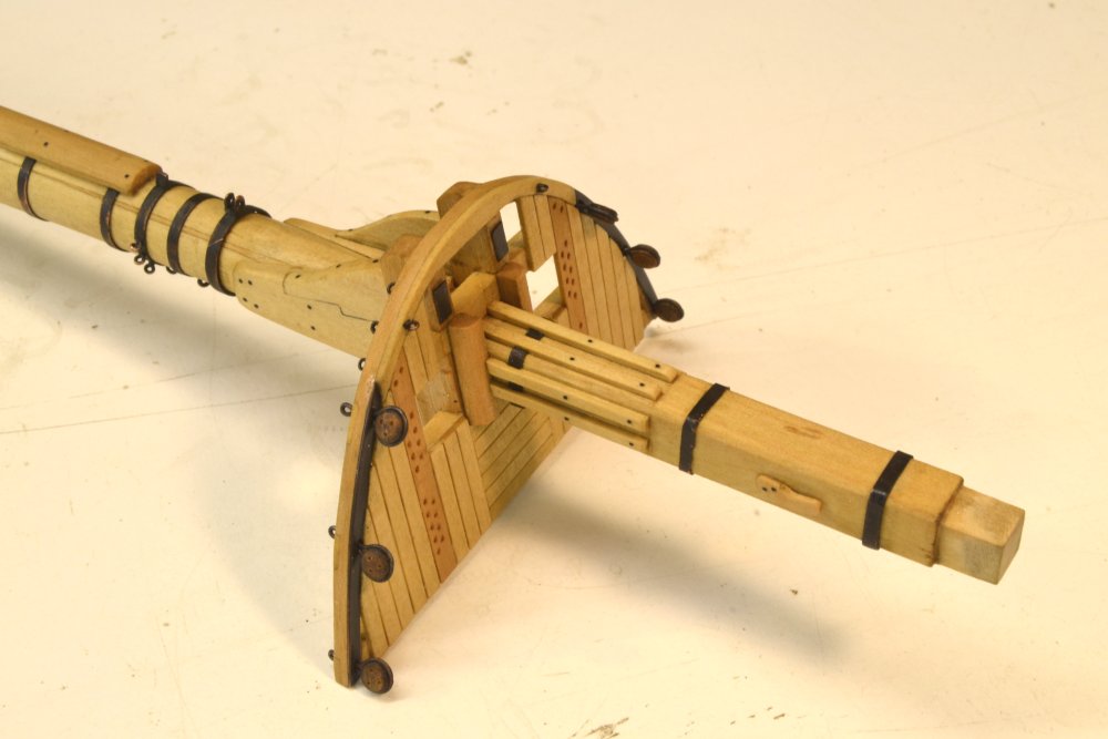
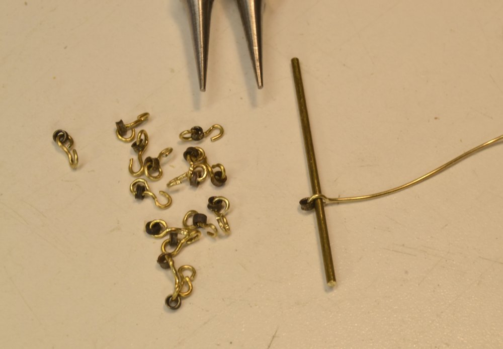
Young America - extreme clipper 1853 Part 197 – Topmast Shroud Deadeyes The last post showed the forward futtock shrouds installed, but was mainly concerned changes to rigging sizes, so I skipped over the work on the shrouds. This work started with making straps for the deadeyes from copper wire. The first picture shows wire wrapped around a dowel to make consistent-sized rings that will be formed into straps. After some testing of ring size, a ¼" dowel was determined to be the right size for this – conveniently. I was hoping to avoid turning a special size. After wrapping tightly, the rings were parted as shown below. The razor blade shown above makes a clean cut in the 22 gauge wire used for these – but only one or two at a time. The next picture shows some rings before soldering as well as the test assembly fitted into the top. The next picture shows the top with its six deadeyes fitted through slots in the iron reinforcing strip and the wood rim below. A variety of futtock shroud materials and methods of fastening were used during the period. Iron bars were coming into use. Where rope was used, connections might be shackles, hooks or lashings. Mast connections varied. I decided on rope with hooks at the top and lashings at the mast eyes, typical of the early clipper years. The next step was to make the hooked-thimbles. Some are shown in the next picture. These thimbles were cut from 1.5mm brass tube then flared by tapping with a shaped punch. The thimbles shown happened to be blackened first – not necessary. The eyes in the hooks must be large enough to pass the served shroud. To ensure this, the brass rod shown was used as a gauge when forming the hooks. In the last picture the hooked thimbles have been blackened and are shown suspended from the straps, awaiting connection of the shrouds, Making the shrouds will be described in the next part. Ed
- 3,618 replies
-
- 38
-
-
- young america
- clipper
- (and 1 more)
-
Great photo. Yes, wire sizes were a lot smaller. According to a table in S.B Luce, Seamanship 1868, comparing relative sizes of hemp, iron and steel, a 10 1/2" hemp rope was equivalent to 4 1/2" iron wire cable and 3 3/8" steel wire cable. Wire was well along in adoption in Britain in the 1850's but probably slower in America, but it was in use and there will be some on the Young America model. A 10 1/2" inch rope is quite large, but much smaller than Victory's 19" main stay! Hemp at 10 1/2" circumference had a working load strength of about 10,000 lbs and a breaking strain of about 64,000 lbs, according to the table in Luce. Merchant ships were not generally fitted with preventer stays so I assume Wavertree was a navy ship? In any event, for comparison, the American Lloyds spec for 1200 ton ship topmast was 9". On YA this will be a doubled stay. So, it is roughly in line with what you have shown. Thanks for this input. Ed
- 3,618 replies
-
- 7
-
-
- young america
- clipper
- (and 1 more)
-
Thanks, Druxey. Sometimes I long for the clarity of Steel and the Repository.
- 3,618 replies
-
- 4
-
-
- young america
- clipper
- (and 1 more)
-
Thanks for that information, Frank. I will pursue it. To my eye, WinOx instead of a selenious acid product produces a more grayish tone. I used that on the hook/thimble assemblies and the appearance is good - initially. Unfortunately, there is a lot of handling of the hooks in making and serving the eyes, so some of the oxide wears off. Some localized retouching may help, but the chemicals must be kept off the rope. I also tried the aluminum tube. This makes lovely thimbles very easily, but I am concerned about dissimilar metals and corrosion. I am testing a brass hook with an aluminum thimble in salt water. Not sure if there will be a conclusion from this. Thanks for the help. Ed
- 3,618 replies
-
- 5
-
-
- young america
- clipper
- (and 1 more)
-
Young America - extreme clipper 1853 Part 196 – A Touch of Rework This post was intended to be about topmast deadeyes and connection of those deadeyes to their futtock shrouds below the foretop. However, some interesting discoveries caused some rework that has interfered with this – and other work that was proceeding. Fixing mistakes is not all that interesting but in this case I learned some things that may be of interest and I'm not sure the term "mistake" applies. In any case the rework is relatively minor, and the final model will certainly benefit – though the change may be fairly obscure and unnoticed. The first picture shows the two forward futtock shrouds installed under the fore top. The shrouds in the picture have eyes with thimbles at each end, hooks to the deadeye straps, lashings to the mast eyes, and are served all over. After completing this work, I felt, perhaps intuitively, that the rope looked a bit heavy. I keep thinking of the lacy rigging in the photos. The specified size of the topmast shrouds on large merchant and Naval ships, and therefore the futtock shroud size, is 6 ½", a size that goes back in time at least to Steel, and probably earlier. It is repeated in other early sources, probably copying Steel. It is also listed in Underhill's work on clipper ship rigging that I have used for some line sizing. Crothers rigging drawings follow suit. Considering the slight exaggeration in diameter that serving at this scale causes, the final futtocks shown above measure about to the spec. In pursuing this further, I learned that American underwriters, at least, had some different ideas about standing rigging sizes. While they duplicate Steel for the most part, they part company in the way topmasts are supported. It appears to me that they wanted stronger topmast backstays and were less concerned about the size and structural importance of the topmast shrouds. Both the New York Marine Register of 1857 and the American Lloyds Register of 1867 required 10 1/2" backstays on the fore and main topmasts on ships of this class, against the 7" size found in Steel – and other derivative listings. This is equal to the lower shroud and stay sizes – the largest lines in the ship. Topmast shrouds and futtocks on the large masts go from 6 ½" down to 5 ¼". The next picture shows a smaller, 5 ¼" replacement futtock on the left with the original 6 ½" on the right. There is quite a difference, of course. If this were the only fix needed, it would hardly bear mentioning, but the backstays are another matter. Upsizing these means changing out a dozen channel deadeyes and chains. The fore and main deadeyes go from 13" to 16" and the mizzen from 9" to 13". No fun for Ed. The last check before deciding to proceed with these changes was to examine the photographs of the ship. While they reveal little on the futtock sizes, they clearly show topmast backstays and deadeyes comparable in size to the lower shrouds as anticipated from the underwriters' specs. Wow! This would have been easy to miss and I am delighted to have discovered it at this stage. The difference will certainly be noticeable on the model. Other American clipper modelers take note. So, I will probably spend a week on the channel deadeyes and backstays – on the model, on the drawings, on the rigging list, and on the channel deadeye chapter in Volume II. Please do not comment on my sanity. Ed
- 3,618 replies
-
- 26
-
-
- young america
- clipper
- (and 1 more)
-
Thanks everyone for the comments and likes. Carl, theoretically glue would not be necessary, but relying on wedges alone on a model of this scale is risky, so as with many other attachments on the model, glue is the sensible choice. The glue will not only keep the masts down, it will also prevent rotation. If the question is: why glue the wedges to the masts, it is to permit the masts to be withdrawn and replaced as necessary until they are permanently fixed. If the wedges were glued instead to the partners, the mast rings below the deck would not pass through the opening. Also, the mast coats would have to be applied in place, within the confines of the fife rails. Cheers, Ed
- 3,618 replies
-
- 11
-
-
- young america
- clipper
- (and 1 more)
-
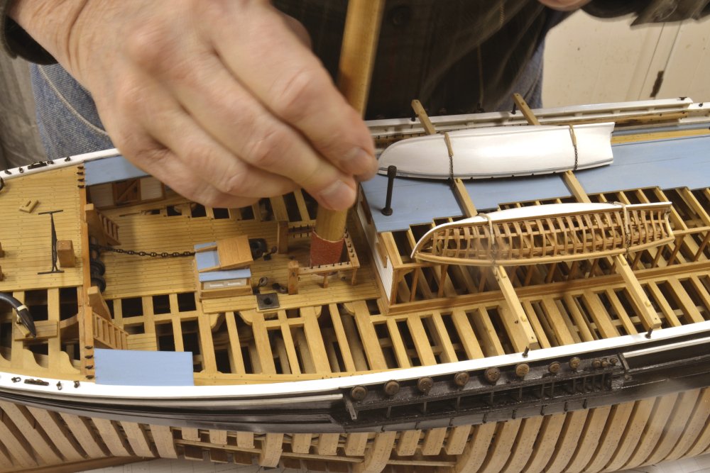
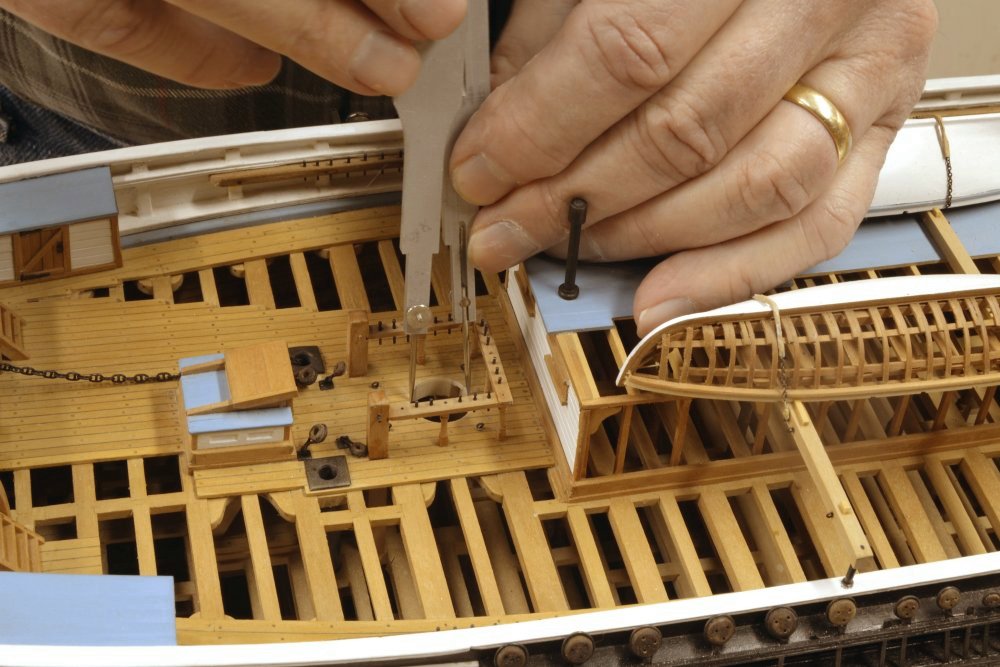
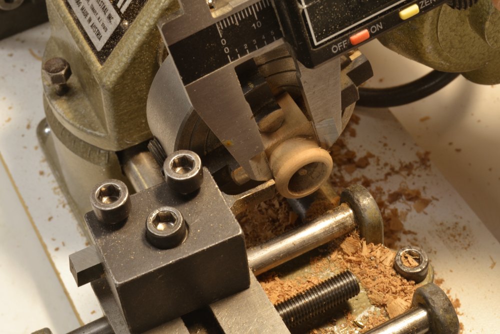
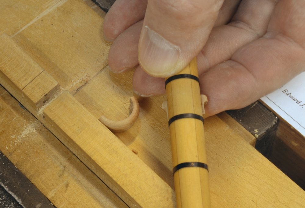
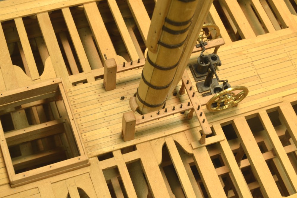
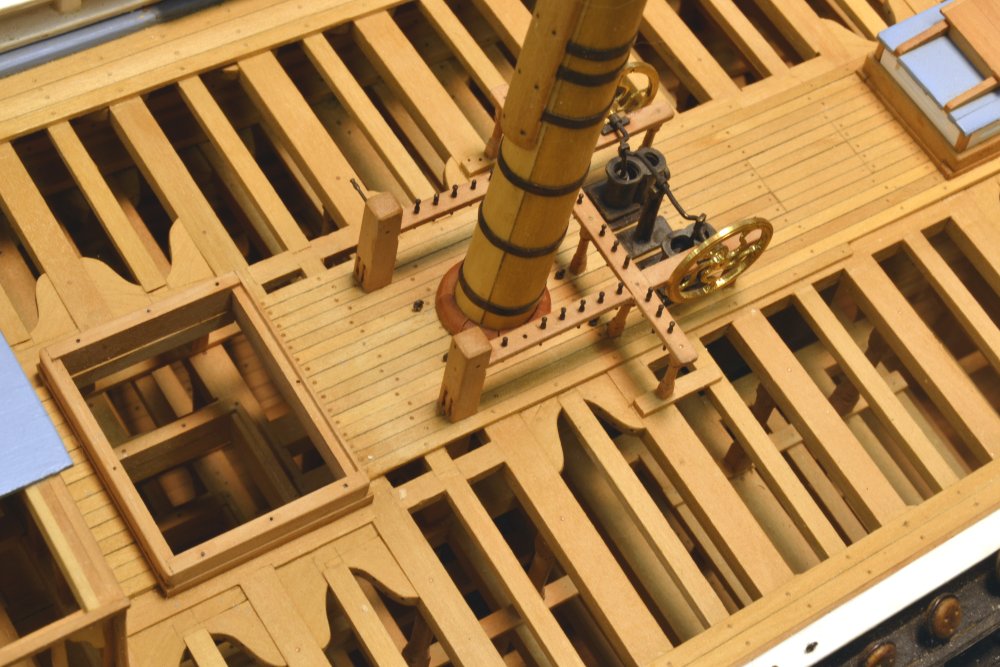
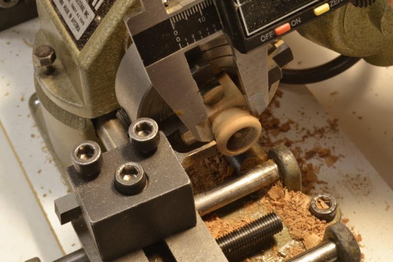
Young America - extreme clipper 1853 Part 195 – Mast Wedges So far, the masts have been temporarily stepped and placed in position through partners at the main deck level. The openings at this level were centered so the masts would stand at roughly the correct rake, but were not sized precisely, nor were they cut perfectly round. The next step in the mounting process was to fit wedges on to the mast at the partner level. The wedges would secure the masts at the correct rake, but still allow them to be removed for the remaining bench work. The first step was to size the openings, refine their position, and make them round – with a few inches of clearance around the mast. The first picture shows this being done at the fore mast partners, using sandpaper mounted on one of the tapered mandrels described earlier. When the opening was large enough to wedge the mast, the diameter was measured with dividers as shown in the next picture. In the next picture a ring is being turned that will fit the mast diameter and the hole diameter below an enlarged and rounded section at the top. The mast wedges were cut from this ring. The next picture shows the turned ring cut in two and one half being checked for fit on the mast. Each of these halves were cut into segments. In the next picture a segment has been fitted to the mainmast mast and the mast positioned. This allowed the mast rake to be measured and any corrections made before fitting the rest of the segments. The next picture shows the main mast with all the segments glued to it. Once wedged, the masts are held firmly in their final position but may be removed for further work. This work includes final installation of the tops and the masthead trim. It will also include installation of the deadeyes and futtocks for the topmast shrouds. The last step before finally stepping the masts will be the fitting of mast coats over the wedges. These will cover the woodwork shown above with simulated tarred canvas. The masts will then be glued at the partners and the step and will be ready for the lower shrouds. Ed


- 3,618 replies
-
- 33
-
-
- young america
- clipper
- (and 1 more)
-
Again, thanks to all for the comments, questions and likes. Maury, I usually dilute oil with mineral spirits. What I am using on the masts is probably about 50%. I normally use pure Tung, which is pretty viscous. Tung oil "finishes" may be partially polymerized or have other constituents, like dryers, added. This makes them easier to use. Some of these products may be thinner. I was just looking for a thin seal coat on the masts so was not too particular. I could easily have substituted Watco (linseed) - also thinned. Linseed is not as durable as Tung. All this will later be waxed. Ed
- 3,618 replies
-
- 4
-
-
- young america
- clipper
- (and 1 more)
-
Thank you all. Comments like these make my day - and so far it looks like its going to be dreary. I hope I got them all at this stage, Druxey. The two eyebolts above the forward rim were late additions - on the ship and the model. These will anchor tackles that were added with the second set of topsails. You're right, Greg, a lot of holes - as many as I could cram in and only one or to unassigned spares. Six yards on each mast required a lot of lines. At the rate these ships generated cash, a large army of riggers could easily be afforded to shave weeks off of the schedule. Unfortunately I have just one set of fingers, so yes, it is going to take some time. These builders could accomplish amazing feats. John Bertram, an 1100 ton extreme clipper was launched at East Boston just 61 days after laying her keel in 1850. Rob, the large eye for the lower yard chain sling under the top is conspicuously absent. Because it will be shackled to both the mast eyebolt and the yard band, and because these shackles are silver soldered, the sling with its eyebolts will be prefabricated. The location of the eyebolt hole will be placed with the yard on its truss so the chain will be taut and the truss horizontal. I do not trust my ability to measure the chain/shackled length and place the bolthole at this stage. This design does not require chain to be looped over the masthead, so hence no cleat on the aft face.. Ed
- 3,618 replies
-
- 7
-
-
- young america
- clipper
- (and 1 more)
-
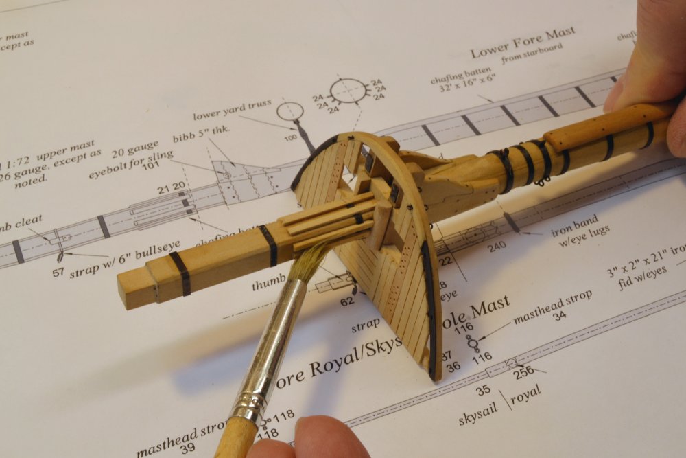
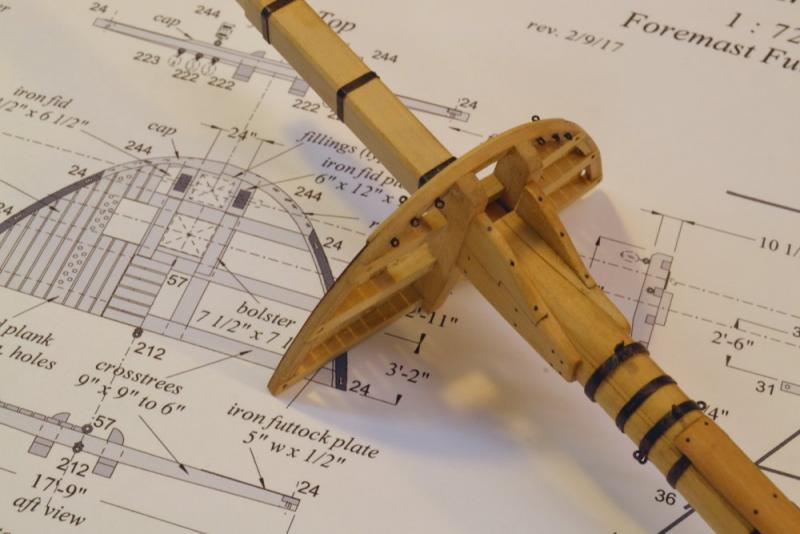
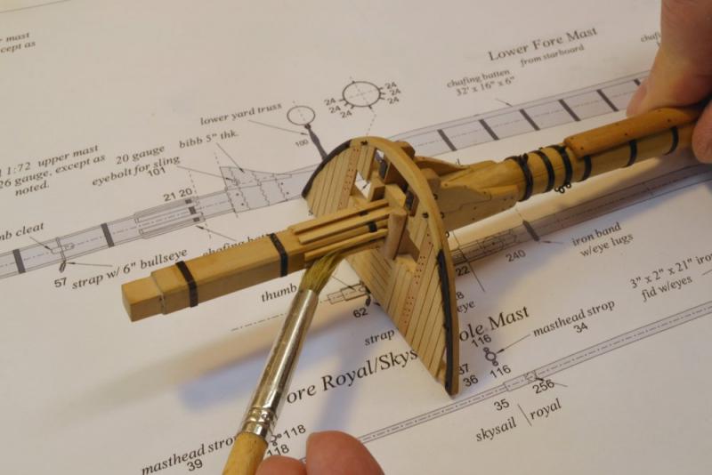
Young America - extreme clipper 1853 Part 194 – Lower Masts continued Previous posts showed the fore top completed and the other two constructed but not yet fitted with rigging connections. None had yet been installed on the masts, which remain loose from the model. The plan is to complete construction of the lower masts, then fit the tops with chains, deadeyes and futtock shrouds and then permanently step the masts. The mizzen mast is lagging behind the larger two. In the first picture the hounds have been fit and the mortises for the bibbs, have been roughed out, The metal work is all left unblackened until the handling of construction is finished. In the next picture one of the bibbs is being glued on. The top of the hounds assembly will be filed off to the correct rake angle later. The assembly will then be fitted with its 22 simulated bolts, rounded and sanded smooth. In the next picture the completed fore top has been glued to the hounds. Bolts and rigging connections may be seen in the picture. With the top fitted over, the next step was to trim out the masthead. In the next picture the bolsters on either side of the mast have been installed and and excess glue is being washed from the newly fitted chafing battens. The bolsters provided a rounded bed for the shrouds, but on the model they also strengthen the connection of the top. The glued joints to the hounds under the trestletrees are end grain joints, so the added strength from the bolsters is helpful. I avoided drilling bolt holes through the trestletrees astride the mast. The last picture shows the completed fore top. In addition to the bolsters and the chafing battens, thumb cleats have been fitted to each side of the head. The wood thumb cleats will support the strapping of a bullseye that will redirect the main topgallant stay downward to the eyebolt just behind the lower masthead. The battens and the cleats are bolted with small-size (.014") monofilament. The entire top, including the ironwork has been given a coat of thinned Tung oil. Ed


- 3,618 replies
-
- 39
-
-
- young america
- clipper
- (and 1 more)
-
Thank you, Chuck. Looks neat. I'll keep it in mind. Cog, I believe Druxey was referring to a spring loaded centering punch. I've got plenty of the other type. including the one shown above that was made for thimbles, but thanks for the suggestion.
- 3,618 replies
-
- 2
-
-
- young america
- clipper
- (and 1 more)
-
Yes, I good idea. My punch went AWOL about 10 yeas ago. One more thing to buy? Ed
- 3,618 replies
-
- 3
-
-
- young america
- clipper
- (and 1 more)