


EdT
-
Posts
2,214 -
Joined
-
Last visited
Content Type
Profiles
Forums
Gallery
Events
Everything posted by EdT
-
HMS Naiad 1797 by albert - FINISHED - 1/48
EdT replied to albert's topic in - Build logs for subjects built 1751 - 1800
Beautiful, Albert. I do not know what else can be said. Ed -
Thank you all. the comments are most appreciated. Actually, Micheal. the complexity is a bit mind-boggling - at least for me - although I do like complexity and am often intrigued by it. I hope to make the rigging fully complete with the only exceptions being studding or stay sail lines that would likely have been stored with the sails. I have found myself adding studding sail blocks to the spar drawings, however. The double topsails added a lot of lines and riggers seem to have been pressed to find belaying points. I can't imagine what double topgallants would do. I'm hoping I will be able to find my way through the forest to belay everything. Ed
- 3,618 replies
-
- 16
-

-
- young america
- clipper
- (and 1 more)
-
Found some #10 curved needles online - on the way. Unfortunately shipyard will be closed for a couple weeks - converted to full size woodworking for some spring projects. Ed
- 3,618 replies
-
- 4
-
-
- young america
- clipper
- (and 1 more)
-
Thank you, everyone. Yes Druxey, I actually prefer curved needles and am in the process of getting some new ones. Can't find mine - except for some large ones. They make this work much easier. Ed
- 3,618 replies
-
- 2
-
-
- young america
- clipper
- (and 1 more)
-
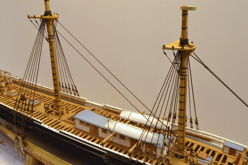
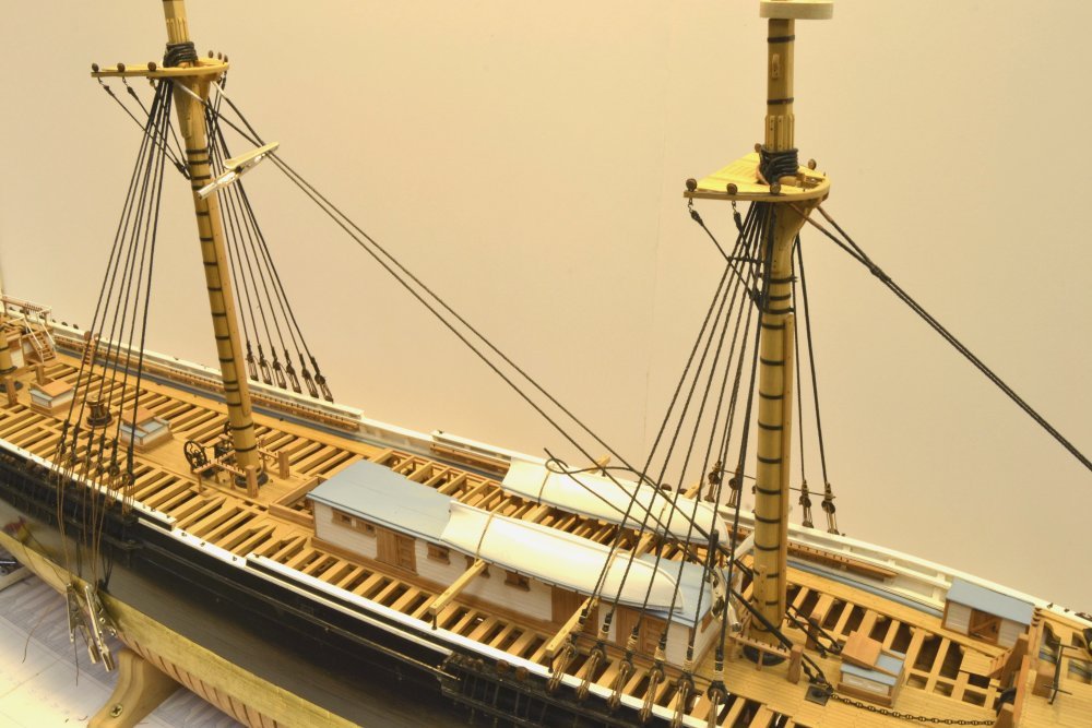
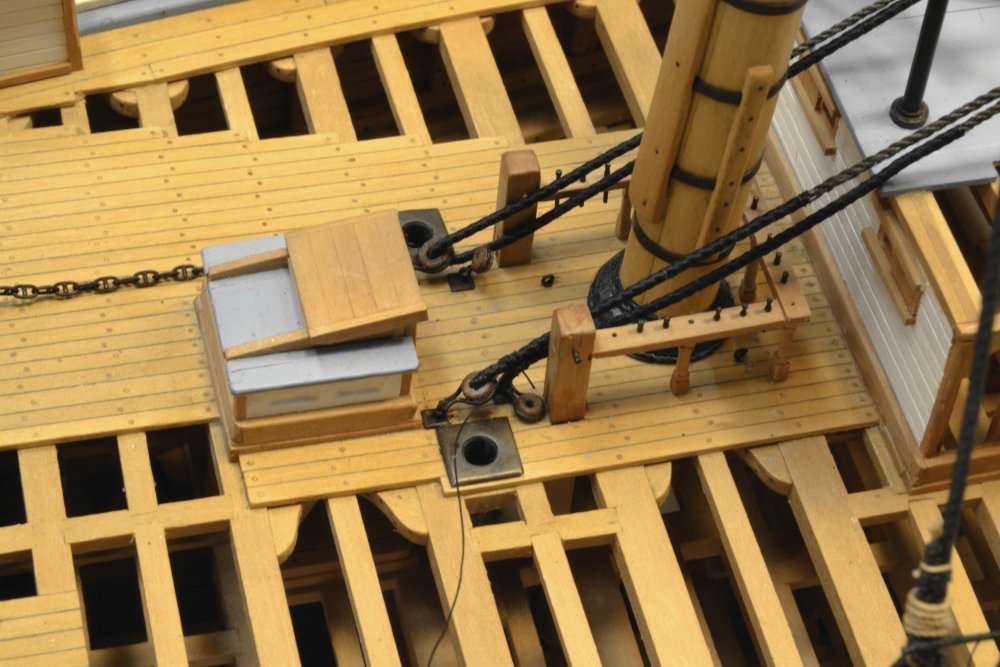
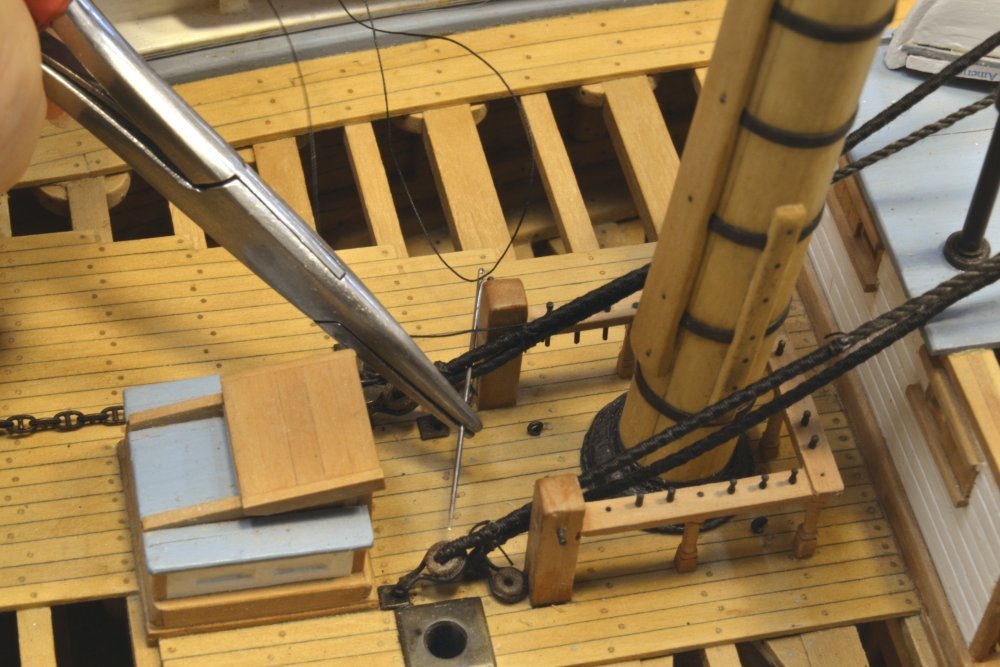
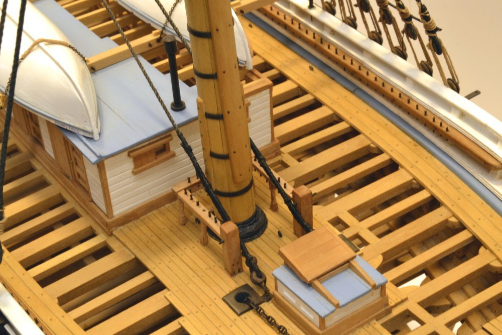
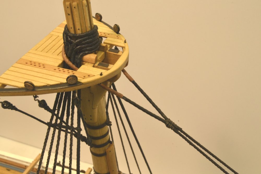
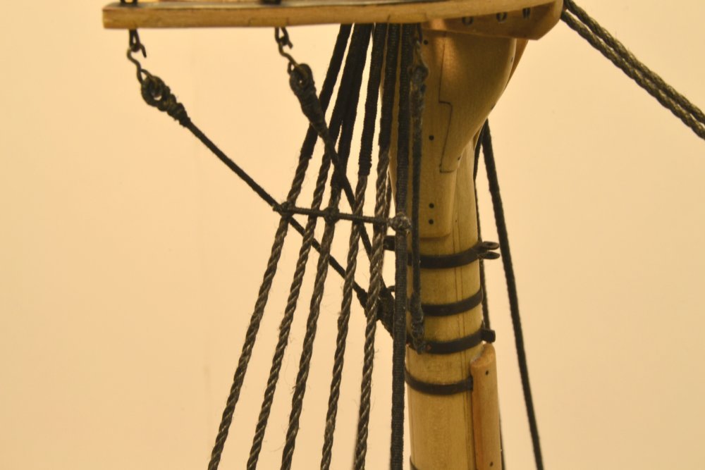
Young America - extreme clipper 1853 Part 210 - Mainstay Once the main shrouds were installed the main stay was next. Like the lower shrouds and the forestay, this was 10 ½" rope. The first picture shows the main shrouds in place and tensioned, and the mainstay rigged so the served areas could be marked out. The shackled bullseyes and eyebolts through the main deck beams were installed earlier. In the next picture the stay has been served and leathered and is rigged to allow the glue on the leathering to dry in position before painting. The stay is clamped where a collar seizing will be placed after the stay is secured at the fore ends. In the next picture the first seizing at the lower port end has been tied. The lower ends of the stay are served as well as the collar at the top. In the next picture frapping turns to the first seizing on the port side are being made with the aid of a sewing needle. The next picture shows the four seizings on each leg completed. I was very pleased that the stay clears the chafing battens on the mast by about six inches and is just inside the sheet bitts, so I may not install the spreader that was used if needed to keep the stays outside the mast. The smaller bullseyes inside and just aft of those for the main stay will anchor the main topmast stay and will hopefully fit as well as the first. The last picture shows the completed main stay with the collar seizing applied below the top. The sheer poles have yet to be installed on the main shrouds and the lanyards are still dangling loose. Ed
- 3,618 replies
-
- 49
-
-
- young america
- clipper
- (and 1 more)
-
Brig Eagle by robnbill - 1:48
EdT replied to robnbill's topic in - Build logs for subjects built 1801 - 1850
Lovely work, Bill. Just catching up with your latest and some of your earlier posts. The belaying pins look great. Ed -
We've been missing your beautiful work, Bruce. Great to see you back. Ed
-
Rest easy, Druxey. The leathering was made with tissue - like the parcelling - then painted. Very easy to do. Ed
- 3,618 replies
-
- 5
-
-
- young america
- clipper
- (and 1 more)
-
Yes, I know what you mean, Greg. My initial reaction to the seemingly small sizes of iron straps etc. was similar - and I'm kind of a nut on strength issues. Some research and some arithmetic helped. Based on some numbers in S.B. Luce, Seamanship, 1868, an 11" hemp rope of the time had a breaking strain of 64,000 lbs. On rope of this size on the model I am using 24 gauge copper wire for straps and bolts. At .020" diameter this converts to just less than 1 1/2" at 1:72. If my math is right (always questionable) iron rod of this diameter would have a tensile strength of about 90,000 lbs (55 KPSI), about 1.5 times the strength of the rope itself. So, not to worry. I would assume the rope around the deadeye/bullseye would beak first. I took the bolts through the knightheads (assume nuts), rather than into the tops as is shown on some drawings, because I thought bolting into the end grain would subject the knightheads to splitting. I wasn't too crazy about main stay eyebolts in foremast bitts, but this was common. Wait till we get to wire rigging sizes. Ed
- 3,618 replies
-
- 7
-
-
- young america
- clipper
- (and 1 more)
-
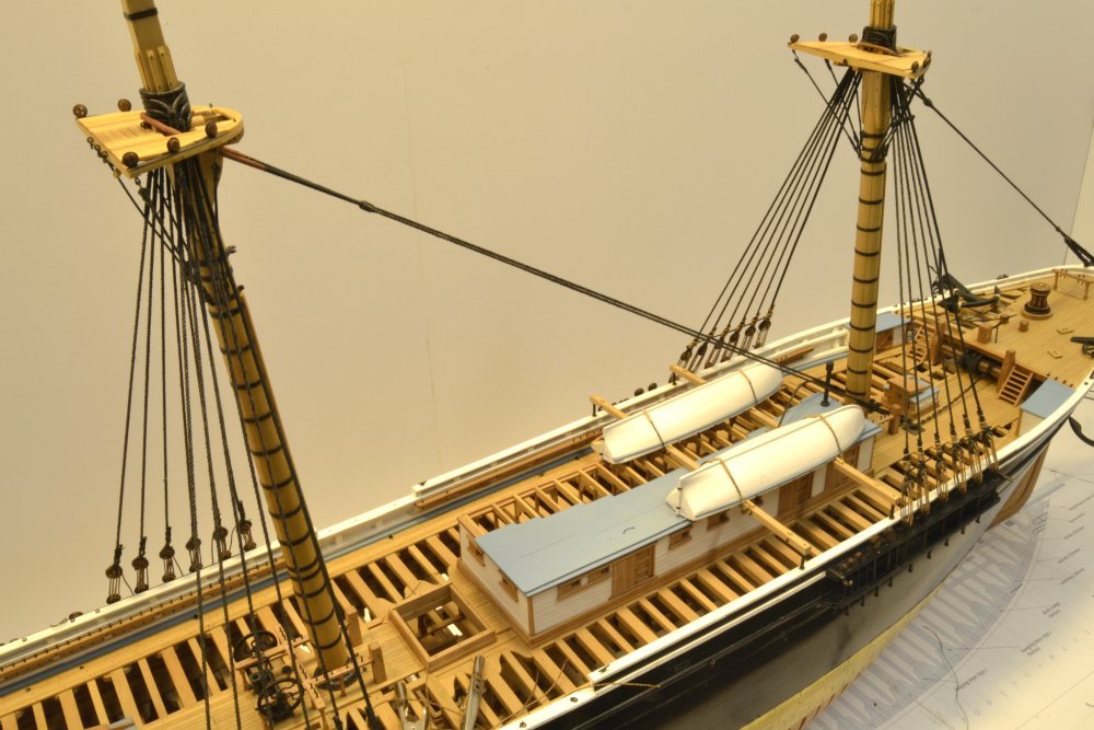
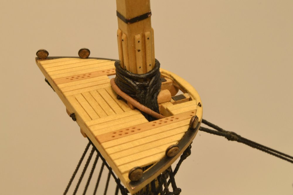
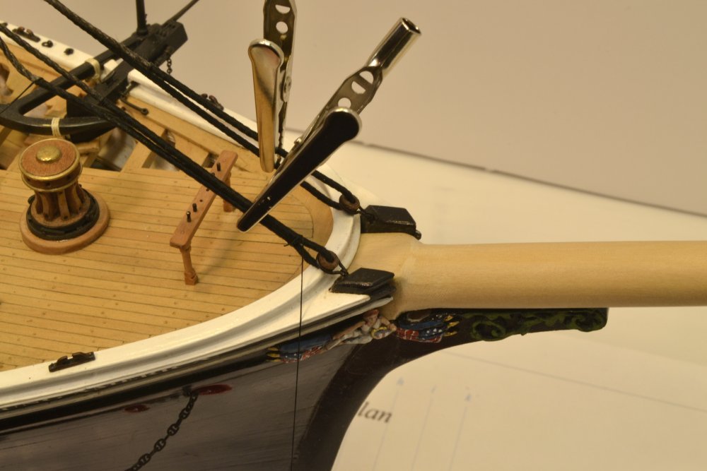
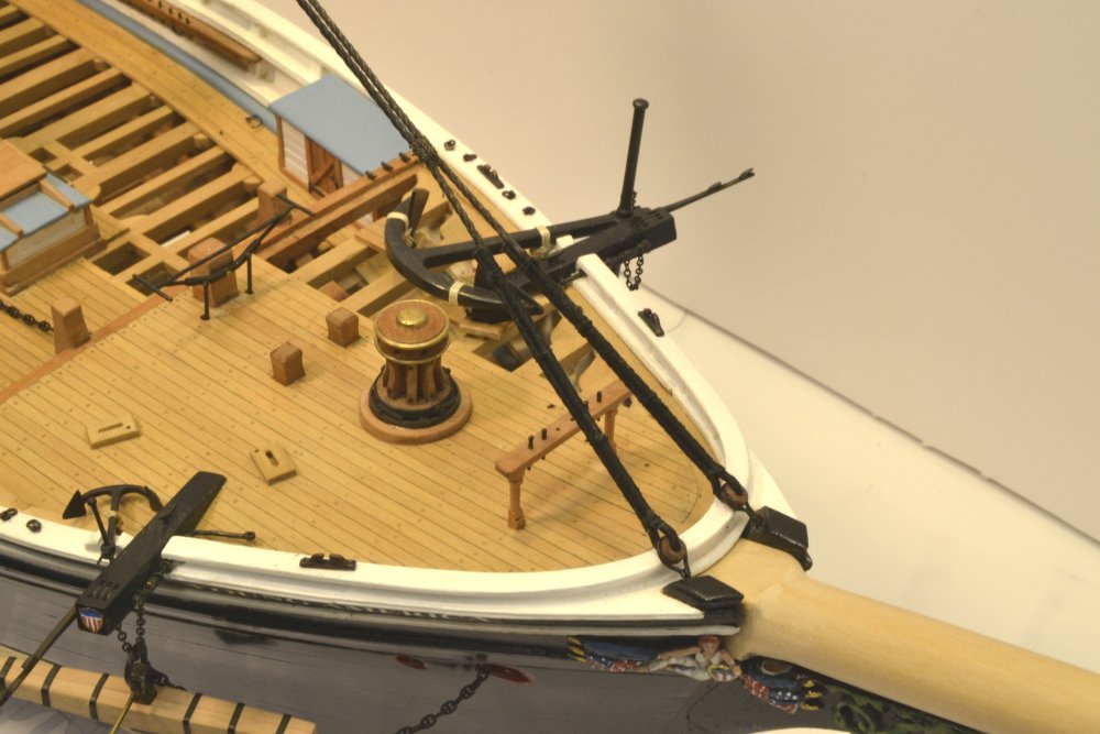
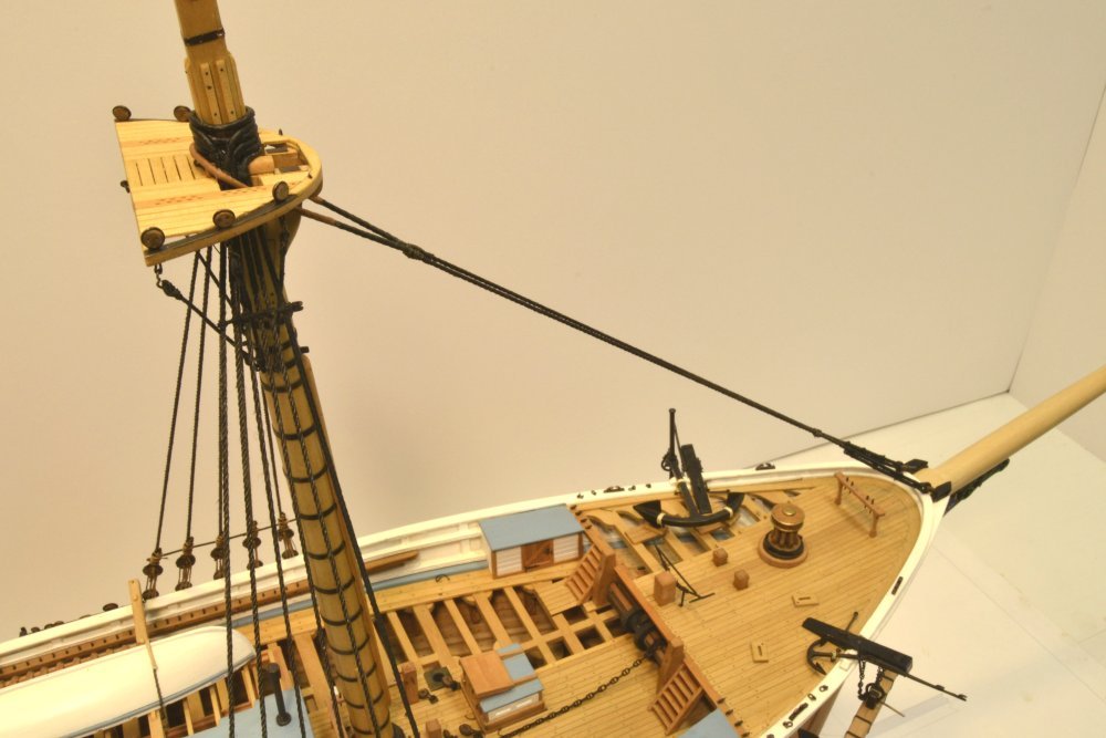
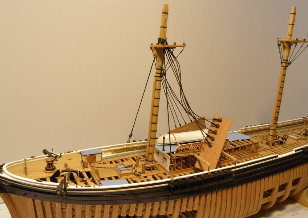
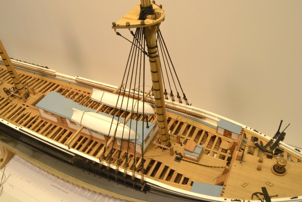
Young America - extreme clipper 1853 Part 209 Forestay The forestay was a fairly simple job to install, but before getting into it, I should say a few words about my sequence. I am sure there are many approaches to this, but my general plan is to work fore to aft, bottom up, so I will do the standing rigging on the lower masts, working aft, then either go on to the lower yards or topmasts – not decided yet. Details on the lower shrouds like fairleads, staves and ratlines will be added later when convenient. The first picture shows the installed forestay. It is 10½" rope (like the lower shrouds), doubled around the masthead with a seized collar, secured with four seizings on each leg to bullseyes with iron straps shackled to eyebolts in the knightheads. These were installed earlier. The lower legs are seized together above the lower seizings. The rope is served around the collar and at the lower ends and the upper part around the masthead is leathered. The next picture shows the leathered collar bedded on the shrouds. The next picture shows the extent of the upper serving and leathering and the upper seizing. In the next picture the lower ends of the stay have been hauled up and clipped so the seizings can be put on. The starboard seizing has been started in the picture. The next picture shows the lower legs completed and the lower seizing installed to pull them together. Finally, the completed stay from above. There is quite a bit of work to do on the bowsprit, but because the forestay is secured at the knightheads, I can defer this until the fore topmast is being fitted. Next, the main and mizzen lower mast rigging, but first I want to replace all those topmast backstay chains and channel deadeyes discussed in an earlier post. Ed
- 3,618 replies
-
- 31
-
-
- young america
- clipper
- (and 1 more)
-
I love your precise work, Johann. Beautiful. Ed
-
Thank you, Scott. I appreciate your comments very much. They are right on point as far as the recent discussion is concerned. I agree that there are choices to be made and that there probably was no one way of doing things. Ed
- 3,618 replies
-
- 3
-
-
- young america
- clipper
- (and 1 more)
-
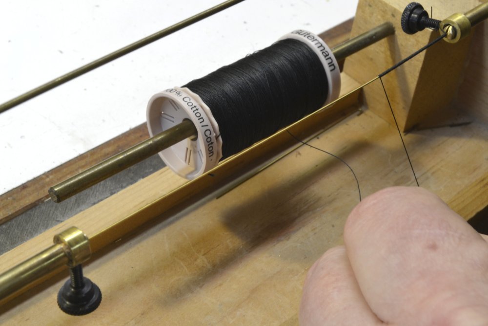
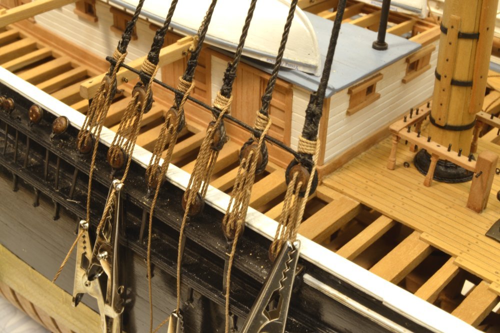
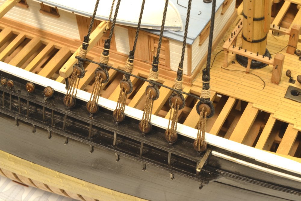
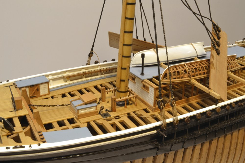
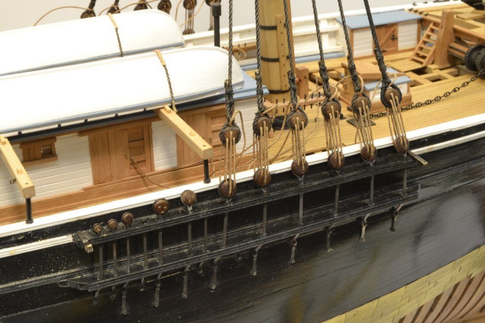
Young America - extreme clipper 1853 Part 208 – Sheer Poles Ok, lets get off the tar-baby. Sheer poles were 1" diameter rods that were lashed across the shrouds just above the deadeyes and just below the futtock shrouds. The purpose was to spread the shrouds evenly, to help keep them in a flat plane and to prevent twisting. They apparently came into use around the end of the 18th century. They were assisted by wood staves lashed at intervals between the sheer poles and groups of ratlines. The staves will be installed much later, with the ratlines, but the sheer poles are needed now. The first picture shows a small diameter brass rod being served for use as a sheer pole. The next picture shows this served rod spread across and lashed to the fore lower starboard shrouds just above the deadeyes. The rod will later be cut to length after touching the ends with a drop of CA to seal the serving to the rod. Except for the first shroud, the lanyards are kept down, out of the way. After final tension adjustment, the lanyards were brought up through the space above the deadeye and wrapped four turns around the shrouds, as seen in the next picture. The four turns is arbitrary. The lanyards were normally wrapped around until used up and were generally much less tidy than I tried to make these. In the next picture the lanyards are finished off. One additional turn was taken and a clove hitch on knotted the back sides. A length of remaining lanyard was then secured to the inside of the shrouds with a small rope lashing. The small sheer pole under the futtock shrouds is shown in the last picture. Only three of the six lashings have been tied in the picture. Note that there is no connection between the shrouds and futtock shrouds that pass between them. This is different from earlier man-of-war practice. The forestay may be seen in the top upper right corner of the photo. It is the next item to be installed once the sheer poles are finished on each side. Ed
- 3,618 replies
-
- 30
-
-
- young america
- clipper
- (and 1 more)
-
Okay, everyone. Thanks for the input, but I guess its time to move on and I will try to make that transition with a new post today, if possible. Thank you, Druxey, for your perspective on what I guess is "one of those" topics. For what its worth, I share your view on this and am modeling accordingly. In cases like this everyone needs to satisfy their own perspective. I suggest if there is interest in continuing this discussion, that someone start a topic. Thanks again. Ed
- 3,618 replies
-
- 3
-
-
- young america
- clipper
- (and 1 more)
-
Thanks for your comments, Jerry, and thanks for posting the diagram. I am familiar with it. I do have remaining questions about the use of tar. Perhaps you could comment further on that. My understanding is as follows: Pine tar (aka Stockholm Tar, aka tar) is a viscous liquid obtained by decomposing pine wood under heat and pressure. The term Stockholm Tar derives from the virtual monopoly held on this product by Sweden during the 17th, 18th, 19th(?) centuries. I suspect American ships sourced this from our own lush pine forests. The material is a fairly viscous, sticky dark brown, fluid, slightly soluble in water. All rope used in ship rigging was tarred as part of the rope making process, by dragging the hemp yarns through a trough of tar at or near its boiling point. It would be a lot less viscous at this temperature and would penetrate the hemp strands. The description of the process appears in Luce, Seamanship, 1868 p49. He states that the absorption was 25%, which I take to mean the amount of increase in the rope's weight. At any rate, all rope had a fairly high content of tar, whether standing or running. Later, Luce discusses protection of standing rigging (p. 58) as follows: "Standing rigging is protected from the weather by covering it with a coating of blacking made of tar, whiskey, lampblack, litharge, and salt water." I found this interesting for a couple reasons. First, because a small amount of carbon black goes a long way, so the addition of it in the form of lamp black would certainly make standing rigging black – as opposed to the deep brown of tar alone. Second is the use of litharge (lead oxide) in the recipe. He doesn't say how much, but the purpose of this would be a thickener, like the lead in lead-based paints. After "painting" this on standing rigging, and after evaporation of the water and "whiskey" I would expect this to harden into a tough rubbery layer. So, my conclusion, based on Luce, perhaps incorrect, is that there are differences in what we think of as "tarring" of rigging. We are then left to decide on how to represent this on models. So, am I off base in thinking that lanyards might receive a different treatment than say, shrouds or stays? I'd be genuinely interested in any further light you, or others, could shed on this. Thanks, Ed
- 3,618 replies
-
- 4
-
-
- young america
- clipper
- (and 1 more)
-
Tony, I am sorry for the confusion over the plans. The drawings were all planned and numbered early on, before the books. The inclusion of Drawing 13 in Volume I has caused some confusion. The short answer is that there is no 2A. The 2B was meant to identify this plan as the Base, or shipway drawing. It does sound like Seawatch owes you a drawing 4, so I am sure Bob will send you one. Let me know if this does not happen. I have attached a list of the large printed drawings for your reference. I posted this in an Addendum on this forum topic some time ago. I suggest that you go back through this topic, download and print all the Addenda. While most of these deal with minor corrections and clarifications, there is also other useful supplementary information. There are 6 addenda for Volume I and 1 for Volume 2, all as printable pdfs. Naiad Frigate Drawing Lists[1].pdf Thank you for your interest in the books. I hope you will decide to proceed with the project. Ed
-
Well here goes, Frank. Not sure I understood the first question correctly, but maybe this will help. How should the stern timbers be drawn? Since they are diagonal, the length shown in the top view does not represent the actual length of the timbers. I assume the question is how to loft the true shape of the stern timbers. Since the stern timbers are in vertical planes parallel to the keel, their true shape will be shown in the side elevation view. However, only the center timbers are shown on the sectional, elevation view. The timbers on either side will be shorter. At the forward end, the timbers all terminate at the strongback that is perpendicular to the keel so the forward ends of the timbers are defined (and are the same) on the existing elevation view. To determine the length of each timber project its aft end from the plan view down (or up) to the elevation view. If you wish to loft the bevels you will need to project both the inboard and outboard faces of the timber down to the elevation view. If you plan to bevel the timbers after installing (recommended in this case), use the inboard, larger face of the timber when projecting the end from the plan to the elevation view. Assuming the upward curve of the transom is constant, join the lower point of the timber at the strongback to the end of the timber with a curve of that shape. Draw in the top line of the timber using the molded dimensions of the center timbers. If you are not sure about the shape of the upward curve, leave material for later beveling by eye. 2. Should the outer edge of the stern timbers be shaped to follow the slight curve of the transom? I would say yes, but perhaps by eye after assembly as recommended above. 3. How are the outermost stern timbers secured in place? They seem to be floating in space in the photos, perhaps because rot was cut off? I would be inclined to found them to the strongback, which is a sort of wing transom. These may need to be thicker than the other timbers so the can be shaped to the outer hull. 4. Should the diagonal bracing be installed by notching the stern timbers to accommodate them, or should they lay on the stern timbers? In the photos they appear to be using short cuts of wood between the timbers that a fastened to "shelf" pieces screwed to the timbers. I believe notching the timbers to take the diagonals would be stronger. 5. Would it make sense to install the aft deck beams before the stern timbers? This might give a ‘landing place’ for the outer stern timbers, but it would also require the deck clamp to be installed first. I have no opinion on this, but would probably want the structure to be self-supporting first. Cheers, Ed
- 878 replies
-
- 10
-
-
Rob, I cannot comment on the historical authenticity of the restoration work on Constitution, nor can I corroborate your theory on twisting shrouds. That issue has not come up in any references that I have, but... Later edit: I found a reference to shroud twisting in James Lees Masting, and Rigging... He does not cite the cause but says that sheer poles were intoduced in the 1800's to prevent shroud twisting.
- 3,618 replies
-
- 4
-
-
- young america
- clipper
- (and 1 more)
-
A very interesting question, Scott. In preparing to rig the model, I have vacillated back and forth on this and I will confess that I do not know the correct answer on how this was done - if there is one. As with many things, practices may have been local. After much consideration I decided, perhaps incorrectly, to cross the short end to the left, over the standing end of the shroud - when viewed from outside channel. I am quite convinced that crossing the short end to the left is correct for right-hand laid shrouds that seem to have been universally used on american ships. But under or over? That is the question. So, what were my sources telling me? First, Darcy Lever, Young Officer's Sheet Anchor, 1819 - a primary source on seamanship/practice: specifically states that the end is taken over the standing part. The two diagrams show the standing part to the right and right/handed rope. Because so many sources parrot Lever, or other Lever derivatives, I give this description high regard. I am aware of the Thomas Hornsby detail on the Crothers drawing that you refer to that shows the short leg behind the standing part. Kipping, 1864 London says, "the end of the shroud is taken underneath round the deadeye, inside standing, or masthead part." No mention of right or left, but from other parts of the text I surmise the use of shroud-laid, ie left-handed rope. S.B. Luce, Seamanship, 1868, New York, in his throat seizing diagram, shows the short leg taken over the standing leg to the left with right-handed rope - exactly like Lever. However, in his description of turning in deadeyes he repeats Kipping word for word, indicating the opposite. However, he says, "The principal caution is to keep the lay in the rope, as it prevents wet getting in." He then goes on to quote Boyd's Naval Cadet Manual, which discusses the specific point (under/over) as this relates to the lay of the rope, describing the tendency of the rope to naturally loop over the standing end if it is twisted to tighten the lay. He then admits this is reasonable, but goes on to say " it is diametrically opposite to the method practiced by our seamen." That is to say, taken under the standing leg without any twisting. He calls this "with the sun" but it seems to me both are with the sun, but one is over and the other under. Am I confused or is Luce confused? His two diagrams on deadeyes are ambiguous on the point. Remember, Scott, you asked this question. So, based on all the above, I took a short length of right-handed rope and twisted the left hand end. If the lay is tightened, the left hand, short part, naturally loops over the standing end. If the lays is loosened by the twist in the opposite direction the short end goes behind the standing leg. Try it. The opposite would of course be true for left-handed, shroud laid rope. Based on all this, I decided to loop the short legs over to keep the lay of the rope tight, but I could easily be convinced that the opposite was done. So, I would say: Toss up. Great question. Thanks, Ed Later edit: substitute cable-laid for shroud laid in above text.
- 3,618 replies
-
- 7
-
-
- young america
- clipper
- (and 1 more)
-
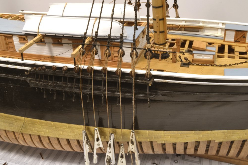
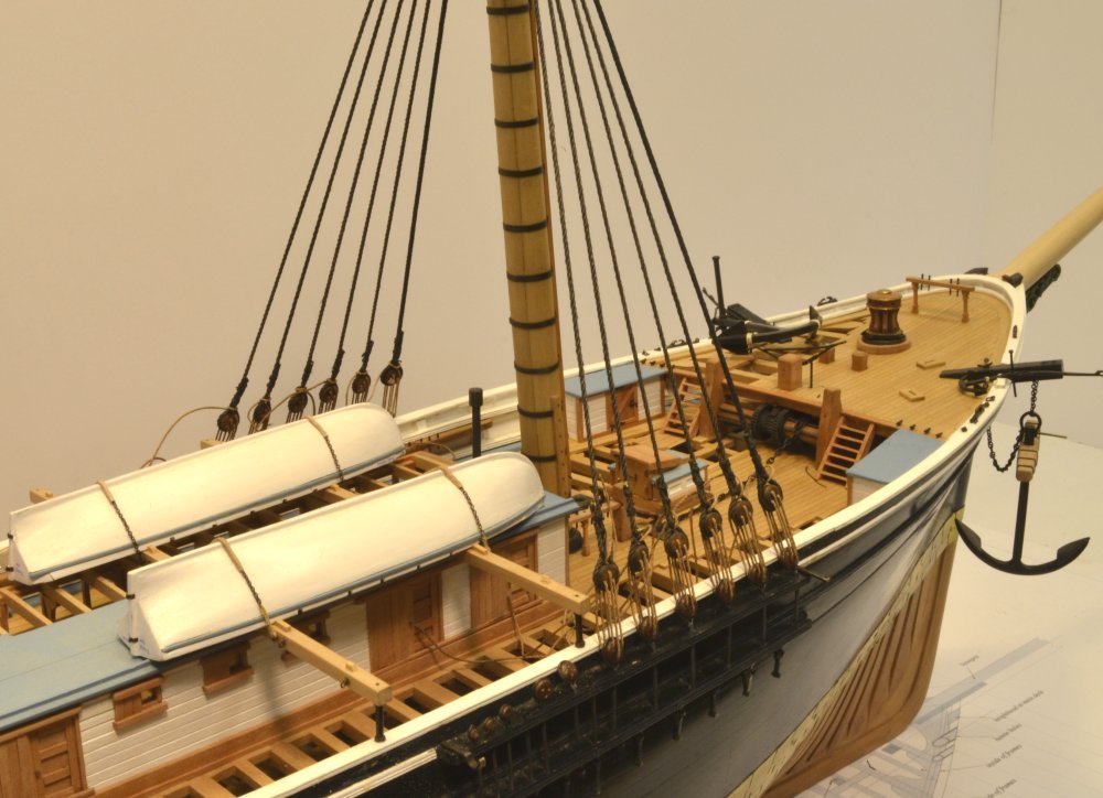
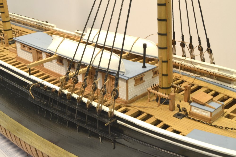
Young America - extreme clipper 1853 Part 207 – Reeving Deadeyes The first picture shows deadeyes reeved on the two forward shrouds. The other shrouds are left attached to the fixtures to avoid them getting out of order. In the next picture the second shroud has been reeved on the port side. Keen observers will note that the stop knot on the #1 starboard side is on the right side of the deadeye – viewed from the deck. Alas, while this would be correct for left-handed shrouds, it is incorrect for my right-handed shrouds – a mistake I discovered only after reeving 10 shrouds. In the next picture, those 10 have been redone and the two remaining shrouds completed – a few hours of avoidable rework. The lanyards have been hauled up to tension the shrouds. I stretched all this rope after laying it up. Linen has very little stretch to it after this, so the deadeyes line up well after tensioning, as was the case in practice. In practice, lanyards were hauled up using a tackle that was secured to the shroud some distance above the deadeye. In earlier ships and perhaps in Naval ships of the time (?), tackles were hooked to burton pendants that went over the masthead before the shrouds. Hence there are no burtons on the YA model. The excess lanyard that is strewn about the deck will be trimmed off after it is wrapped around the shrouds and made fast. This will be done after lashing on the iron sheer poles. The next picture is a closer view My dust problem is quite evident in this picture, but it would be premature to clean up at this stage, because I will make more dust when I replace the next two deadeyes and their chains to handle the larger topmast backstays. This change was mentioned in an earlier post. Finally, a view from above. Next step is making and installing the iron sheer poles across the tops of the deadeyes and then winding up the lanyard excess. Ed
- 3,618 replies
-
- 31
-
-
- young america
- clipper
- (and 1 more)
-
Hi Nils, and thanks for your comment. Your question may be answered in the next post, which I may get out today, but you will see that for "reeving" the deadeye lanyards, the lines are removed from the fixture. The fixture only sets the length of the shrouds to the deadeyes, as was done in rigging the real ships by measurements from the actual masts or from drafts. This was done after stretching. The shrouds were then served, doubled, the collar seizings put on, and the shrouds cut to length, allowing for increased length going aft. The lower ends were sometimes served as well. Deadeyes were then turned in and the shrouds placed over the masthead. The use of the fixture I described replaces only this part of the process. Once the deaeyes are turned in, they are reeved individually and the shrouds are tensioned using the lanyards, once initially and again when the full gang is reeved. This leaves them all at a pretty uniform height, as may be seen in photos of YA and other ships. The iron sheer poles were then added and the excess lanyard wound around the shrouds and made fast. This will be described in Part 207 shortly. I may also add that I am using several sources of information on this, mainly documentation from the period on seamanship, mastmaking and rigging - both American and British. These differ in some details but are otherwise pretty consistent - sometimes even word for word. The differences lead me to believe that while practices were similar, there was variation, so I have used judgement on some things. Ed
- 3,618 replies
-
- 5
-
-
- young america
- clipper
- (and 1 more)
-
Thanks, everyone. Bill, I don't want to deceive anyone on the parcelling. I only parcelled over the serving around the masthead, not under any serving. This does leave some profile of the rope strands through the serving, but parcelling - or worming and parcelling - under the serving would add too much diameter to the model rope. The thread I am using is about 1" diameter at 1:72, thicker than full size serving, but not too far off considering that full size rope is wormed and parcelled first. The lower shrouds on the model are 10 1/2" rope (3 1/2" diameter) - the largest lines on the ship. The actual unserved diameter is a little less than .045". Larger rope would show more of the effect you describe and at larger scales. like 1:48 or larger, might benefit from worming and/or parcelling before serving - but this would be limited to a few very large lines. For example, Victory's mainstay was 19" rope (6" diameter). Ed
- 3,618 replies
-
- 5
-
-
- young america
- clipper
- (and 1 more)
-
Thanks for the comments, guys. I won't take too much credit for the deadeye jig. The idea came from Longridge Anatomy (p. 229) when I was rigging Victory 10+ years ago. I used wire vs. his pins. Here's a link to that part of the Victory build log. https://modelshipworld.com/index.php?/topic/316-hms-victory-by-edt-196-pob/&page=2 Ed
- 3,618 replies
-
- 7
-
-
- young america
- clipper
- (and 1 more)