EdT
-
Posts
2,214 -
Joined
-
Last visited
Content Type
Profiles
Forums
Gallery
Events
Everything posted by EdT
-
Wonderful work, Nils. The scope and detail of this project amazes me. Ed
- 2,625 replies
-
- 5
-

-
- kaiser wilhelm der grosse
- passenger steamer
- (and 1 more)
-
Thank you, everyone for the comments, questions and likes. I will try to answer the questions. Marc, the first question is: eyebolts or lugs? - lugs being tabs with a hole drilled. I have seen both in contemporary documents, so I decided to go with eyebolts. There are very many of these to be made, at the yard arms, at the quarters, etc. so soldering on drilled lugs would be a major chore. Soldering eyebolts on these thin (.010" to .015") bands would be as arduous as soldering lugs. The method I used for these was to install the band, then drill through it to insert eyebolts into the wood. These are held with CA. The eyebolts do not then depend on the strength of the thin bands but provide a solid anchor for both the rigging and the bands themselves. The topmast shrouds will put some strain on these bolts. Also, some eyebolts will have shackles, so by the method I'm using, these soldered assemblies may be inserted later, sometimes perhaps with the lines spliced on. In the case of the futtock bands, the futtocks will be spliced to these later and then siezed to the iron deadeye strops at the rim of the tops. Silver solder, of course. I use a low silver,copper-phosphorus solder-paste (1325 deg F) combination that blackens well with liver of sulfur solution. These parts have very little mass and I have had little trouble adding pieces to the original ring. John, the ends of the bands are butted, not overlapped. I try to bend the ends to touch and stay in contact without other support then add a small blob of solder from the syringe, then touch with the flame and quench in white vinegar. Very quick, very easy. The rings get tested for strength when I push them on to the mandrel for filing, and polishing. Frank, the bands are spaced at around 36", which I believe was the standard for made masts. I will probably space the mizzen bands further apart. Sometimes rework is unavoidable, especially, as you say, if you want to optimize the process. I was disappointed at the traces of black smudging on the first main mast. I never had this problem with LOS on structural work, but that was not subject to handling after blackening. Since the process for making these masts will be described in the usual excruciating detail in Vol III, I wanted to nail down the best process. Its getting there. I always expected metal bands to be a problem. Thanks again, especially for the questions. Ed
- 3,618 replies
-
- 11
-
-
- young america
- clipper
- (and 1 more)
-
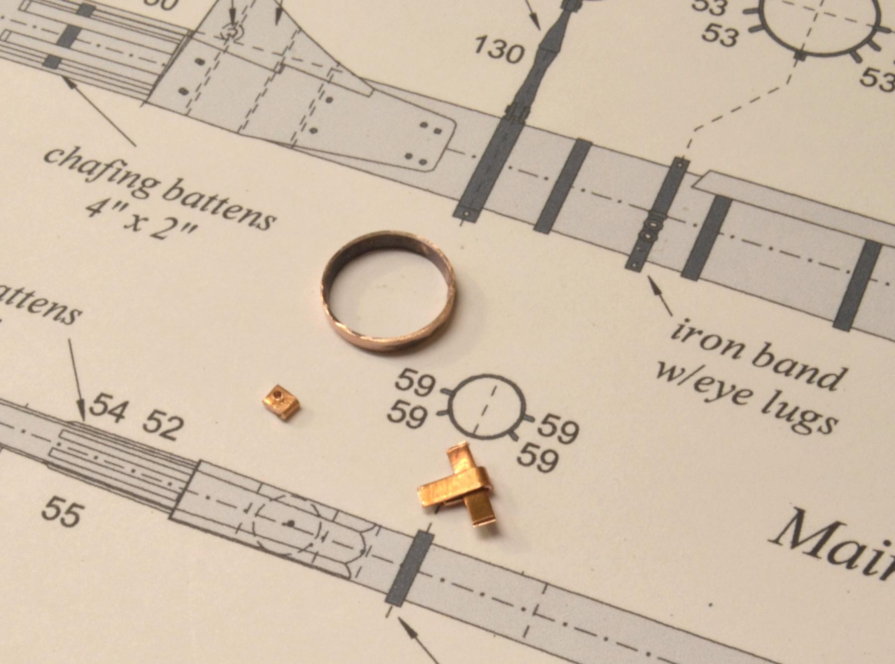
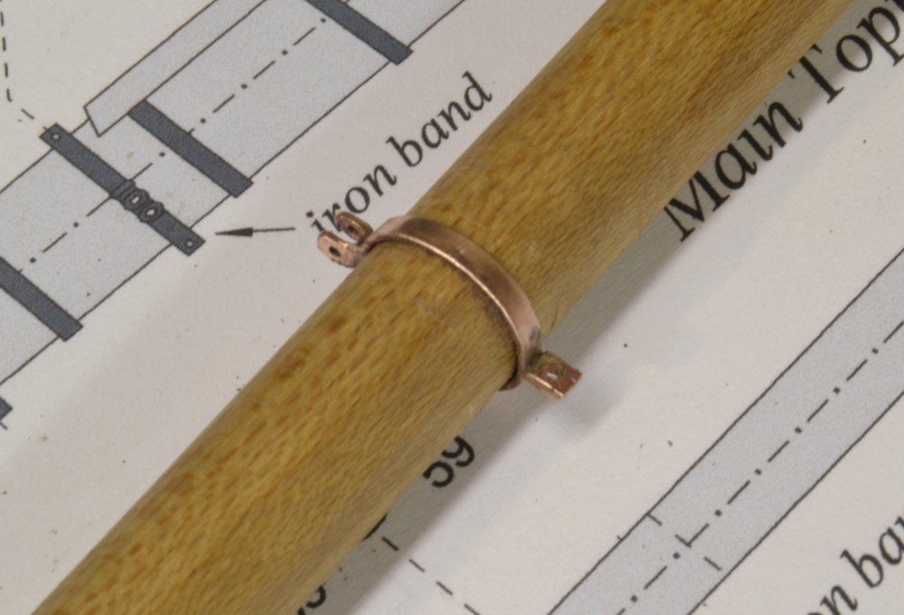
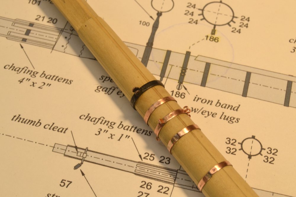
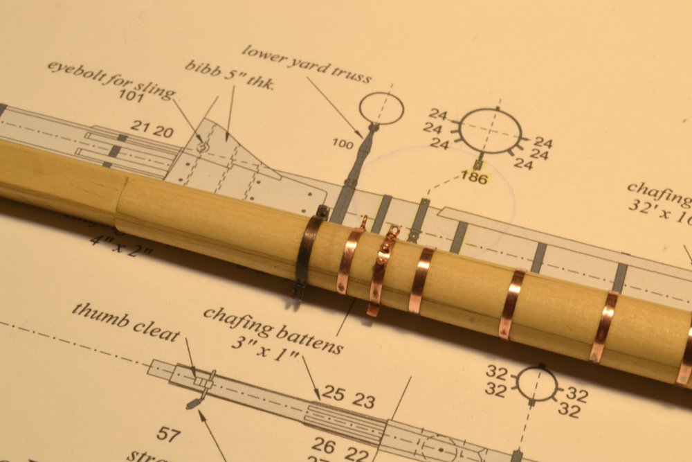
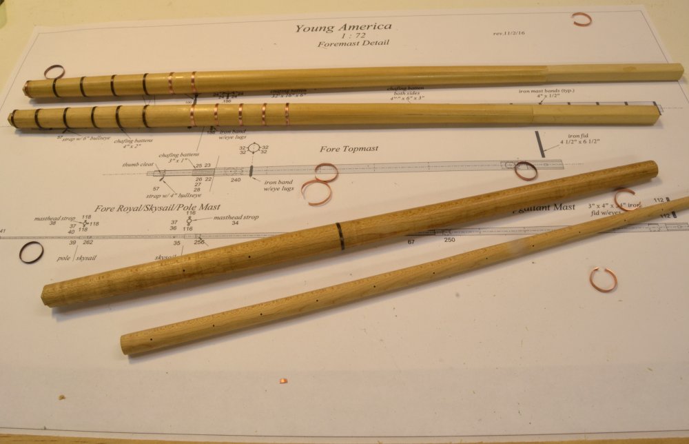
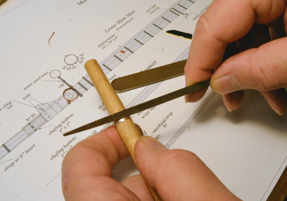
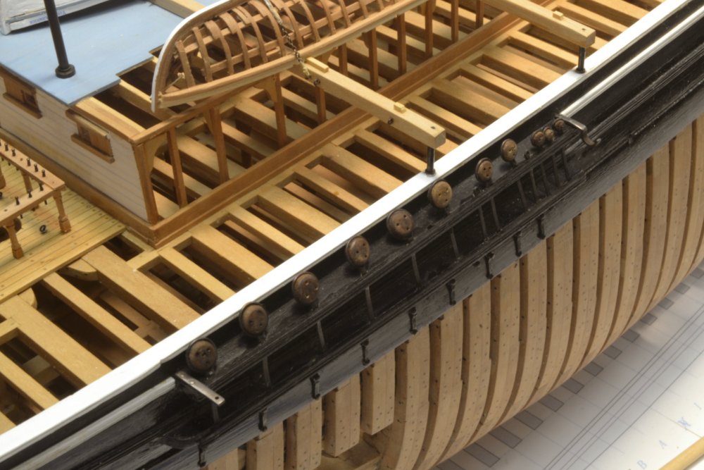
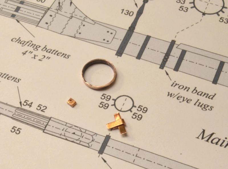
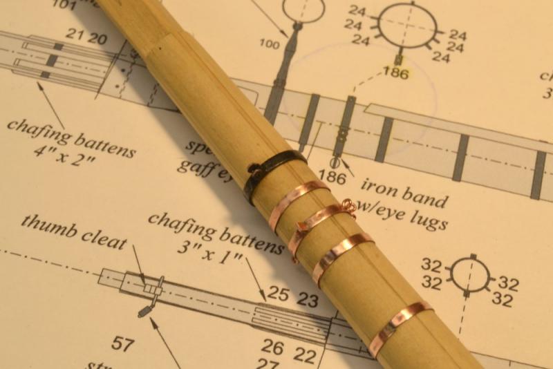
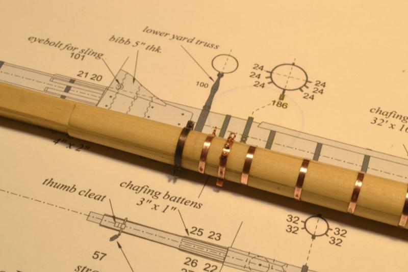
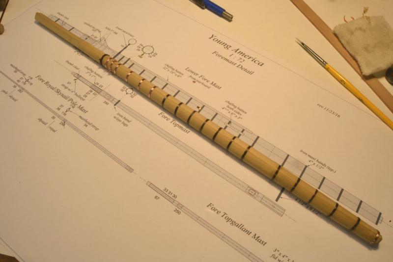
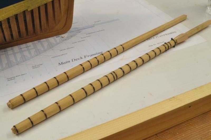
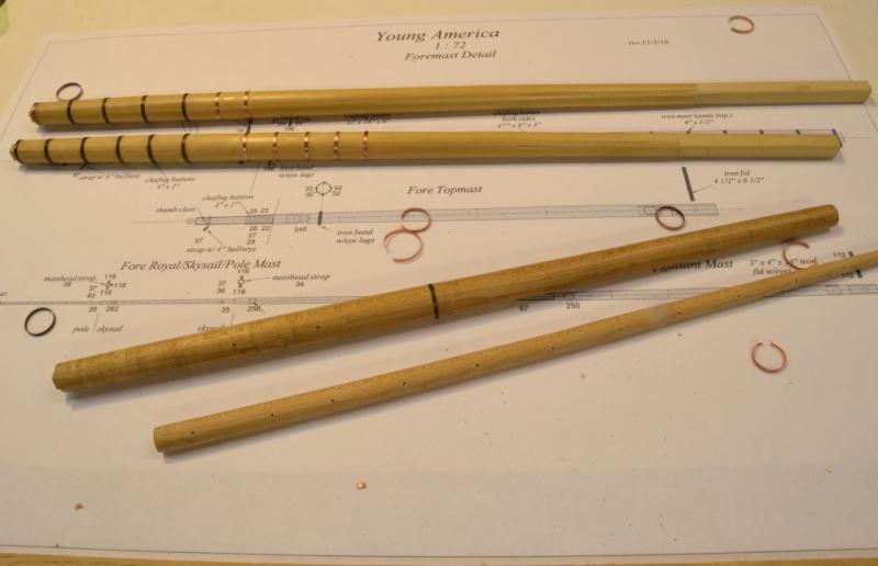
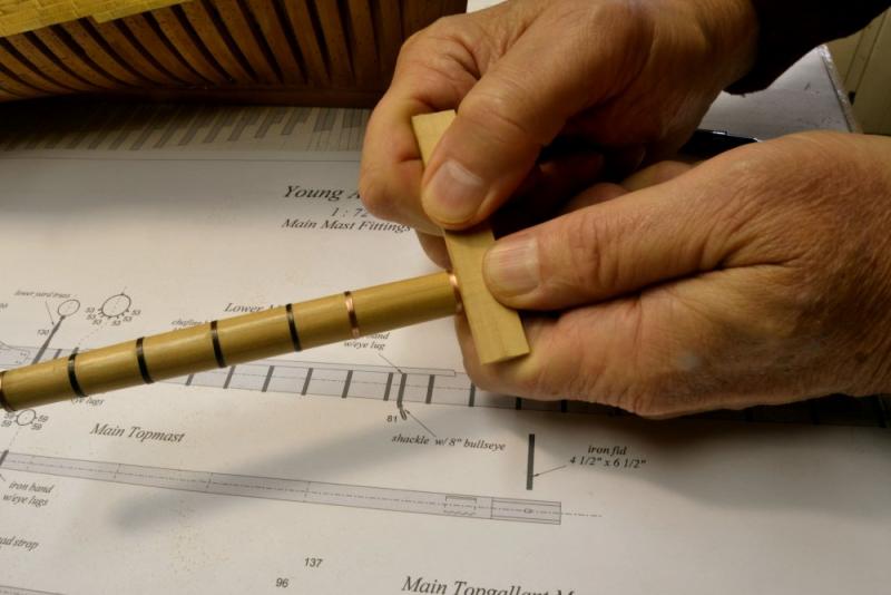
Young America - extreme clipper 1853 Part 185 – Iron Mast Bands 2 In addition to the shrunk-on hoops that reinforced the masts, there were bands for other purposes. On the lower masts these included bands with eyebolts to secure rigging, bands to secure the spencer gaffs and bands that supported the lower yard trusses. These other bands were generally clamped on the mast rather than heat shrunk. I experimented with two different methods for making these. The first picture shows a clamp band bent around the mast ( actually the mandrel) to be soldered in one piece. The next picture shows a band made like the reinforcing bands to which parts will be soldered to form the clamp joint and in this case the bracket for the yard truss. This band is made from thicker material. The tabs on the truss bracket in the lower part of the picture were bent around some band stock to size the gap. The bracket was then hammered square before soldering. In the next picture the truss band has been soldered together and a wire bolt added at the clamp joint. In the picture the band is pushed on to the mandrel for finish filing and polishing. The next picture shows the special bands on the foremast. These are the three at the top. At the top is the truss band – blackened. More on that below. Below that is the band that supports the fore spencer gaff. The eyebolt on the aft side of this is not visible in the picture. Next is the futtock band with six eyebolts for the lower futtocks and one on the aft face to secure a block for another line, I believe one of the main staysail's downhaul. The bands below these are the normal reinforcing bands. The joints that show on these will be covered by the forward chafing batten. The next picture is another view. In this picture the horizontal eye for the spencer gaff is visible in the band below the truss. The pattern of the eyebolts on the futtock band and the chafing batten may be seen in the drawing. The last picture shows the fore mast with all its iron bands installed. Some bands are blackened on this mast and others not. The plan going forward is to defer all blackening until all other work on the mast is complete – hounds, bibbs, battens, cap tenon, yard sling eyebolt, etc. Blackening just before installing the mast will reduce handling of the blackened parts and the resultant rubbing off of the black. It will also help keep the wood surface of the mast clean of black. These were problems on the first main mast. A replacement is in progress. Ed

- 3,618 replies
-
- 38
-
-
- young america
- clipper
- (and 1 more)
-
Micheal. maybe you've tried this but if not, why not mask with tape on either side of the brass flanges, apply liquid masking to the flange, allow to dry, slice the mask along the edge of the tape with a sharp knife to avoid jagged edge, remove the masking tape, paint the funnel, peel off the liquid mask? Ed
- 749 replies
-
- 8
-
-
- albertic
- ocean liner
- (and 2 more)
-
Thank you, Druxey. The process still needs some tinkering - the sequence and the amount of shellac - but I'm pretty happy with it. The main mast in the pictures has been the "laboratory" and will probably be replaced. I think blackening of all the ironwork on the mast will be deferred as the final, final step - done all at once - after the hounds, bibbs, battens, bolts, etc. Just before erecting and wedging. Idea is to minimize handling of the black parts. Rob, I intend to glue and nail the chaffing battens ( there are also two small ones at the sides where the mainstays rub) over the bands using small copper bolts. Even though the solder joint on the bands is barely visible, I am trying to orient them to fall under the forward batten. I am leaving everything above the deck unpainted to show the construction more clearly. This is generally the approach I have been following on structural detail. Painting the hull, cabins and some other trim was the exception. The copper is cut to width using a paper cutter - described in an earlier post - a poor substitute for a brake, but it works. Ed
- 3,618 replies
-
- 10
-
-
- young america
- clipper
- (and 1 more)
-
Thanks, Micheal and Maury for the comments and others for the likes. Maury, the bands were sized to a slightly smaller diameter than at its final position (maybe 1/32" gap). Each band has to be stretched to get to its final position. Inching it along the mast does this. The copper is able to stretch. Care must be taken to keep all sides of the ring straight - the hardest part - and not to push it beyond its spot and overstretch it. Ed
- 3,618 replies
-
- 6
-
-
- young america
- clipper
- (and 1 more)
-
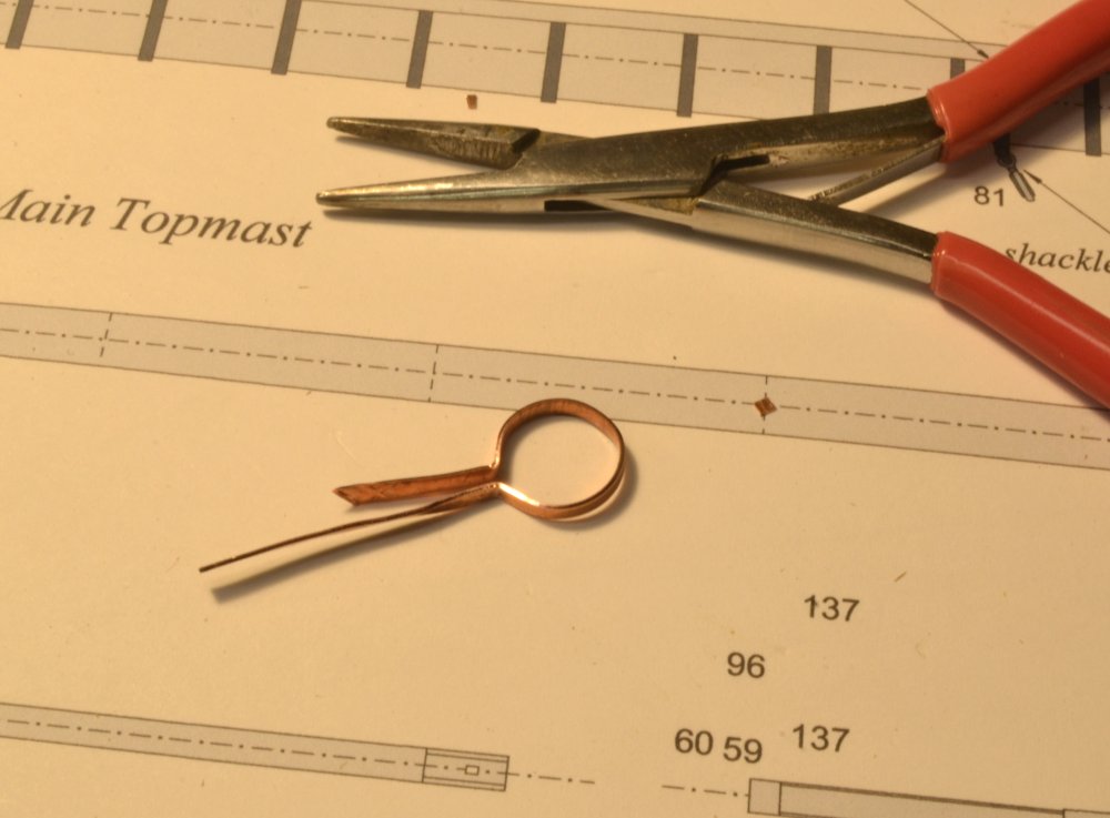
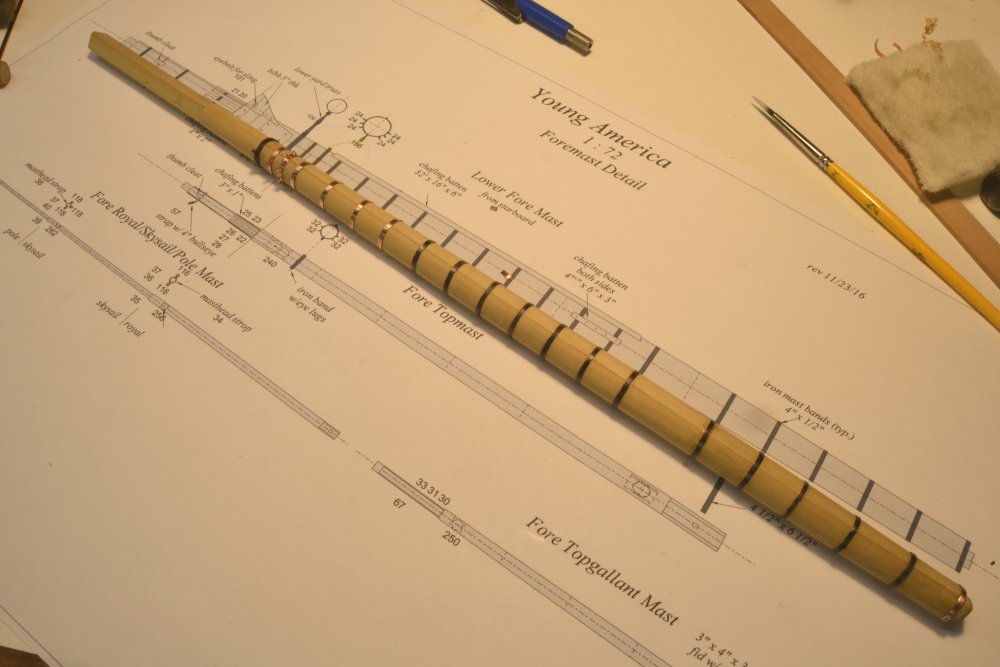
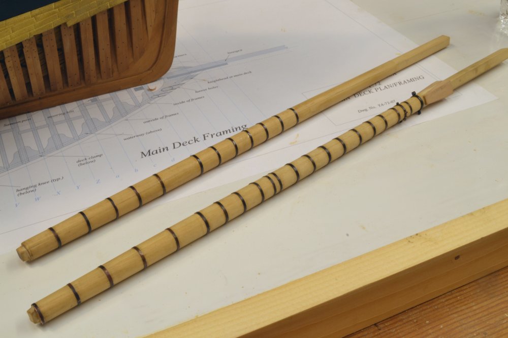
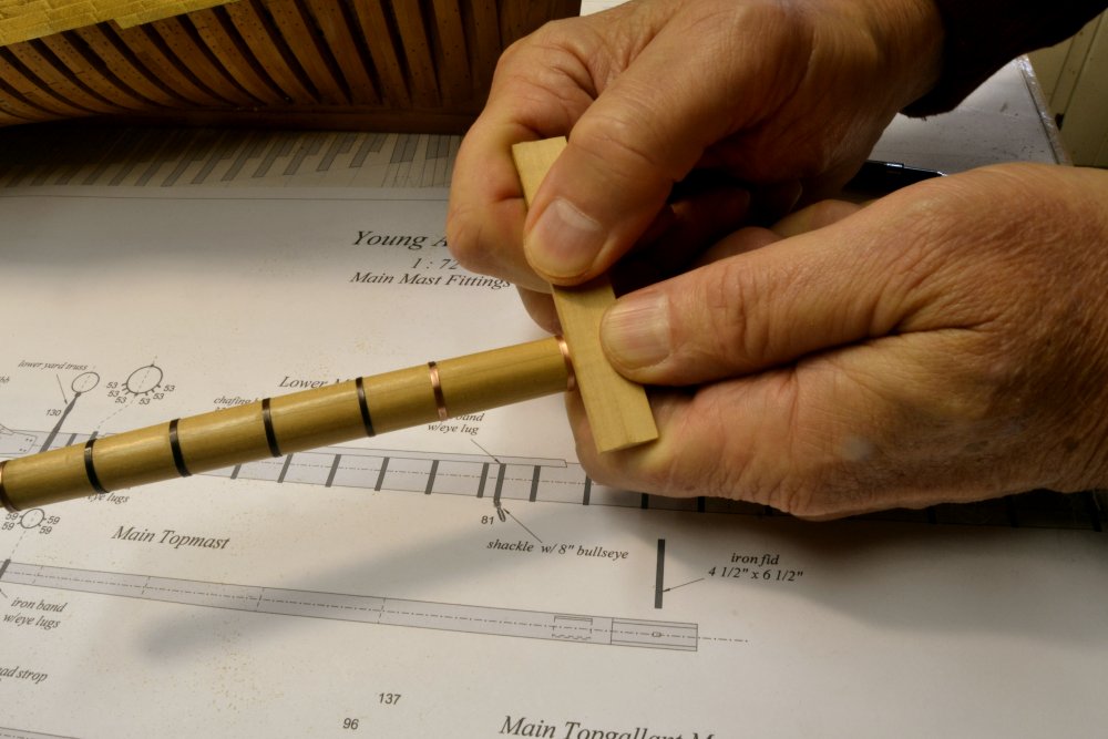
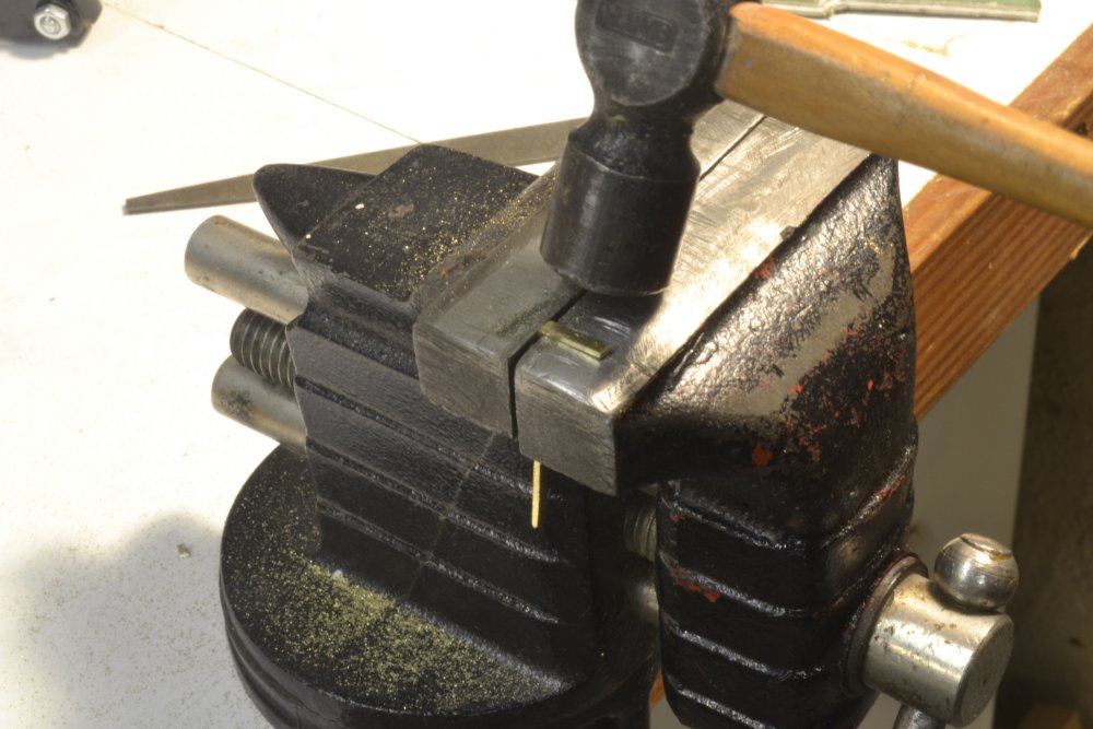
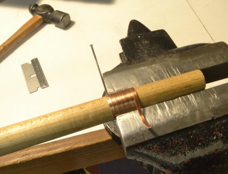
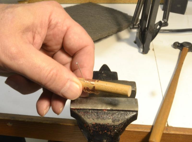
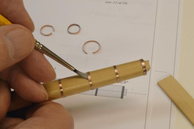
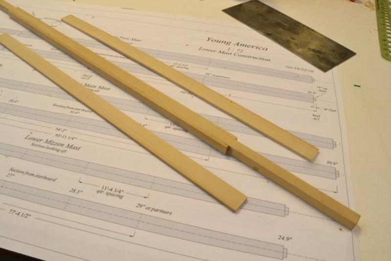
Young America - extreme clipper 1853 Part 184 – Iron Mast Bands Iron hoops, or bands were used to hold made mast sticks together and to reinforce single tree masts. These were 4" wide and ½" thick and were spaced about 36" apart. Circumference of the mast at the band location was measured and a ring of that diameter was forged. To install on the mast the band was heated, slipped on by the smaller end and driven into place. It was then quenched with water to create a tight shrink fit before it had a chance to char the mast. The bands on the model are copper, made from .010" sheet stock sliced into 4" strips. Once the bands are sized and silver-soldered, the main issues become fixing them in position on the mast and blackening them without getting visible black smudges on the mast. The solution (no pun intended) I adopted was shellac – to be explained below. First, a look at the (almost) final product. In the first picture the main mast is fully hooped and the fore mast is in progress. There are a few special bands on the main mast – to be described later. Also, on that mast, with the bands complete, the hounds are being fitted. This cannot be done until the bands above main deck partners are slipped over the top. The housing bands – below the deck – are slipped on from the bottom. When the masts were made, I also shaped two mandrels to aid in making the bands, one the shape of the fore mast and one smaller. These are shown in the next picture with main and fore masts in progress. Except for overall length and housing length, the main and fore masts are virtually identical in their diameters. The mandrels have pin holes drilled along their length for use as shown below. In the picture a strip has been drilled on one end, pinned to the mandrel at the desired diameter, wrapped tightly with the copper strip, and then clamped in the vise. The hammer and razor blade in the picture were used to cut squarely through the strip, yielding open rings as shown below. I won't go through complete detail for sizing the rings, except to say that they were trimmed before soldering to yield a diameter slightly smaller than the diameter of their position on the mast. In the next picture a soldered ring has been fitted over the mandrel for filing and polishing. In the next picture a ring is being pushed into its position in small, even steps using a piece of hard wood. By the time it gets to where it belongs it will have been stretched and will be fairly tight on the mast. Before banding, the mast was given a coating of thinned, clear shellac for two reasons: 1) the shellac will act as a sealer and prevent excess blackening from staining the open wood grain, and 2) because the shellac is soluble in methanol, wetting under the ring with that solvent – as shown in the next picture – will dissolve the shellac and when dry it will contribute to the bond under the ring. With few exceptions the rings were practically immovable after this step. The copper rings were then blackened using liver of sulfur solution. Best results were obtained by applying the LOS by rubbing with a cotton swab followed by an immediate and thorough rinse under a faucet to wash away excess black. The method is still something of a work in process that will hopefully be fully developed for Volume III. The "special" bands mentioned above – the futtock band and the lower yard truss band will be described in the next part. Ed

- 3,618 replies
-
- 40
-
-
- young america
- clipper
- (and 1 more)
-
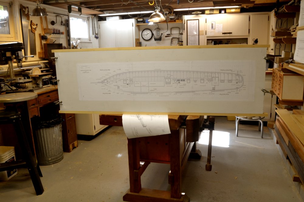
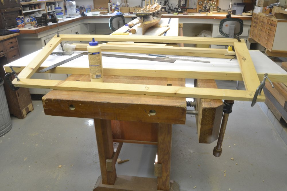
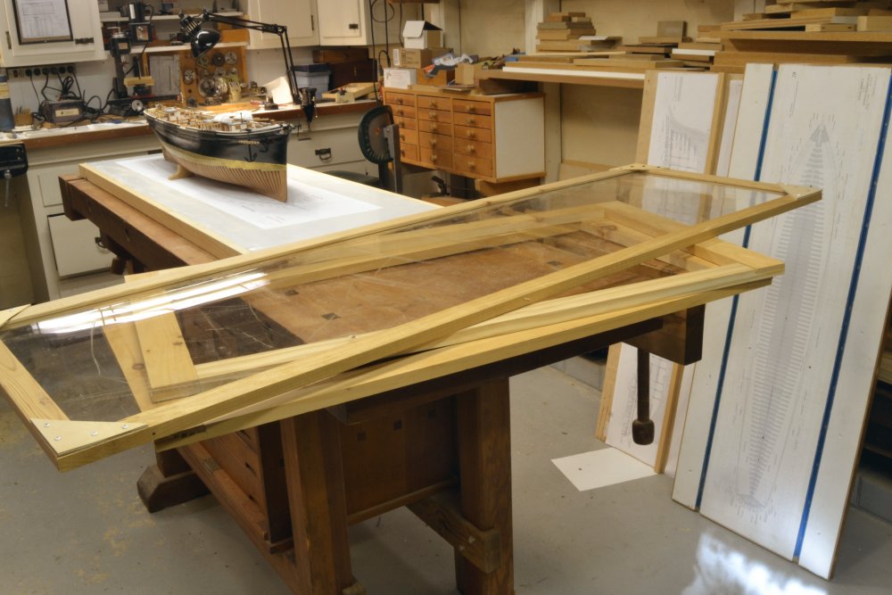
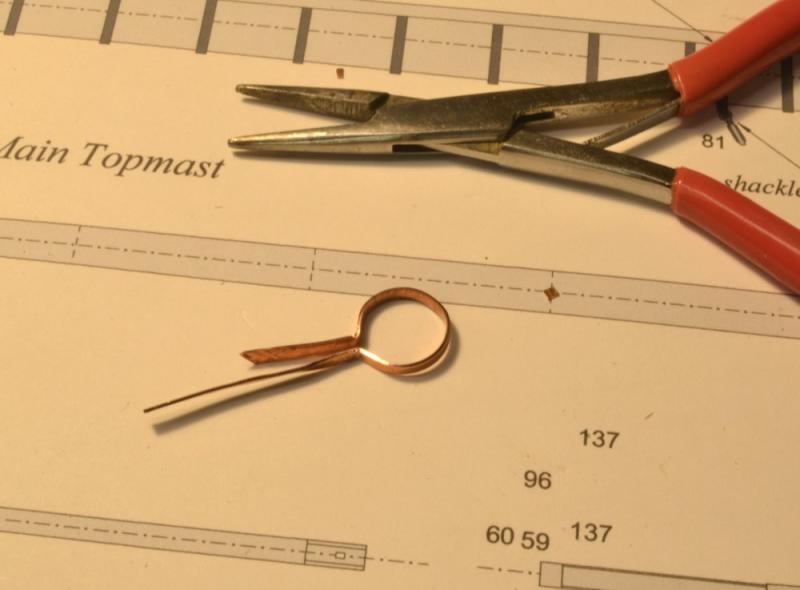
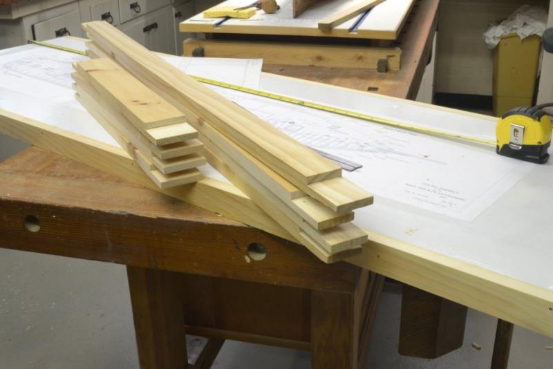
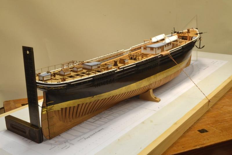
Young America - extreme clipper 1853 Part 183 – New Home Port 1 With the prospect of rigging work looming, it was time to think about a new birth for the Young America model – a new "home port." Two requirements: 1) dust protection, an enclosure that would keep dust off the model and also provide necessary access for the work. 2) a larger shipway, large enough to provide a base for the dust enclosure. The design for this is very similar to the enclosure I built for the Victory model, but larger. In that earlier box I used foam board to enclose the sides. This is larger than the standard sizes and also I wanted the inside corners to be more seamless to provide a good photographic background for the many close up pictures that I expect to take during the work. I am determined to build this entirely from scrap material of which I have a supply that needs to be consumed. The first picture shows the new shipway. The base is a disused, laminate coated, particle board kitchen panel painted with gloss white enamel. It is 61" long and 19" wide. The width will allow the main yard to be squared with its retracted studding sail booms. The length will accommodate the flying jibboom and the mizzen booms. One of the hull drawings has been pasted to this and in the picture the board is being framed with pine sides. These will keep the underside raised enough to allow the mounting bolts and also provide support for the upper parts of the case. The first work on ends is shown below. Pieces for the 42" high end frames are ready for assembly. In the next picture the lap joints of the end frames are being glued. In the next picture the model is being mounted on the new shipway. The copper wire strut is being used to very gently bring the hull into alignment using the square and triangle as guides. The three mounting bolts and single blocks screwed into the base on each side hold the hull securely in this position. The last picture shows the two assembled end frames and the top. The top frame encloses a sheet of Plexiglas® that will allow overhead lights to illuminate the model. The top has screwed corner gussets for additional rigidity and strength. The 3/16" acrylic sheet is heavy. The pieces shown may be assembled once the end panels are papered. The side panels will then be made. They will be easily removable without tools. The ends and top may also be removed with a screwdriver. Banding of the masts has been proceeding and will be the subject of the next part, but I wanted to interject this first work onn the case since it will begin to appear in pictures. Ed


- 3,618 replies
-
- 34
-
-
- young america
- clipper
- (and 1 more)
-
Thanks, Alberto, Christian, Rob, Mike, Pete and all those who hit the like button. Your comments make the work of posting rewarding. Pete, the model is going to be large - one of the reasons for including the smaller scale and simpler hull in Volume I. The next books will also include the 1:96 scale drawings and text where that is necessary. The size of the 1:72 model has come home to me with the design and construction of the dust case that will soon contain the model for the rigging work. The overall size of that is roughly 61" long, 19" wide, and 42" high. I will probably post some pics of the case project soon. Ed
- 3,618 replies
-
- 8
-
-
- young america
- clipper
- (and 1 more)
-
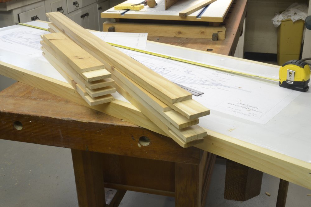
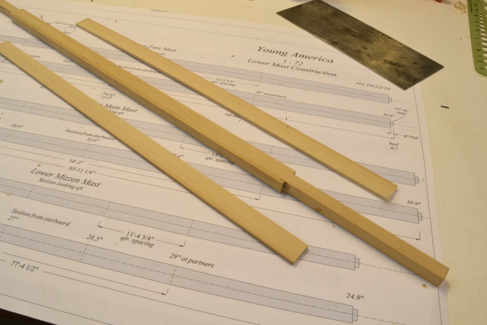
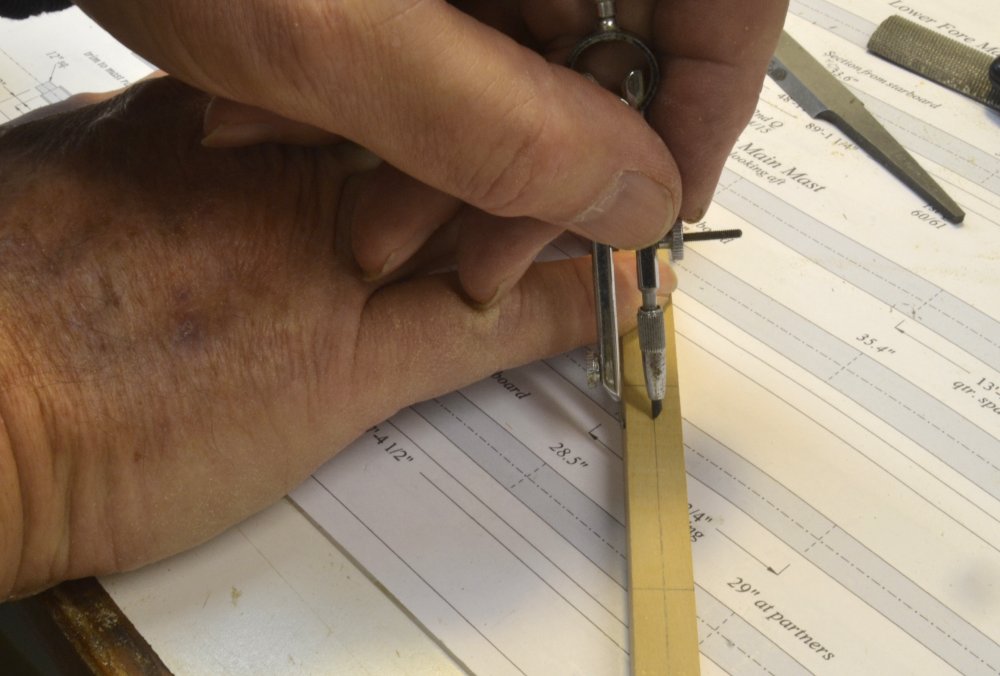
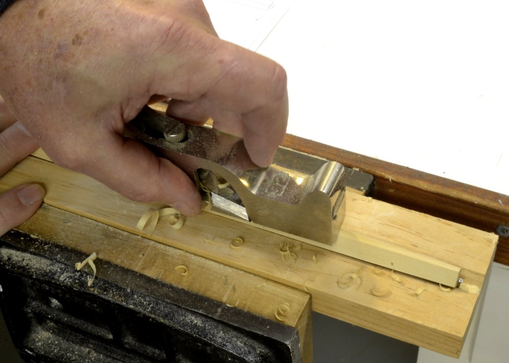
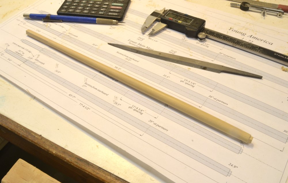
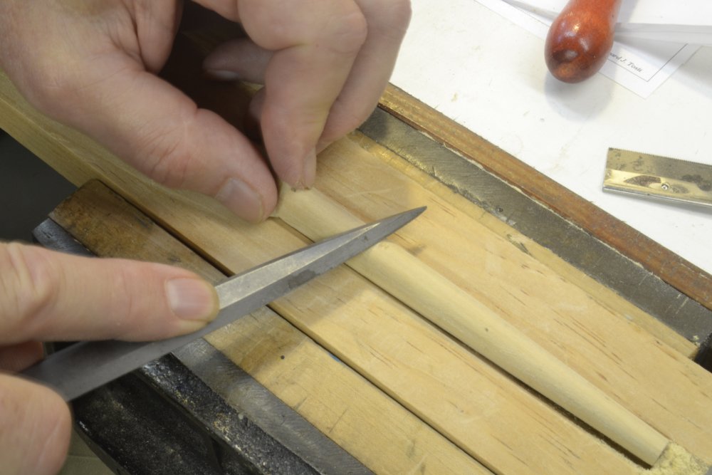
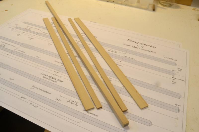
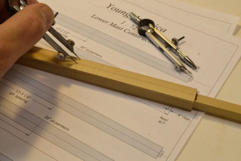
Young America - extreme clipper 1853 Part 182 – Made Masts At 36" in diameter, there is little doubt that Young America's fore and main lower masts were built up of multiple pieces – so called "made masts". Beyond that, the details of their construction is speculative. Masts were made in a variety of ways – probably dependent on the mast maker's methods and certainly on the available timber. Most made mast construction featured a central core, a "spindle" that may have been of one or multiple pieces. Attached to the sides of this were "side trees" over the lower to upper mid-length with additional side "cheeks" up to the "stop" at the top of the square "hounds" that supported the top. These might be integral with the cheeks or separate pieces. Timber pieces that filled out the fore and aft faces, "fish" completed the typical body of the mast. Often, each of these pieces consisted of multiple members. All these pieces were fitted together with a variety of hidden mortises and the pieces were often made as long scarphs. I had no intention of trying to duplicate these complex assemblies, especially without knowledge of the actual original masts. I chose a simpler design for the model fore and main masts that consists of a single spindle squared over the full length of the mast to the dimension of the doubling – the square section above the stop. Two side cheeks and two fish over the full rounded length were used to fill out the size of the squared mast that was then shaped as described in the last part. The first picture shows the five parts of the lower foremast. The next picture shows the first two sides glued to the spindle. Dark glue was used to yield a subtle joint line. These first pieces were cut just larger than the spindle so they could be scraped flush to provide a flat surface for the remaining parts. The scraper blade in the upper corner of the picture was used for this step. In the next picture the assembled stick has been marked at the quarters and on the centerline. The dividers are being used to mark the breadths at each point. In the next picture two sides are being sanded to the line – the so-called second trim. After marking these sanded sides, shaping them as above in the third trim, and then marking the apices of the octagon, the corners were removed. The first step, planing, is shown below. After forming the regular octagon, the mast was rounded using the tools shown in the next picture – a rasp, a medium flat file, and a medium-fine barrette.. The lower end of the mast is shown in this picture. It will be cut off and the step tenon formed by filing down the square spindle to the size of the step mortise. The three bare lower masts are shown positioned on the steps in the last picture. The next step on all these spars, bowsprit and masts, is the iron banding. These round hoops must be fitted over the masts before the installation of the hounds. Ed


- 3,618 replies
-
- 45
-
-
- young america
- clipper
- (and 1 more)
-
Thanks for the tip Druxey. I do have a stop (see nail) on but because its just a V-groove, the tapered spar rocks and has to be held down. I am working (i.e. thinking) about a better design - one that has intermediate supports, a better end stop and several sizes of v-groove. Too much on the plate right now - in addition to the masts, the soon to be needed monster dust case - a project that is making lots of dust. Thanks, Ed
- 3,618 replies
-
- 8
-
-
- young america
- clipper
- (and 1 more)
-
Thanks for the comments and questions, guys. Maury, the step tenon could have been milled, but I wanted to hand fit it to the step mortise. These were to be 16" square, but it has been over two years since I had access to them so I thought hand fitting (by filing) would be safest. The mizzen step in particular is completely invisible and none can be measured. They could certainly have been at least started on the mill. Turns out that all fit correctly. I started out with the tenons long until I got a fit, then shortened them to final size. Micheal, the milling base is a Sherline accessory. The clamps are from the old Unimat milling table. The hole template is great for checking roundness, but a caution: it is not good for size checking. The holes are larger to allow for the pencil point. The 1/2" hole on mine is .540". Ed
- 3,618 replies
-
- 4
-
-
- young america
- clipper
- (and 1 more)
-
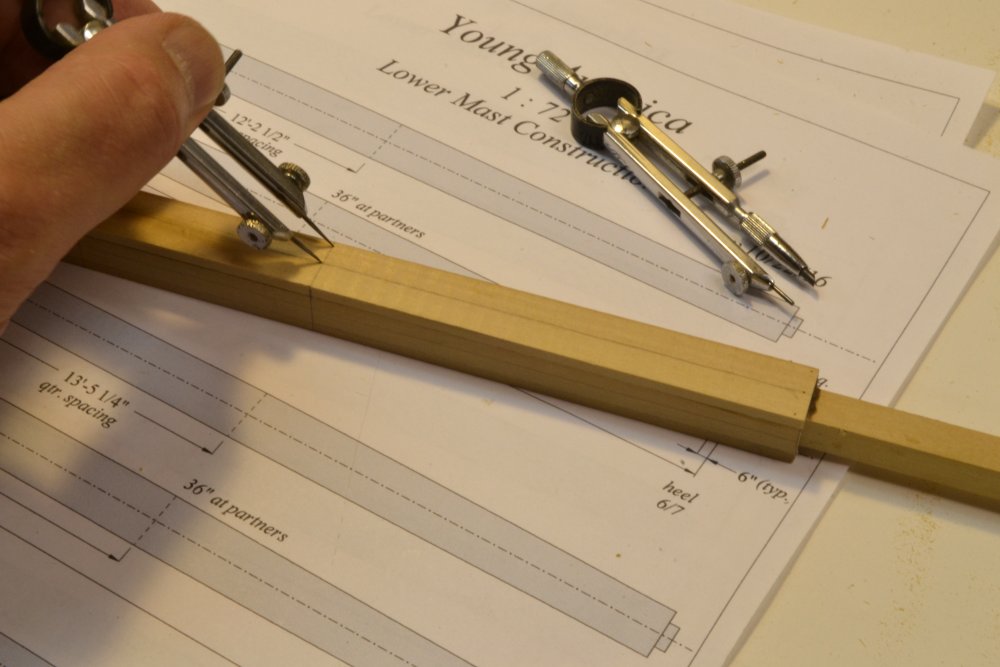
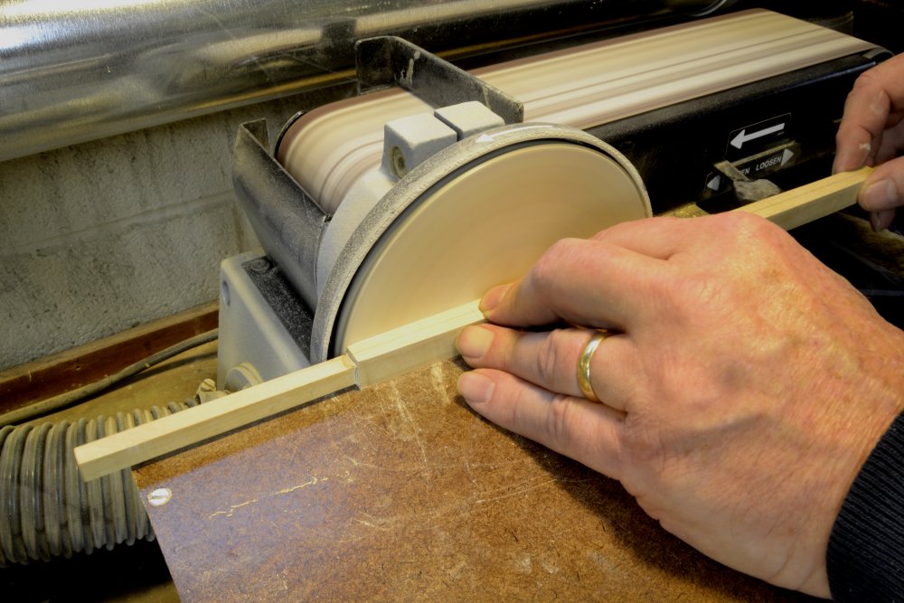
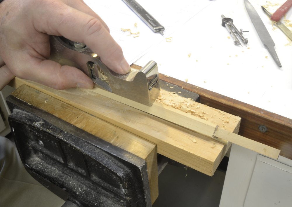
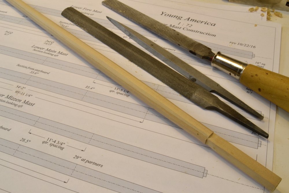
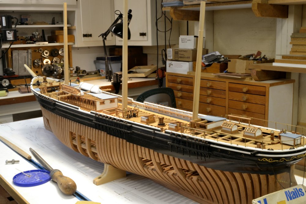
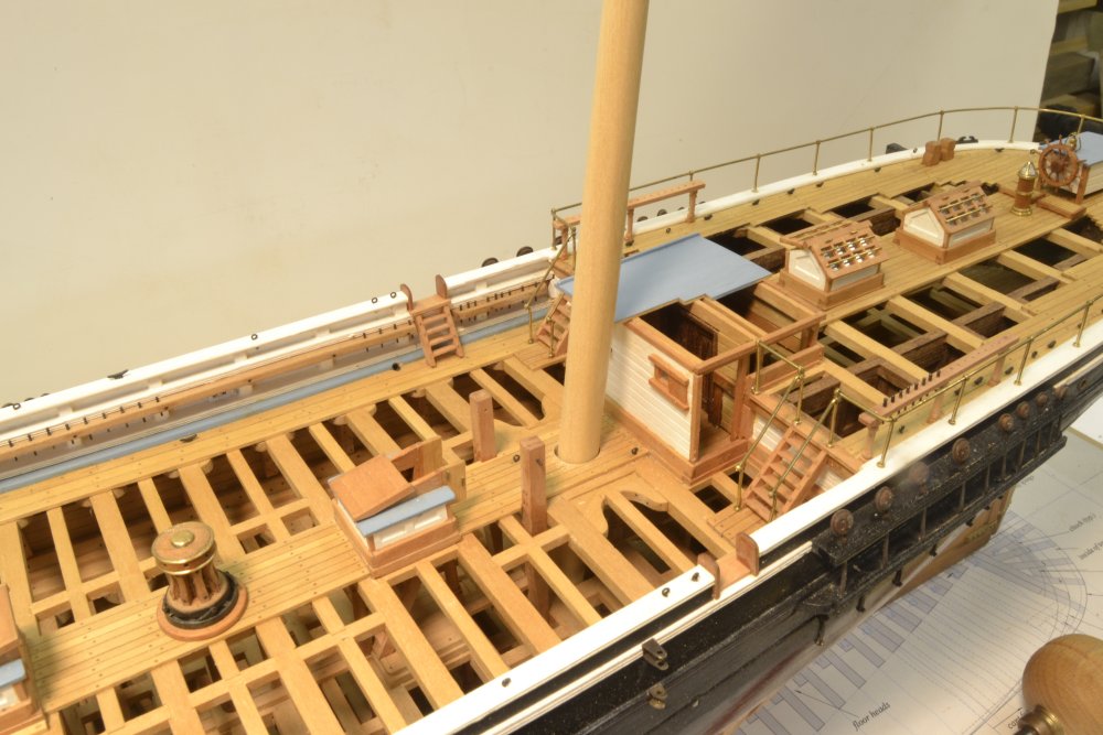
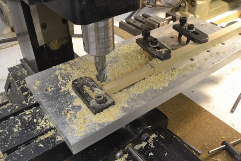
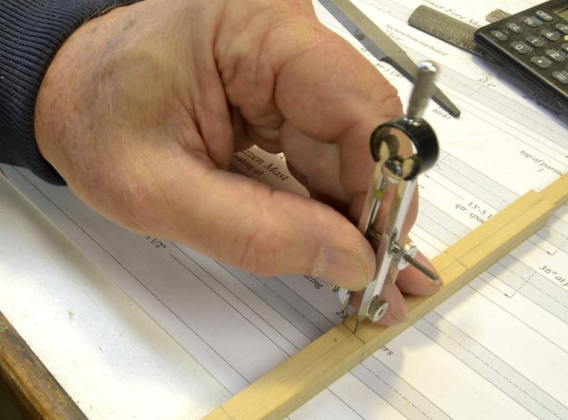
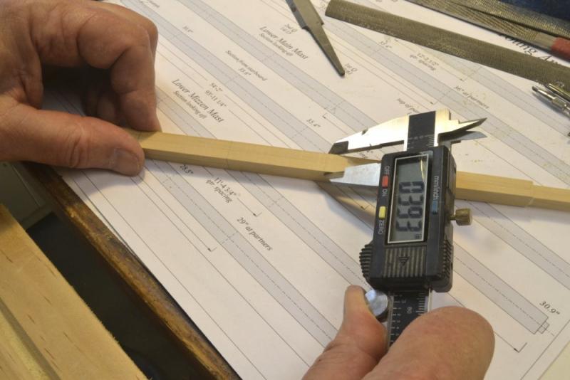
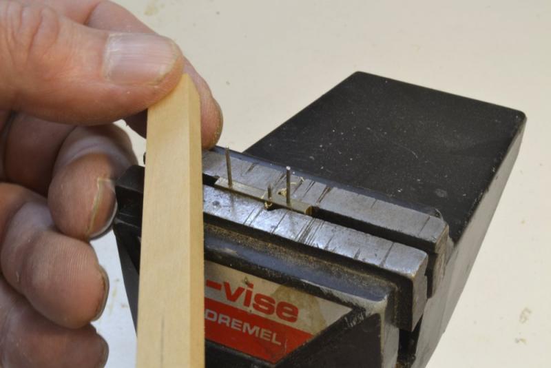
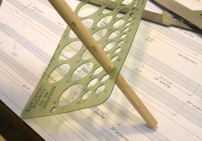
Young America - extreme clipper 1853 Part 181 – Mizzen Mast First, a word on the drawings made and used for all the spars. The lengths were based on the original builders sail plan and a spar list published at the time with a few exceptions to be described later. The diameters and other proportions were based on standard, documented practice at the time. At 78' long X 29" diameter, the lower mizzen mast was near the borderline at the time between masts made from a single tree and those built up from smaller sticks – the so-called "made masts." Longleaf pine, 3 to 5 feet in diameter and 80' to 100' feet long were available but easy to reach trees of this size were depleted by this time, requiring more effort to haul them out of the forest. Most likely YA's lower mizzen was a made mast. Because I wanted to describe both single tree and made mast modeling in a future book, I made this mast from a single stick. Subject to further research, I may band this mast as would be done on a made mast. So, making this single stick mast is described here before going on to the two other made masts. Although the trimming to size of the masthead "doubling" was normally done in the second and third trimmings, I did it right after squaring the stick to the full diameter, the first trim. Apart from the build up, this sizing method is the primary difference between the modeling of single stick and made masts. By milling the head, as shown in the first picture, I could be sure the mast would be straight over its full length and that the doubling would be square and true. In the next picture the centerlines are being drawn on the squared stick. With the quarters marked, the breadths at each were then marked out from the centerline with dividers as shown below. The indentation of the divider point was the only mark made – no lines. The next two trimmings were done to these marks on the disk sander in two separate trimmings as described in the last part (Part 180) on the bowsprit. In the following picture the trimmed breadths at each point are being checked with calipers on all four faces. Adjustments were then made to bring the breadths close to the final size by filing and/or scraping. This was the critical step in final sizing of the mast profile. To lay out the lines for the octagonal shaping, the tool described in the last post was used. It seems easier to use by clamping it in the vise and drawing the stick over it. In the next picture the octagon sides are being planed flat almost down to the scribed lines. I have small model planes, but the Stanley 92 is so precise that I normally use it wherever there is room. The octagon was finished to size, measured and adjusted, then given the fifth trimming – rounding – using files. In the next picture the rounding is being checked using the circle template. High spots are readily found by this method, filed down and rechecked. The finished stick is shown in the next picture. The step tenon was cut by trial and error until it fit neatly into the step mortise. The mastheads are chamfered to the diameter at the hounds. This is necessary not only for the usual safety reasons, but more importantly, so that the mast bands will pass over it. For the same reason, the squared hounds below the masthead cannot be installed until the bands are fitted. The next picture shows the mast slipped temporarily in place. The main deck opening will later be enlarged, the rake set, and the mast wedged in place. Ed


- 3,618 replies
-
- 39
-
-
- young america
- clipper
- (and 1 more)
-
The miracle of CAD, Druxey. I was going to attach a copy of the diagram, but when I closed the app, I messed up saving it. Operator error.
- 3,618 replies
-
- 3
-
-
- young america
- clipper
- (and 1 more)
-
Thanks for these additional comments and likes. Druxey, I think your comments on error reflect what I said initially about error increasing at smaller sizes - because the smaller size increases the angle of the spar in the device and thus, as you said, the error. Just to elaborate - at the risk of getting crazy with this. I saw two theoretical sources of error (excludes operator error): 1) the diameter of the guide rods, 2) to a much lesser extent, fact that the rods bear on the spar above and below the point marked - not right at that point. Before making the device I was concerned about the guide rod diameter, so I made some calculations: With .032" guide rods and assuming 100% accuracy at 90 deg to the line of the guides: at 45 deg the 7/24 portion is 2.6% under (.003" @ 1:72), at 30 deg the portion is 3.2% under (.0024" @ 1:72). Note that % increases but actual measure decreases. An angle of 30 deg corresponds to a spar of 50% of the markers maximum - about 1/4" actual. I believe item 2 can be safely ignored. So, I concluded the precision was adequate and went ahead and made the device. I would not, as you say, want to use this at angles less than 30 degrees - or much below 45 for that matter. So, a simple device is not so simple. Ed
- 3,618 replies
-
- 6
-
-
- young america
- clipper
- (and 1 more)
-
Thank you Maury and Gianpierro, and also for the likes on the last post. Maury, the marking tool is simple to make, but to use it takes some getting used to - and maybe there should be a version 2 that is more ready for prime time. But the idea seemed worth pursuing and it actually produced good results. The line is good for the initial trimming but is then refined by measurements around the octagon at each point. The key when scribing is to keep both guide rods engaged to the side of the piece as the breadth changes. Starting at the small end seems to help. The marker is simply a piece of 1/8" square brass drilled with three tight holes for hard, spring steel wire/rod - or nails?. The center pin is sharpened, is shorter the the guides at the ends, and is centered 7/24 of the distance from the inside of one guide to the inside of the other - not the centers. 7/24 is an approximation (7-10-7), a rule of thumb used by mastmakers. The spacing of the three holes was calculated and spaced for drilling by the mill calibration wheel. The guide spacing should be larger than the maximum spar breadth. Although it will work for smaller spars, the error increases as the spar size decreases, so a smaller one may be needed - but may be impractical to use. I will see how it works on the topmasts. Error also increases with the diameter of the guide rods. A filed point on each side may be better. Ed
- 3,618 replies
-
- 11
-
-
- young america
- clipper
- (and 1 more)
-
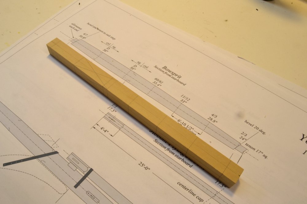
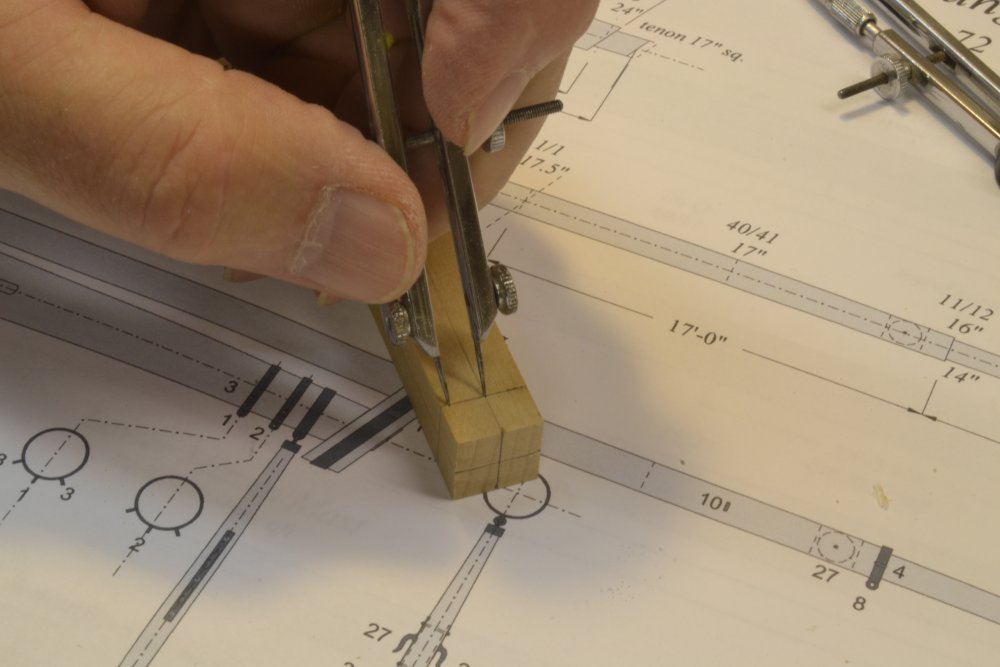
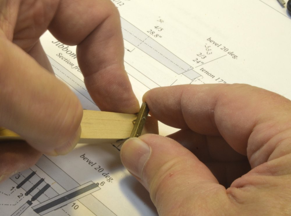
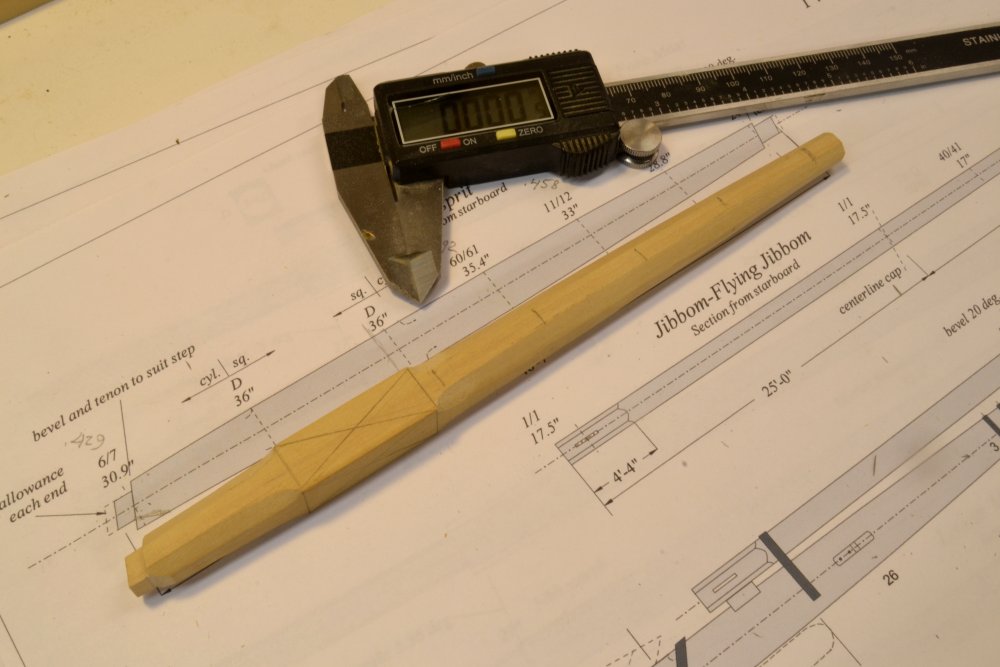
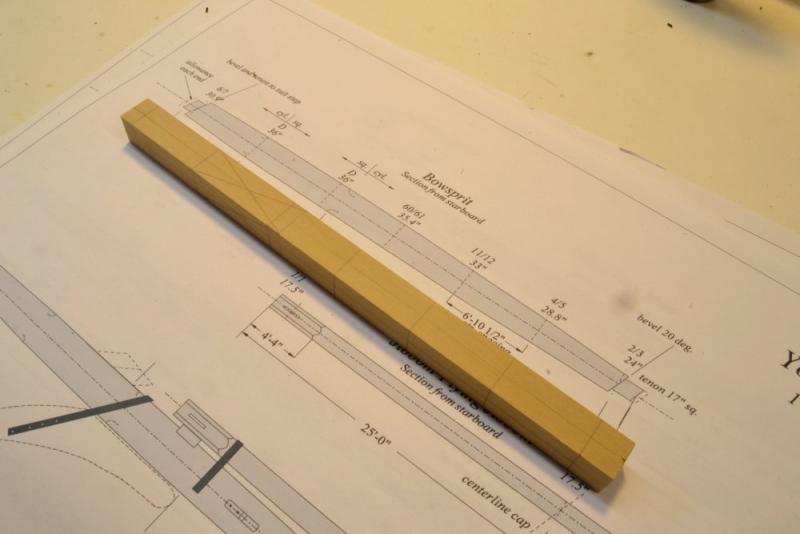
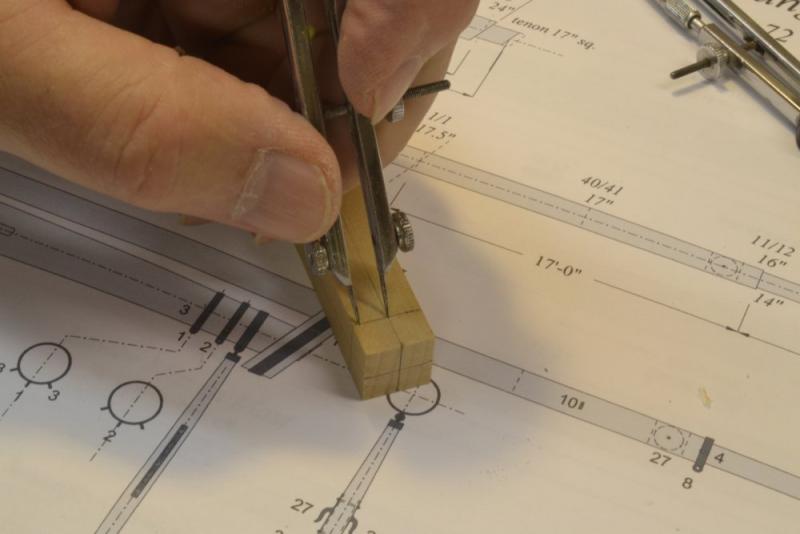
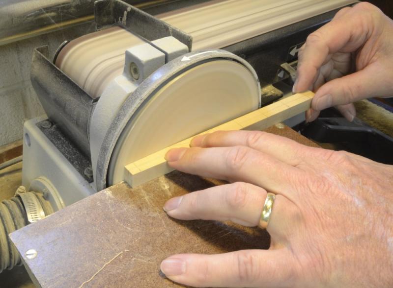
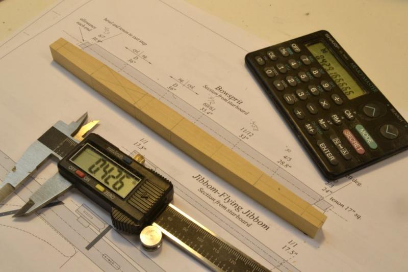
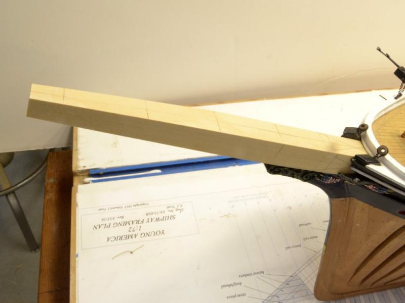
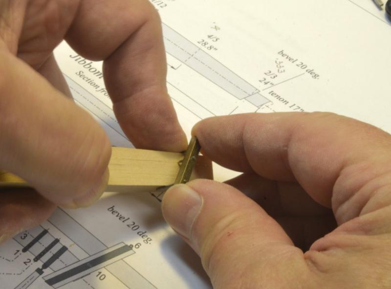
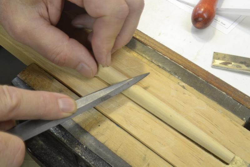
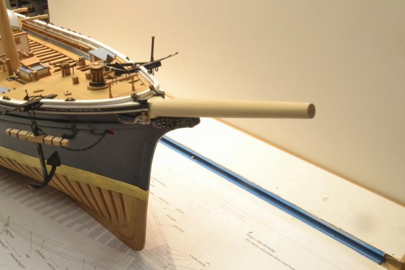
Young America - extreme clipper 1853 Part 180 – Bowsprit So, after three years and179 parts to this build log it is finally time to get off the deck. Making the largest spars – lower masts and bowsprit – is the first order of business. In shaping all the spars for the model, I expect to generally follow the methods used by the original spar makers – except of course for the tools. I expect to take some liberties with the made masts, but that will be covered later. There are many steps involved in getting from a model "tree" to a finished spar. I do not intend to cover them in detail here, but merely to provide an overview. Even at that, this posting on the bowsprit has nine pictures and a fair amount of text. I started with the bowsprit as perhaps the simplest of the large spars. At 47' long and 36" maximum diameter it was undoubtedly made from a single tree – probably of long leaf (yellow) pine. The first picture shows the spar after the "first trimming" – the point at which the tree has been squared to the spars maximum diameter and cut roughly to length. The piece has been marked on all four faces at the ends and at the four "quarters" forward of the "partners" – that is in this case, the knightheads. The square section inside the knightheads has been marked. Centerlines have been drawn on all four faces. In the next picture the breadths at each quarter and the ends are being marked on one face only with dividers set from the drawing. In the next picture the "second trimming" is being made on the disk sander. Two opposite faces are being trimmed back to the measurements made above. This tool helps keep the cuts perpendicular and fair. The next picture shows the spar after the second trim. It shows the tapers at the ends on two opposing sides only. These cuts were made just slightly full so they could be safely finished to the final dimensions in later steps. The calipers and the calculator are key tools for this. The converted dimensions may be seen in pencil on the drawing. In the picture the trimmed faces have been marked with centerlines and quarter marks. The breadths at each point were then marked on the trimmed faces, so the "third trimming" could be made on the remaining two sides – also on the disk sander as before. The bowsprit after the third trim is shown fitted part way in position between the knightheads. The next step – the fourth trimming – converts the still square areas (except at the partners) to an intermediate octagonal shape. The trimming is done by hand – planes, rasps, files, scraper plate. To provide some rough guide lines for that work, the tool shown below was useful. The apices of an octagon are 7/24 of the diameter in from the sides of the square at each point along the curve. The tool shown has a scriber point at 7/24 distance from one of two end guides. By angling the tool as it is drawn along the spar, a 7/24 line is scribed. This takes some practice and is a rough measure – but a very helpful one. With lines marked on each face of the square section, the octagonal flats were cut and the spar trimmed as shown below. A lot of caliper measurements and fine trimmings are required to get the spar to this point. The diameters of all the faces at each point are measured and trimmed to size. The final, "fifth trimming" is being made below. The apices are being filed off and the spar rounded. Again the diameters at each mark are checked. Roundness along the spar was checked using a draftsman's circle template to spot high areas. The last picture shows the bowsprit fitted temporarily with its tenon seated in the step above the main deck. In the picture the bowsprit has been sanded but not polished and the tenon for the cap is not yet cut. Ed

- 3,618 replies
-
- 48
-
-
- young america
- clipper
- (and 1 more)
-
You've got some interesting problems, Micheal, and your just getting started. I've been thinking about your wire problem and don't have a solution to offer, but maybe a couple idle thoughts: I just bought some 316L stainless 36 gauge wire from Amazon that I may twist into cable for YA's wire rigging. Something to consider if you decide to replace all the cables. Small gauge copper and brass bare wire are available. I don's use coated wire, but there are small sizes in silver craft wire. One idea I've never tried: Stretching - re-annealing - re-stretching wire to get to the right size? Use of a drawplate? On the hull paint job: I would have a go at filling and touching up the damage before resigning to a full repaint. You said the finish was brushed. Presumably enamel. The black should be easy to match, followed by rubbing out with abrasive pads to blend. May work. Replicating the copper color of the hull may be a different matter. I admire your commitment to a job like this. Its something that would put me away. Ed
- 749 replies
-
- 5
-
-
- albertic
- ocean liner
- (and 2 more)
-
Beautiful pins, Frank. I'm glad the method worked out for you. Its not fully automated, of course, so some art and a good eye is needed to make consistent pins, especially if they are not going to be covered with rope. Great work. Ed
- 649 replies
-
- 7
-
-
- dunbrody
- famine ship
- (and 2 more)
-
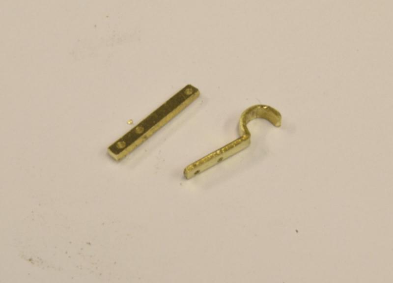
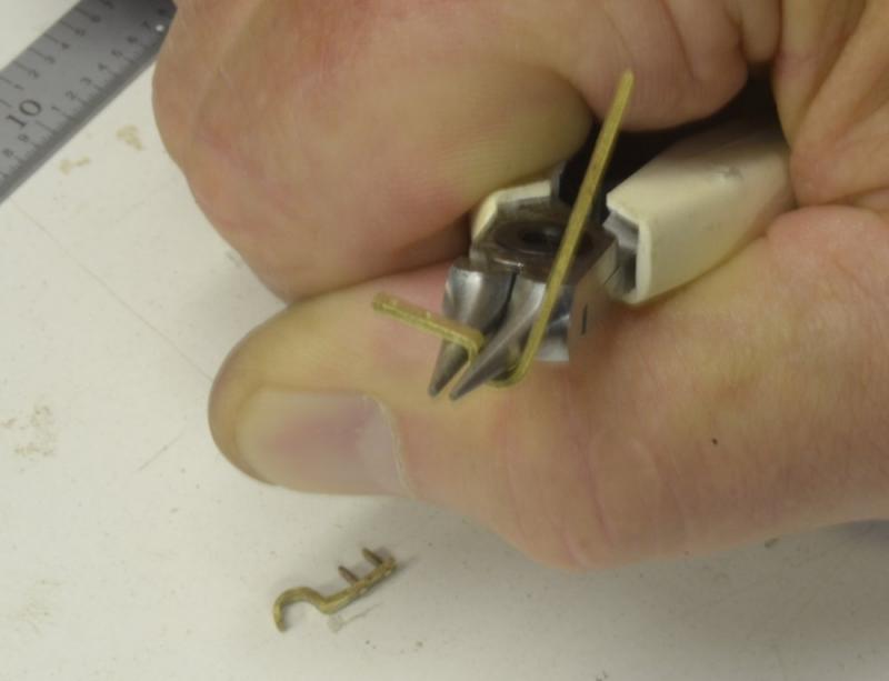
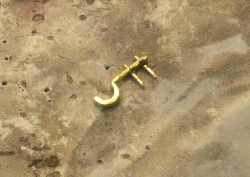
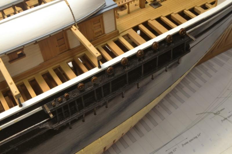
Young America - extreme clipper 1853 Part 179 – Swinging Boom Hardware Another small detailing chore. The primary purpose of the lower studdingsail booms, commonly called swinging booms in this period, were to secure the feet of the studding sails sometimes used on either side of the foresail, and less commonly outside the mainsail. These booms were also sometimes deployed in port for the mooring of small boats. I expect to store two of these booms on the cabin deck skid beams and include hardware to support them on the fore channels only. The first picture shows the iron brackets at each end the port fore channel. The forward bracket is simply an iron bar with a hole to accept a gooseneck at the end of the boom. At the aft end of the channel is an iron cradle to support the boom when fitted but not extended. Both fittings are bolted through the channels. The next picture shows one set of roughly formed fittings. The support bracket to the right is being formed in the next picture, beginning with the bending of a right angle. After bending the brass strip, it is hammered in the vise to form a sharp angle. The round cradle at the end was then formed as shown in the next picture. The end of the strip is left long to facilitate bending of the curve. The bracket at the bottom of the picture has two bolts fitted. In the next picture a fitting is set up for soldering of the bolts. The bolts were then filed off and the pieces finish filed and buffed, pickled, degreased and blackened. The last picture shows the starboard fore channel with the brackets installed. Ed


- 3,618 replies
-
- 30
-
-
- young america
- clipper
- (and 1 more)
-
Rob, I am quite certain that this model was used to shape the hull and then to take off the offsets. This process did not require tracing of segmented lifts but could be done from measurements. Either process may have been used. The segments could have later been assembled and finished. I expect that the model was given some detail as shown for purposes of describing it to and negotiating with the owners. I assume the scale to be 1:48. This process was common practice by Webb and very likely other American builders and perhaps Brits as well. Ed
- 3,618 replies
-
- 4
-
-
- young america
- clipper
- (and 1 more)
-
Thank you, Glenn. Most kind. When I saw over 50 notifications in my box, I figured someone was doing some catchup. Rob, the picture is attached. Look familiar? Ed

- 3,618 replies
-
- 13
-
-
- young america
- clipper
- (and 1 more)