EdT
-
Posts
2,214 -
Joined
-
Last visited
Content Type
Profiles
Forums
Gallery
Events
Everything posted by EdT
-
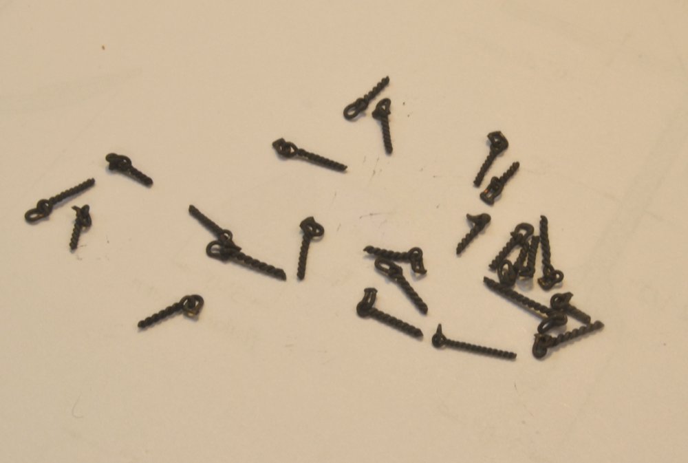
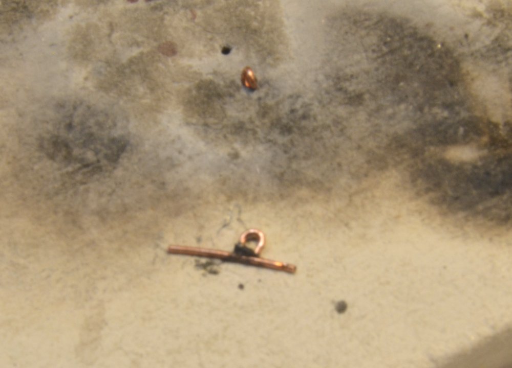
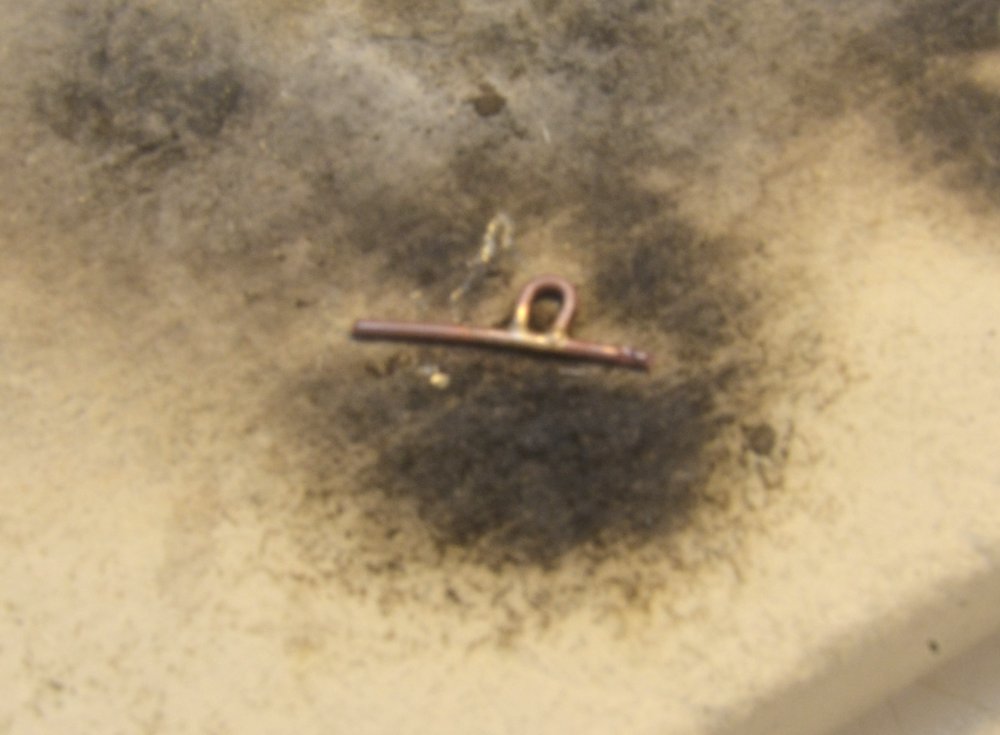
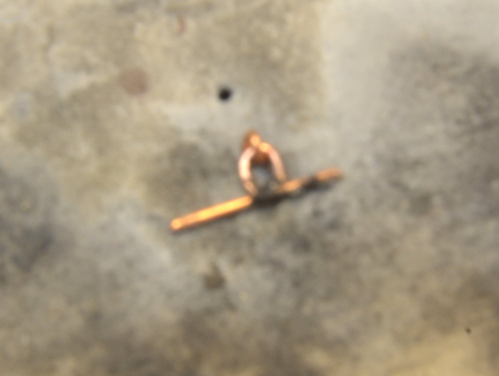
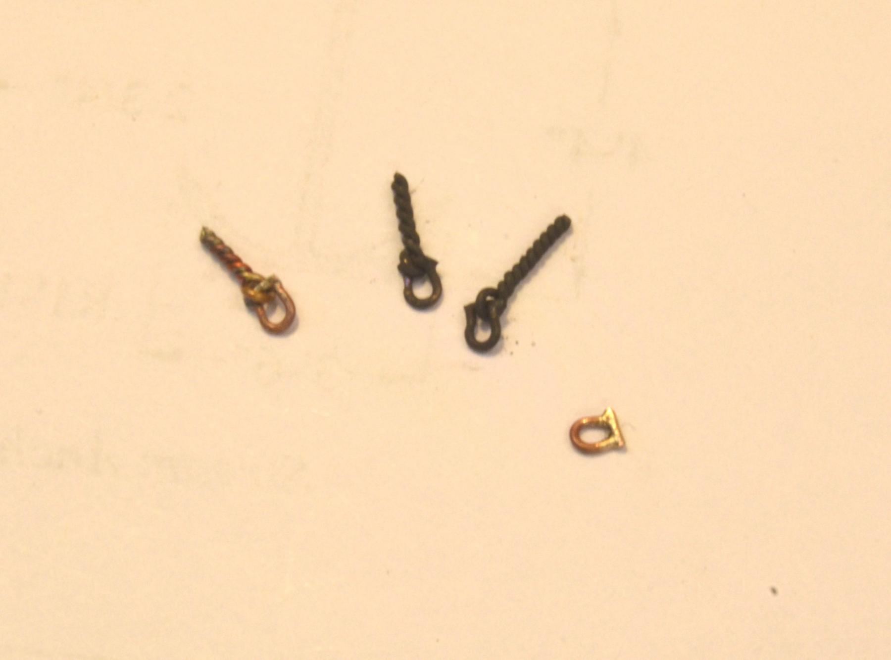
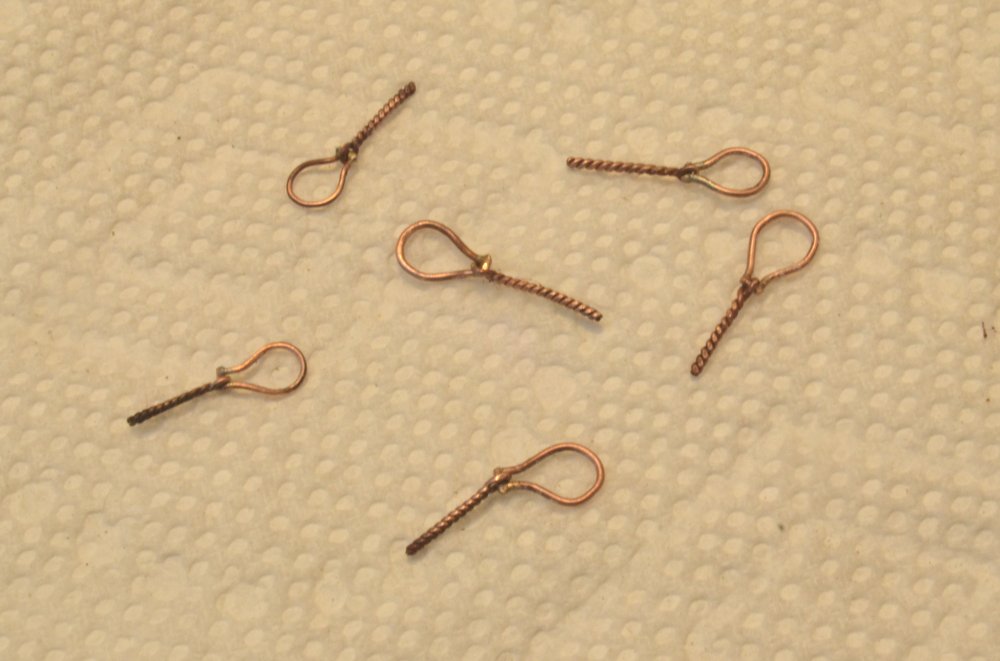
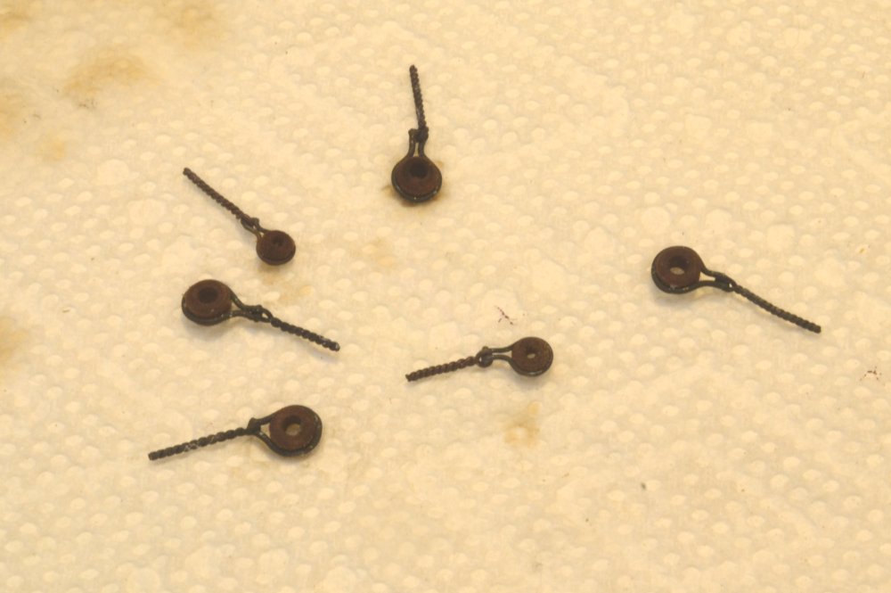
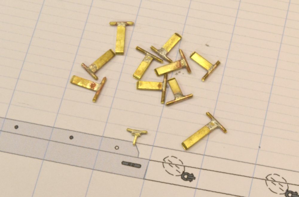
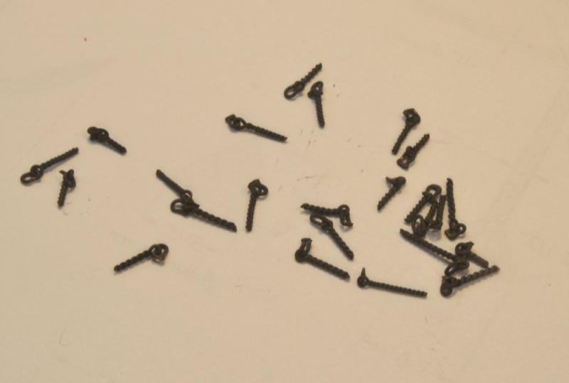
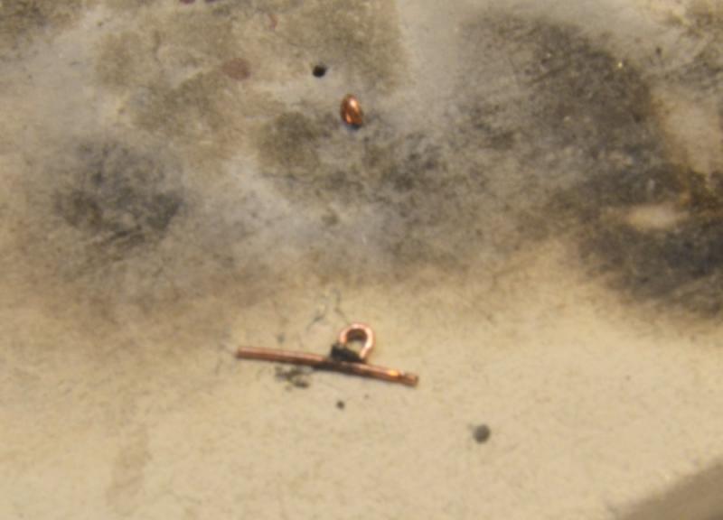
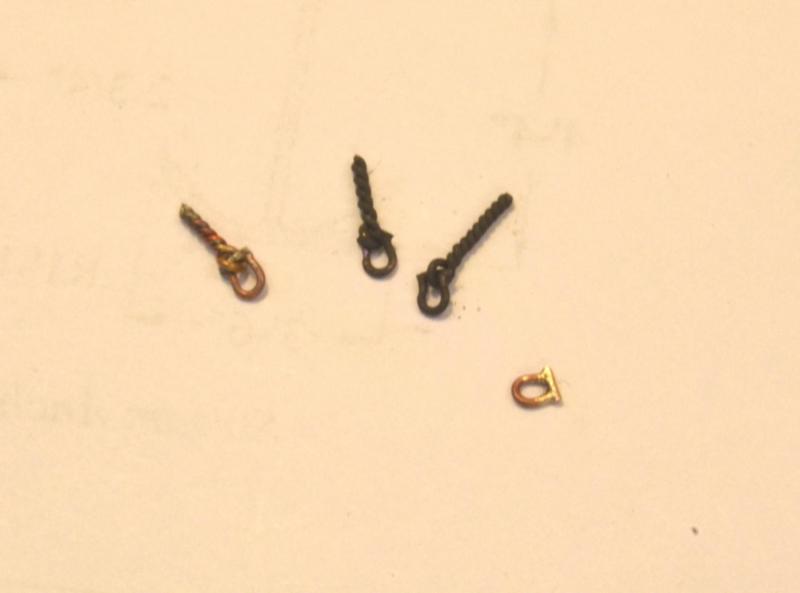
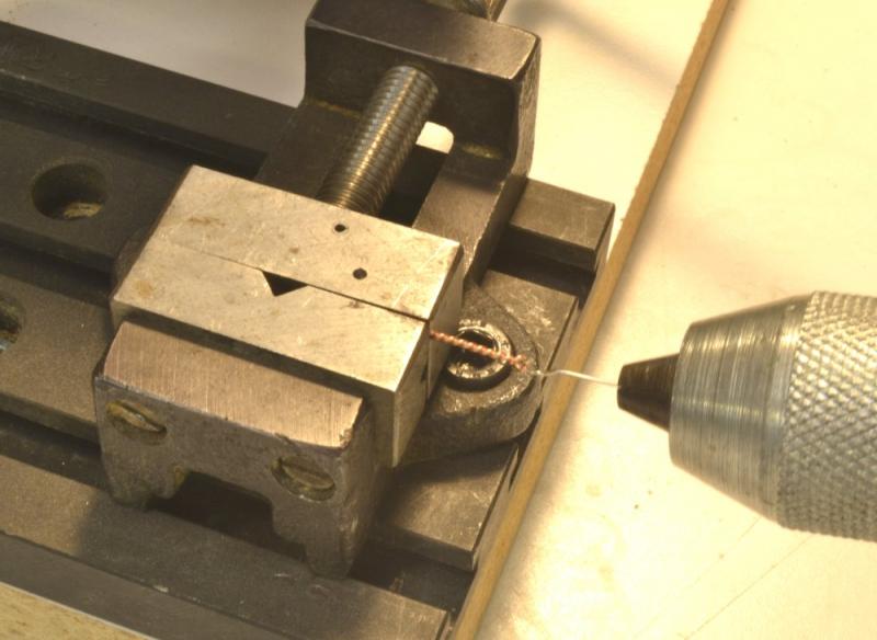
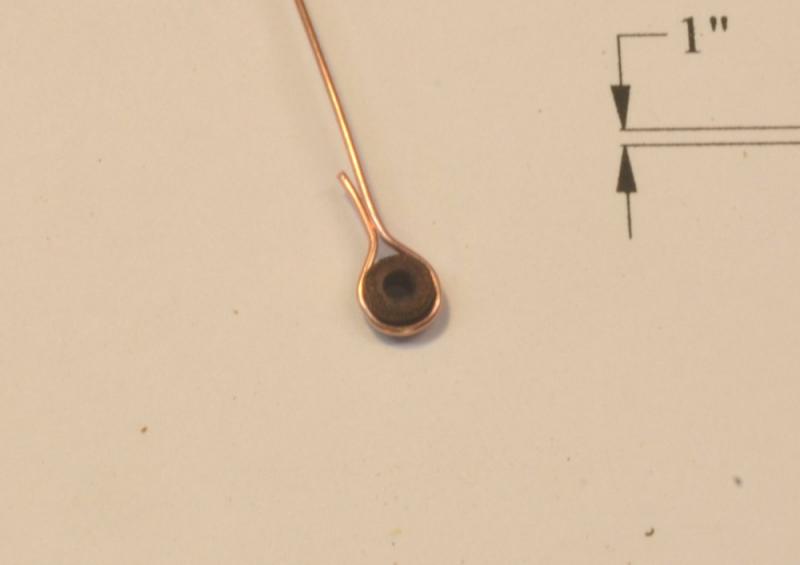
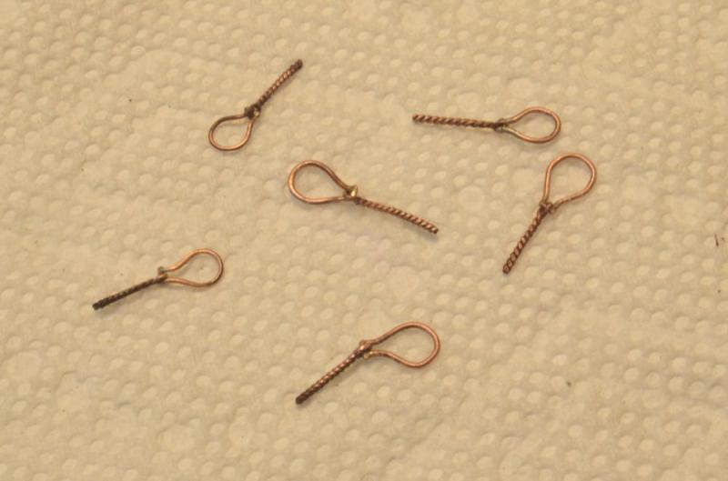
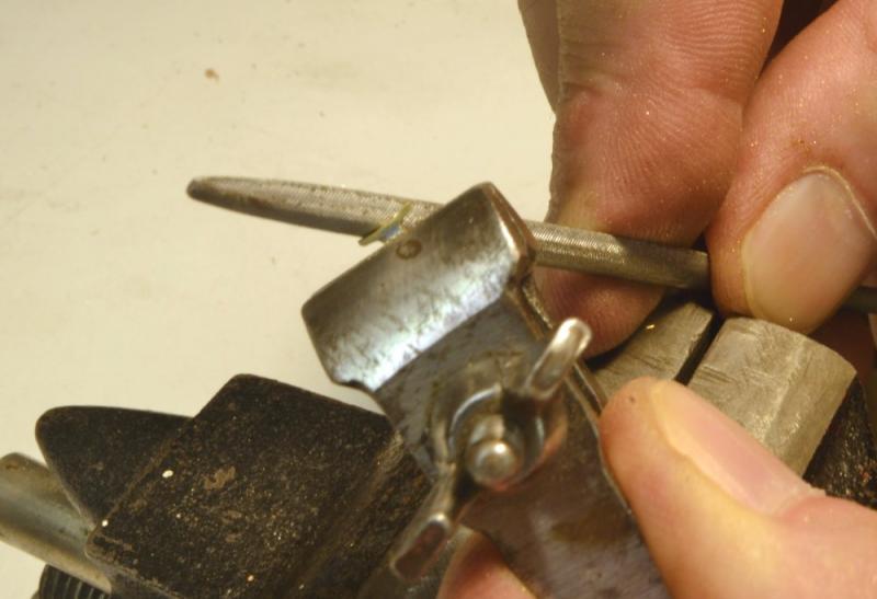
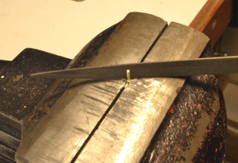
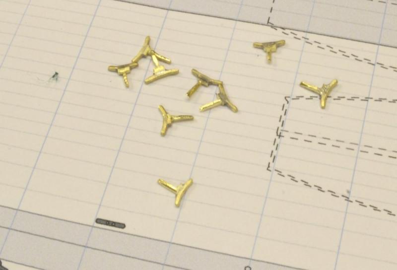
Young America - extreme clipper 1853 Part 175 – Shackles Since I will be away for the next couple weeks, I thought I would cram in one more post before leaving – especially since it relates closely to the last post. There will be many shackles like those described below in Young America's rigging – 3 dozen or more on the deck and hull, plus many more aloft on yard bands, connecting chains and wire to rope, etc. Shackles consist of U-shaped iron yokes with screwed bolts threaded into the ends. They replaced ring bolts, seized lashings and other connectors. Easy removal of the screwed bolt allowed connections and disconnections to be made easily. Several shackled eyebolts are shown below. These will eventually be installed in the deck, rails, or hull by the method described in the last part – but not until later after the lines have been spliced on at the workbench. The next picture shows the two parts of a shackle about to be silver-soldered. The two pieces are 24 gauge copper wire – same gauge as the eyebolt. Copper-phosphorus paste has been applied at the joints. The configuration of the pieces is intended to simulate the horseshoe shape with a straight bolt at the bottom. The picture also shows an eyebolt embedded in the soldering block ready for attachment of its shackle – not the one shown. The next picture shows the soldered shackle before trimming the bolt ends. There will be relatively few of these standalone shackles, so this was for demo only. The next picture (apologies for bad focus) shows the soldering setup for an eyebolt-attached shackle. The embedded eyebolt must be kept clear of the solder paste so the parts will swing freely. After soldering, the shackle must be rotated so its bolt passes through the eyebolt allowing the rope or other line to connect to the horseshoe loop. This rotation has been done on the pieces in the last picture. The loops on these shackles at 1:72 are about 6" (.08" actual) diameter. Next topic: Whisker booms. Ed


- 3,618 replies
-
- 37
-

-
- young america
- clipper
- (and 1 more)
-
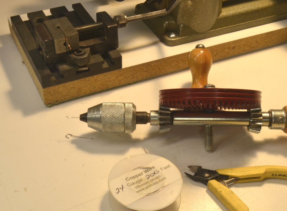
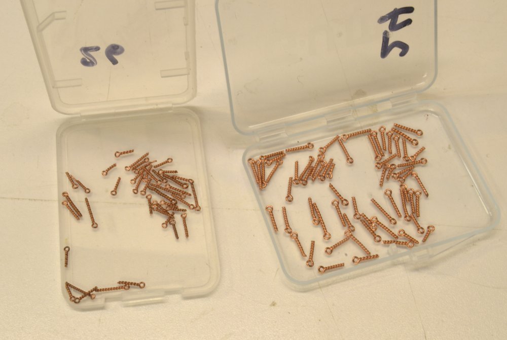
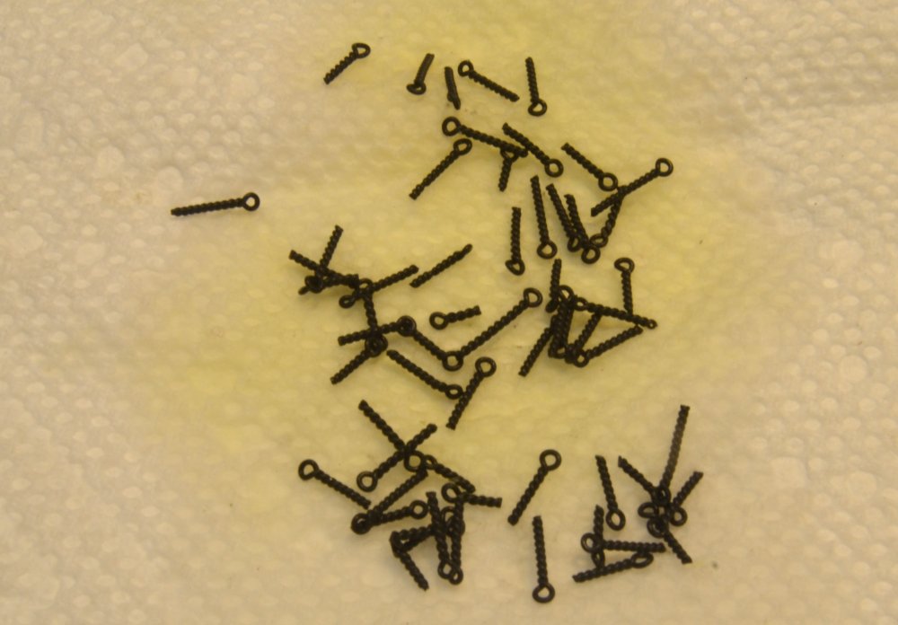
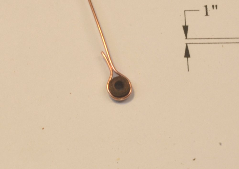
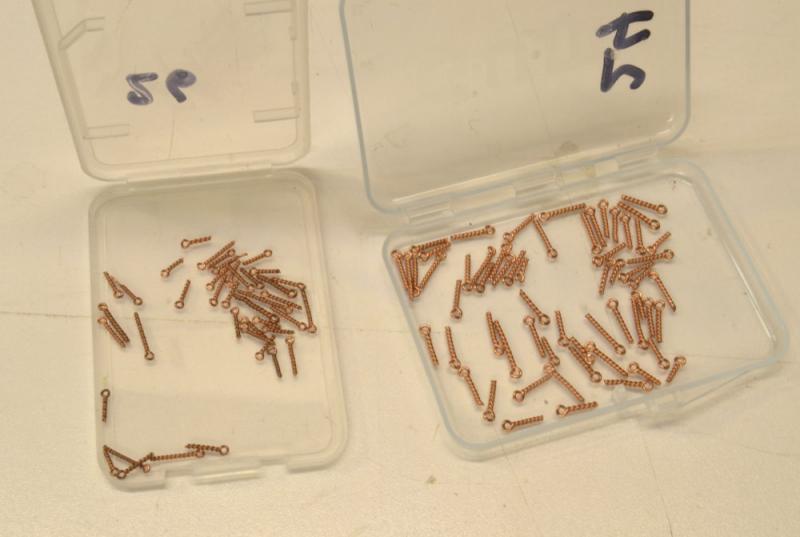
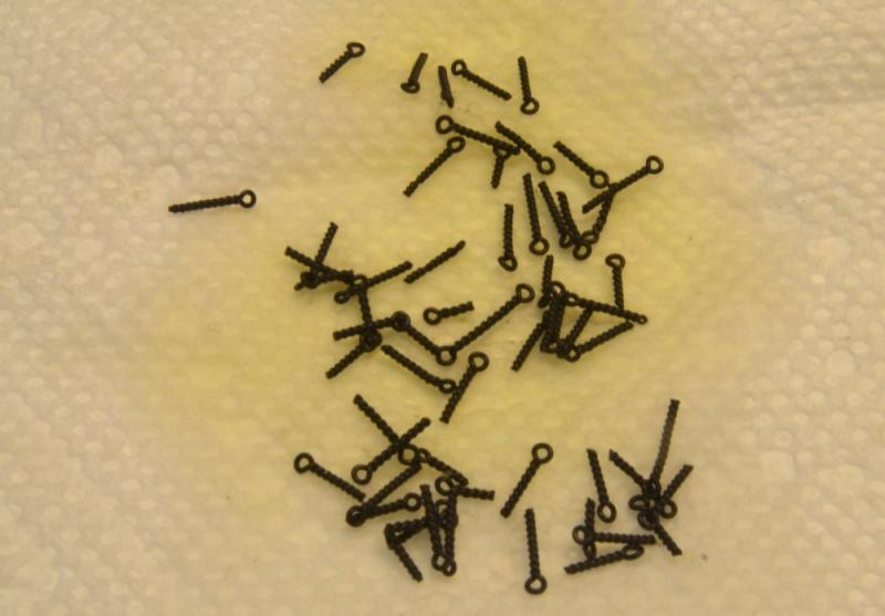
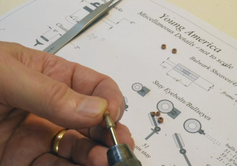
Young America - extreme clipper 1853 Part 174 – Eyebolts There are about 5 dozen eyebolts to be mounted on the deck and rails. These are eyebolts to which rigging lines, mostly for tackles, will be secured by hooks. There are another 3 dozen or so to which lines or chain will be shackled. Since the shackles will be non-working, these latter eyebolts may not be permanently fixed until the lines are attached, mostly by splices and thimbles, block straps, seized ends or chain links. Making these connections in place is not an option for me so the connections will be made before the shackle eyebolts are fitted. The unshackled eyebolts, however, may be installed at this time. The rigging drawings necessary to place these are complete. I made the 60 eyebolts in about an hour by the method shown below. They were made by spinning 26 gauge copper wire. The eyes are about 5" O.D. The first picture shows the tools and raw material. The hand drill is fitted with a hook made from a pleating pin. A slightly larger diameter hook is also shown and was used for the shackled eyebolts that will be described in a later post. For convenience I used the Unimat® vise set up as shown. A short piece of wire is bent and the ends secured in the vise. The next picture shows an eyebolt being spun. The amount of spinning becomes a matter of judgement. The next picture shows two sizes of eyebolt. The smaller size to the left was made from 26 gauge wire. All of the deck and rail mounted eyebolts are 24 gauge, 5" O.D. The next picture shows these blackened using liver of sulfur. The bolts all have the same diameter shafts, with some variation in O.D. However, all these were deemed acceptable for use. The O.D. at 1:72 scale is about .07". Holes were drilled for a slip fit with some friction. After drilling the eyebolt was dipped in medium viscosity CA and pushed into the hole with pliers. The next picture shows four of these around the fore mast. There is, of course, a slight twist to eyebolts made by this method, but at this scale I felt it was acceptable. Apart from the ease of making these, they also have advantage of eye strength without soldering, and gripping strength in the holes. The next picture shows some of these in the main rails, in the outer binding strakes, and around the mizzen mast. There are also several bolted through the channels and several around the poop rail and outer deck strakes. There are a few on the exterior of the hull but most of those will have shackles attached. Another pre-rigging chore completed. Ed

- 3,618 replies
-
- 39
-
-
- young america
- clipper
- (and 1 more)
-
Masterful job, Alexandru. Ed
-
Allan, Thanks for your further comments. Soon I will be building a dust case for the rigging work that should solve the background problem. I plan to use sheets of the photo background paper on the wood-framed sides and ends with clear Plexiglas on the top for light. Sides will be removable for work but with the paper installed correctly at the corners I hope to get a good all around, uninterrupted background as well as dust protection. I did this when rigging Victory using white foamboard and it worked well. This one is too big (56"L x 36"H x 18"W) for standard foamboard . I had to look closer at your avatar to figure out that you have perhaps turned into an alligator? Ed
- 3,618 replies
-
- 4
-
-
- young america
- clipper
- (and 1 more)
-
Thank you for the pics, Allan and Rob. Allan, good to hear from you. Euryalus looks great in that picture - had not seen such a good color shot before. Actually, both models look great. I have a large (60" wide) roll of backdrop paper that I use for finished photos, but for the everyday pics (usually 6-10 per day) its not practical to use. I like the picture of the chapelled mast, Rob. The drawing should be credited to George Campbell, by the way. I am aware that bolting was used in addition to the hoops. Bolts went in before hoops, but the question is which came first in a made mast, assembly or rounding. No one seems to say explicitly. Bolts would definitely interfere with rounding if installed before. For modeling, this may be academic. I expect to assemble the pieces, then round the masts, then add bolts and hoops - and as I said, based of photo evidence - I do not intend to chapel the masts. michealpsutton2, just to keep the record straight, the model mast pictures are Rob's, not mine. Ed
- 3,618 replies
-
- 5
-
-
- young america
- clipper
- (and 1 more)
-
Hi Maury, Looking really good. I really like those foam sanders as well. I believe I ordered mine from Highlandwoodworking.com some years ago. With the ribbands I see in the pics and the keelson installed, you should be able to remove the spacers without difficulty. More support in the form of longitudinal members is always better, but the deck clamps may interfere with removing the spacers if you wait for that. Cheers, Ed
- 525 replies
-
- 2
-
-
- anchor hoy
- hoy
- (and 1 more)
-
Thank you, Nils. I am sure you are well aware - with the size of your models - how awkward it can be to get photos of the full model - especially if you have a cluttered shop as a background as I do. I expect this will be even more of a problem for the rigged model, although I intend to fully encase it before rigging begins. The main cabin left me with a dilemma. It is so large that it becomes a real barrier to viewing the structure below, so cutting one side away seemed appropriate. At the same time, including internal detail would have equally blocked the view, so I left it open and unfurnished inside. The goal has been to present a finished look, except for the lower hull, from the starboard side and more open structure on the port side. That was also the approach on Naiad. Ed
- 3,618 replies
-
- 6
-
-
- young america
- clipper
- (and 1 more)
-
Thanks, Guys. It was a rare moment in the shop. Bob, shellac is a good sealer and a good primer for just about any non-penetrating finish - paint varnish, acrylics, etc.. It can also be sanded and polished and will always be dissolvable in alcohol. It is also a good stain blocker before painting over knots, etc. It does yellow. It is a fast drying, surface finish, so on the decks it would have to be brushed out thoroughly which is not easy - or buffed when dry - also not easy with all the obstructions. I tried some thinned polyurethane on the forecastle, but was not satisfied for these reasons, hence the thinned oil. This left a very uniform finish, so unless I have some bonding problems later, I will be happy with it. I would have waited if I had any wood to wood gluing left to do, however. There is no question that glue will not bond to wax - at least no glue I know of. On the book, my guess is sometime in the first half of 2017, but no scheduling has been done yet and right now the ball is still in my court to produce the manuscript and enclosures. Ed
- 3,618 replies
-
- 7
-
-
- young america
- clipper
- (and 1 more)
-
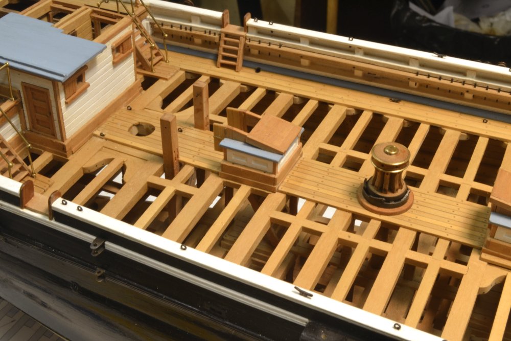
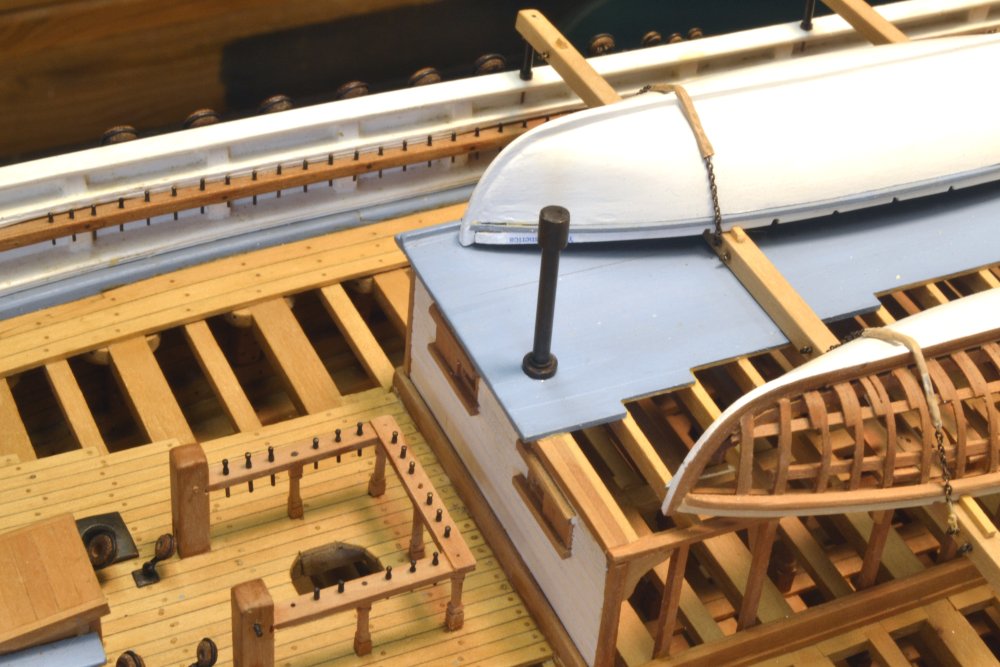
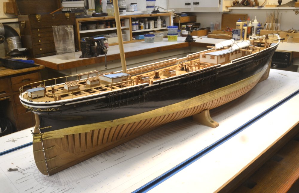
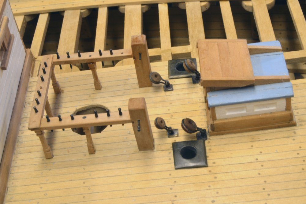
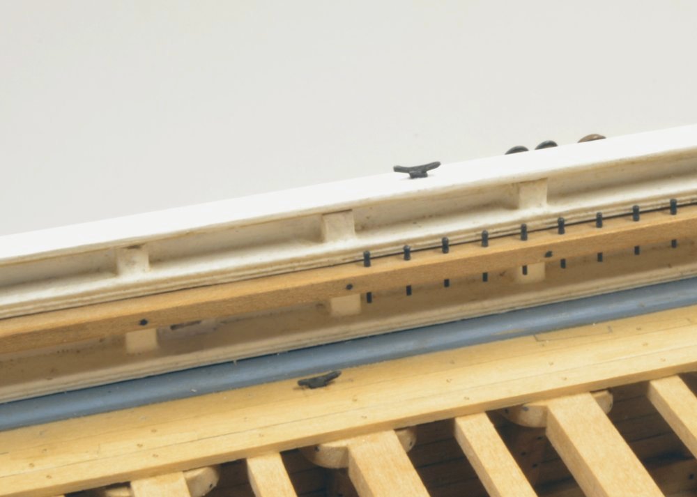
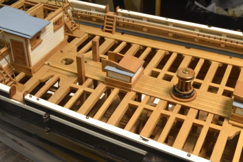
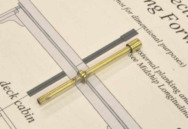
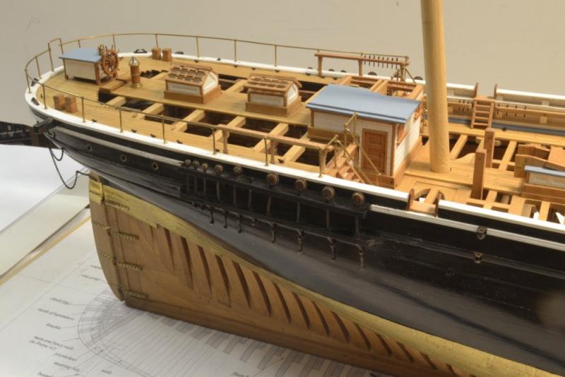
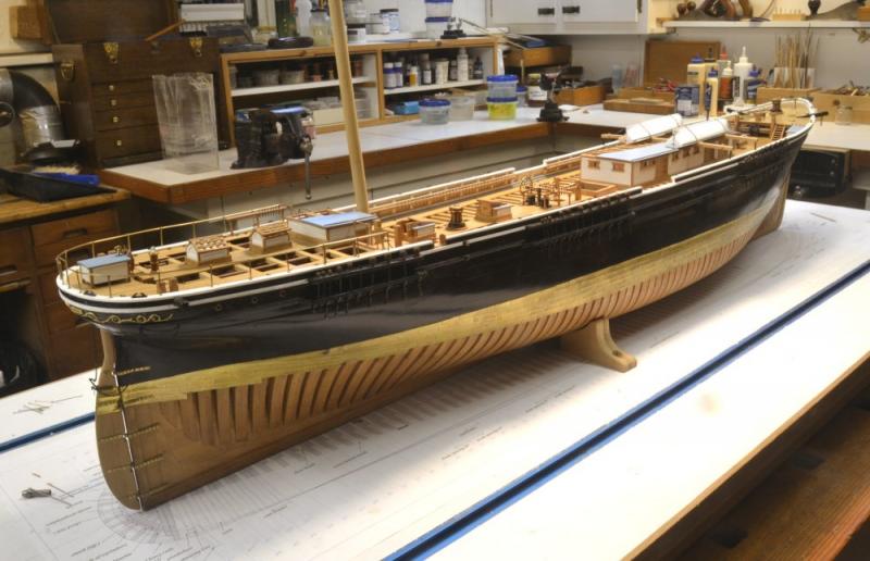
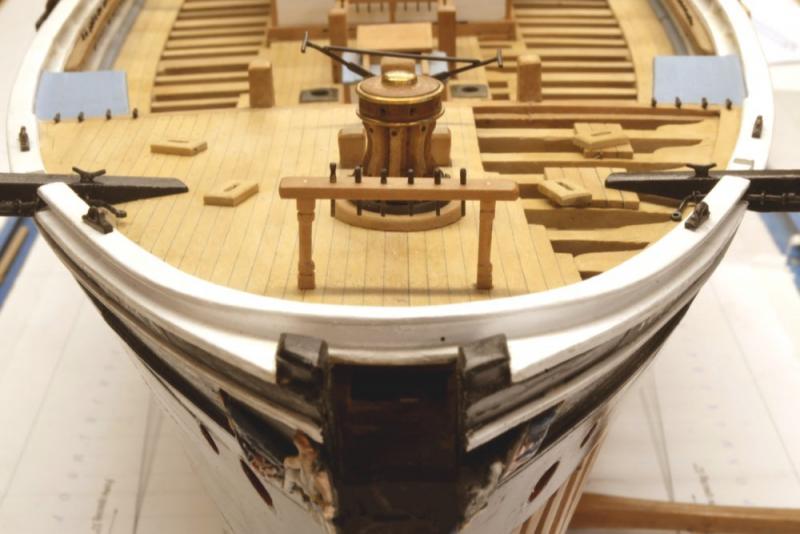
Young America - extreme clipper 1853 Part 173 – Stovepipe/Channels A short update. I am sure I have mentioned that my present goal with the model is to complete the work of fitting out the hull and decks in preparation for masts and rigging. Completion of this work will define the endpoint of Volume II of Modeling Young America, and the starting point of Volume III. We're getting close, with only the deck and hull eyebolts and a few other small chores remaining. One of the minor chores was making and fitting the stovepipe through the roof at the forward end of the main deck cabin. This was made as a fabrication of pieces of telescoping brass tube segments – a convenient fabrication method. The first picture shows the stack before blackening. The design is based on the two photos of the ship. Three sizes of tube were used, plus a segment of solid rod to close the top of the diffuser cap. The next picture shows the installed stack. The simulated flashing at the base helped secure the stack in a drilled hole. This week the channel deadeye installations were also completed. The next picture shows the starboard mizzen channel and deadeyes. Deadeyes on all channels range from 16" (.22" actual) to 6" (.08 actual). The largest on the mizzen channel shown above are 13". Making the deadeye chains was described in an earlier post. A number of eyebolts are yet to be installed in the channels. The last picture shows the model at the current state. Another bit of work that may be noticeable to some followers of the project is that the decks have been finished with a single coat of diluted Tung oil. The open pores of the unfinished decks were beginning to accumulate dirt. The finish has darkened the Castello decks slightly, evened out their finish and will make them easier to keep clean. I did not use the usual wax finish because I am anticipating gluing some rope coils later and I believe with the right glue they will hold on the (by then) polymerized Tung oil. Anyway, the decks had to be finished. Ed

- 3,618 replies
-
- 36
-
-
- young america
- clipper
- (and 1 more)
-
Rob, just a further comment to better address your question. I believe what you are describing is "chapeling". There is no sign of this on the Young America photos and I will not be using it on the model. I am not sure how common the practice was. According to Crothers it could be solely decorative or simply a rounding of the sharp corners on certain types of multi-stick masts. It could be carved into the masts or formed by relieving the sharp corners on mast segments. In the latter case blocks were fitted under the bands. Crothers laments the lack of information on American mast making and I do not intend to go into deeper research than he did. I expect to be simulating one of the other mast assemblies but have not decided on which. Lacking definitive YA data, I want to keep it relatively simple. Ed
- 3,618 replies
-
- 3
-
-
- young america
- clipper
- (and 1 more)
-
Rob, I intend to simulate, not duplicate mast assembly and have not decided on the exact process yet. I believe spars were adzed/shaved/planed rather than turned - first squared to the diameters at each quarter, then shaved octagonal, then rounded. I expect to follow that method. Still some weeks off, I'm afraid. Ed
- 3,618 replies
-
- 8
-
-
- young america
- clipper
- (and 1 more)
-
Thank you, Rob. I too am looking forward to rigging the ship - if I can just get out of the current "weeds" - small, but necessary individual tasks that do not seem to be a part of something larger. For example, I am about to spend a day making and installing the stove pipe on the main cabin. The rigging should feel more like a campaign and less like a series of small skirmishes. The rigging work has taken a lot of preparation - more than anything else I have done in ship modeling. Lots of planning, documentation, and solving of various modeling problems. I hope to do it justice and hope others will find it interesting. Getting close. Ed
- 3,618 replies
-
- 6
-
-
- young america
- clipper
- (and 1 more)
-
Thank you, Rob - and others for the likes. Progress these days continues to be small odds and ends and completing other of my unfinished tasks - like the channel deadeye chains and the endless belaying pin turning. Ed
- 3,618 replies
-
- 2
-
-
- young america
- clipper
- (and 1 more)
-
We all look forward to having you back at the real work, Mark. Ed
-
Frank, you're becoming my hero on precision. That straightsided compass point (just one of many examples), is a great improvement on one of my favorite marking methods. Thanks. Ed
- 649 replies
-
- 8
-
-
- dunbrody
- famine ship
- (and 2 more)
-
Alan, Your progress and travails have been interesting and I congratulate you on your progress and quality of work so far. One is tempted to make suggestions, but i believe you are getting plenty of quality help, so just a few thoughts: I too have pencil problems - line width, breakage of sharp points, indiscernible lines on wood. Ever thought of using a scriber or a knife line? Iron staples: copper touching iron in the presence of an electrolyte (like seawater) will accelerate corrosion catastrophically, which I believed was learned in very early fixing of copper plates with iron nails. The use of copper staples at the time of your ship would seem certain. I hope you are not relying too much on that bubble level in one of the photos. Apart from its precision limitations, it also requires that your shipway is level and if using the same method to level that, there is the possibility of error accumulation. I believe measuring up from the board is by far the easiest and most accurate method and that may be what your are doing with the two squares. I have been drawn to this issue lately in thinking about the best method of plumbing and raking Young America's masts - an interesting problem only for those who are overly wacky (and perhaps delusional) about precision. Keep up the good work. Full framing is a challenge. Ed
-
I am sure the model will be extraordinary, but I continue to be most impressed - perhaps I should say knocked out - by the machinery you have created. Simply astonishing - not only in its functionality but in its beauty as well.. Ed
- 281 replies
-
- 6
-
-
- falls of clyde
- tanker
- (and 2 more)
-
Sorry I've been absent from your blog lately Maury, but I think I'm caught up. She's looking great. Ed
- 525 replies
-
- 2
-
-
- anchor hoy
- hoy
- (and 1 more)
-
Congratulations on the book, Druxey. I am sure it will be another classic. Ed
- 641 replies
-
- 2
-
-
- greenwich hospital
- barge
- (and 1 more)
-
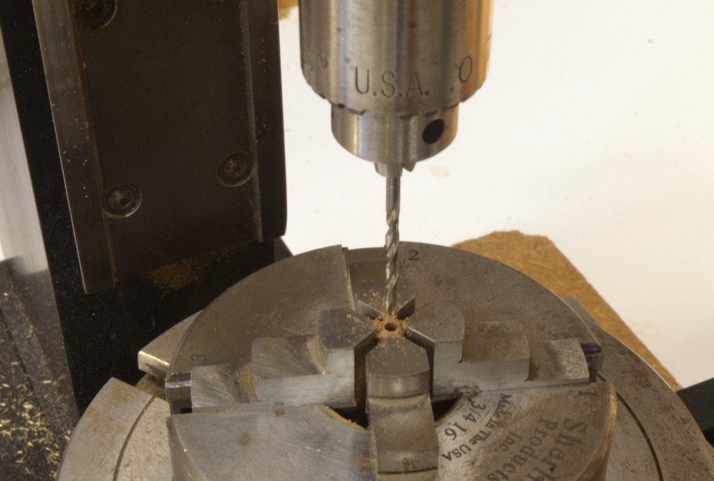
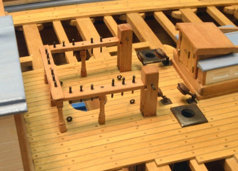
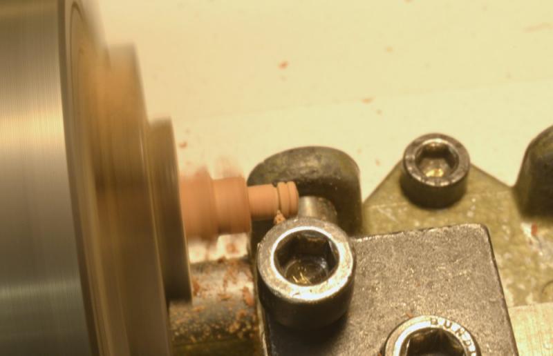
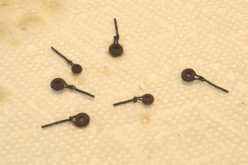
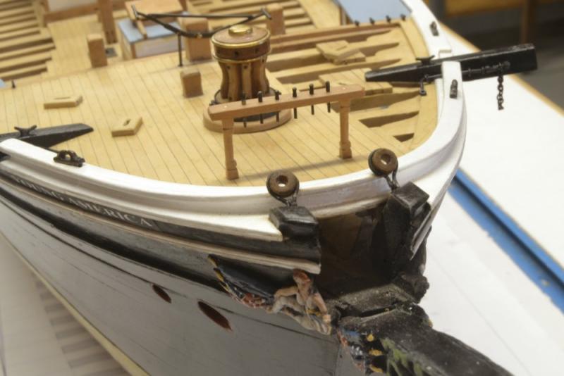
Young America - extreme clipper 1853 Part 172 – Stay Bullseyes/Eyebolts There are six "heavy duty" eyebolts with shackled bullseyes that secure the two legs of the fore, main, and main topmast stays. Those of the main mast are anchored in the deck and the forestay is secured to the knightheads. I'm including these and all deck and hull eyebolts as part of the "pre-rigging" and intend to install all those connections before starting on the masts. The process for making the bullseyes and fitting the iron shackles is very similar to that used on the channel deadeyes described earlier. The process starts with the bullseyes. There are two sizes of these bullseyes, 11" for the fore and main stays and 8" for the main topmast stay. After turning a cherry cylinder the small bullseyes were shaped in the lathe and parted off first, followed by the larger size. This allows them to be turned "overhanging" without end support and without deflection. The first picture shows one of the 11" bullseyes being turned. The edges were rounded with a file before the parting step shown in the photo. The pieces were then filed/sanded to remove stubs from the parting. They were then set up in chuck in the rotating table as described earlier for the deadeyes. The rotating table is not really required for this, but it is easy to center with a dial indicator on the center hole. I believe this was shown earlier. The center holes in the bullseyes were then drilled as shown below. I did this in the mill as described so the holes would be precisely centered. Although lathe drilling can be very convenient, sometimes (at least in my aging Unimat) it is more likely to produce off center holes, especially on the smaller pieces. In fact, for the small bullseyes I started the hole with a center drill before changing to the final small drill bit. The larger bit shown on the 11" bullseye above was stiff enough to stay on center without that time consuming step. The edges of the bores in all of the bullseyes were then rounded by twirling diamond bits by hand in a pin vise as shown below. The bullseyes were then polished up and dyed with a non-fading walnut stain made from VanDyke crystals. These will later be waxed. The next picture shows the first step in making the shackle. The shackle bolts were silver- soldered to the ends of the shackle with the eyebolts slipped on but away from the solder. These were then maneuvered over the bolt end of the shackle. The six shackles with their eyebolts are shown below. These were then slipped over the bullseyes, crimped and each whole assembly washed with liver of sulfur to blacken the copper. The blackened assemblies are shown drying on a paper towel in the next picture. The next picture shows two large bullseyes for the forestay bolted through the knightheads. These are often shown bolted into the tops of the knightheads, but this makes no sense to me because the strain could easily split open the top of the knighthead. I bolted these through the aft side just below the top. (Engineering license.) The connections for the main and main topmast stays are shown below. Iron reinforcing plates were fitted at the base of these. Location of these required some consideration (and again some license was exercised). The larger mainstay eyebolts are anchored through the deck beam. The position was plotted using a dummy lower mast and a full sized line to check for interferences with the bitts, the cabin roof, the foremast, and the anchor chain openings. The smaller main topmast stay eyebolts are likewise anchored on the deck and not to a cross member between the bitts as is often shown. I omitted this member on both fore and main masts because rigging for the double topsail rig greatly increases congestion of ropes in this area, especially in front of the mast. The location shown seemed logical, and as with the larger stay, will avoid interferences – I hope. Ed


- 3,618 replies
-
- 42
-
-
- young america
- clipper
- (and 1 more)
-
Thank you, Kevin and thanks to others for the likes. All of these cleats will have rigging lines belayed to them on the finished model, so "perfection" was not an objective - fortunately for me. The first method has the advantage of producing consistent profiles quickly - something I could not hope to achieve at that small size with the second method. Final filing and rounding does tend to produce some inconsistencies that I trust will be obscured when the lines are belayed. Ed
- 3,618 replies
-
- 9
-
-
- young america
- clipper
- (and 1 more)
-
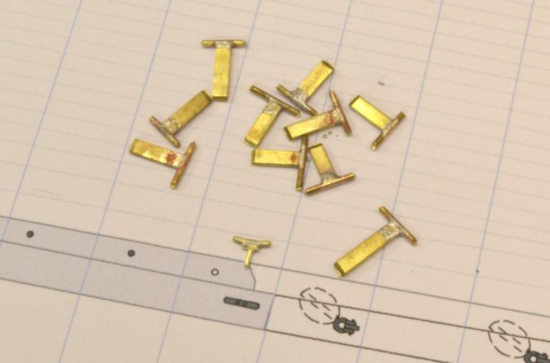
Young America - extreme clipper 1853 Part 171 – Rigging Cleats 2 There are ten larger 12" cleats. These will be used to belay the sheets and tacks for the lower sails on each mast. They could have been made by the method used on the 9" cleats described in the last part, but the larger size and the lower required number suggested a fabricated approach. One of the shaped cleats is shown in the next picture with the remaining unfinished silver-soldered fabrications. After soldering, each cleat was shaped by filing as shown in the next pictures. The hand vise shown above was helpful but most of the work was done with the piece in the vise as shown below. In this picture the single bolt is being filed to size. Nine of the required ten are shown below. The tenth sailed off to parts unknown while being buffed with the rotary tool, so another had to be made. Murphy's rule corollary: If you fail to make spares, they will later be required. The next picture shows two of these installed. Cleats on the rail like the one shown are for the tacks. Those on the deck will belay the sheets that pass through the bulwark sheaves like the one under the pin rail in the picture. The next picture shows one of these cleats mounted on each of the catheads. These will belay the fore course tacks. The eight small cleats for the jib sheets may also be seen on the breast beam in this picture. Ed

- 3,618 replies
-
- 38
-
-
- young america
- clipper
- (and 1 more)