EdT
-
Posts
2,213 -
Joined
-
Last visited
Content Type
Profiles
Forums
Gallery
Events
Everything posted by EdT
-
Rob, Webb's papers are pretty extensive, usually with offsets, lines, sail plans and his notes. I thought McKay's information was published in the 1880's. I would check the bibliography in Crothers, American Built Clipper Ship. I believe it is referenced there. I have very limited info on McKay's ships. Crothers book on mastmaking includes spar plans, #1 and #2 for Great Republic - as built and as rebuilt after the fire. Ed
- 3,618 replies
-
- 4
-

-
- young america
- clipper
- (and 1 more)
-
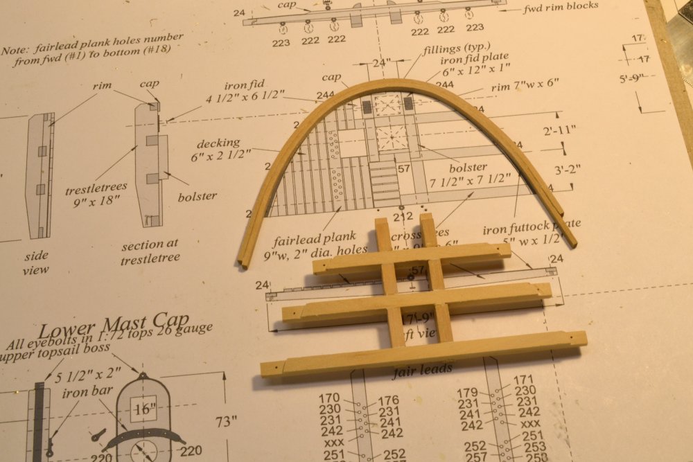
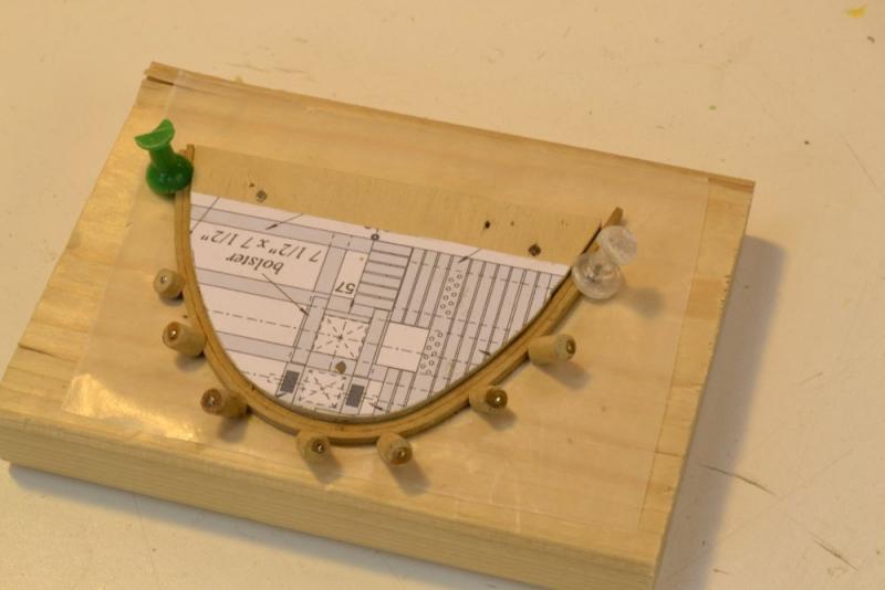
Again, thank you everyone. Rob, its really not so much a question of inaccuracy as it is of drawing status, especially when the model work is catching up with the drawing availability as it is right now. "Approved for Construction" drawings go through several phases from initial sketches to final as-built. For example, on the mast drawings, when the final shape of the mast was "approved" the drawing went into the shop for that work only, while drafting continued on the next phases - banding, hounds and bibbs, top structure, top details and rigging conections - with each going into the shop when ready for the particular work. Construction sometimes initiates revisions. If so, these get put on the drawing until the final complete "as-built" and checked revision is ready for the book. Some, usually minor, errors will escape in the 100's of drawings. As to what is known about mast and spar making on American 1850's merchant craft, it is true, as Crothers states in his book, that specific documentation is on American practice is scarce - and I am taking his word for it rather than retrace his exhaustive research steps. However, there is little to indicate that basic American practice differed from British practice - pre-Steel through the 19th Century - until steel began to replace wood. So, much of what is needed for modeling is well-founded and available. I have Webb's original spar plan and a list published independently at the time that agrees with the plan. Crothers relied on various sources for geometry - all in basic agreement - from Steel through Fincham's 1843 work. The data is there, but wading through it takes time. I spent an entire day last week confirming the way caps were made and fitted, and by the way, proving to myself that Crothers cap drawings were, in fact, quite correct. One must also remember, that on these world-circling ships, spars were lost and replaced at ports and shipyard everywhere. Hello, Allan. Yes, the rim in the photo is upside down. I started by laying out the holes on each initially oversized xtree by taking off the hole spacing on each xtree with dividers and transferring it to the centerline of each xtree timber. The shape of the curved rim was transferred to the xtree assembly from the template. The half-laps in the xtrees were then cut and the ends roughly trimmed. The curved rim was fitted to the laps and through-drilled from the holes in the xtrees. Half-laps were then cut in the rim. Pins were used to align the pieces for gluing. The process was made easy by using a laminated rim. After drying the pieces against the template after boiling, they were glued using the template. There was virtually zero springback as may be seen in the photo. Cheers, everyone. I will try to put out the second post on the tops this week. Ed
- 3,618 replies
-
- 8
-
-
- young america
- clipper
- (and 1 more)
-
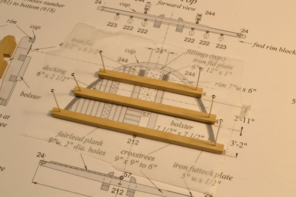
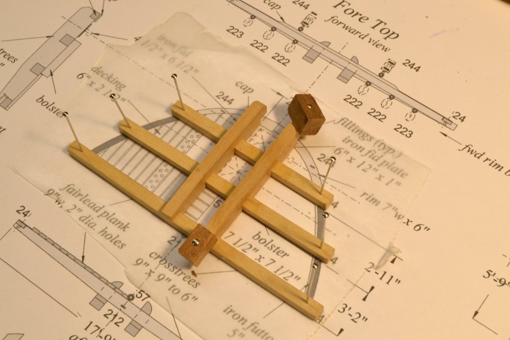
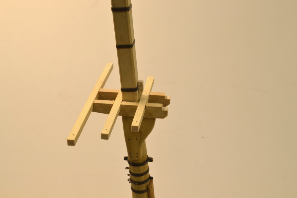
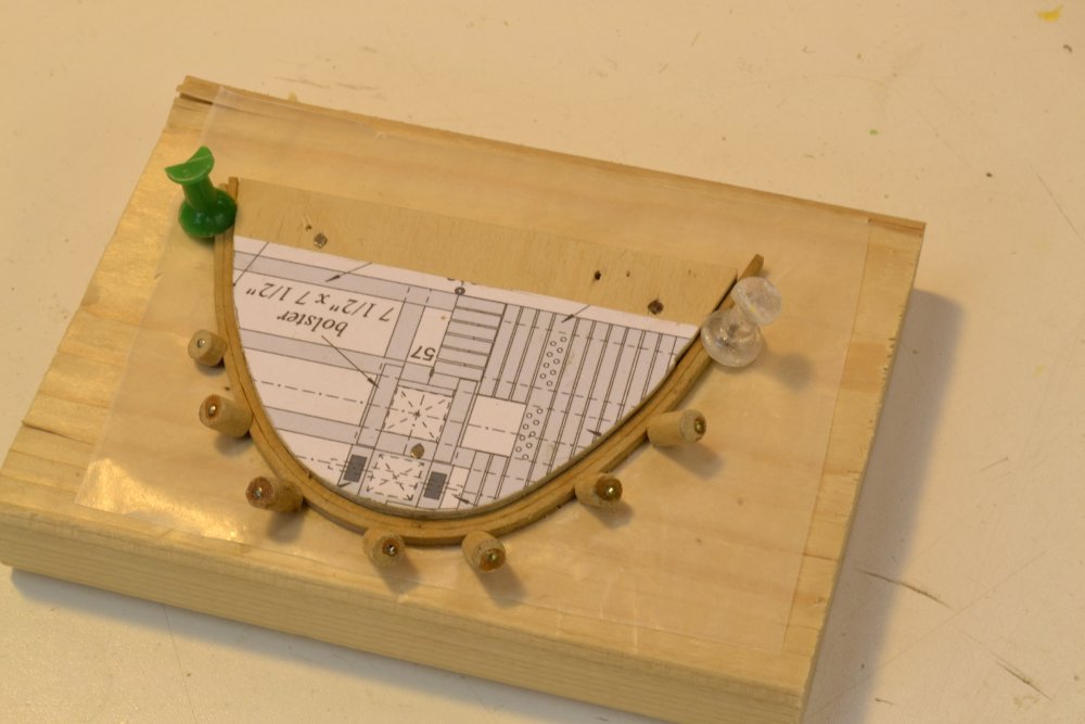
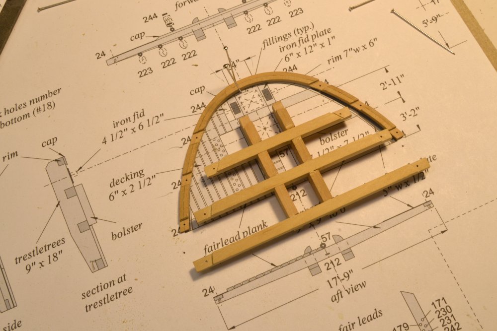
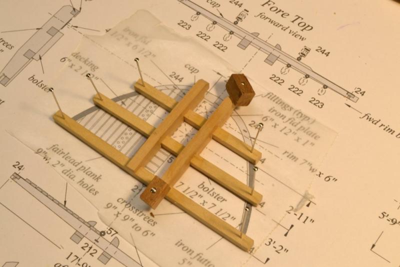
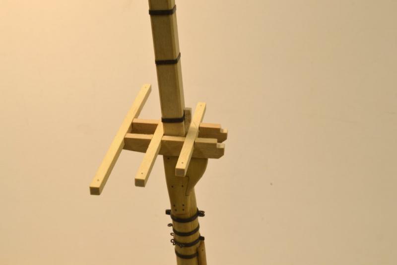
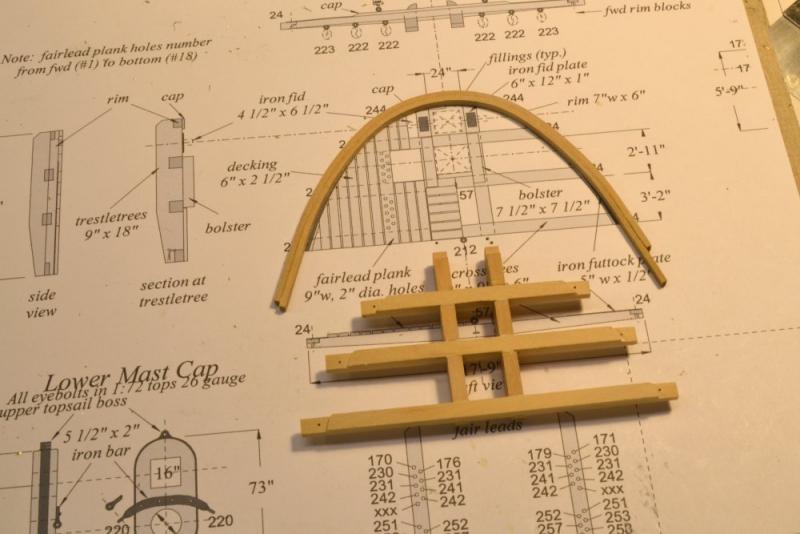
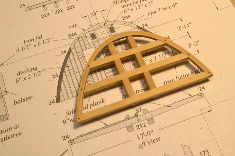
Young America - extreme clipper 1853 Part 190 – Framing the Fore Top It was nice to get back to some pure – well almost pure – woodworking on the tops. There will be ironwork involved, but not in this post. The first picture shows the first step, pinning the 9" x 9" crosstrees to the drawing. Pins were placed in holes that are centered on the slots that will pass the deadeye straps for the topmast shrouds. They are conveniently located to index the pieces. In the next picture the 9" x 18" trestletrees have been mortised and fitted. The port trestletree is being glued, held down by pin clamps. The next picture shows the basic framework positioned on the hounds. The spacing of the members provides just sufficient clearance to go over the masthead bands. The top framing is temporarily wedged forward of the mast to check and adjust the level on the top face of the hounds. The top is aft-heavy. The next picture shows the rim being formed. This was made in a two piece laminate to facilitate bending and minimize spring-back after the two dried pieces were glued. The rim is shown on the drawing in the next picture. The lap joints in the trees have been cut in this picture. In the next picture the laps have been cut in the rim. Indexing holes were drilled in the rim before the joinery was done. Finally, the assembled framing. Next, planking and triming out the top. Ed


- 3,618 replies
-
- 37
-
-
- young america
- clipper
- (and 1 more)
-
Thank you, everyone for the comments and likes. As always, I am most appreciative. Bob, as always, you are correct. I am very surprised that this is the first discrepancy to be noticed in drawings that often appear in the pictures. Perhaps its a bad habit to work atop preliminary drawings, or any drawings for that matter, but these sheets are so expendable that I often work with them on the bench. I might also add that I almost always work from unfinished versions of these. I am probably up to more than a dozen revisions - at least - to the mast detail drawings. The missing detail was added to the mizzen dwg after the photo - and the work. If you look at the first picture in the last post you will see that the stool is missing. There's no rigid sequence in this shipyard - especially when the construction is hard on the heels of the drafting - like now. I appreciate your keeping an eye on me. The fore top is just about complete. I expect a couple posts on it before Christmas. Cheers, Ed
- 3,618 replies
-
- 8
-
-
- young america
- clipper
- (and 1 more)
-
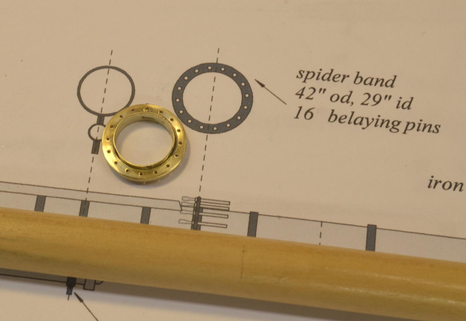
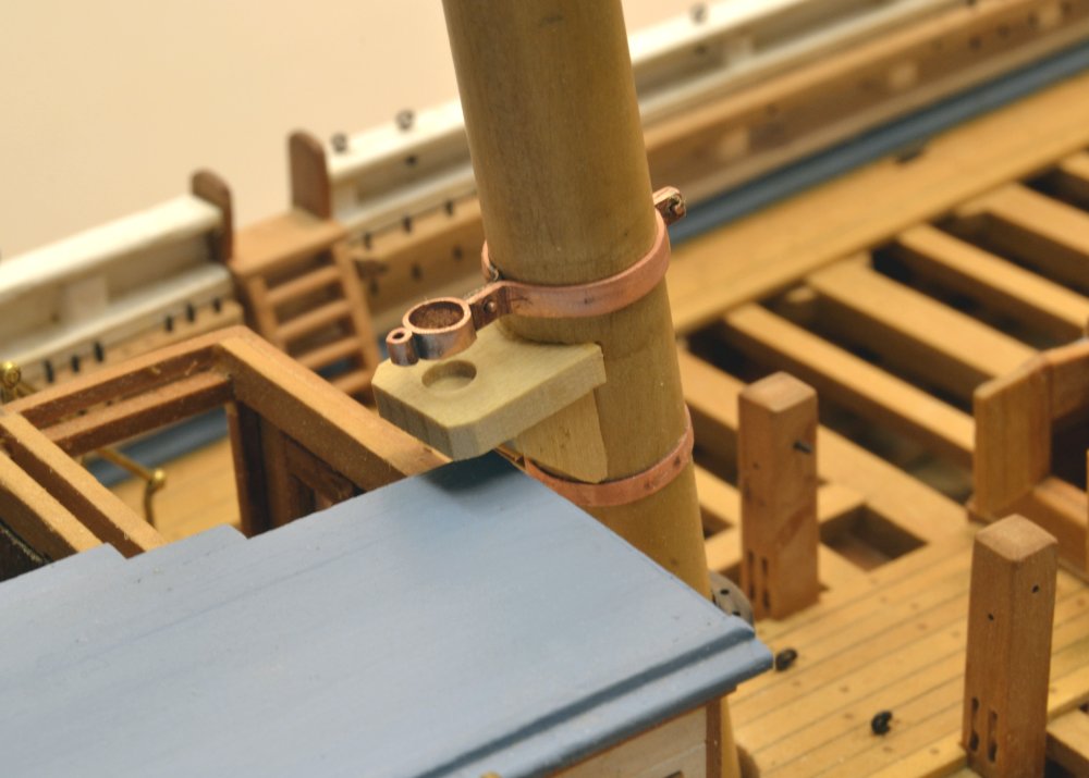
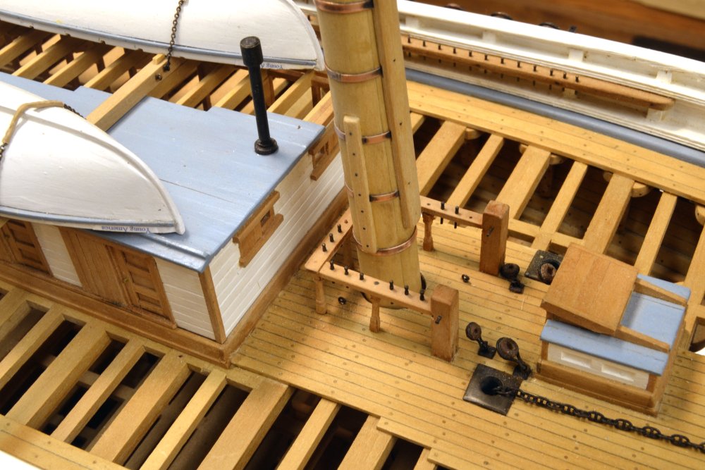
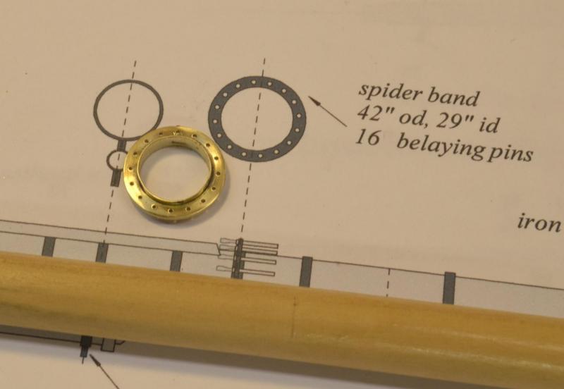
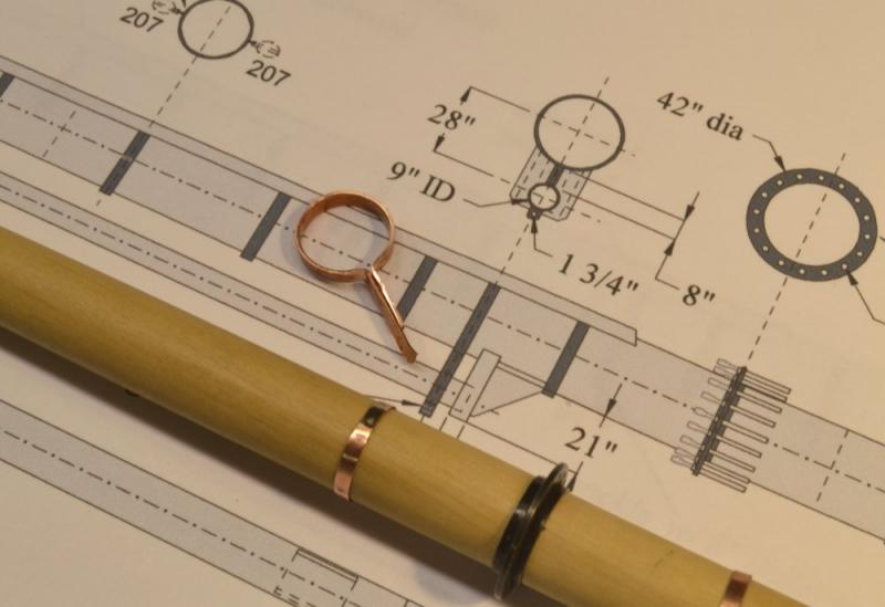
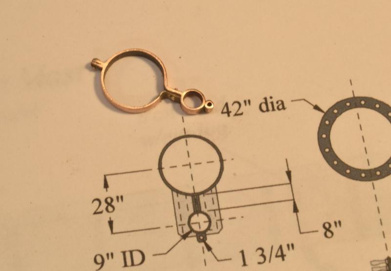
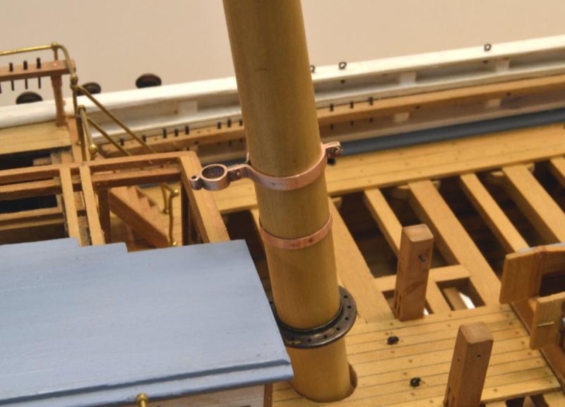
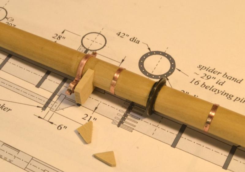
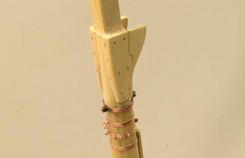
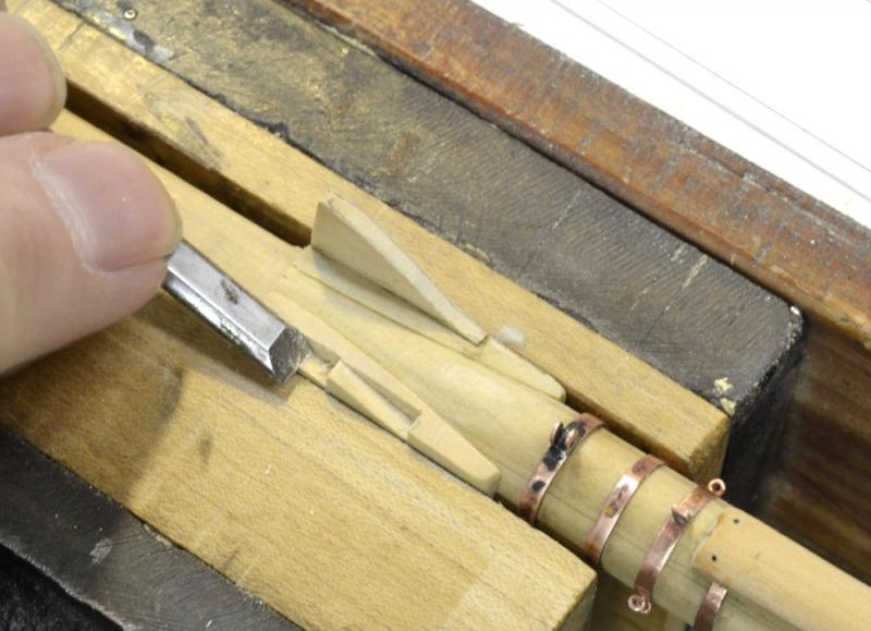
Young America - extreme clipper 1853 Part 189 – Lower Mizzen Fittings The mizzen mast has some additional hardware not found on the forward masts. First, there is a belaying ring, or spider band around the mast instead of the fife rails of the forward masts. The design of this is not documented, but from the work on the rigging list, at least 16 lines should be belayed here. The ring for the model is a simple circular flange around the mast bored for 16 belaying pins. The unblackened part is shown in the first picture. This was made as a turning from a solid brass billet to fit over a brass tube mast ring that was silver-soldered in. The pin holes were then drilled in the mill using the rotary table. The ring will be a tight fit over the mast about 39" off the deck. This is a pretty piece that will be completely hidden under a mass of rope. In the next picture it has been blackened and installed on the mast. Above it is a reinforcing hoop and above that will be a bracket that will support the spanker mast. A start on the spanker mast bracket is shown in the drawing. The mast band part of it has been shaped to fit the mast and will be soldered with other parts added progressively. The finished bracket is shown in the next picture. This piece is of thicker stock than the normal mast hoop, as were the bands for the lower yard trusses. The small eye will support the goose neck of the spanker boom. Both pieces are shown on the mast in the next picture. The spider ring was pre-blackened, but all the copper work will be blackened later as was done for the other masts. The third piece to be made was the wood stool for the spanker mast. While the bracket maintains the horizontal position, the stool will take the weight of the 9" diameter mast. The next picture shows the stool parts. For strength on the model, I set the stool itself into a mortise in the mast that will give it the appearance of a surrounding piece but the strength of the mortise joint. Two triangular gussets that will reinforce the stool are shown. The last picture shows the three items installed. Shaping and polishing of the stool assembly has yet to be done. The gussets were glued to flats filed on the mast. The remaining hoops may now be installed on the mizzen mast. Meanwhile, work has begun on the fore top. Ed

- 3,618 replies
-
- 42
-
-
- young america
- clipper
- (and 1 more)
-
ancre La Salamandre by tadheus - 1:24
EdT replied to tadheus's topic in - Build logs for subjects built 1751 - 1800
I have been catching up on your build, Pawel. Lovely work. I love the bronze sheen on the guns against the woodwork. Ed -
Thanks everyone for the comments and likes. Thanks for the comment on the mast detail, Frank. t has taken some time and some rework to get a good result between the clean soft yellow of the wood and the smudgy black copper, but I am reasonably happy. The mast detailing has been slow because virtually all the rigging detail must be known so the various fittings can be installed at this stage. A lot of back and forth between the shop and the drafting. Yes, Allan. What can we do about these infernal "lay people" who wonder how the water was kept out of these open framed ships? I guess we should be thankful for the "teachable moments" many comments provide. A little humor helps. I once told someone that large ballons were deployed in the hold. We are a strange and not too common breed. Ed
- 3,618 replies
-
- 8
-
-
- young america
- clipper
- (and 1 more)
-
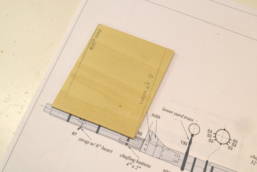
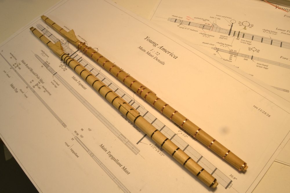
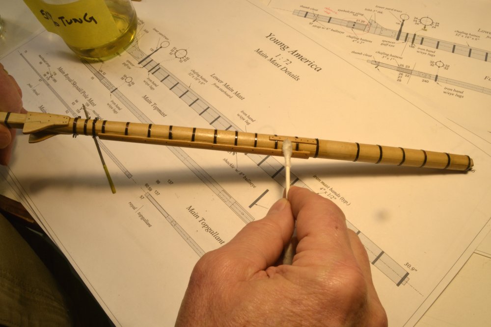
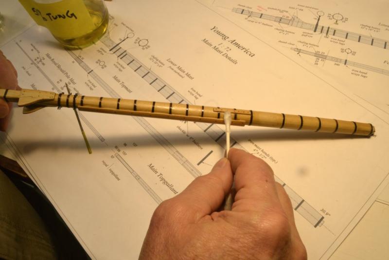
Young America - extreme clipper 1853 Part 188 – Completing Main and Fore Masts Just a few finishing up steps were required to complete the two large lower masts. First, the tops of the hounds had to be angled to the rake of their masts so the tops, when fitted, would be level. The foremast rake is about 4.75 degrees and the main is at about 5.4 degrees. A plywood gauge, shown in the first picture was trimmed on each side to these angles. This gauge was then used to check the angle of the hounds as it was trimmed back by filing, as shown below. The gauge is held parallel to the masthead in the picture. These mastheads are not tapered. Both sides had to be matched. These will get a final trim when the tops are installed and can be levelled more accurately and in both directions. The next picture shows the main and fore masts with all the construction work completed. All the foremast ironwork has been blackened in the picture. This was all done all at once after all the bands, including the masthead bands were installed and all other work on the mast completed. This was done to avoid excessive handling of the blackened bands. Liver of sulfur solution was brushed into each band until black. Brushing helps eliminate black powdery buildup. As each band was blackened it was rinsed under running water. The masts were left to dry overnight then given a finish of Tung oil diluted 50%, applied with cotton swabs. In the next picture a dry cotton swab is being used to soak up any excess oil. The Tung oil restores the tone of the Castello and protects the blackened metal as well as the wood. The mastheads were left unfinished so that wood fittings may be added later after the tops are slipped over. The last picture shows the two masts placed temporarily in position to allow the Tung oil to dry.. Mast wedges will be made and fitted at the partners later, probably after the tops and masthead trim is installed. This will permit that work to be completed on the workbench. Meanwhile, the mizzen mast is in the works. Ed


- 3,618 replies
-
- 43
-
-
- young america
- clipper
- (and 1 more)
-
Thank you Albert and Rob and thanks everyone for the likes. Welcome back, Guy, and thanks for your comment. Ed
- 3,618 replies
-
- 2
-
-
- young america
- clipper
- (and 1 more)
-
Wow. Lots to look at in that last post. Great work, Frank. Ed
- 649 replies
-
- 6
-
-
- dunbrody
- famine ship
- (and 2 more)
-
Tony, The tables of contents in both Volume I and II are somewhat abbreviated. I have attached more detailed versions that I prepared before final publication. However, with very few exceptions, these reflect the content of the books, by sub-chapter headings. I hope these will be helpful. Thanks for your interest in the books. Ed Naiad Vol I Contents.pdf Naiad Vol II Contents.pdf
-
HMS Naiad 1797 by albert - FINISHED - 1/48
EdT replied to albert's topic in - Build logs for subjects built 1751 - 1800
Bravo - again and again, Alberto. Ed -
Maury, if you can get your hands on it, Steels Elements of Mastmaking, Sailmaking and Rigging has the proportions of spars based on length, p. 49. I won't copy it, but if you give me the spar list - I assume not too many - I will be glad to give you the proportions. Crothers on Mastmaking also has the proportions. Although the book covers a later period, the proportions did not change much and if I recall Crothers included Steel's proportions. Ed
- 525 replies
-
- 1
-
-
- anchor hoy
- hoy
- (and 1 more)
-
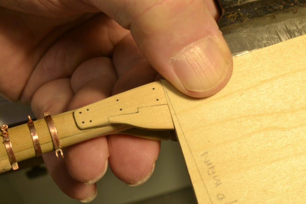
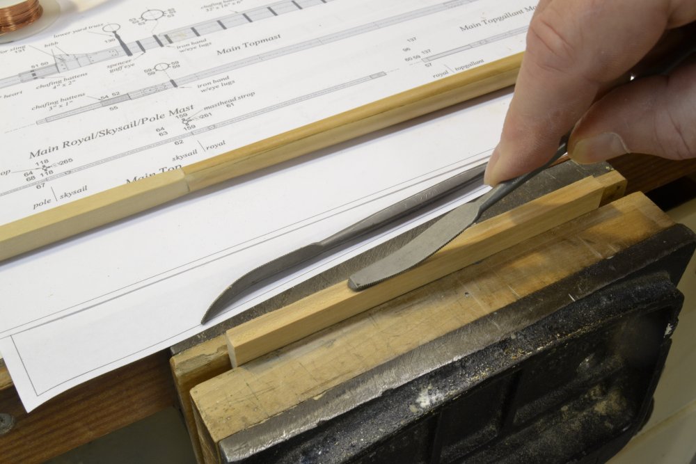
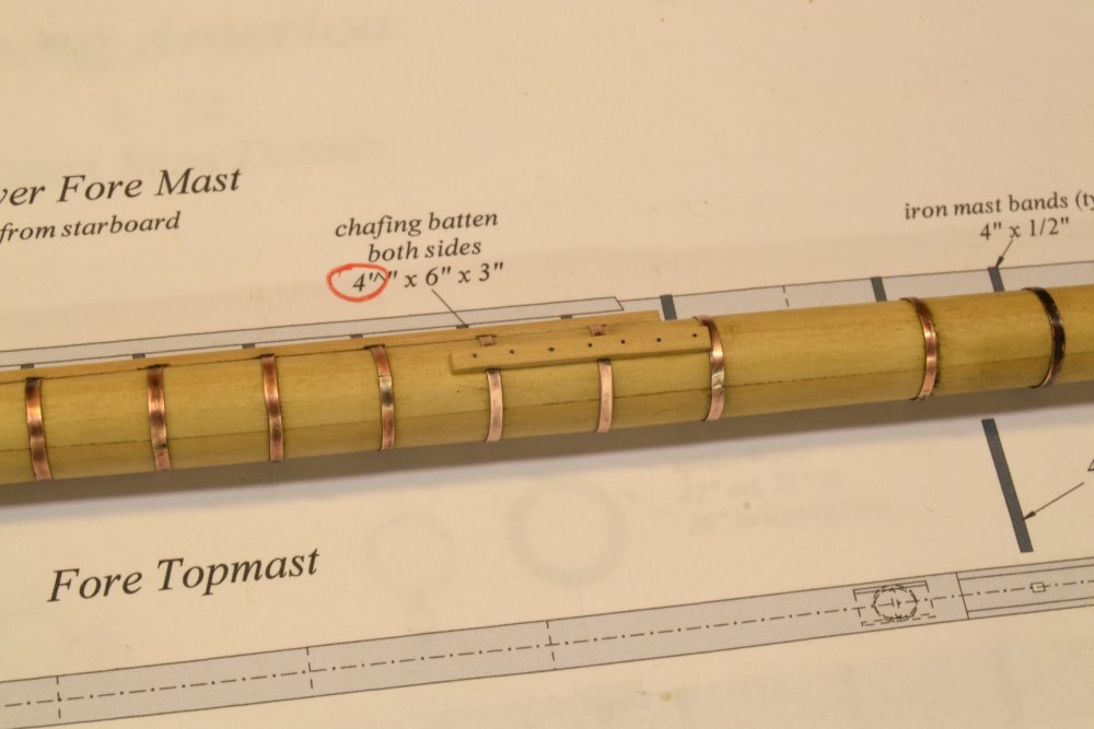
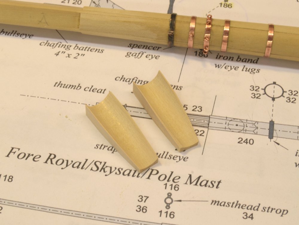
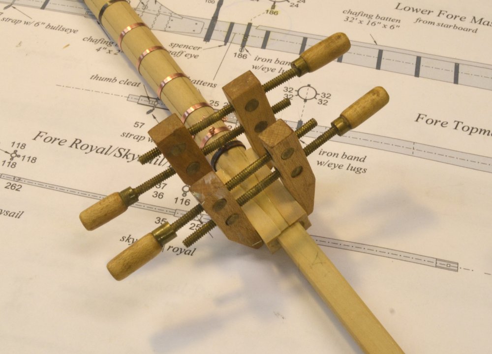
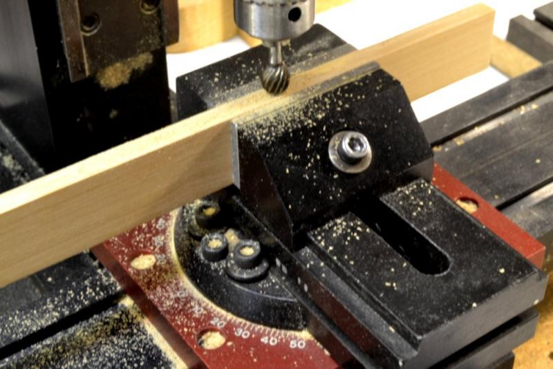
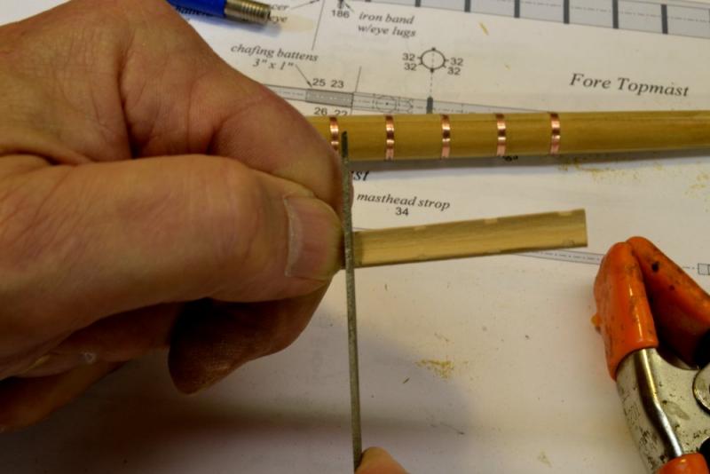
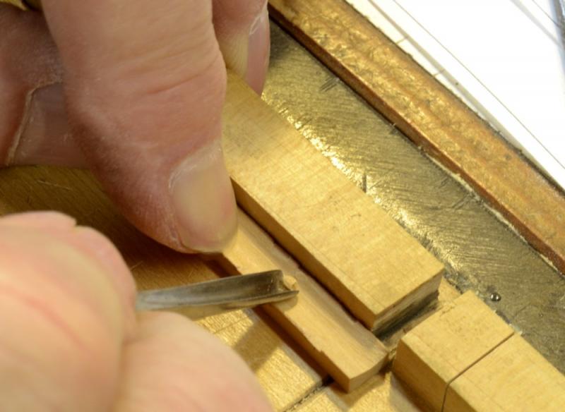
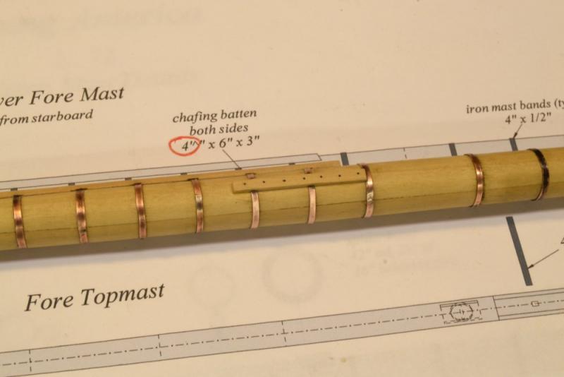
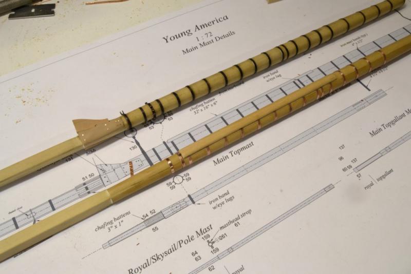
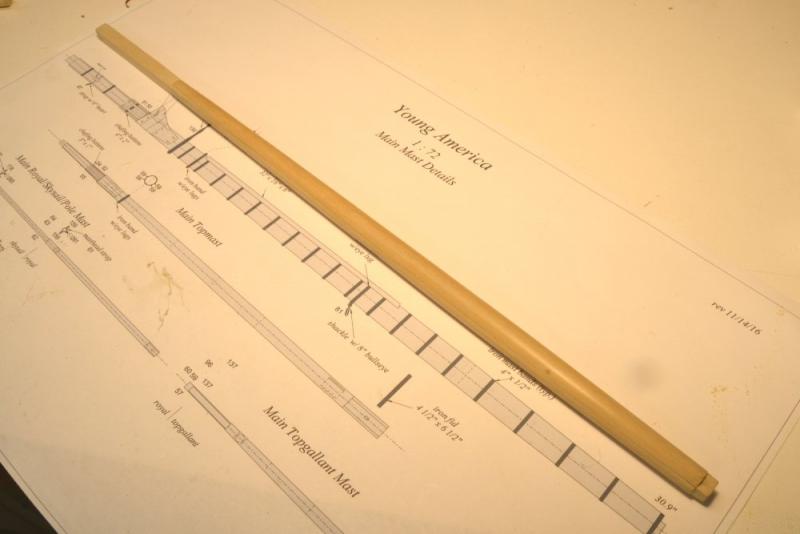
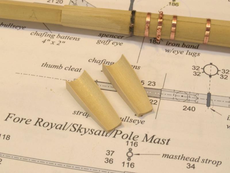
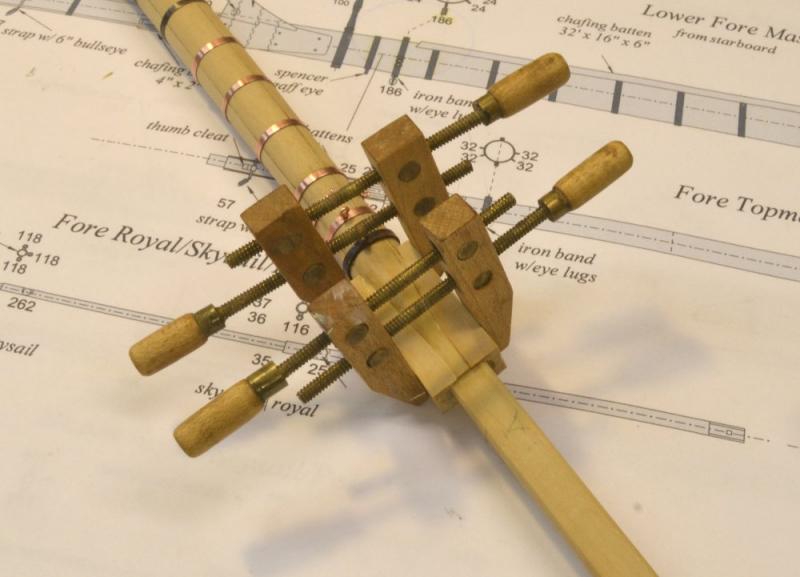
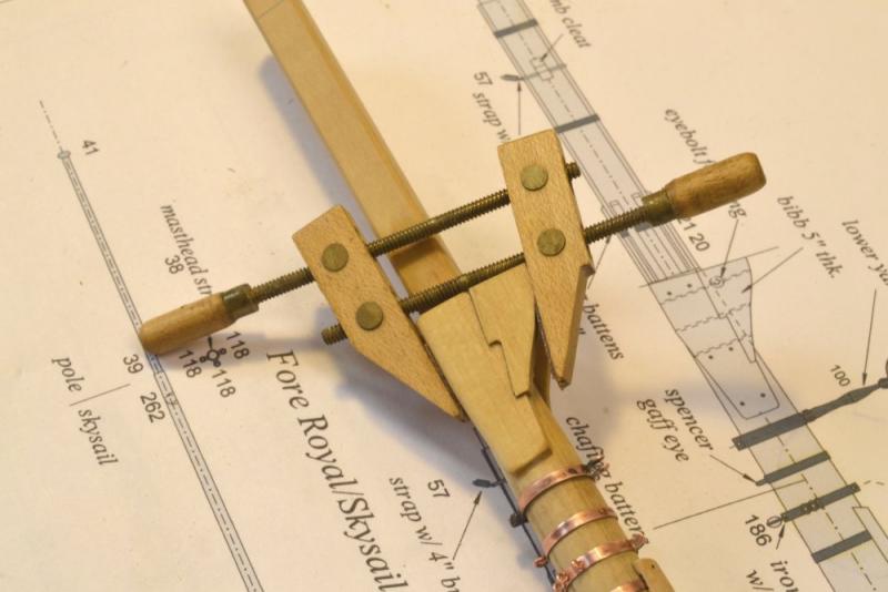
Young America - extreme clipper 1853 Part 187 – Chafing Battens Chafing battens were used to limit damage to sails and rigging that were subject to rubbing against ironwork or other rough parts of masts or spars. The largest and most prominent of these are the large forward battens on the lower masts. These protected the lower sails. I am not sure how these battens were fitted over the mast bands in practice, but I assume they would be slotted, caulked, and sealed to prevent moisture causing rot on the mast. So, fitting these neatly over the mast bands becomes a chore. First, the battens must be fit over the mast. I started by milling a concave gutter in the batten stock as shown in the first picture. The purpose of this was to establish a straight groove as a starting point for the handwork necessary to fit the piece to the tapered mast. This fitting was done with the curved rifflers in the next picture – with frequent checks against the mast itself, in this case the unbanded, new main mast in the picture. After fitting to the mast, the batten was ripped off of the stock shown above. Once the bands were placed on the mast, clearance slots were filed at the band locations. These slots provide clearance at the edges but not in the center of the batten. The slots are shallow. The bands are only .010" thick. The spaces between the slots were hollowed out with a small gouge to help the batten lie flat on the mast. Since these inside hollows will not be visible, no attempt was made to square them to fit the bands. The batten was then glued to the mast. The shellac coating was filed away under the joint so the glue would adhere. The batten was then nailed/bolted along its length with monofilament bolts held with CA. The batten was then rounded on its forward face to the correct thickness. The next picture shows the forward batten and the smaller side battens glued and bolted to the foremast. The side battens extend over the area where both the mainstay and the main topmast stay pass beside the mast. This was checked by running lines from the main top, hence the red correction notation on the drawing. The next picture shows these with the foremast temporarily in position. The last picture shows the forward batten on the new main mast – alongside the replaced earlier mast. Ed


- 3,618 replies
-
- 32
-
-
- young america
- clipper
- (and 1 more)
-
I like your idea on the resin cast glazing. Look forward the the fianl result. Bravo. Ed
-
GAW, my amazement and speechless state continue with each new post. If I may make a suggestion on the pictures. I think there is value to interspersing them in the text, especially when they are lengthy descriptions/explanations describing each. After loading the pictures in the "More Reply Options" frame, place the cursor in the text where you wish to add a picture, then click on "Add to Post" in the box at the lower left. This will place that picture at the cursor location. Repeat for the others then check the placement in the Preview screen. Hope this helps. Ed
- 281 replies
-
- 3
-
-
- falls of clyde
- tanker
- (and 2 more)
-
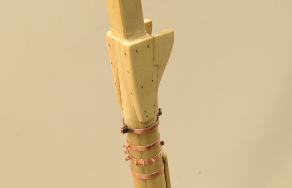
Young America - extreme clipper 1853 Part 186 – Cheeks/Hounds and Bibbs I mentioned in the last post that I was replacing the first main mast that was shown in some earlier photos. Here is the replacement ready for banding. The first mainmast was developmental as far as method is concerned, the second my main process example photo subject, and the mizzen will be the final proof of practice. In the meantime I have been pushing ahead with the foremast in the hope that it will measure up and be usable. If not I'll have another practice subject. With the foremast fully banded, other features are being added. The terms "hounds" and "cheeks" seem to be used interchangeably in my sources to describe the squared sections that supported the cross trees of the top. The bibbs are the forward extensions of these, knees if you will, that support the forward end of the top. The first picture shows these installed on the foremast, before describing the steps. The supporting upper surface will be angled and flattened later to support the top in a horizontal position on the raked mast. If my simplified five piece model design for a made mast had its benefits, the price for that was paid in the shaping of the hound pieces. In practice these were fayed usually against flats on the central spindle and extended above the hounds as part of the mast head, or doubling. Since my spindle was made the size of the head and the mast below shaped round, the side hounds had to be fitted to the round tapered mast. The two pieces are shown below during fitting. To make these, a hole was bored through a block of wood that was then tapered around the bore and separated into two pieces. The bores were then enlarged by filing/sanding to match the taper of the round mast. In the next picture these are being glued to the mast. The next picture shows the port bibb installed and the joint for the other being pared. Both joints were cut first on the hounds and the bibbs cut to fit, with some adjustments to the hounds during the process as shown. The next picture shows that bib being glued After gluing, the sides were filed flat and the bolts added. There are three through the edges of each bibb and eight securing the hounds to the mast. These are black monofilament secured with CA. Bands are sometimes shown around the lower end of the hounds. I don't see how heat shrunk bands could possibly have been fitted with the hounds in place or what purpose they would serve vs. bolts. I suppose shaped bands could be slid on before the hounds were installed then driven up over the bottom ends. On the other hand, such bands under the hounds could be fitted and of benefit. I'll save this question for the next model. Next, the chafing battens. Ed
- 3,618 replies
-
- 33
-
-
- young america
- clipper
- (and 1 more)
-
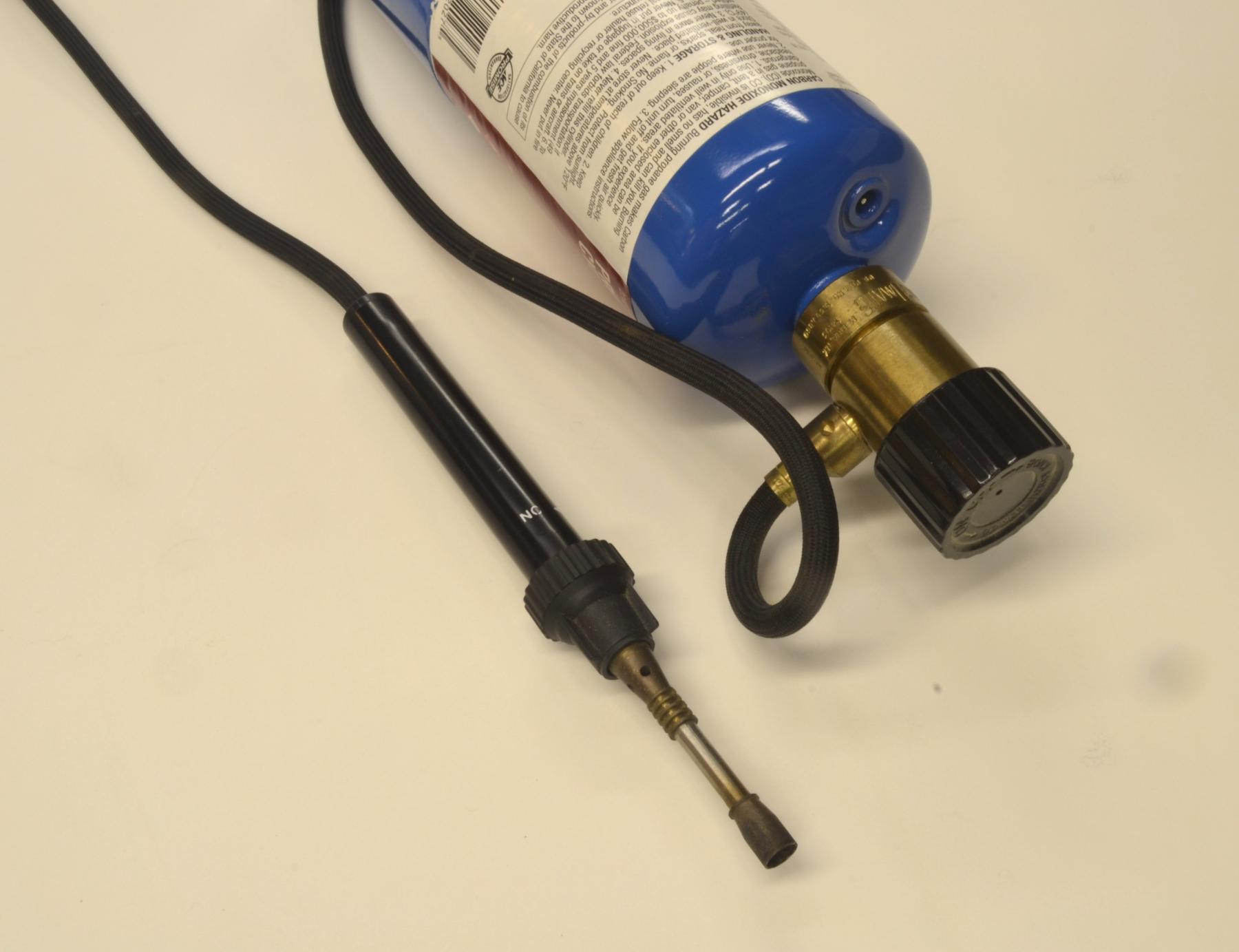
Thanks again, everyone. Rob, that is an interesting rule of thumb, suggesting that more bands are required on smaller masts. I would have to think about that. Actually, I have thought about it but to no avail.. Perhaps someone could comment? You wouldn't happen to have a reference? Jeff, I was afraid someone would ask your question. I bought the torch many years ago and have never seen one like it again. I have looked - usually after someone asks about it. Most of the small torches I have seen lately have their own small fuel cyclinder and I have no doubt they work fine. Some are self igniting. That would be a plus. I use a Bic lighter. David B, one other thought on the problem you raised. If you are using berylium copper, which I have seen sold online, that melts much lower, I believe actually below the solder temp. Ed
- 3,618 replies
-
- 4
-
-
- young america
- clipper
- (and 1 more)
-
David, the silver solder I use melts at about 1325 deg F, copper, I believe, at around 2000 deg F, so it would seem that you are overheating, perhaps too large a torch. My mast bands are .010" thick by .0625 wide and about an inch in circumference. It only takes a moment with my small propane torch to flux the solder. I have not melted one yet. A large plumbers torch or even a micro oxy-assisted torch would probably blow right through these. Here is a picture of my torch: Ed

- 3,618 replies
-
- 16
-
-
- young america
- clipper
- (and 1 more)
-
Thank you, Micheal. I appreciate your comments. 1:72 is a small scale. I see the difference in what can be done even between this model and the 1:60 Naiad, which now seems large to me. I noticed the effect to an even greater degree when building the 1;96 YA hull. So, there is always a tension between absolute reality at what is achievable at a given scale. There is also the question of perception of reality and absolute duplication, or the attempt at it. There is often a deterioration in proportionality when trying to impart too much detail to a small part. We all wrestle with these issues. Then, when rigging is involved, the issue of strength becomes very important. Finally, we all have to deal with our own limitations - our eyes, our steadiness of hand, lack of patience, and, of course, our skills that are moderated by these other things, especially as we age. Ed
- 3,618 replies
-
- 7
-
-
- young america
- clipper
- (and 1 more)
-
By the way, Frank, I should have mentioned in the last reply that in the photo of YA at San Francisco, you can actually count the main mast bands. I had forgotten that I had checked that when I was making the mast drawing because Crothers showed 4 foot spacing on his Seagull Plans (ca 1973) and states "about 3 feet" in his last book. The picture was his main reference. My guess is that they were somewhere in between. Since these were driven on to refusal while heated, I would expect some variation. For example, in January the rings might cool faster and not go as far as in say August - many variables. Ed
- 3,618 replies
-
- 7
-
-
- young america
- clipper
- (and 1 more)
-
Wonderful work, Nils. The scope and detail of this project amazes me. Ed
- 2,625 replies
-
- 5
-
-
- kaiser wilhelm der grosse
- passenger steamer
- (and 1 more)