
HOLIDAY DONATION DRIVE - SUPPORT MSW - DO YOUR PART TO KEEP THIS GREAT FORUM GOING! (Only 75 donations so far out of 49,000 members - C'mon guys!)
×


EdT
-
Posts
2,214 -
Joined
-
Last visited
Content Type
Profiles
Forums
Gallery
Events
Everything posted by EdT
-
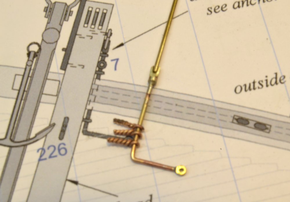
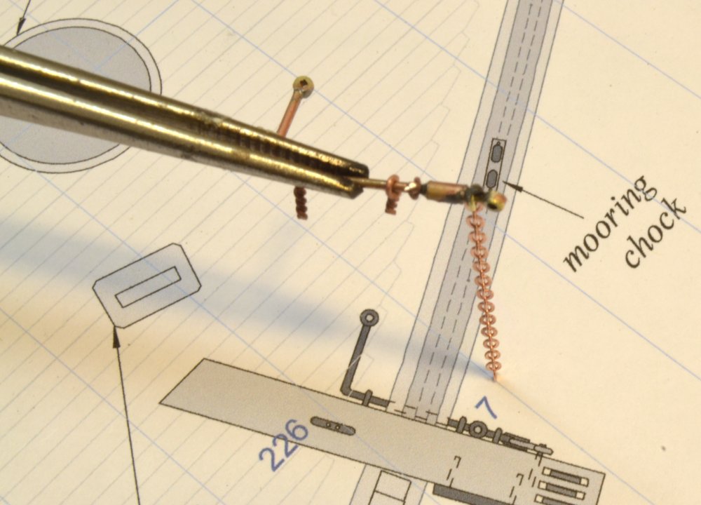
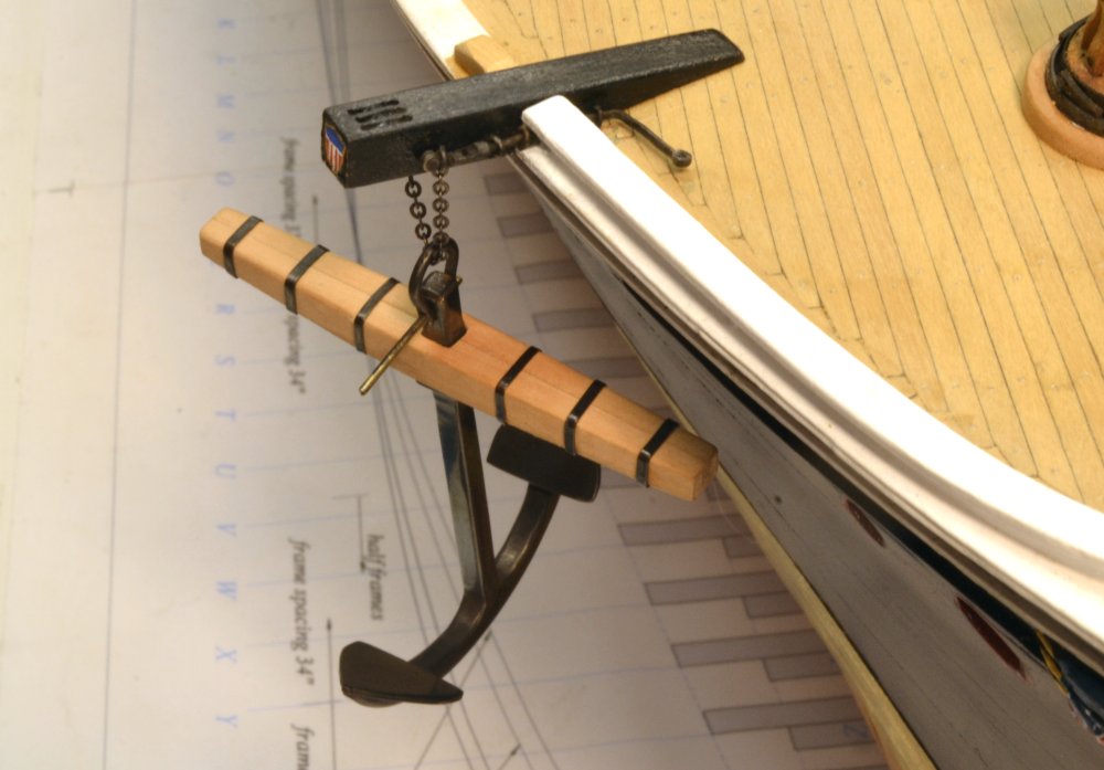
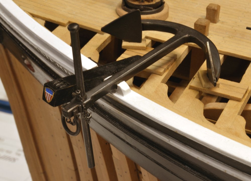
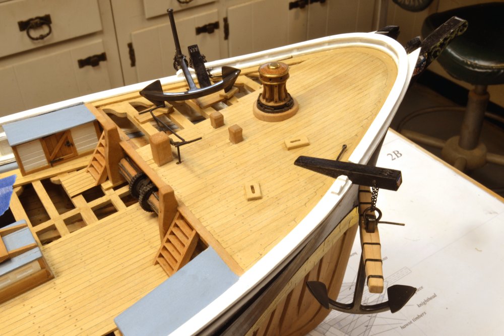
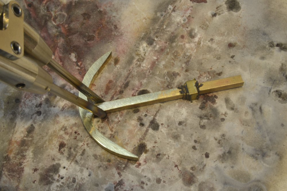
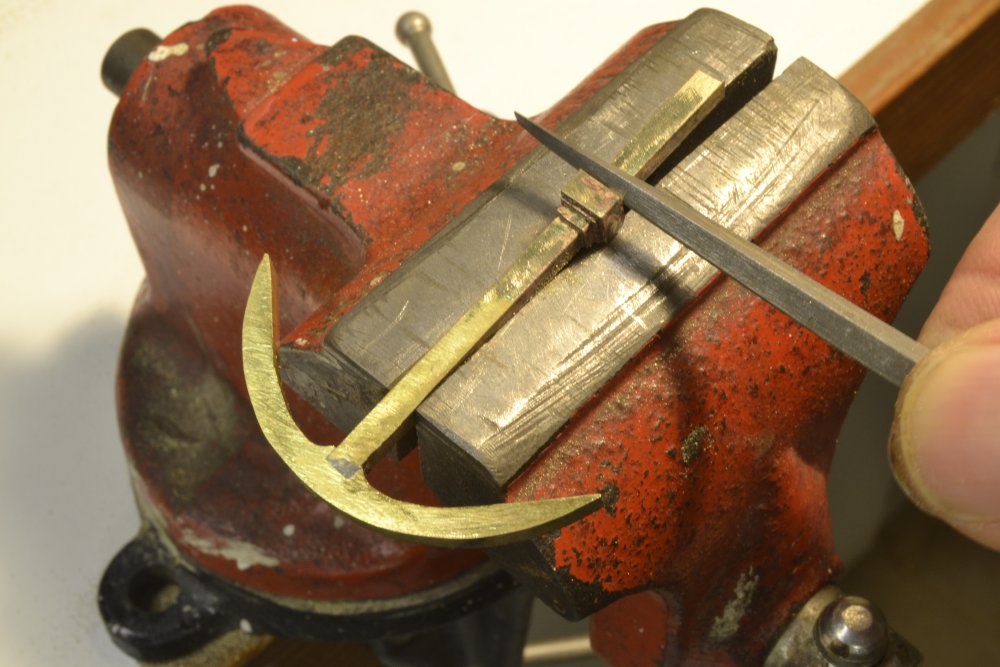
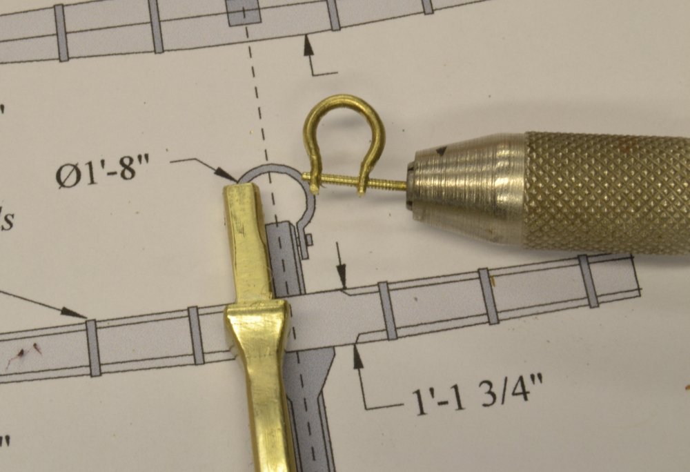
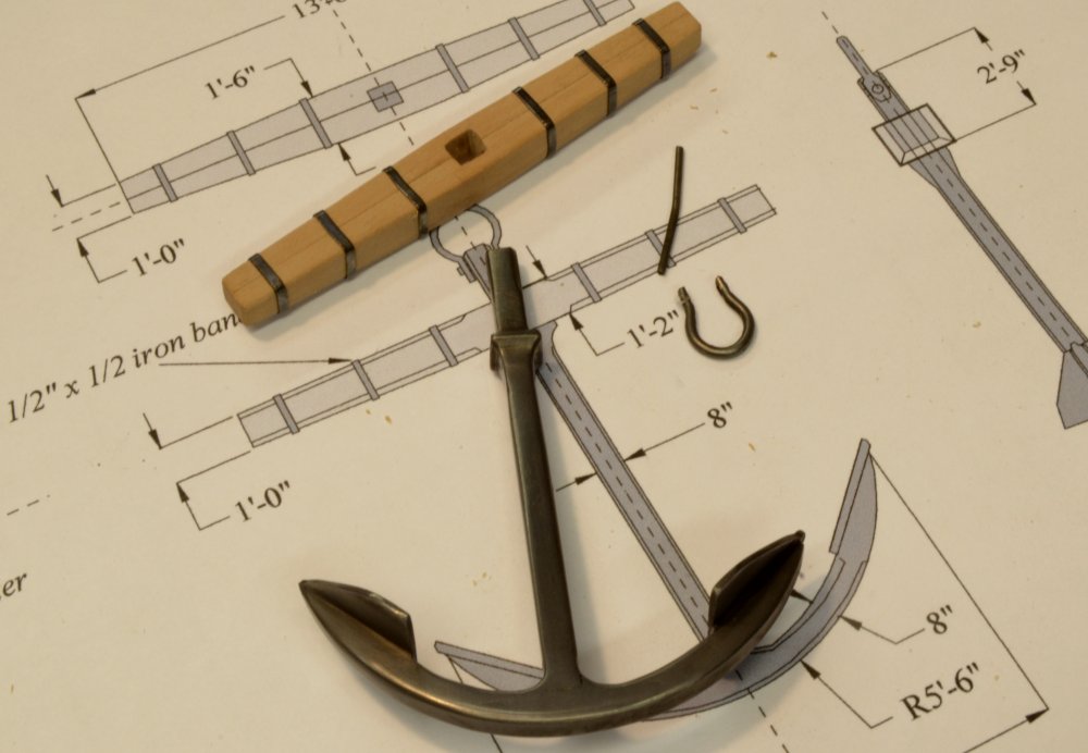
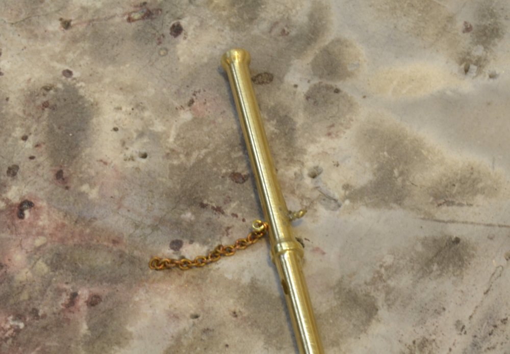
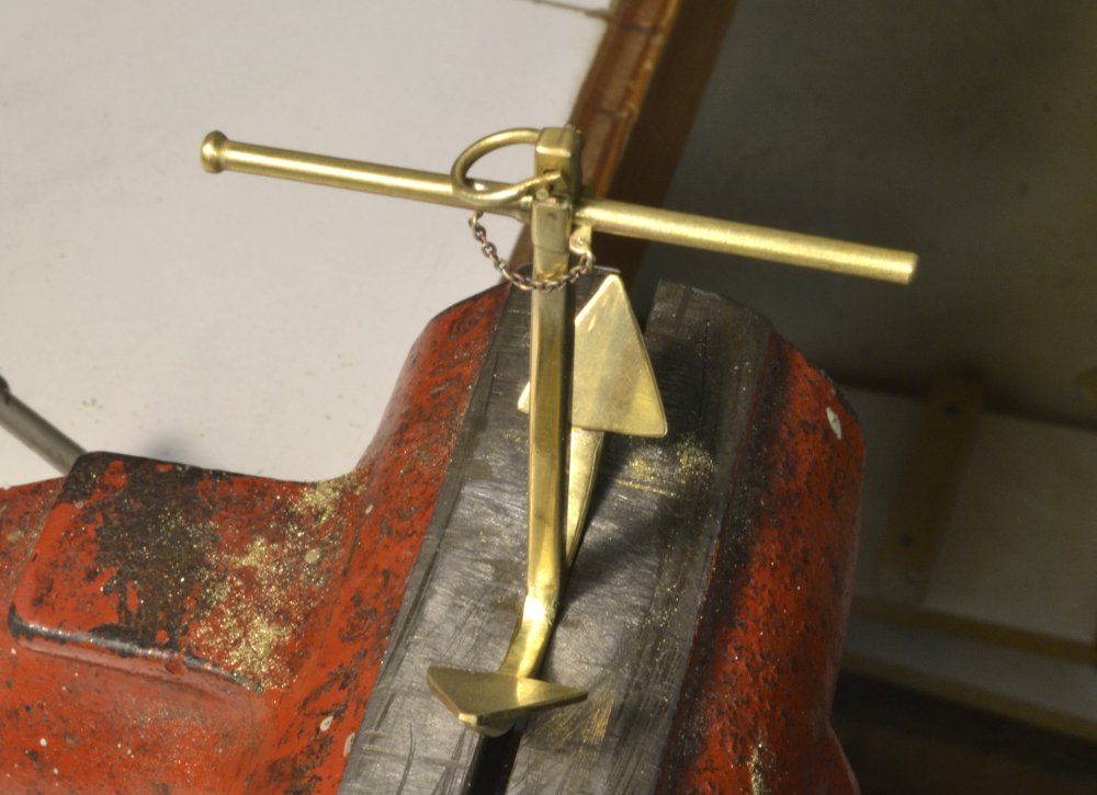
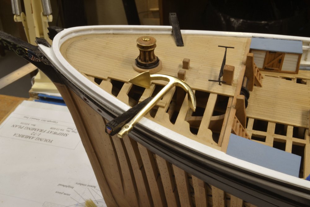
Young America - extreme clipper 1853 Part 164 – Anchor Release Gear/Mounting Like many specific details, the gear used to release Young America’s anchors is not known. However, I wanted to include it in the model since it does seem to be a pretty important part of the gear. The type used is typical of the period and is shown in the first picture. George Campbell’s work, China Tea Clippers, is a great source of deck detail for ships of the period and was the source for the design of anchor release gear used. The gear consists of a levered arm that has a spoon-like half cylinder at its outboard end. In the normal position this device supports a pin from which one end of a short chain is suspended. The other end of this chain is bolted to the opposite side of the cathead. When the anchor is suspended before release, this chain holds the anchor’s main shackle which at this stage would be secured to the anchor chain cable. To release the anchor, the lever inside the bulkhead is raised, allowing the pin at the end to fall free, releasing the short chain and the anchor. The next picture shows the lever with the tubular support at the end soldered on. Another rod for the release pin has been positioned on the end of the lever. On the model it will be soldered in place, cut off, and a bolt eye soldered to it. The three eyebolts that hold the lever to the cathead were threaded on to the shaft before any soldering. The next picture shows the short length of chain with a shackle about to be soldered to the release pin. Obviously this will not be a working model. The next picture shows the assembly in position so holes for the eyebolts and the pin bolt can be spotted. An opening was cut under the topgallant rail to just pass the inboard end of the lever and the inside eyebolt. The next picture shows the assembly blackened, installed and temporarily suspending the wooden stock bower anchor. The next picture shows the iron bar stock anchor blackened and placed on its eventual resting place on the other side – again temporarily. Three wood chocks were installed to support each anchor in their stored positions. These can be seen in the last picture. Eyebolts with restraining lashings will eventually be fitted to each of the chocks, but that will await final installation along with the chain that will be run over the winch and out the hawse hole on the starboard side. For now the anchors will go into storage. Ed


- 3,618 replies
-
- 44
-

-
- young america
- clipper
- (and 1 more)
-
HMS Naiad 1797 by albert - FINISHED - 1/48
EdT replied to albert's topic in - Build logs for subjects built 1751 - 1800
It just keeps getting better, Albert! Beautiful work. Ed -
Outstanding and lovely work, Frank. I will be interested to see how your lighter version of the clamps work out. I often had to put a lot of stress on these, but better preforming of the planks - especially the curved, twisted, heavy ceiling planks - may alleviate this. Of course, with only the mid-section to worry about, you will avoid many of the problems found at the curved ends of the hull. I used 6d nails instead of toothpicks. If you do that I recommend coating them first (I used shellac) to avoid staining the wood if you wash glue off with water. Ed
- 649 replies
-
- 8
-
-
- dunbrody
- famine ship
- (and 2 more)
-
Thank you all very much for all these comments, questions, and likes. Let me respond to some: Bob, the wooden stock is made in two pieces. Richard is correct. The two sides were usually fitted over a boss on the shaft that kept it is place, even in the occasional presence of a boss below the stock as I have shown. The two pieces were cut so there would be a gap toward the center, allowing the iron bands that were shrunk on to tighten the grip on the shaft. There were many styles of stocks used in the "non-standard" early period of American merchant sail. The copper bands were blackened after pressing into place on the stock. The stock was finish sanded first. I have found that liver of sulfur solution has no effect on surrounding wood - unless there are metal filings or dust on the wood. LOS quickly neutralizes to an inert white slurry, so there is no active material left on the wood, as there would be with the blue selenium salt solutions used on brass. Rinsing the LOS solution as soon as blackening is achieved is a precaution. This is the reason I use copper for many parts. LOS does not blacken brass. All the iron knees on Naiad were blackened after being installed and the wood is still clean. Rinsing was not very practical for these. I emphasize that the wood needs to be free of metal dust, one reason to use a sacrificial forming piece for shaping and and polishing of the bands - another is razor blade cuts into the wood. The red hue in the photo appears to be from the effect of the lighting on the photo. It appears quite black "in person." Thank you, Frank. I use the TIVA solution for degreasing after pickling - rather than solvents. TIVA is a commercial product for cleaning metal before treating. It is normally used in ultrasonic tanks, but seems to work well as a room temperature dip. I am increasingly convinced that the most important step in blackening is pickling of soldered parts, followed by polishing the metal surface. I usually drop the still-hot, soldered pieces into Sparex solution after each joint to knock off most of the oxidation and flux. Lately, after completion of all soldering, I have been immersing the parts in white vinegar, bringing it to a boil (as in food pickling) then letting it cool for a few hours before final polishing. This has worked well. Thanks, Druxey. If I can add a good idea to your repertoire, I am indeed flattered. The .005" copper cut easily with a razor blade or a surgical scalpel. I am anxious to try it on the thicker material that will be used on the many yard and mast bands that await. I may use a turned, slightly tapered, metal mandrel for those. We'll see. Ed
- 3,618 replies
-
- 12
-
-
- young america
- clipper
- (and 1 more)
-
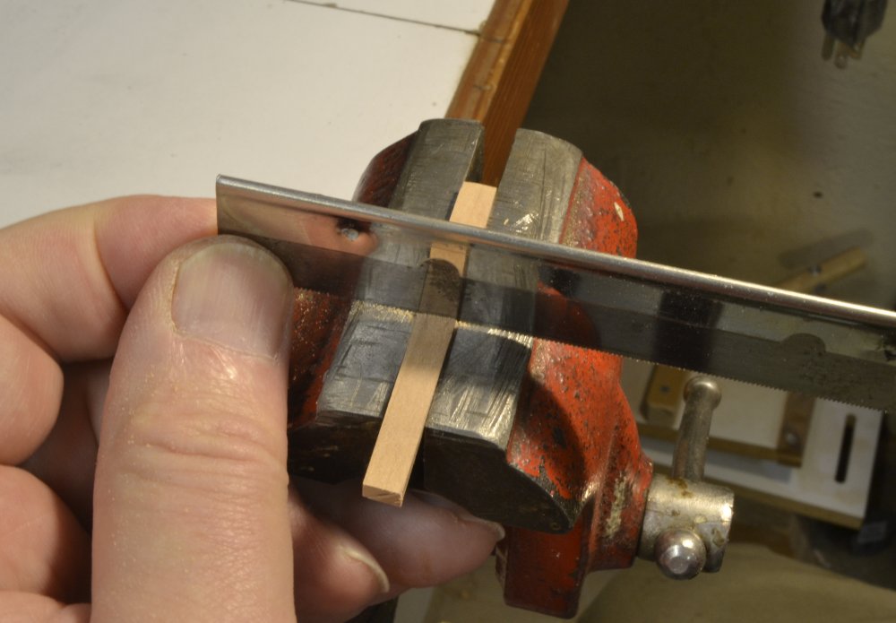
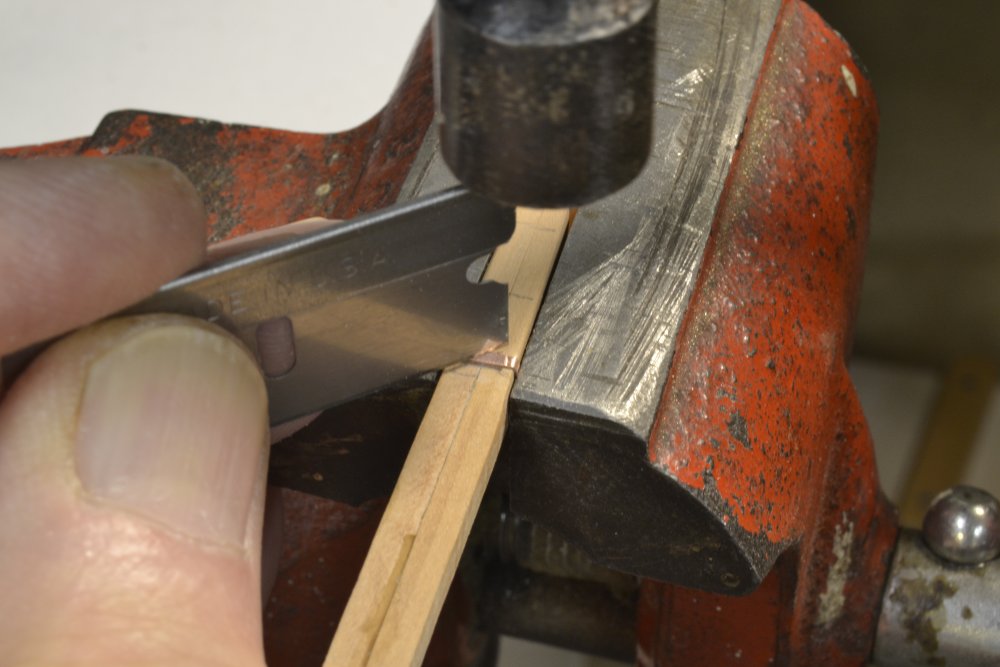
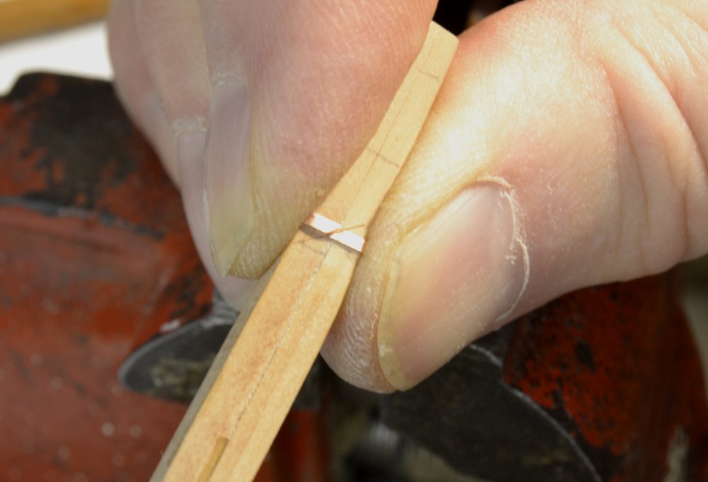
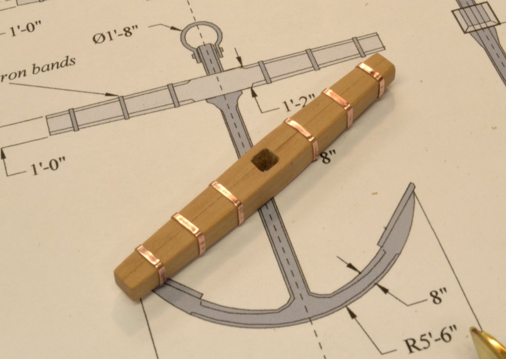
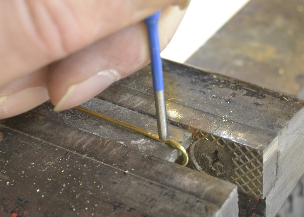
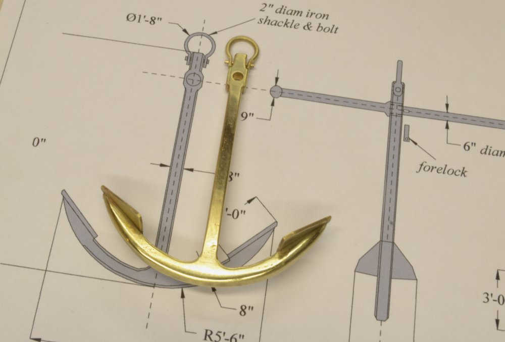
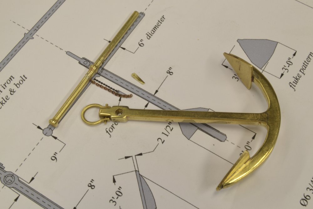
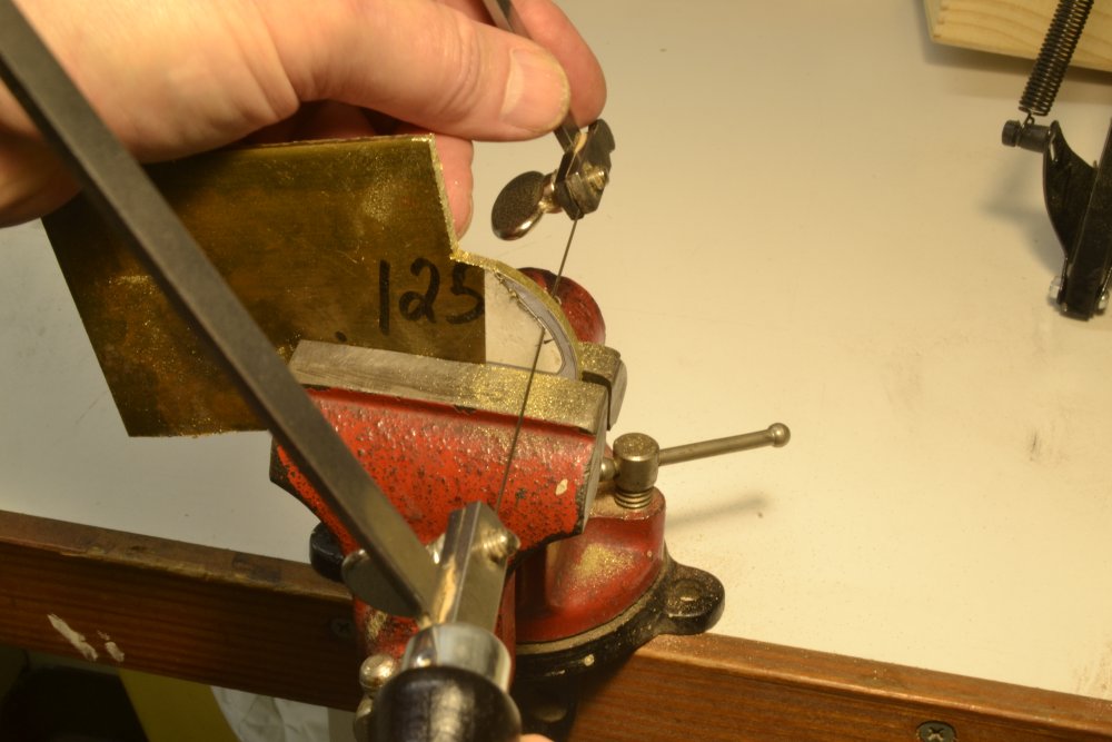
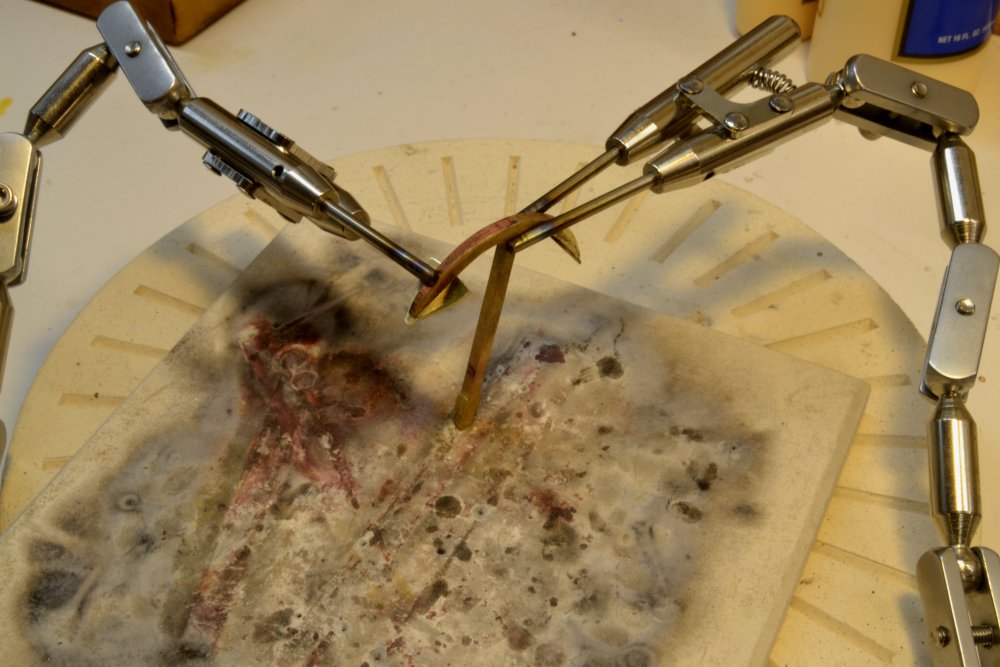
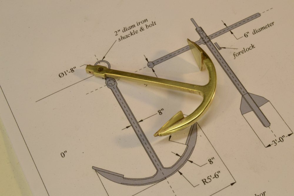
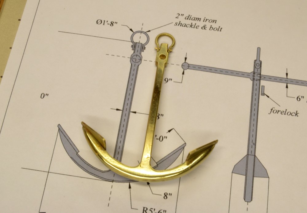
Young America - extreme clipper 1853 Part 163 – Bower Anchors 3 In the last part the fabrication of what will be the port bower anchor was completed. That anchor has still to be blackened and mounted. Work on the starboard anchor went on concurrently and is described in this part. In the first picture the shaft and arms of that second anchor have been soldered and it has been set up to solder some short lengths of telescoping square tube that will be used to shape the boss for the wood stock. The configuration is different from the first iron bar stock anchor. In the next picture shaping of the fully soldered anchor has just begun. On the first anchor the shackle bolt was soldered in place on the finished anchor. On this anchor the wooden stock must be installed before the shackle so the shackle bolt was threaded into the shackle to avoid soldering with the wood stock in place. The threaded rod and shackle are shown below. The still unshaped anchor is also shown in this picture. The shackle threads were made with a jeweler’s tap and die. The next step was to make the wooden stock. In the next picture one of the two halves is being mortised to fit over the square anchor shaft. Before final shaping of the wooden stock, the iron bands were made. This may appear backward in sequence but I think it is easier to do the final fitting of the bands by light sanding/filing of the wood stock, rather than to precisely size the bands. To accurately shape the bands a wood form was made to match the anchor stock shape. This was marked for band location and copper strips were bent around the form at each location. In the next picture a razor blade is being tapped with a hammer at an angle to cut the overlapped band to precisely size it and form the joint for soldering. The next picture shows the band joint (and the cut damage to the wood form). It was then removed from the wood, soldered, replaced on the wood form and cleaned up with files and abrasive sticks. Using the wood form for fitting, clean-up and polishing avoids damage to the actual stock and also keeps it clean of metal dust. In the next picture the six bands have been fitted. Fitting of the bands required light filing sanding of the wooden stock to the point where each band would fit tightly at its final location. In the above picture the polished bands have been pressed into place, and are ready for blackening. In the last picture all of the iron parts have been blackened and the anchor is ready for assembly. All of the metal parts were pickled in heated white vinegar, polished, soaked in TIVA cleaning solution, and rinsed before treatment. The copper bands on the stock were brushed liberally with liver of sulfur solution. When black, the assembly was rinsed in clean water. The brass anchor and shackle parts were dipped in diluted Birch-Casey brass black, brushed until black, rinsed, buffed with Q-tips, and allowed to dry. The tight fit of the bands on the stock and the stock on the shaft may be sufficient without glue. I may use a tiny drop of CA on the underside of each band and on the anchor shaft just to be safe. The anchor shackle will be attached to a soldered chain shackle so will be installed later when those parts are made. Ed
- 3,618 replies
-
- 44
-
-
- young america
- clipper
- (and 1 more)
-
Thank you all for the comments and likes. Very perceptive, Micheal. I see I cannot get away with anything here. A number of things are going on here. First, the length of the anchor and the bar are based on a rule of thumb that they be equal in length. The drawing was based on a length of 13'-0". Subsequent checking of sources argued for a lengths as small as 12'. The as-built length of the anchor is about 12' 6" and I made the length of the bar about the same. Therefore, seeing the bar slightly shorter than the drawing did not concern me, but when doing the final drawing check, I saw that the bar length on the drawing is too long because of the way I placed the ball at the end. The overall length has been corrected on the drawing. Both lengths are 13' as the drawing now stands. I may downsize it toward 12', but knowing that there was a lot of dimensional variation in these American anchors of the period, I may not bother. For example, Campbell (China Tea Clippers) gives a 12'3" overall length for a 1200 ton ship. YA was 1900 tons. So, welcome to my world. David, I did not bother with any lubricant. I try to avoid using it around the lathe (and mill) to avoid getting it on wood pieces. Using the chuck as a tailstock center was pure expedient. A better method would be to use a short piece of 1/8" id tubing held in the chuck. I could easily have done this but wanted to try the chuck. It worked fine. Tom, I glossed over many of the steps in the process, but I am documenting it better for future reference. I should have some pictures of the second anchor within a few days. Ed
- 3,618 replies
-
- 8
-
-
- young america
- clipper
- (and 1 more)
-
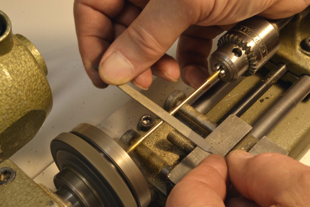
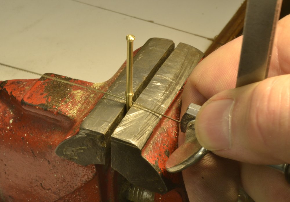
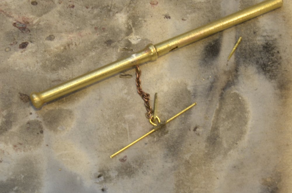
Young America - extreme clipper 1853 Part 162 – Bower Anchors 2 Although I worked on the two bower anchors simultaneously, I will stick with the iron bar stock version through to its completion, then post the work on the wooden stock version in one sequence. Although very similar, there are a number of differences in their construction. There are a lot of steps to making these, so I will just summarize here. The first picture shows work on the large shackle at the top of the first anchor. The shackles on the bower anchors are by far the largest on the ship. In the picture one of the ends is being flattened to increase its breadth. It was then drilled for the bolt holes. The next picture shows the shackle bolted to the top of the anchor shaft. A touch of silver solder on one end keeps the bolt in place. Iron bar stock anchors were coming into use during the YA period. Some had a simple straight-ended bar. Some had screwed or pinned balls at the end and most of the later versions featured a right angle bend at the end. I decided on the simple straight bar. In the next picture the 6” diameter bar stock, with its two 9” bosses, is being turned from a 1/8” brass rod. The rod is held on center at the tail end by the drill chuck just lightly tightened. A file is being used to finish the diameter. Flexing in long thin turnings like this makes final sizing difficult with cutting tools but the file works fine on the last 10 thousandths or so near the middle. In the next picture the bar has been finished turning, cut to length and drilled for the forelock that will keep it in place on the anchor shaft. In the picture a jeweler’s saw is being used to cut the slot for the forelock. In the next picture the bar has again been drilled, this time for the eyebolt that will secure the forelock chain. The eyebolt with chain was then soldered into the hole. I am making all eyebolts from twisted wire, in this case the wire was passed through the chain before spinning it up. The next picture shows all the parts for this anchor, including the forelock. I want to blacken the bar assembly and the anchor separately. The bar will finally be held in by the forelock. The next picture shows the forelock and the chain connected by a shackle. On small shackles like this one the bolt end is simulated by silver soldering a straight brass rod across the ends. I expect to use this method on the many rigging shackles to come later. By the period of this ship shackles had largely replaced ringbolts that had to be permanently forged to the eyebolt beforehand. The beauty of the shackle was that it could be easily fitted and removed. The method shown above offers no such advantage as will be seen later where shackles are fitted to eyebolts in wood or in rigging. In the above picture the shackle has been prepared for soldering with both the chain and the forelock threaded onto it. I used easy solder and a very light pass with the torch to prevent welding the whole array together in one blob. The last picture shows the completed anchor. I almost hate to blacken this. Ed
- 3,618 replies
-
- 39
-
-
- young america
- clipper
- (and 1 more)
-
Very nice work, Frank - very precise, very clean. Don't beat yourself up over the mistake. We all make plenty of them - and some even see the light of day. I would consider Druxeys solution or ignore it. Ed
- 649 replies
-
- 8
-
-
- dunbrody
- famine ship
- (and 2 more)
-
Beautiful work, Frank. Your meticulous style is making me crazy. Ed
- 649 replies
-
- 4
-
-
- dunbrody
- famine ship
- (and 2 more)
-
Dirk, the soldering fixture is available from the same source as the link posted above. The clamps are very solid and the jaws are tungsten. Ed
- 3,618 replies
-
- 4
-
-
- young america
- clipper
- (and 1 more)
-
Thank you, all. The joints are silver soldered. I have been using copper-phosphorus solder in paste form with flux from a syringe. I believe this solder blackens easier - particularly if using liver of sulfur on copper. The solder has a lower (only 3%) silver content and melts at 1325 deg F. On the flukes I used Easy grade that melts at 1205 deg F. I use a propane torch for soldering - s mall one on small parts. I used a full size torch on some of the anchor work for more heat. As I said in the post, I would have used oxy-propane instead of the the large torch, but was out of oxygen. It goes fast and is expensive. I will be blackening the anchors with Birchwood Casey selenious brass blackening solution. A link to my source for solder is given below. Joints for silver soldering must be tight because the solder - unlike soft solder - will not fill gaps. For this reason joints are very thin and become relatively invisible when filed off. https://contenti.com/jewelry-soldering-supplies/solder Ed
- 3,618 replies
-
- 11
-
-
- young america
- clipper
- (and 1 more)
-
Thank you all very much, but lets not go overboard. I'd much rather talk about anchors - or even deadeye chains. Ed
- 3,618 replies
-
- 6
-
-
- young america
- clipper
- (and 1 more)
-
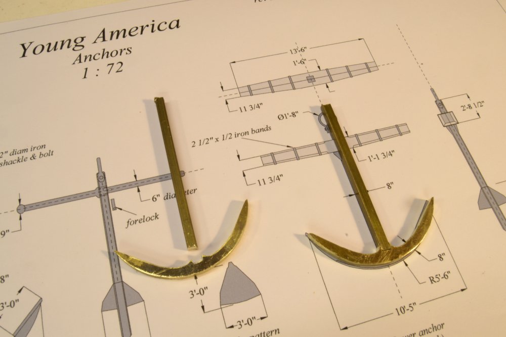
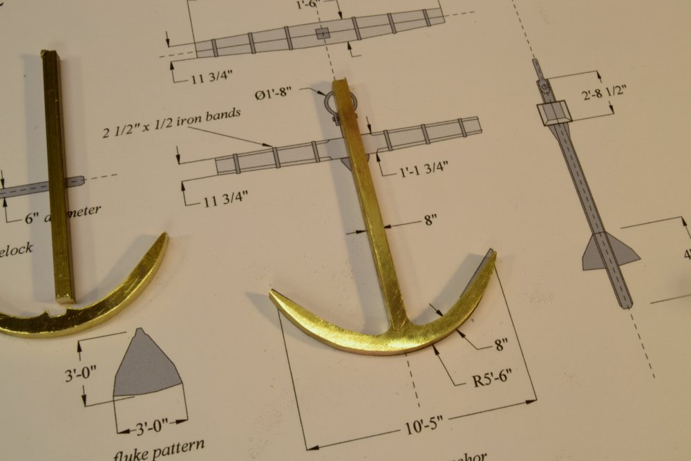
Young America - extreme clipper 1853 Part 161 – Bower Anchors 1 Work on the channel deadeyes and chains has been progressing, but a change of pace was necessary, so I began work on the ship’s anchors. Like most ships Young America carried several – probably two bower anchors, a smaller stream anchor and an even smaller kedge anchor. This last was probably small enough to be stowed in one of the forward lockers or below the forecastle so I will not model it. Over her very long career she carried different types of bower anchors, and very likely more than one type at a time. The photo taken at San Francisco, probably in the 1860’s shows her swinging a wood stock type from her starboard cathead. The New York photo, which I believe was taken later, shows a Trotmans anti-fouling type on the port cathead. These two types span the range of development during the period. I decided to make one Woodstock and one bar stock – bypassing the Trotmans type for now.. The first picture shows the arms of one of these being sawed out of some 1/8” thick brass plate. This took a while and used a few jeweler saw blades, but it worked well to rough out the pieces using a drawing fragment as a pattern. The next picture shows both bower anchors during fitting of the two main pieces. The shaft was silver soldered to the arms using copper-phosphorus solder. The anchor to the right has been soldered and given a first filling. This joint took some heat. I used a full sized propane torch. I would have used the small oxy-propane torch but was out of O2. In the next picture the side plates that thicken the shaft around the hole for the bar have been soldered on. The second fluke is set up to be soldered. In the next picture the flukes have been soldered on and the holes drilled for the bar and the shackle. In this picture the filing and smoothing is well along. The final anchor, less the bar stock is shown in the next picture. This is almost ready for blackening. I expect to mount this anchor on the port side of the forecastle in roughly the position shown in the last picture and may secure the stream anchor to its shaft. These anchors obviously took up a lot of deck space and also added considerable weight to the bow, but this seems to have been where they were stowed. They were not easy to move around. Ed
- 3,618 replies
-
- 35
-
-
- young america
- clipper
- (and 1 more)
-
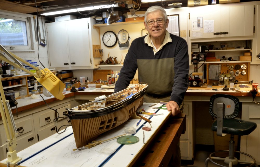
Robin, I usually do not let the camera lens wander above my wrists, but for you I make an exception - per your request.... Please excuse the typical clutter. All the best, Ed ps. should have an update posting shortly.
- 3,618 replies
-
- 46
-
-
- young america
- clipper
- (and 1 more)
-
Hi Gary. Great work. I agree with Laman about the hold down screws. Unless you have another plan for holding down the final model, now is the time. Model is looking great - and of course, so familiar. Ed
-
Most of the comments here, I believe, refer to spindle speed. For a given spindle speed, cutting speed varies with the diameter of the tool, or on a lathe the diameter of the piece. Cutting speed increases with diameter for a given spindle speed. So, cutting speed, ideally, should be optimized for each individual setup based on the speed of the cutter at the cut. Small diameter wood turnings, for example, require very high spindle speeds. High spindle speeds on turnings not only produces a finer surface but also reduces torque on the piece at the cut, reducing breakage. I believe the standard Sherline mill is a bit slow for routing wood, thus leaving a rough surface. Although I do not have the high speed attachment, I believe it would be a good investment. Would routers and Dremel type tools have very high spindle speeds for this reason - much higher than machining tools like lathes and mills that are basically designed for metal where recommended cutting speeds are much lower. Ed .
-
Hull length is 238', about 230' at the waterline, keel is about 220'. Ed
-
Thank you, Glenn and Karl. Seems like a while since the last update. Not too many pictures lately - unless there is interest in some of me at the computer working on rigging information - a major task. Ed
- 3,618 replies
-
- 6
-
-
- young america
- clipper
- (and 1 more)
-
Looking great, Gary. Ed
-
Thanks for that description, Glenn. It is true that timing is everything with this. I find the "black art" to be the most consistently unpredictable of all modeling processes. You have obviously mastered it. Ed
-
Glenn, your posts need a "love this" button. Truly amazing and beautiful work. I seem to remember from an earlier post that you used Birchwood Casey to blacken the brass. On these large pieces, I assume you are swabbing them full strength per their directions? I find that that works well using a Q-tip. Your blackening looks perfect. Ed By the way, the ruler in the pictures is most helpful.
- 701 replies
-
- 10
-
-
I have a thought on this that may be worth pursuing with some additional research. Refractory brick set on a flexible metal plate may not have had mortared joints. Any such joints would soon crack with the flexing of the deck. Mortar that worked loose would soon leave gaps, allowing radiant heat from the stove to reach the plate (or deck?) below. The brick or stone may have been contained in a frame and held closely like the joints shown in your photo. In the Victory restoration the brick (or stone) floor is contained with a wood frame outside the stove perimeter. If mortared, I believe the joints would be very thin - at least that is the current practice in my experience with refractory linings. I believe I would go without mortar, but that's just a guess. Something to chew on. Ed