EdT
-
Posts
2,214 -
Joined
-
Last visited
Content Type
Profiles
Forums
Gallery
Events
Everything posted by EdT
-
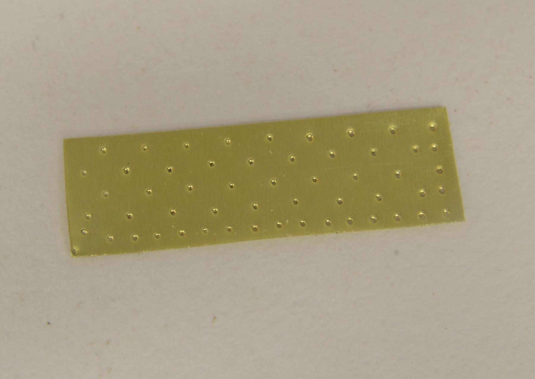
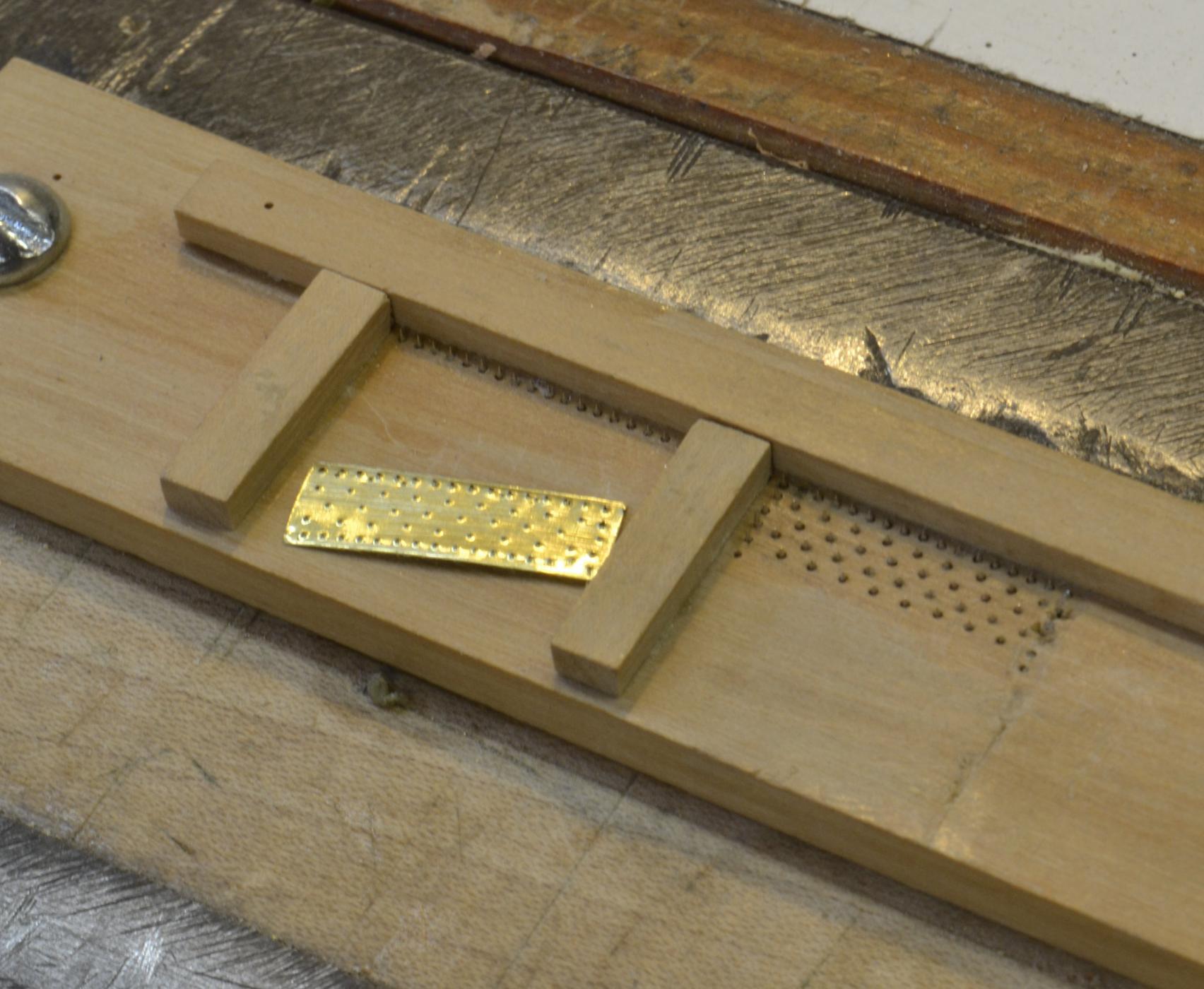
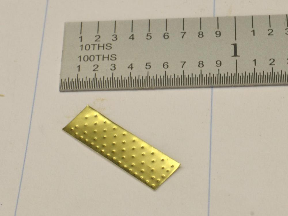
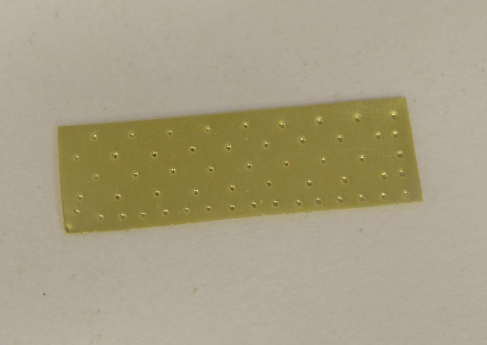
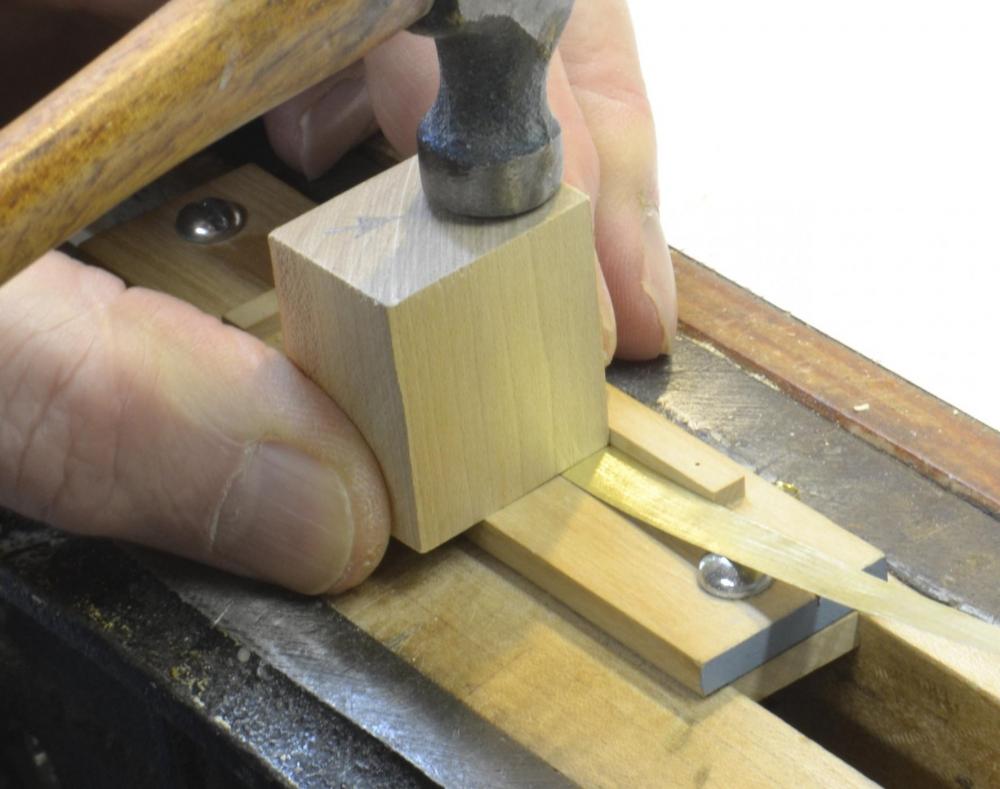
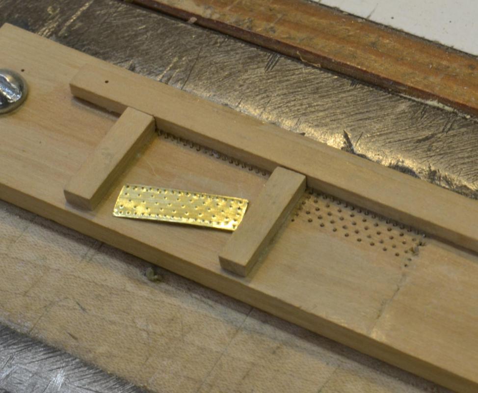
I agree with Druxey that at smaller scales, less is more. In my mind the question is one of proportionality. If something is out of proportion when modeled, it may be best to simplify, as Pete has done on his newsboy model, or to deemphasize the feature as Nils has done by flattening. I wrestled with the plate problem on my 1:96 Victory and on the 1:72 Young America models. On both I used an embossing jig with drilled nail spacing and pattern that approximated the originals. This required some precision drilling and refinement of the embossing pins that were used in it. I also used flattening. Because these sheets were thin and nailed, the plate indentations should be inward, not projections. Here are some pictures showing the method and results. This has been described on this site and of course in the YA book, and may be worth a look. Rob, are you also certain that GR was sheathed in copper and not yellow metal (zinc+copper=brass)? Ed .
- 1,208 replies
-
- 7
-

-
- great republic
- clipper
- (and 1 more)
-
Lovely work, Frank. Setting and holding an accurate deck beam centerline can be tricky. The centering ruler is a neat idea. In the 14th picture the ruler appears off center, but the string also appears off center. Am I seeing it wrong. Ed
- 649 replies
-
- 6
-
-
- dunbrody
- famine ship
- (and 2 more)
-
Frank, I don't have an answer but will comment. The purpose of the knees on the stanchions was to allow them to function in tension as well as compression, so if this was part of the design they should be fitted at both ends. Stanchions on decks above this could be through bolted with long tie rods, but that cannot be done on the keelson. The knees might be either iron or wood. My guess would be iron for an English/British ship, wood for a mid-century American ship - but who knows. Ed
- 649 replies
-
- 6
-
-
- dunbrody
- famine ship
- (and 2 more)
-
The frames are labelled DF for dead flat. These are the midship frames. Files names do not have the dead flat symbol. Ed
-
Rob, YA was fitted with double topsail yards in 1854 about a year after her launch. Based on the date and the two photographs, I believe that she had the Howes Patent type. These were first adopted in 1853 and the Howes patent was granted in 1854. The other type in use at that time was the Forbes rig, in which the yard was held by an iron fitting that slid up and down the lower mast head. The Howes version, also using an iron fitting was bolted in a fixed position to the lower mast cap with a supporting strut to the lower mast head. In both YA photos the yard is clearly fixed to the mast cap, so at this stage, that is my basis. Ed
- 3,618 replies
-
- 4
-
-
- young america
- clipper
- (and 1 more)
-
Thank you, Frank. Most appreciated. Progress reports on YA may be sparse for awhile. Work on Volume II is beginning to suck up all the oxygen. Ed
- 3,618 replies
-
- 4
-
-
- young america
- clipper
- (and 1 more)
-
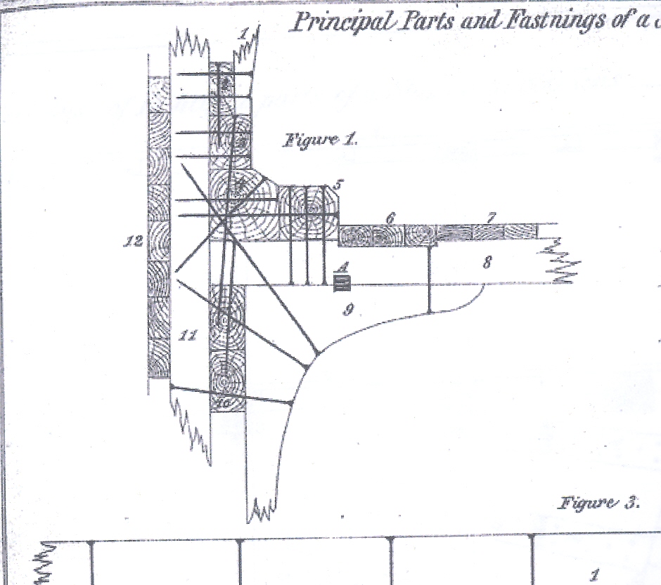
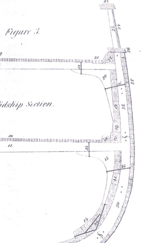
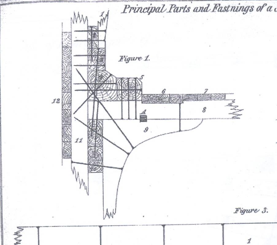
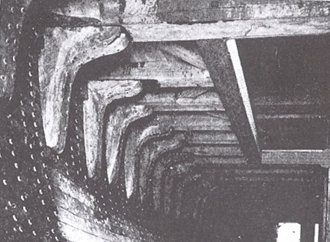
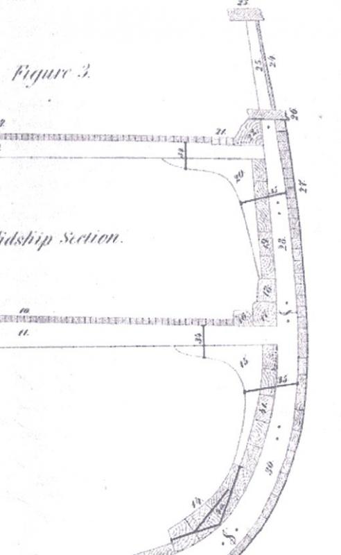
I believe Frank's interpretation of the knee design for the ship in question is very probably correct given the practice at the time and the availability of strong riveted iron bolts that were not available to earlier ship structures. I say "very probably" because most of my investigation involved American ships. With the knees beside the beam the top fastenings would be in shear. While this offers no advantage when considering the strength of the fastening itself, it would have be of advantage with early fastenings in tension because of their lower extraction resistance. However, even with the knees side-bolted at the top, they were still bolted from the inside through the frames, raising the question of the reason for the side bolting at the top. Perhaps it required less fitting of the knee (only one face vs. two.) or was better for headroom with the low deck heights of the time. Anyway, I researched this issue when drafting the structure for Young America. Bill Crothers was quite clear on the arrangement - see p 240 of American Clipper Ships and/or p 209 in his book on packets. These knees are clearly on the beam center line - ie bottom mounted. Although I had great confidence in Bill's conclusions, I looked for further primary source data. This can be found in the following diagrams extracted from the American Lloyds Registers of 1857 and 1867 respectively. These documents defined acceptable shipbuidling practices at the time. Although titled "American" I believe they were consistent with British standards. The third image is a photo from Desmond on Wooden Shipbuilding showing knees in the beam centerlines. Ed
- 649 replies
-
- 15
-
-
- dunbrody
- famine ship
- (and 2 more)
-
Fantastic work, Frank. The precision is extraordinary. Ed
- 649 replies
-
- 4
-
-
- dunbrody
- famine ship
- (and 2 more)
-
Yes, a clean joint at the feet of the cant frames requires a squared off rabbet along the bearding line and tight fitting square ends on the frames so when they are sanded fair the line remains a smooth clean one. Easier said than done but yours look fine from the photos. This single curved bearding line vs. the stepped versions on earlier ships has its pluses and minuses from a modeling standpoint. Ed
-
Very nice work, Gary - and only a couple hundred hours work? Amazing. By the way, I keep meaning to mention - Naiad's launch date was 1797, not the 1787 in your title. the difference is that the correct date places her in the building program that supported the French wars that began in 1793, a period when British frigate design was desperately trying to compete with their French adversaries - at a time when French designs were being adopted in small degrees to address the (at least perceived) deficiencies. Naiad, with a gun deck length of 147', represents one design version of several (each increasing in length) between the first British 38's (Minerva Class, 141', 1787) to the final development of the British 38's, represented by the very successful 150' Leda Class (1800), of which some 39 ships were built into the 1830's. This very gradual, progressive increase in length to overcome sailing problems with the battery of 28 18-pounders on the gun deck has seemed to me a monument to penny-pinching, conservative, incrementalism - a futile rear guard action against the increased costs of longer ships to effectively carry the larger armament. Contrast this to the American leap from nowhere to the 175', 24 pounder, 44's with Constitution, President and United States in 1796. Different navies, different missions, but certainly a more progressive advancement in design - as the War of 1812 battles attest. Ed
-
Beautiful as always, Gaetan. I am behind in following the work. The camera setup just caught my eye. I have more than enough trouble avoiding tipping over just one tripod! Ed
- 728 replies
-
- 3
-
-
- le fleuron
- 64 gun
- (and 1 more)
-
Hello, everyone. I have been away on vacation for the past couple weeks and have not been keeping up with the postings. Thanks for the recent comments. I hope to be back in the shop soon. Bob, using the drawings pens for CA is interesting - perhaps a good use for these unused tools. Ed
- 3,618 replies
-
- 5
-
-
- young america
- clipper
- (and 1 more)
-
E&T, I love the wheel. Beautiful piece and a great lesson for those without machine tools. Ed
- 346 replies
-
- 4
-
-
- terror
- polar exploration
- (and 2 more)
-
ancre La Salamandre by tadheus - 1:24
EdT replied to tadheus's topic in - Build logs for subjects built 1751 - 1800
Lovely clean work, Paul. Ed -
Decisions, decisions. Isn't it great to keep the brain working. I would certainly leave some of that beautiful framing work and bolting exposed. Also, I found that deck clamps spanning the viewing ports were more than strong enough to support the deck beams without leaving those frames in place - blocking the view inside. Ed
- 649 replies
-
- 5
-
-
- dunbrody
- famine ship
- (and 2 more)
-
Thanks, again, everyone. Nils, the twisted wire is very easy to do. I have made several sizes of eyebolts by this method some with shackles or chain pre-fitted. I will be experimenting with very small gauge wire to make wire rope and possibly simulate the very smallest rigging chain that is much smaller (~100 links/") than can be purchased. Joe, CA glue is soluble in acetone before and after curing, so it can be used to clean up excess and break cured joints. It may take some time to dissolve cured CA. CA manufacturers also sell solvent but I have not tried it. For the joints shown, I soaked up excess first with a bit of paper towel right after applying it, then swabbed off the surface excess with a Q-tip dipped in acetone - not too much that would soak the joint. I have had no problem with the actual joints, since the acetone is just wiped over the surface and evaporates very quickly. If a lot of un-wiped glue is present, a white residue may be left. The area was filed off smooth after curing. You may be aware of this, but I will mention that caution is needed with cotton around CA. While there is not a problem with cotton dampened with acetone for small clean up, dipping cotton into CA can be very hazardous. The very high cellulose surface area of cotton can cause rapid polymerization of the CA and the heat of polymerization can/will ignite the cotton - and possibly the bottle of CA. If you have ever spilled a bottle of this stuff you will know what I mean about rapid polymerization I usually dispense a drop or two of CA on to a plastic can lid then pick up some with the applicator or sometimes dip the applicator into the open bottle - but with the bottle always contained in a wood base to prevent it tipping. Once upon a time I did tip over a bottle and do not want to do it again. I use as little of this stuff as necessary. Ed
- 3,618 replies
-
- 10
-
-
- young america
- clipper
- (and 1 more)
-
A new tool, Maury. I used to make CA applicators by sawing a small slit in the end of a brass wire that would hold a small droplet. The applicator shown was made by the method I am using on eyebolts - taking a length of brass wire, bending in in half, securing the ends in a vise, hooking the loop in a hook (pin or brass wire) in a hand drill then twisting it up. Either the loop end or the small fork clipped off at the vise end can be used to hold a glue drop. The loop end needs to be cleaned in solvent; the fork end can be clipped back and a new fork formed. Different sized wires can be used. I believe the wire in the picture is 24 gauge from a spool.
- 3,618 replies
-
- 8
-
-
- young america
- clipper
- (and 1 more)
-
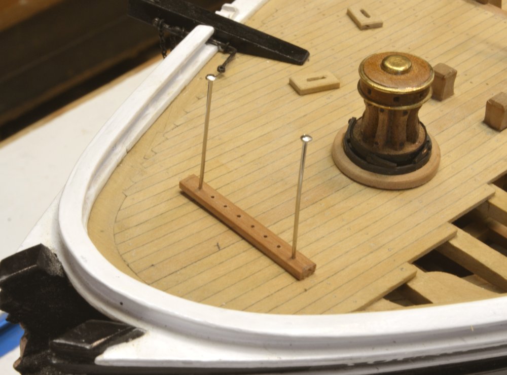
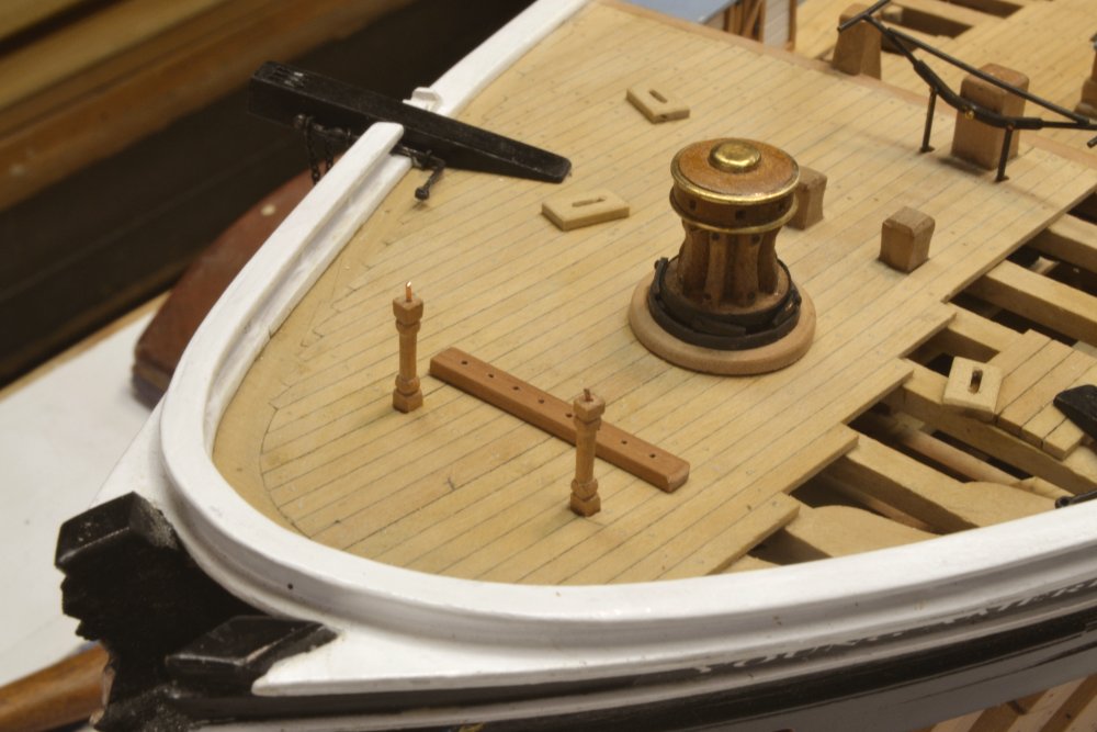
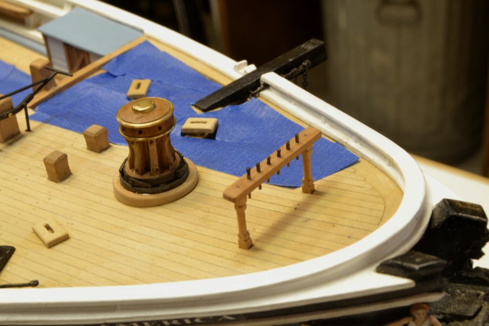
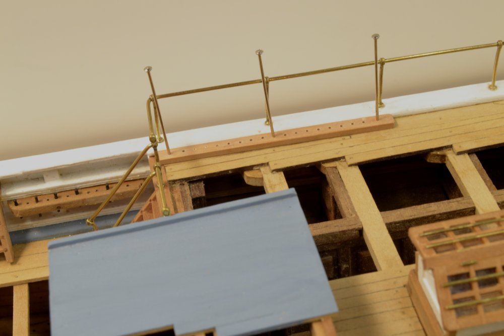
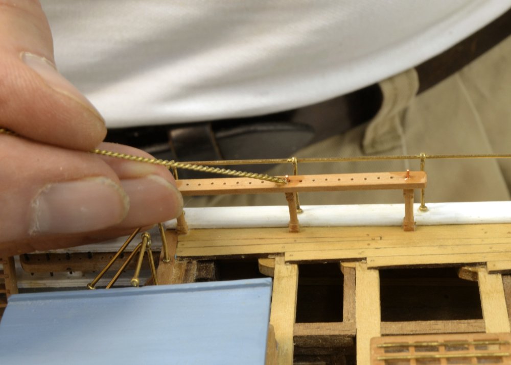
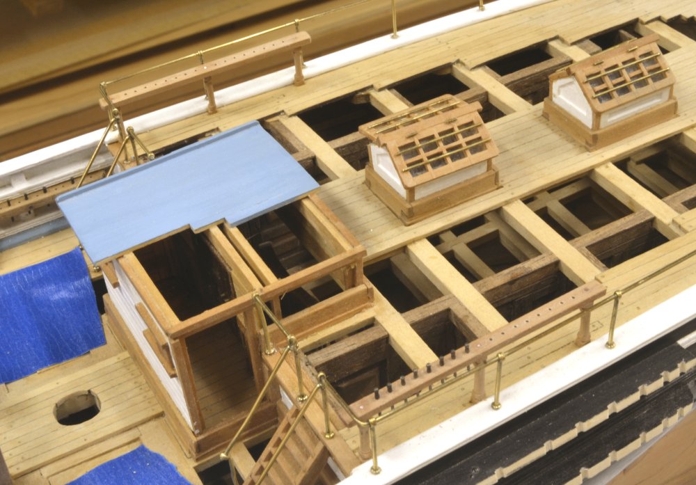
Young America - extreme clipper 1853 Part 165 – Forecastle/Poop Pin Rails Another small task was slipped in to break the monotony of deadeye chains and belaying pin turning. In the first picture the forecastle pin rail has been made and is being used as a template to spot the centers of the posts on the deck. The location is over a beam. The posts will be set into square mortises cut into the deck to provide more strength to this type of rail. In the next picture one of the mortises is being started with perimeter cuts using a small chisel. The turned posts are 5” (.07”) square, turned as was done for the fife rail posts earlier. In the next picture the two posts have been set and fitted with pins in the top to secure the rail. In the next picture the rail has been installed and the six pins added. This is a light duty rail, used to belay the four jib and fore staysail downhauls as well as the two foresail bowlines. Providing belaying points for the running rigging of the mizzen mast proved to be a puzzle. There are some two dozen light lines associated with the mizzen sails that need to be belayed aft of the mast, below the shroud fairleads through which they run, but with the lack of a raised bulwark on the poop there is no clear place for belaying pins. The poop deck perimeter will be packed with cleats and lead blocks for heavier lines and the spider band around the mast is fully allocated. The photo of the ship from the starboard quarter is not very helpful. Time for some historical interpretation – not the first or the last. I believe there are four possibilities. First, that the poop monkey rail itself was fitted with pins – unlikely given the small section of this brass rail. Second, using shroud cleats, but these would be visible in the photo. Third, using deck cleats as with the heavier lines, but the sheer number of these and the resulting mass of line piled on the deck argue against this. I finally decided on the fourth option, pin rails similar to the forecastle rail along each side of the forward poop rails. This was a common method. The next picture shows one of these rails positioned on the deck to spot mortises for the three posts. In the next picture the rail has been set as with the forecastle rail and a drop of CA is being applied to each of the vertical wire bolts. The posts of all these rails were glued into the deck with wood glue and the tops with CA. After applying the drops to the top of the rails it was washed off with acetone. The bolts were later clipped off and the tops sanded. The last picture shows the two rails installed with the rail on the near side already being fitted with pins. The complement of belaying pins is almost complete – a few dozen to go. Ed

- 3,618 replies
-
- 46
-
-
- young america
- clipper
- (and 1 more)
-
Looking great, Frank. I can relate to your comments on intentional grain-raising as part of the finishing process. I think this is good practice on all woods where a water-based finish - water stains, dyes, acrylic paints, inks, etc. - are used - or even in general for uniformity if glue has been washed off with water. I do this routinely on model wood and did it for years on furniture work before final sanding - all hardwoods. I used clean water. I have not tried alcohol. If the grain is not raised before finishing, the water in the finish will do it, often requiring more sanding. Those planking clamps really come in handy on that internal bilge planking. Keep in mind that over-tightening these in these positions can distort the frames outwards. I did not find that to be a problem, but I believe it could be, depending on the molded breadth of the frames and the amount of stress - probably not a problem with the toothpicks(?) you are using, but with the nails I used, you can put a lot of stress on the frames. Worth a check. Ed
- 649 replies
-
- 5
-
-
- dunbrody
- famine ship
- (and 2 more)
-
Good question, Frank. I cannot remember this being too much of a problem. Is the epoxy fully hardened when you file it. If so and the file still loads up with resin, all I can suggest is frequent use of the file card. I don't use any solvent on the epoxy, but just let the blobs harden, clip them and the protruding wire off with cutters, then file off the remainder. Any solvent used to dissolve off glue will cause it to penetrate into the wood. Perhaps the alcohol is inhibiting the hardening of the epoxy? Ed
- 649 replies
-
- 4
-
-
- dunbrody
- famine ship
- (and 2 more)
-
Great work, Frank. As you probably know, I used epoxy rather than CA to fix the functional copper bolts, partly because of the glue stains on the wood that you experienced. The CA penetrates the wood so is hard to remove, even if you wash it off right away with acetone. This method, of course, involves a lot of solvent use. Epoxy, even though it is time consuming to mix batches as you work, seems to come off the wood a lot easier. I would use files. Files seem to do a better job on both glue types than sandpaper. Sandpaper rides over hard areas, so I save it for the final wood finish. The neat regular spacing of your bolting is really nice. Ed
- 649 replies
-
- 4
-
-
- dunbrody
- famine ship
- (and 2 more)
-
Jan, an interesting question. The anchors were handled primarily by two triple purchase tackles - one was reeved, when needed, through the sheaves on the cathead, the other, the fish tackle, was suspended on these ships by a pendant seized with a collar around the fore topmast head. Other tackles and tools were used depending on the stowage position of the anchor. Both purchase falls were fitted with large hooks to grasp the shaft or bills of the anchors. With the stowage position and release gear shown in the pictures above, I suspect that the pinned release chain and the main chain cable was secured before the lashings, aka shank painters, were loosened. A smaller tackle was probably secured to the upper end of the stock to keep it upright and prevent anchor from rotating into the side of the hull. The lower end anchor would then be somehow pried or jacked outboard and lowered by the fish tackle to the release position, where all the tackles would be removed. With the extreme outward flare of the bow on these ships the lower end of the anchor did not have to be moved to far outside the rail to be clear of the side below. As a non-seaman, based upon some almost undecipherable texts, this is my best guess. Recovery would be roughly the reverse of this process. When not in use, the fish tackle hook was usually secured to the lower end of the fore stay and the cat tackle removed and stowed under the forecastle or in one of the forward lockers. Ed
- 3,618 replies
-
- 6
-
-
- young america
- clipper
- (and 1 more)
-
Thanks, everyone. Carl, the third and fourth pictures may be causing some confusion. In the third picture the chain shackle is about to be soldered on upside down and in the fourth picture the incorrect assembly is shown in place with the pin support upside down. I should probably put these pictures in the "reworked" file and not have used them. This error was corrected before blacking and installation. If you focus on the drawing shown in the second picture and understand that the light colored pin on the drawing lies loosely in the spoon at the end of the lever, you can see that when the lever is raised and its shaft rotated that the light colored pin will no longer be supported and will drop, releasing the chain that was shackled to it. On the model the parts are soldered together - a non-working model. Ed
- 3,618 replies
-
- 3
-
-
- young america
- clipper
- (and 1 more)