EdT
-
Posts
2,213 -
Joined
-
Last visited
Content Type
Profiles
Forums
Gallery
Events
Everything posted by EdT
-
Thank you, all, for the recent comments and likes, and thank you, Bob, for the very nice note. Very generous to say the least. Thank you for your best wishes. I do hope you will find the YA book interesting and useful. With regard to your order, I will contact Bob Friedman at SeaWatch and ask him to check. He may have already seen your posting, but I will followup for you. I have not been posting at the usual rate, because model work has been deferred for the past few weeks as I wrestle to get Young America II to the publishers. This has taken a lot of time and I hope the result will be worth it to readers. I should be back in the shop soon. Thanks again. Ed
- 3,618 replies
-
- 7
-

-
- young america
- clipper
- (and 1 more)
-
Amalio, I am just discovering your postings and am fascinated by the method. I am not sure I understand, but do you intend to remove the inner model supports and replace them with atcual framing while the outer molds hold the planking in place? Fascinating. Beautiful craftsmanship. Ed Translation from Google: Estoy descubriendo sus publicaciones y estoy fascinado por el método. No estoy seguro de entender, pero ¿tiene la intención de quitar los soportes del modelo interior y reemplazarlos con el marco atcual, mientras que los moldes externos mantener el tablaje en su lugar? Fascinante. Hermosa artesanía.
-
Wow, W2YSM, I am really behind in following this blog - a year since my last visit. Somehow I missed the notice on your post. Sorry. I am glad the YA POB work was helpful to you. Hakan, I feel your pain with the wall board and floor sanding - tasks that I am grateful are far in my past. Ed
- 191 replies
-
- 2
-
-
- young america
- clipper
- (and 1 more)
-
Christian, the temporary dust case I am making to fit the 1:72 rigged model is 60" long, 39" high, and 19" wide. For the 1:96 version, this would be about 45" long, 29" high, and 15" wide. Thanks for your innterest in modeling her. You are right. She has beautiful hull lines. I often take time out to just look at them. Ed
- 3,618 replies
-
- 5
-
-
- young america
- clipper
- (and 1 more)
-
Thank you, all. Frank, the drafting has been a major part of the project and its complexity is ramping up as rigging approaches. One of my goals is to adopt a new approach to presenting rigging information. I think this may be warranted by the inclusion of many lines on the model that are often omitted from the usual rigging drawings or many models. For example, even Crothers extremely well done and detailed drawings exclude many important lines, like sheets, bunt and leech lines, reef tackle, to say nothing of running rigging associated with fore and aft sails - jibs, staysails, etc. Even if some would decide to omit these lines from models, I wanted to include them in the design. Even at this level, I am not planning to describe or model the running rigging for studding sails that was usually stored with the sails and would not appear on the ship at most times. Including all this on a typical rigging plan (or plans) would result in unreadable drawings. Also, the usual method of a belaying pin diagram that relates a pin number to the name of the line has always left me frustrated with the amount of cross-referencing left to the modeler. Finally, I think rigging can be made a lot more understandable and user friendly if preparation for it begins early in the modeling. Hence, you will see rigging line numbers appearing on deck plans, spar and spar furniture drawings, sometimes along with rigging elements like blocks, shackles, etc, that are best installed early, as the pieces are made. So far, this is working out well from the modeling standpoint but has added work to the drafting and other document preparation. I am finding the process fascinating and hope to say more about it and specifics as work proceeds. I should say that some gratitude is owed to author's who have influenced my thinking on this in earlier and present work: Longridge, McKay, and Underhill. While I am not duplicating their presentations on rigging, they have influenced my thinking and been very helpful. McKay with the Victory Rigging List. Longridge and Underhill with their setup notes and diagrams. I should note that much of the design is coming from contemporary sources like, Luce, Murphy and Jeffers, Kipping, Biddlecomb, and others. So, a long story but one I hope will generate some interest. Ed
- 3,618 replies
-
- 14
-
-
- young america
- clipper
- (and 1 more)
-
HMS Naiad 1797 by albert - FINISHED - 1/48
EdT replied to albert's topic in - Build logs for subjects built 1751 - 1800
Lovely work, Albert. Ed -
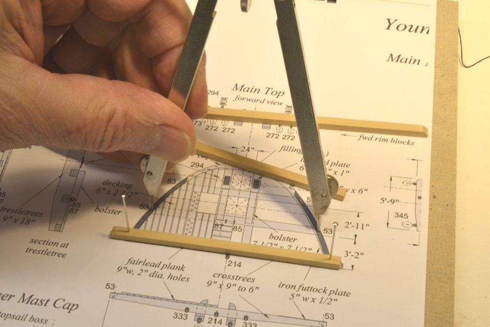
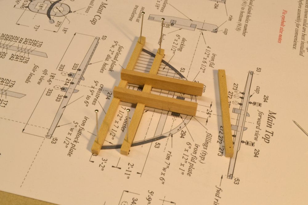
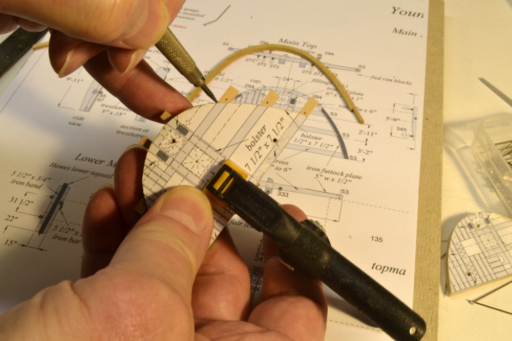
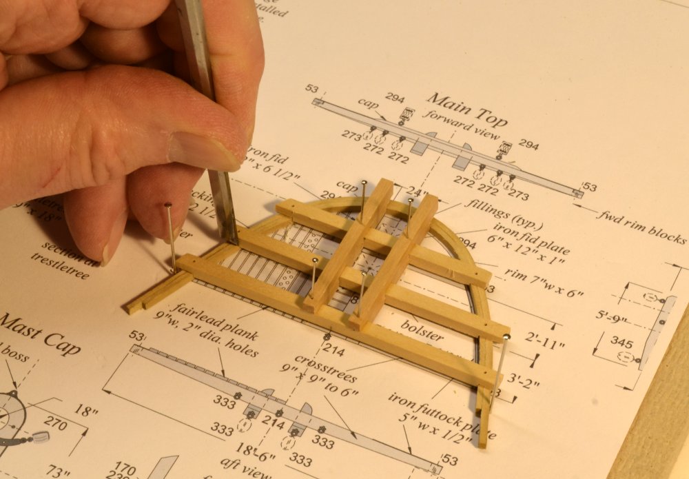
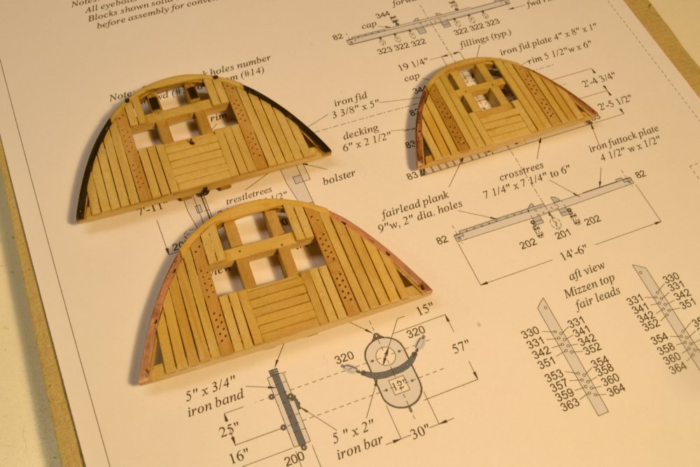
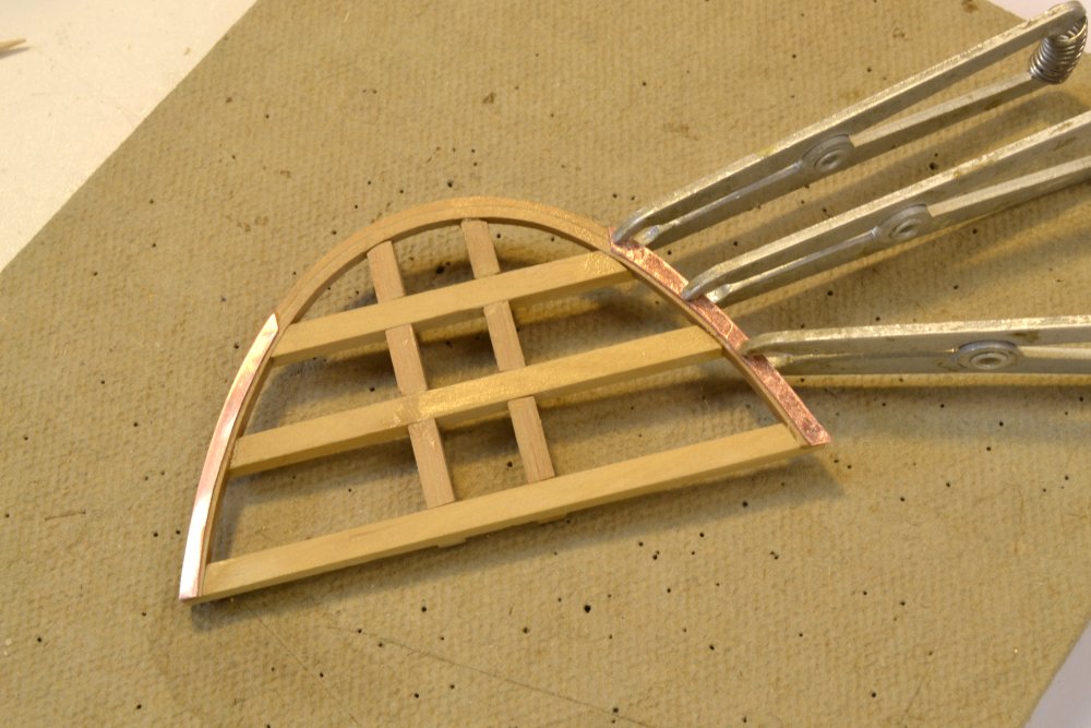
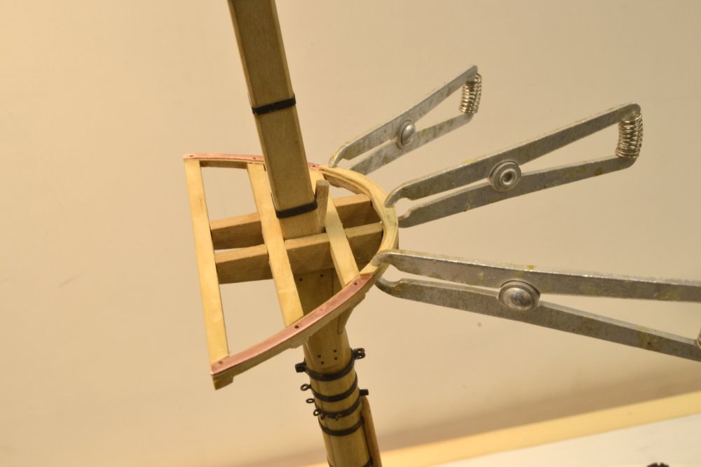
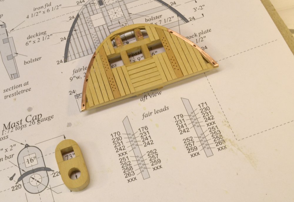
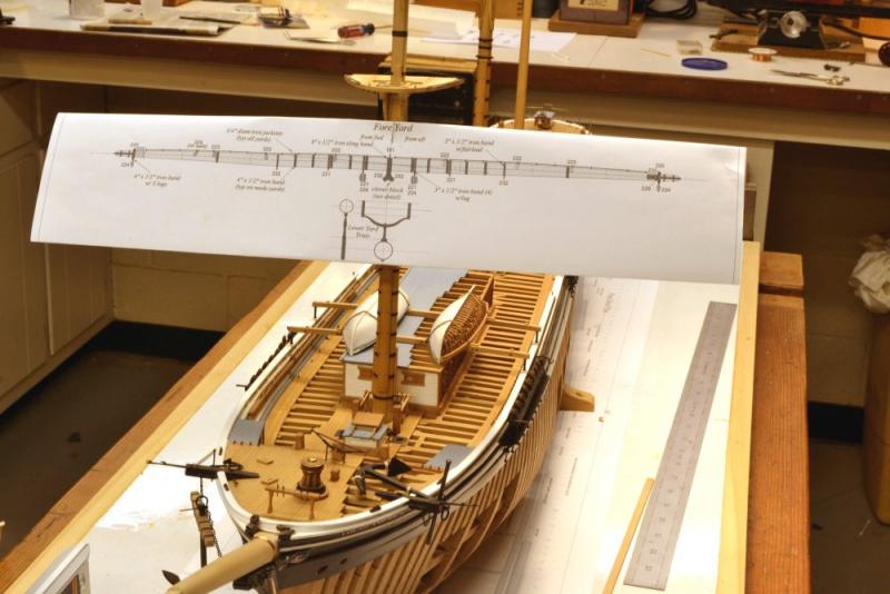
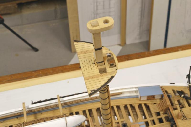
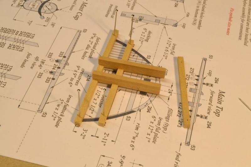
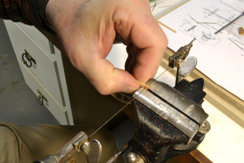
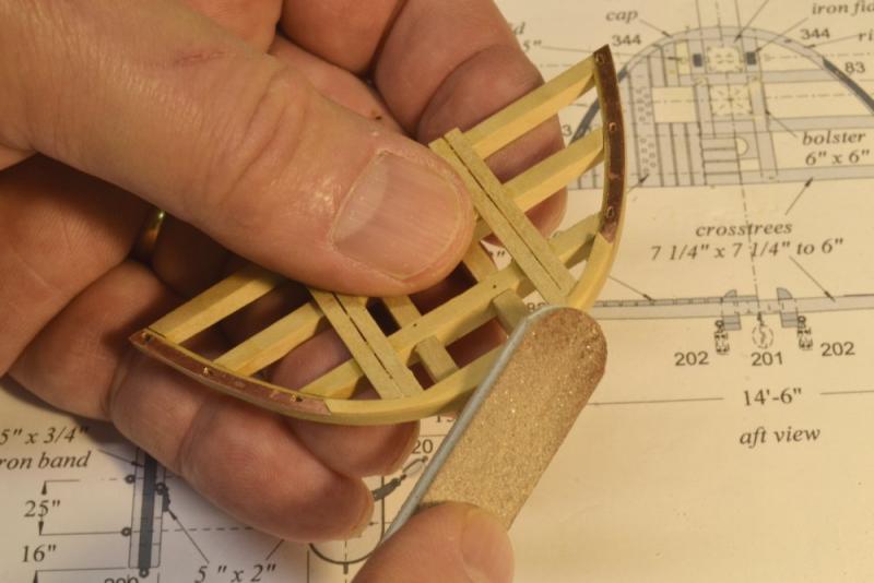
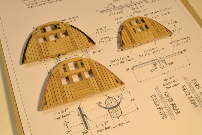
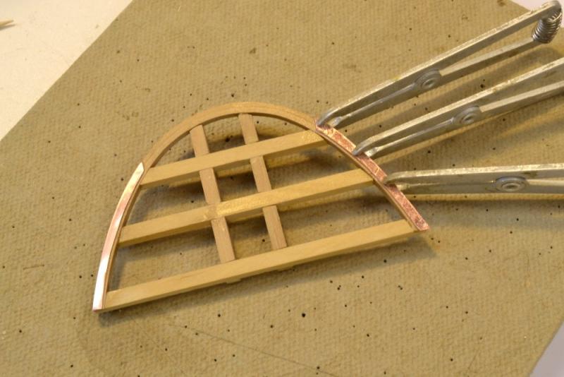
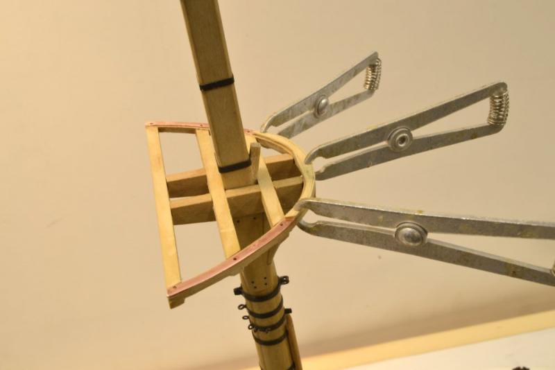
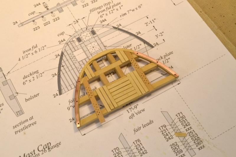
Young America - extreme clipper 1853 Part 192 – More on Tops The holiday season is a time for reflection and I have been thinking about the work ahead on YA in the New Year and beyond. One of the approaching tasks is to finish the dust case that was started in an earlier post. This project always gets me thinking about the size of the model. The first photo, showing the drawing of the enormous fore yard attached to the mast, is not nearly as scary as it is in real life, but gives some appreciation of the final model size. The yard is 82' long (~14" actual), just 7' shorter than the entire lower mast from step to cap – and without studding sail booms. Even with all my familiarity with the drafting, it was somewhat shocking. The height of the model is another issue. The next picture was taken using a Christmas gift – a new tripod that can crank up to 7' in height. This will be needed for the rigging photos. A leg of the old tripod may be seen in the picture. So much for reflections on model size. Some questions arose on the fabrication of the tops after the last post. The steps are many, so I will refrain from describing everything here, except to answer some questions. In the first picture the distance between index holes is being measured so the crosstree can be drilled to match the index holes on the drawing. The aft tree has already been drilled and pinned in place on the drawing. With the crosstrees in place the trestletrees were marked and the mortises cut, one at a time. In the next picture the forward tree has been removed to check the first mortises. After the structure was assembled, the bending pattern used for the rim, was used to mark the inner line of the rim on the structure. In the next picture the half-laps on the cross and trestle trees have been cut, the structure has been located using pins, the rim has been pinned in place, and a chisel is being used to mark the lines of the mortises to be cut in the rim. After fitting the joints, the rim was glued to the trees and all the excess ends were trimmed back. The iron rim plates were then attached as described earlier. There was a question on the slotting of the rim to fit the deadeye straps. The next picture shows this being done using a jewelers saw. The holes are too small to be filed. The saw works well. It does take some contortions to fit the saw to the threaded blade and to reverse it so the cut is always downward on the plate. This keeps it from peeling off. There is a cap over the forward part of the rim, covering the plank ends and also the joint at the forward end of the trestletrees. This was cut from a single piece of wood and is shown in the next picture being finish sanded. In this picture some planking has been installed. These were installed over the lubbers hole to ensure a straight line once the lubber hole sections were cut out. The next picture shows the three tops planked. The holes in the fairlead planks were drilled using the x-y table on the mill to set the spacing. I spent quite a lot of time this week making sure there were sufficient holes in each top. This required reviewing the entire running rigging list of roughly 400 lines. Each hole is allocated to a specific line – generally buntlines, leech lines, clue lines, upper sail sheets and some jib lines. Six yards on each mast add up. The line numbers for the mizzen top may be seen in the lower right of the photo. As a result of the review, I added holes at the forward end of each top. The fore and main tops now have 40 holes each and the mizzen 34. There are just a few spare open holes, none in the mizzen top. I mention this because rigging design and checking is consuming a lot of my time, so the modeling progress these days is slow. The drawing in the last picture shows additional features added to the cap, in this case the mizzen cap. Drawing discrepancies in the pictures, actually revisions were mentioned earlier. Note that blocks are shown on the cap. These are shackled to the cross iron on the cap, so to avoid having to strap the blocks later to the soldered shackles on the installed cap, this will be done before fitting the iron to the cap – a complication in using soldered shackles that requires more rigging checks early in the work – in this case checks of the entire standing and running list. All of this is a great mental exercise. Happy New Year everyone. Ed


- 3,618 replies
-
- 37
-
-
- young america
- clipper
- (and 1 more)
-
Thank you, Mark, for your response to the book and for interest in building the model. It has been a great experience for me - both the full-framed 1:72 model and the 1:96 hull. The subject is certainly a beautiful ship. If you decide to build one version or the other, please consider a build log on MSW. You will get a lot of help - and a lot of satisfaction from that. I know I do. As Allan says, The Naid Frigate, Volume I contains an appendix on toolmaking that includes drawings and text on making three types of clamps, the flexible wood screw calmps, a simpler version of these, and the planking clamps that I have used on both Naiad and YA. I have been pleased to see a number of modelers on MSW adopting these tools and other fixtures described in that first Naiad book. Also, in that appendix is a section on making and hardening small chisels that will be very helpful in small hardwood joinery. I will be most interested if you decide to proceed with YA - or make any of the tools. Than you, Allan and Happy New Year to you - and to everyone at MSW as well. Ed
-
A follow up: I did a quick check some other few drawings - among them Plate X in Steel, and (as a refresher) the Naiad drawings. This dashed extension on other drawings is the underside of the keelson (actually the keelson knee) that continues up to the top of the false post. It caps over the forward ends of the filling transoms. Is there not a drawing that shows the keelson? This should answer the question. Ed
-
A good question, Christian. The line appears to be dashed, suggesting a reference line rather than a continuation of the knee, but I can add nothing more. Ed
-
Al, You might find Part 52 of my 1:72 Young America build log useful. It describes an easy process for dropping planks that results in fair lines and the right number of dropped strakes. The process my be used on internal and external planking. Also see Part 27 of my build log on the 1:96 POB version of Young America for the same process being applied externally. I have found this method to be very effective at maintaining fair lines when planks are dropped. Good Luck, Ed
-
Thanks, everyone for the comments and likes. Thank you, John, for the Christmas greetings and your kind words. We had a great Christmas - very busy and exhausting, but peace has begun to settle back in. I am very glad to hear the YA posts have been useful to you. Ed
- 3,618 replies
-
- 4
-
-
- young america
- clipper
- (and 1 more)
-
Lovely work, Johann. The photos describe very well the excellent methods and special tooling. Thank you. Ed
-
I fell behind lately in following your build log, Frank. Apologies. Almost missed the finale. You've done a beautiful job with this. Every detail is sharp and well thought out - and your finished already. A part of me is very envious. I'm going into my fourth year on YA. I look forward to your next. All the best, Ed
- 649 replies
-
- 8
-
-
- dunbrody
- famine ship
- (and 2 more)
-
Gary, On unsailed models there is always the question of where to secure rigging lines that are made fast to the sails - buntlines, slablines, leechlines, bowlines, downhaulers, etc. These lines are frequently omitted from models and references are few. I believe these lines would be stopped", ie tied off, at a convenient point where they would eventually be needed to bend the sail. Victory's jib would have been bent to hanks on the stay. So this work would be done on the bowsprit where the sail would be tied off to the hanks with robands. In the absence of sails, I would suggest stopping the downhauler to the halliard with both secured near the bottom end of the stay. When the jib was brought out for bending, these lines would be separated, the sail tied off to the hanks and the foot secured to the traveller(?), the downhauler would be threaded through a few thimbles on the head of the sail, then made fast with the halliard to the peak clue. The sail would be then hauled up by the halliard. The downhauler would then run out parallel to the head of the sail through the thimbles. To downhaul the jib, this line would be hauled in from the forecastle and the jib would come down Make sense? Ed.
-
I'm just catching up, Christian. Beautiful, clean work. Happy New Year and thank you for the greeting. Ed
-
Thank you, John. I would be most interested in any results you obtain, but it could be a long time from now. There are procedures for accelerated testing of adhesives that can be found online. I saw some (but did not study them) while searching for "cyanoacrylate long term strength" - or something like that. Daniel, I know that many modelers use matte medium and therefore must get acceptable results. I can see this as a sealer on knots, but question its strength on simple glued splices because it is not really a glue. I make splices by threading the line through itself once, holing it flat and applying glue. There is no knot in this case so the strength relies entirely on the glue. From my testing, using acrylic matte medium as a glue produces weaker joints than PVA (polyvinyl acetate emulsion) that is designed to be a glue. Matte medium (poly methyl, ethyl and/or butyl acrylate emulsion) is a very different material, designed primarily as a coating. As with all coatings, it has, some adhesive properties, but is by no means a glue. There are excellent acrylic adhesives, used primarily in construction and manufacturing, but not generally used by modelers or sold in convenient form or amounts. Ed
-
Thank you everyone for the comments and related experiences with CA. All of us who have used these materials are familiar with the more obvious negatives – hardened lines, stuck fingers, glossy joints, etc. – so further discussion of those issues may not be needed. We can either use or reject CA for any or all of those reasons if we choose – in favor of other available options – with their own disadvantages I may add. I am more concerned about the more insidious, long term issues that have occasionally been mentioned in connection with the use of CA on rigging specifically. Since I have used CA on rigging, I am glad to hear that so far, at least, no one has actually experienced a deterioration problem. I can add myself to that list. I used thin CA on most of the rigging joints on my 1:96 Victory. To date there has been no ill effects on a model that has spent the last six years in a sunny window – a possible issue described below. Longer term performance may still be a concern. I am naturally suspicious of conventional wisdom, so many of the statements about CA perked up my tentacles. So far, no one responding here has cited any data that would provide a technical basis for concerns about long term CA performance in rigging. My interest here is mostly curiosity. Although I have used CA in various applications, I do not expect to use it in rigging Young America. I expect to use PVA on splices – either darkened Titebond II® or acid free pva glue. In brief, applying a small blob of this to a wetted splice has resulted in strong bonds in tests. More could be said about this. I have tested other materials, including matte medium. While there are acrylic emulsions with excellent adhesive properties, artists media generally use coatings emulsions. In addition to soliciting comments here, I have contacted a number of CA manufacturers, describing the rigging application and the concerns. Here is a response from Satellite City, makers of the Hot Stuff® products that I use: "Hello Ed, Our glue has been used since 1970, first by model airplane builders and then by all sorts of other users. Cyanoacrylate is a permanent adhesive. The only thing I would be concerned about affecting the longevity of a bond is UV exposure. If your ship is stored where it is exposed to direct sunlight, the UV will break down the glue. In a test we did a few years ago, it took a couple of weeks of full sun all-day exposure to break down a thin layer of Hot Stuff that we had applied to a piece of wood in the way it would be used as a finish. At the end of the two weeks, the glue which had been clear originally had turned whitish and was flaking away. This level of exposure is not something I expect a model ship would be exposed to, and the glue itself was fully exposed to the sun as it was on the surface and facing the sun whereas if you use it to bond materials or secure knots, there will typically be minimal exposure. So unless you are using the glue as a finish on a model ship and displaying it in full sun continuously, you need not be concerned about the longevity of Hot Stuff. Cyanoacrylate is essentially and inert plastic when cured. I am not aware of any trace contaminants or leeching of acids. Cyanoacrylate does react with cotton and similar materials by curing very rapidly and giving off a great deal of heat and a little smoke while it does so, but I am sure you are already familiar with this if you have used it with those materials in the past. Attached are some pictures of our glue being used on some models you may recognize. I hope this information is helpful. Thank you for using our products, and have a great day. " I examined my sun-exposed model after receiving this and found no trace of the white flaking described. The CA absorbed into the thread seems unaffected as expected from the response. I will post other responses, if and when I receive them. Ed
-
Thank you, again, everyone. The generosity of the holiday season has definitely found its way into your comments and I am very grateful. Frank, the holes for the deadeye straps are very small, too small for my smallest file. To turn these into slots I used a jeweler's saw blade, being careful to cut on the down stroke only, so as not to peel off the CA-held copper. Druxey, thank you for your most kind and encouraging words. Your thanks gives me an opportunity to return the favor to thank you for your regular attention to so many postings on this site, for your generous and expert advice, and of course for the books that have changed the craft. I'm sure I speak for many. Regarding the fairleads, these ships carried a lot of sails and therefore a lot of lines. I might add that there are three fairleads on almost every lower shroud as well. Thank you, Micheal. I am a great admirer of your work. I must say that there is not much rest these days, only slowed progress as I try to make sense of 500-600 rigging lines and their effect on the current work. A major time sink. Spent all day yesterday reading patents, studying my two favorite photos and finally deciding how to support the lower topsail yards that dangle from iron brackets on the mast caps. Again, Seasons Greetings to all. Ed
- 3,618 replies
-
- 14
-
-
- young america
- clipper
- (and 1 more)
-
Hello everyone, I would like to gather information on the use of CA adhesive to secure splices in rigging lines. I recall seeing comments negative to the use of this product. For example, brittleness and expected failure of joints, joint deterioration over time, acids leaching from the material into rigging lines and leading to deterioration, etc. I do not know to what extent these issues are data based and would be most interested in seeing some actual data or some technical literature assessing long term performance. My online searches have turned up nothing negative on these issues. The use of these products in a wide variety of industrial applications has been going on for many years. There are advantages in the use of CA in rigging. For example, instantaneous bonding of a wide range of rigging materials - cotton, linen, polyester, very strong joints, ability to harden soft materials to make tiny eyes, etc. I have experienced no problems from using CA in rigging in an admittedly short model lifetime of around ten years. Comments? Ed
-
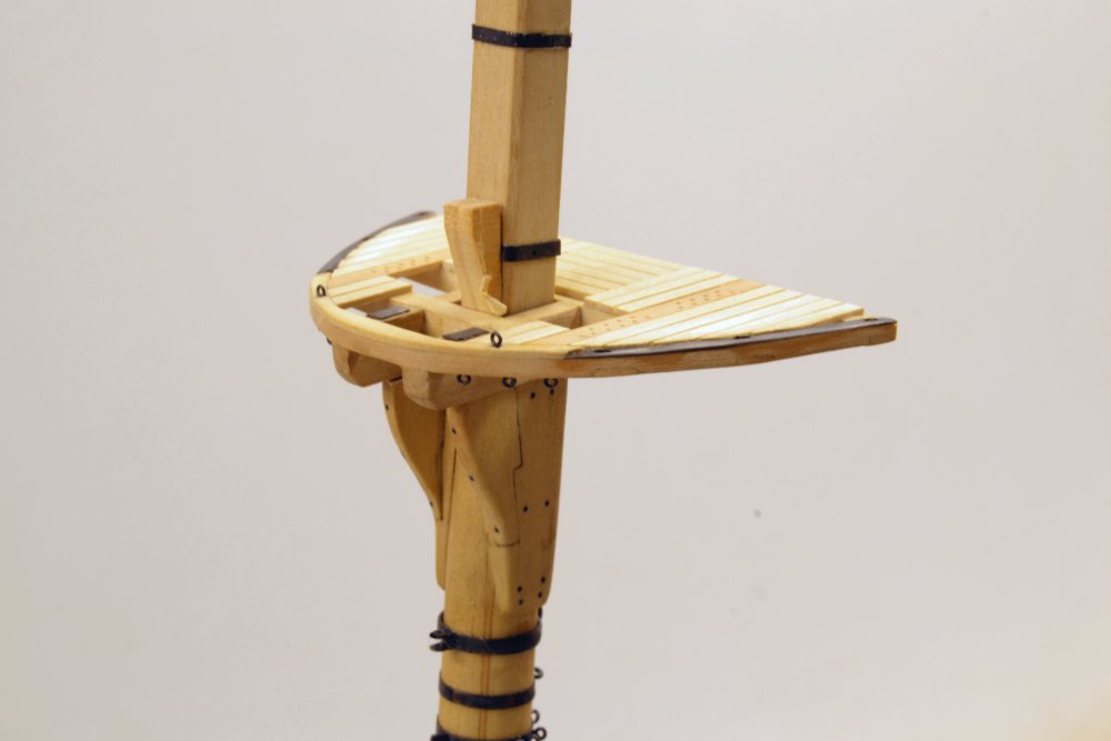
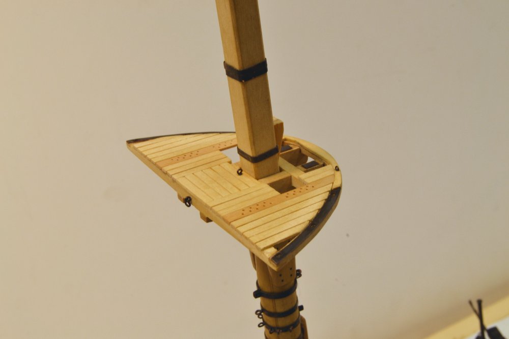
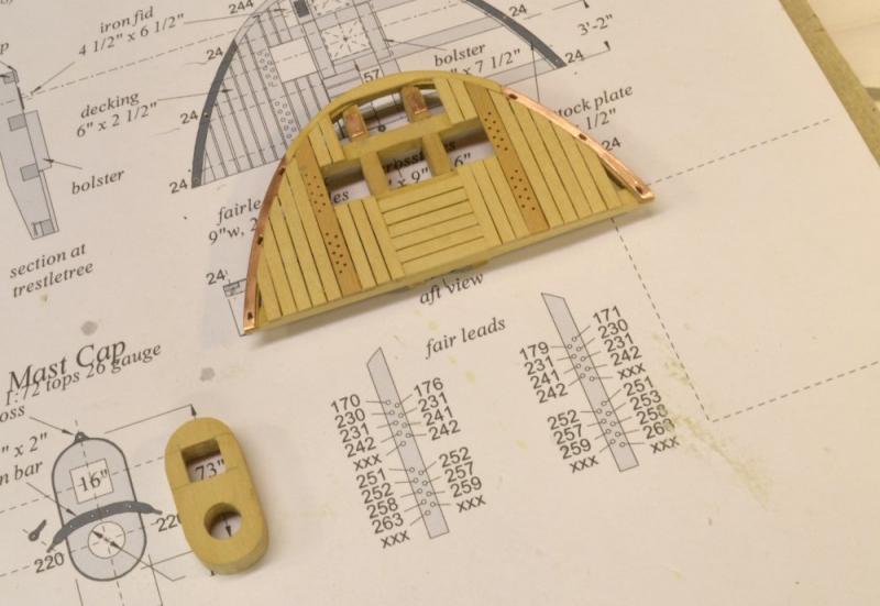
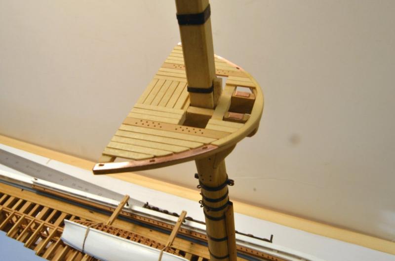
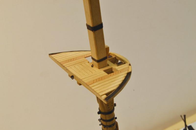
Young America - extreme clipper 1853 Part 191 – Decking the Fore Top Just when I was having fun with wood, more ironwork was needed. The first picture shows the addition of iron reinforcing for the rim in the area where the topmast shrouds will be positioned. The iron in this case is .010" copper, snipped to the shape of the top, glued on with CA. It was then trimmed to shape and polished, at least on the port side in the picture. The next picture shows the frame temporarily wedged on to the hounds. The iron rim caps have been drilled through the index points. The wooden rim cap that will cover the plank ends is being glued on in this picture. In the next picture, planking of the top is proceeding. Planks are 6" x 2 ½" thick. The 9" fairlead planks have been drilled and are being installed. The next picture shows the top with all planking installed. The holes in the rim have been converted to slots that will pass the deadeye straps. Also, the two iron fid plates on which the topmast fid will rest have been installed. Work on the fore mast cap has begun and is shown in the picture. The next picture shows the top again placed on the hounds. In the next picture the top has been trimmed out and the ironwork blackened. There are six eyebolts under the forward rim for the fore course bunt and leech lines. The two on the top of the rim will be hooked to the tackles of the upper topsail sheets. An interesting location for these. Belaying points for the added upper topsails may have been difficult to find on the crowded deck rails. The next picture shows the aft side. The eyebolt just aft of the mast will secure the main topgallant stay. There should be just sufficient space between this and the mast for the shroud collars. The shackled eyebolt on the aft crosstree will anchor the standing lift on the spencer gaff. There may need to be a bracket added forward of the topmast to secure an iron stay for the lower topsail yard that will be fixed at the cap. Last post before the holidays. All the best to everyone in this special season. Ed
- 3,618 replies
-
- 44
-
-
- young america
- clipper
- (and 1 more)
-
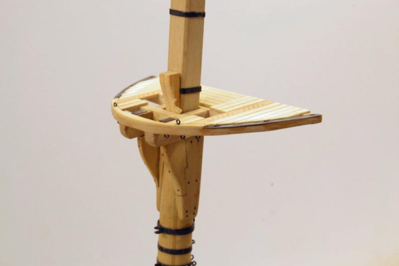
Hi Maury, On the spencer mast, aka trysail mast, aka spanker mast. I am no expert, but I looked through some of my usual sources. Campbell (China Tea Clippers) says these were used on large hooped masts where either the mast size would result in very large jaws on the boom or where the hoops would interfere with raising and lowering the sail, gaff or boom. So, the first question is do you need one on a craft of this size. If it shows on your drawing or other reference, that question may be answered. Campbell says they were either stepped on the deck or on a mast band. Underhill shows it stepped on a block on the deck on a generic drawing. Crothers shows it on a mast mounted stool on his Young America drawing, deck stepped on Challenge, and on some sort of ill-defined mast band/bracket on McKay's Lightning. I think you may take your pick without worry or over-thinking it. Of course, as druxey says, this was a different era - and all my references are for very large ships - and merchant ships at that. Hope this helps. Ed
- 525 replies
-
- 3
-
-
- anchor hoy
- hoy
- (and 1 more)