EdT
-
Posts
2,214 -
Joined
-
Last visited
Content Type
Profiles
Forums
Gallery
Events
Everything posted by EdT
-
Thanks, Druxey. That is pretty much what I am doing, except I tap it lightly. Works fine. Made a couple dozen 1.5mm size in an hour yesterday. Not a major issue. I still have to decide how far down in size to go with this. I'd like to be able to get down to about 5 1/4" rope (.025") to be able to do the standing lifts on the 6 topsail yards, but have not tried that size yet. There will definitely be a break point. On Frank.s (mahuna) suggestion, I ordered some small (1mm, .8mm, .6mm!, .4mm!!)Aluminum tube, which I will test, but I may not be able to get comfortable with the dissimilar metals issue. Anyway, there has been no shortage of suggestions. Thanks everyone. Ed
- 3,618 replies
-
- 3
-

-
- young america
- clipper
- (and 1 more)
-
Thanks for all the ideas for making the thimbles and hooks. I spent some time yesterday making and testing the steel male/female punch set that Frolich describes. For those without his book, the punch is in two parts, a female piece with a hole bored and a rounded cusp formed on the top around the hole. The second, male part, has a rod turned to fit the hole with a rounded fillet at its base. The thimble ring is slipped on the rod , the rod slipped into the hole and the piece tapped with a hammer to shape the flare. Also, he turns a groove into the perimeter before forming. His thimbles are made from 2mm diameter tube - according to the book. If I read correctly, he does not use thimbles with hooks - only a rope eye. He does not mention smaller thimbles. I think this is very reasonable, considering that at the smaller sizes the thimbles will be almost invisible. For the two sizes of thimbles that I expect to use ( 1mm and 1.5mm tube), the extended rods on the male parts of the die are very small - .5mm and .8mm, making this piece extremely fragile for use as a punch. Frolich's rod is larger at 1.2mm, which is a much more practical size for this method. The other problem with the device at this size is the feather edge on the female die. It wears quickly and when rounded imparts a recess in the thimble where a smooth flare should be. In retrospect, when I ask myself what problem I am trying to solve, I feel quite happy with my simple punch where the biggest problem is the very small pieces falling off the anvil, bouncing on to the floor and becoming lost. Actually, handling the small parts is the only real issue. I think a larger steel plate - maybe I'll work at the cast iron table on my full size circular saw - will solve the one problem I am having with these. So, it never hurts to explore new ideas. Today i expect to get back to my masts - while the snow piles up outside. Ed
- 3,618 replies
-
- 8
-
-
- young america
- clipper
- (and 1 more)
-
I checked out the tool Frolisch describes for making thimbles. It is a two part die with each piece shaped to form a flare. One part has a spindle to fit the hole in the thimble blank, the other a hole to fit the spindle. with the thimble place on the spindle flares on both sides are formed when the die is closed under pressure. The "female" part of the die must have a very fine edge at the end. Presumably separate dies would be needed for different sizes. Yes, the lathe could also be used, with the added benefit of being permanently centered if a two part die is used. The mill would have to be centered in this case, unless a flat surface is used to do one side at a time. Ed
- 3,618 replies
-
- 6
-
-
- young america
- clipper
- (and 1 more)
-
Thank you all for the comments and likes - and for the suggestions. Frank, I have ordered Aluminum tube in sizes from .4 to 1 mm diameter and I will give it a try. I have some concern about galvanic corrosion with the brass hooks. The anodic differential between these materials is borderline with a controlled environment and in the danger zone with "normal" conditions. My preference is to stay with brass pieces. I may be able to "grey" them with heat. Wefalck, that is an impressive device. An alternative I have considered is the use the milling machine as a press and I expect to try that. I am not excited about tinning pieces of this size, but I will give Frolich's book a look. I had not thought to look at it for this. Also, I must look into the galvanizing - or zinc coating - of these parts in the 1850s. I believe the thimbles were straight zinc and the hooks would be iron. Thanks for the tips. Laman, I did a fair amount of photo-etching on Naiad, on the plate knees, capstan rings and on parts of the stove. I do not see it as a means to make thimbles since they are not flat. On the hooks, these need to be threaded through the thimbles so would have to be made with a break. Also they are rounded in shape and rather thick for photo-etching. As far as the photo-etch process itself, while very useful for some things, it is not something I am anxious to return to, but thanks for the suggestion. So, thanks for these comments - got me thinking and doing some followup. Ed
- 3,618 replies
-
- 8
-
-
- young america
- clipper
- (and 1 more)
-
Thanks for the input, Frank. I will look into the Aluminum tubing. There is a small amount of wire cable on the model, but it is a long way off and I have not begun to play with that yet. I think the hooks will be OK black. Ed
- 3,618 replies
-
- 6
-
-
- young america
- clipper
- (and 1 more)
-
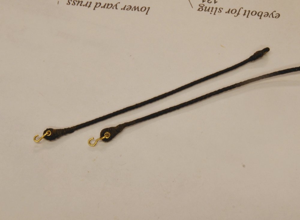
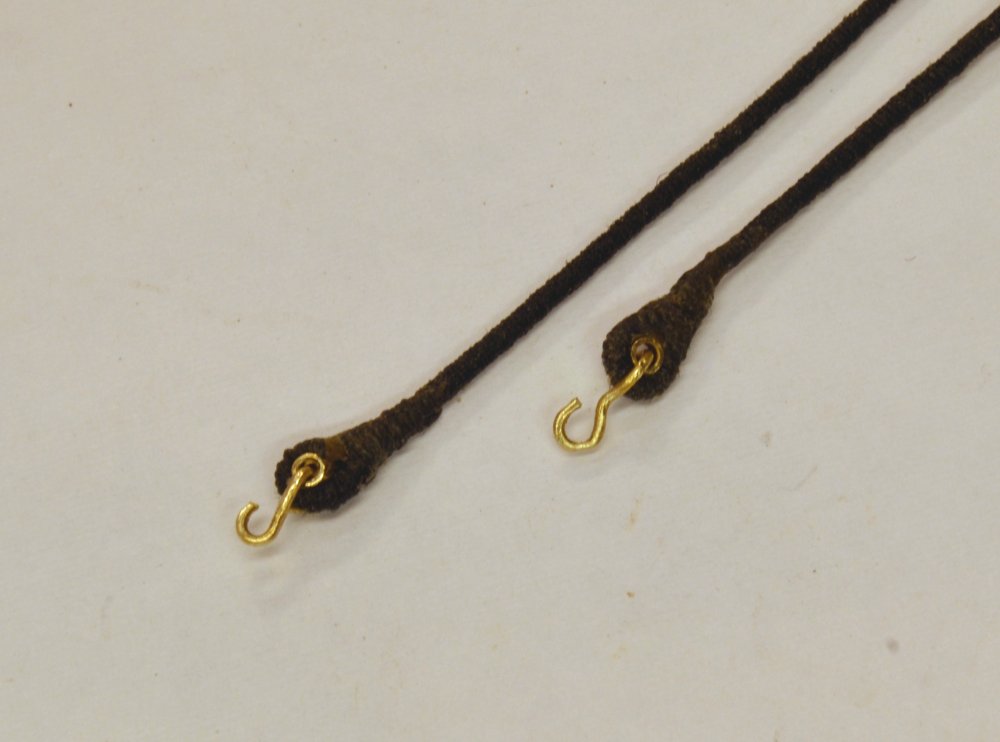
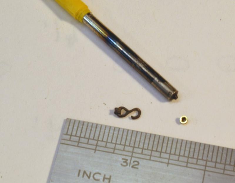
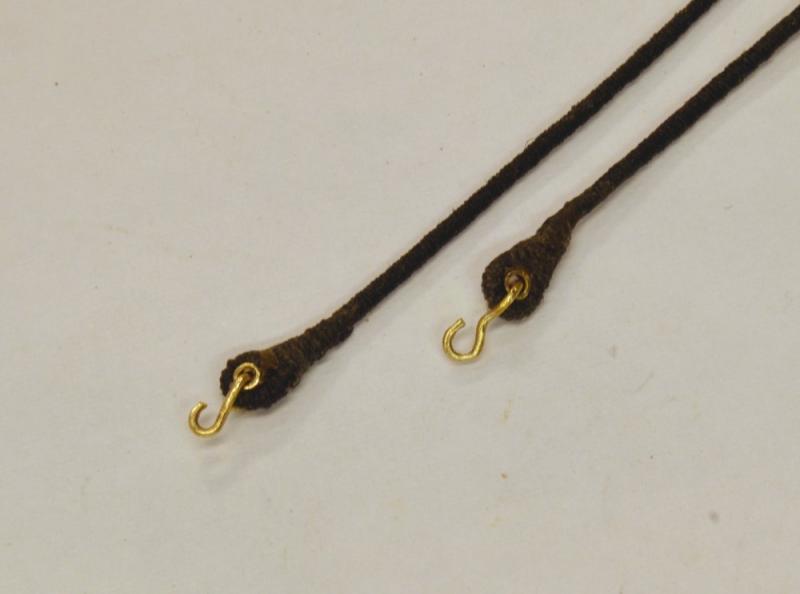
Young America - extreme clipper 1853 Part 193 – First Rigging Work It has been quite a long time, relatively speaking, since the last posted update. I have been very busy, but with little progress that is visible on the model. Decisions and documentation for the rigging have been major, time consuming efforts. Because rigging was undergoing a transition at the time – from rope to wire or chain, to the use of iron fittings like shackles, and many other things, there are choices to be made. Some require a modeling solution before they can be adopted. The idea of arbitrary choices may seem odd, but I am using more than half a dozen sources, old and new, they all differ and few are date based or specific as to merchant vs. navy. It may seem surprising, but the first rigging to be done will be the topmast futtock shrouds. I plan to install these on the masts after the tops have been fixed and before the masts are stepped. I have sidelined that work pending resolution of the futtock shroud design. I number of issues have to be decided. The first was rope vs. iron bar. I have decided on rope. Then there is material – linen vs. cotton. I would like to use linen on the standing rigging that will be modeled taut. I have been making a lot of sample rope using the six sizes of thread in my inventory to decide how to make each size. Then there are questions on fastenings: hooks, shackles or lashed eyes. I have tentatively decided on hooks with thimbles at the deadeye straps and lashed eyes at the mast eyebolts. I have just a few pictures illustrating some of the test work. None of this is finished product. The first picture shows a blackened hook and thimble, an unblackened thimble made from thin-wall, 1mm, brass tube, and the tool used to shape the thimble flares. The flaring tool was turned from a bit of drill rod, then hardened. It will probably be replaced with a better shape. I may or may not pre-fabricate the hooks and thimbles. Thimbles at this time were becoming more heart shaped and open at the throat. Although Longridge describes a method, I could not do it at this size. Also, thimbles were not black – another issue. I also have to decide how far down in rope size to use thimbles. There are some advantages, to pre-fabbing the hooked thimbles but more test work is needed. The next picture shows an alternate approach where the eye is formed first, the thimble inserted, flared in place, the area over the splice served and the serving used to tighten the throat. The picture shows two sizes of thimble 1mm and 1.5mm – another decision. A length of rope, ~6" in this case, was served first. The eye splice was made by looping the served line and gluing it below the throat. When dry, the excess was trimmed off the splice and the thimble inserted. The splice was then served with thinned glue to strengthen the joint and tighten the throat. The hooks were then formed in the eye. The last picture shows a closer view. I like this method but the metal parts will need to be blackened first and that raises issues in forming the hooks. The shapes of the splices will get better. These test pieces were made in the space of about an hour, so I had to be careful with the unhardened glue joints. And so it goes… Ed

- 3,618 replies
-
- 31
-
-
- young america
- clipper
- (and 1 more)
-
Gerald, I have looked at the tool descriptions on your website a number of times. The craftsmanship is exquisite. You did this in 9 weeks?! I am even more impressed with the design of the tools. For me, tool design is often a trial and error affair, so I am very impressed with the confidence and skill needed to desigh, then construct these tools and then have them work. Bravo. Ed
- 281 replies
-
- 5
-
-
- falls of clyde
- tanker
- (and 2 more)
-
Nice work, Micheal. The stanchions look fantastic. Why not replace them all! It never occurred to me to use old drill bits to make milling cutters. Great idea. I am still eagerly awaiting the results of that paint job on the side. Did I miss it? Ed ps. I had another thought on a tailstock center when there is interference with the tool holder. As you may have seen I use tube in a tailstock chuck for supporting square wood turnings, but for brass wire perhaps a length of drill rod with a hole bored in the end could be used. Its diameter would have to be large enough to keep it rigid.
- 749 replies
-
- 6
-
-
- albertic
- ocean liner
- (and 2 more)
-
ancre Chebece 1750 by Jeronimo - FINISHED
EdT replied to Jeronimo's topic in - Build logs for subjects built 1501 - 1750
A lot of progress, Karl. Ed -
I continue to admire your work on this fantastic project, Nils. Ed
- 2,625 replies
-
- 5
-
-
- kaiser wilhelm der grosse
- passenger steamer
- (and 1 more)
-
Bob, in looking at your earlier note I see that you edited the text. I cannot understand the altered question relating to wale height etc. Was this question superseded by your last note? Are we good, or do you need some further clarification? There is no wale line on Drawing 5, which is an internal view. The 23" distance from the planksheer to the wale is consistent on Drawings 1, 3, and 4. All appears correct to me, but... if you have questions.... Ed
- 3,618 replies
-
- 3
-
-
- young america
- clipper
- (and 1 more)
-
Although the drawings are pretty accurate, always refer to the List. Sleep tight. Ed
- 3,618 replies
-
- 4
-
-
- young america
- clipper
- (and 1 more)
-
ancre Chebece 1750 by Jeronimo - FINISHED
EdT replied to Jeronimo's topic in - Build logs for subjects built 1501 - 1750
Karl, Good to see you starting a new series. What is the model at the beginning? Surely you have not completed this since December. Ed -
Hi Bob, I did not include the thickness of the planksheer rail in the calculation because the line of the planksheer is taken at the underside of the rail, so everything is measured downward from there. The planksheer is 6" deep. I hope I have not mentioned 7" anywhere that would cause confusion. Both the text and the List of Dimensions show 6". Metal to wood joints can be an issue. I have found that working the epoxy into the bolt hole helps, but the normal adhesion issues still apply. Slower curing epoxies may be better. Perhaps application early in the cure cycle improves adhesion. I haven't a clue. In any case, longer cure times is a benefit for the other reasons mentioned above. I use only uncoated wire so when it is used for fittings or in other exposed applications it may be blackened - also for soldering. If you are functioning at 230 am, you have my admiration. My effectiveness - at just about anything - ceases after dinner at 7. Ed
- 3,618 replies
-
- 7
-
-
- young america
- clipper
- (and 1 more)
-
An additional comment, Bob. I should have mentioned, that the line of the main deck at the side is the most important to have correct. This line runs parallel to the planksheer, which is defined on the builder's offsets. This line defines the underside of the planksheer rail and the upper face of the main deck waterway that rests on it. You will see from the list of dimensions that the main deck waterway is 11" deep. Since this waterway rests on the 12" deep main deck beams at the side, the top of the main deck clamps should be 23" (11+12) below the planksheer. This relationship holds over most of the length, but forward of about Frame line T the depth of the waterway begins to reduce to about 9" at the stem. The red line on drawing 5 reflects this relationship with the planksheer line that is shown on drawings 3 and 4. Its a nasty little complication that you need to keep in mind. This change in waterway depth is referenced on pp160-61 and p 185. You will see that installing the planksheer rail later, as a practical matter, its height will be set by the waterway installed earlier. If this is too confusing, let me know. My best advice is to set the deck clamps to the red lines on drawing 5, as indicated in the book. Martin, I again passed over your note. Bob's questions always get my juices flowing. I am familiar with Dawson's painting of Taeping and Ariel as well as others, including the one from above the deck that you mention. When I was working in the West end in 1969-71, the painting was on display in a the Bond Street Gallery that carried his work. I had two prints hanging in our home for years, Constituion and Java and one of an unnamed (or forgotten) Spanish ship. I've always loved his work. Ed
- 3,618 replies
-
- 6
-
-
- young america
- clipper
- (and 1 more)
-
Hi Bob, If by the master you mistakenly mean me, I will try to answer. Unfortunately, the heights of decks were not included on the original builders offsets. Crothers used a height of about 7'9" from top of beam to top of beam on the centerline. I adopted his dimensions, measured from his 1:96 drawing. The comparable heights at the side will vary due to the constant round up radius of the deck beams and the varying width of the hull. The red lines on Drawing 5 define the heights at the side with reasonable accuracy. I believe I recommended using these lines to measure deck heights at the side. Due to drawing issues in creating long fair lines in bezier curves where there are many points, the fairness of the deck lines at the side (or on the centerline) is not perfect, but close enough for the purpose. Using battens and a few points along the side will yield fair lines well within acceptable accuracy. The heights should then be made equal on the opposite side. A constant differential in deck lines at the side would have saved me many hours of drafting work and might help you as well, but alas, it would be incorrect - at least given the assumptions on the centerline heights. If you want to do an exercise, measure heights at the side from cross-section drawings where the beam round up is shown. You might want to verify heights at the center before using these. Hopefully they should match the red lines on Drawing 5. I do not recall doing this level of checking. Maybe I'll try a few. Ed
- 3,618 replies
-
- 9
-
-
- young america
- clipper
- (and 1 more)
-
Thank you very much, Tony, for this information. I have visited the model store at Chatham and was aware of their service, but was not aware of a similar service for the Science Museum models. I am sure this will be most helpful to modelers who may wish to visit. Many thanks, Ed
- 3,618 replies
-
- 6
-
-
- young america
- clipper
- (and 1 more)
-
As always, thanks for the generous comments and for the likes. I'm a bit behind in the followups but I will respond to some of the comments. Martin, your comments bring back memories. I guess I can understand, at least on a logical level, the need of the Science Museum to focus on Science, even though the loss of that exhibit saddens me. One question: Who is NR? I had understood that George Campbell did the text drawings and large drawings for Anatomy. Was there another hand at work? Alan, technology marches on. I well understand the nostalgia for things past, but the engineer in me is drawn to new methods. I did all the many drawings for my first model ( a picture above) with the instruments you describe and did the drawings for Naiad and Young America using two different CAD programs. Both methods have their challenges, believe me. While there is little question that the manual skills necessary to produce a good, much less perfect, drawing by hand are not essential to the use of CAD, there are other challenges. As one example, for one who used a lot more eraser than lead, there are some obvious advantages in making corrections. But to me the real advantage of CAD to the ship modeler is precision. The ability to produce a one-pixel width pattern line with mathematical precision has great advantages in small scale work This has yet to be widely appreciated where there is a pencil-dominated tradition, but the change will happen and the models will get better. Bob, the model looks fantastic. I am delighted to see your work. You are right to be vigilant on alignment issues. This is a long, gracefully shaped hull that will show imperfection. Misalignment will also drive you crazy when you go to work on the decks. You make an excellent point on the five minute epoxy. Longer working time would be an advantage. I have since moved to a 30-minute product for that reason. As far as peening of copper wire epoxied bolts, I do not recall doing that and will need to look at the book. I believe all I did on those was to clip off and file off the ends and excess glue. Where copper wire was used a "nails" without glue, peening was definitely done as they were hammered in - for example on the iron strapping and on fastening of Naiad's iron knees. I also would endorse your decision to get the deck clamps in early. Like Mike Y, I would love to see you do a build log - as you already know. Roger, I love your suggestion on the microwave. Brilliant. Ed
- 3,618 replies
-
- 5
-
-
- young america
- clipper
- (and 1 more)
-
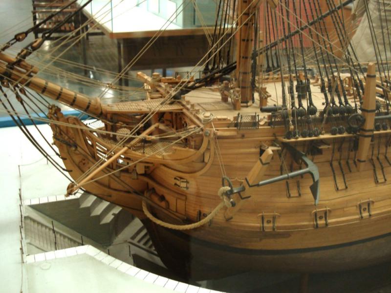
I know they are not in the NMM collection at Chatham Dockyard, but would like to see them safe in that world class facility there someday. I can think of less acceptable fates. Another picture showing my half-sized copycat attempt. Any lack of family resemblance is not for want of trying. Ed

- 3,618 replies
-
- 18
-
-
- young america
- clipper
- (and 1 more)
-
Martin, Somehow, perhaps in my usual careless haste, I passed over your post. My apologies for not immediately responding. Anyway, reading it this morning certainly brightened my day. Your comments are far too generous, but I do appreciate the acknowledgement for sharing the how-to details. I like doing that, but it is also a way to give back to the craft and the community that have been so helpful to me. I get the same satisfaction out of doing the books, as do the other authors I know and the publisher. Thank you. The closing of the ship model section at the Science Museum is regrettable to say the least. It was clearly giving way to other displays over the last years of my visits. I spent many rainy, and even snowy Sunday afternoons there during many business trips in the 80's, usually with a notebook and pencil in the days before concealable camera phones. My sons - and perhaps to a lesser degree - the female family members enjoyed visits as well when we lived there. We made the last visit in 2005 and I did manage to sneak in a view pics. One is attached. I thought you might enjoy it. If anyone knows where the model ended up, I'd love to know. Ed
- 3,618 replies
-
- 12
-
-
- young america
- clipper
- (and 1 more)
-
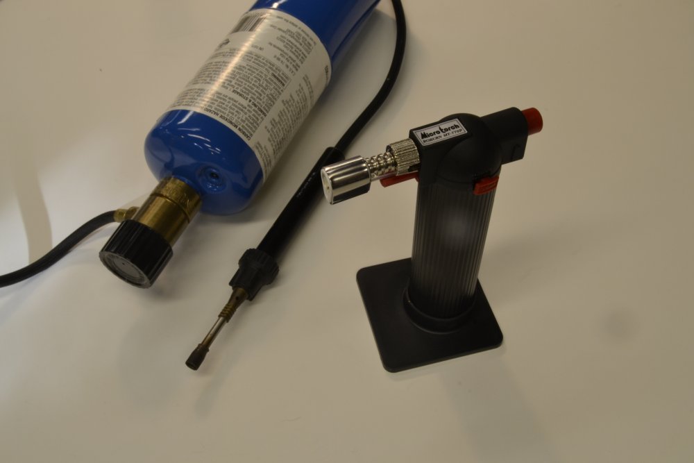
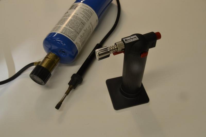
Hello Micheal, It is true that you get very fast, high heat with O2. My problem is often too much heat on small wire parts, so of course it all depends on the work. Below is a picture of my old and new torches. The one on the left attached to the propane cylinder is no longer available from what I can determine. The popular, rechargeable, butane self-starter on the right is very common. It is widely sold for kitchen use as well as for soldering. It is very convenient to use. Ed
- 749 replies
-
- 8
-
-
- albertic
- ocean liner
- (and 2 more)
-
Looking good, Micheal. Looks like you are ready for anything with the soldering set ups. I have a similar, perhaps the identical, oxy-propane torch. I am surprised you need an oxy-enriched flame temp for these small parts. I hardly ever use mine, in favor of the small propane torch (that is no longer available, I'm afraid.) I recently started using the Burnz-o-matic micro torch - a self-igniting refillable, butane torch that is very convenient to use with plenty of heat for the small silver-solder joints that I make. With O2 at $8 a cylinder, and very short life, I avoid using it except when I have to. Ed
- 749 replies
-
- 6
-
-
- albertic
- ocean liner
- (and 2 more)
-
Wayne, thank you for the link to the Science Museum picture of Cutty Sark. I had not seen it before and have never seen the model, although I made at least 15-20 visits to the model section of the Science Museum in the 1980's. Since many of these were to make notes on the Longridge Victory model. I know I would not have missed it, so I can only assume it was not on display in that period. Of course, all that is gone now. Greg, your comment got me paging back through the Longridge Cutty Sark book. Like Anatomy, it is a fascinating read. Some points that caught my eye: In the 1933 preface he states that in trying to find a book giving "the anatomical view" of a sailing ship, he had it on good authority that "no such book existed in the English language". Then, interestingly, "Although models of the Cutty Sark are so many, and varied, that as a prototype, she is a somewhat hackneyed subject, I decided to build a model of her....". Already hackneyed in 1933? On Scale: The model is 1/4" to the foot. A big model of a 200' ship, but as I think about it, not a lot larger than the 1:72 model of the 239' Young America. His comments on addresses in London where items may be purchased are fun to read - things like silk and linen thread, tinned copper wire, tools, etc. He made actual screwed shackles from 26 gauge copper wire, hand filed the milling cutter teeth to groove the waterways, served all the footropes and stirrups, silver plated thimbles made from copper sheet, and it goes on. Using a cyanide bath to darken metal makes me less hateful of the products we all use (and love to hate) today. Although for some reason I overlooked his model design for the windlass, I was pleased (and relieved) that it looks a lot like mine - and like mine his is virtually invisible under the forecastle. The drawings for the book were done by Harold Underhill - a name that I am sure we all know. The book contains many pictures of the ship and of the model in progress. His comments on rigging sequence - leaving lower ratlines until all running rigging is done, setting up main and topmast stays before the lanyard on the lower shrouds on next forward masts, etc. But the big one is to make all the rigging with its parts, etc. an tuck it await in storage before any is erected on the model. Who has the self-control for that? A fascinating book - and worth the search it will take to find it. Ed
- 3,618 replies
-
- 8
-
-
- young america
- clipper
- (and 1 more)
-
Very nice work on an very interesting model, Maury. Bravo. I appreciate the cutting of the carlings in place - not easy. Ed
- 525 replies
-
- 2
-
-
- anchor hoy
- hoy
- (and 1 more)