EdT
-
Posts
2,213 -
Joined
-
Last visited
Content Type
Profiles
Forums
Gallery
Events
Everything posted by EdT
-
I am quite sure these were the builders models. They are in the Smithsonian collection. I have other pictures of them. Ed
- 3,618 replies
-
- 3
-

-
- young america
- clipper
- (and 1 more)
-
Rob, thanks for posting the photo from the Smithsonian. I am familiar with this - the original builders half model - but have not seen it in person. Its good to know it is on exhibit. Ed
- 3,618 replies
-
- 5
-
-
- young america
- clipper
- (and 1 more)
-
Ah, now that is one beautiful chainplate. Bravo, Frank. Ed
- 649 replies
-
- 6
-
-
- dunbrody
- famine ship
- (and 2 more)
-
Ah, silver-bearing soft solder and resistance soldering - good tips. Ed
- 649 replies
-
- 5
-
-
- dunbrody
- famine ship
- (and 2 more)
-
Thank you all for the posts and likes. Allan, you're giving me a complex. Micheal, nice to see you back online. Ed
- 3,618 replies
-
- 4
-
-
- young america
- clipper
- (and 1 more)
-
Glad to hear you weathered the storm, Dave. For some reason I remembered that you lived in Lumberton and thought of you while watching the news. All the best. Ed
- 962 replies
-
- 7
-
-
- sovereign of the seas
- ship of the line
- (and 1 more)
-
At the risk of continually repeating myself, your work is outstanding and I regret not being at the conference to see it. The deadeye design with the tight, confined, flat strop precludes slipping the deadeye into place after soldering - an interesting problem. Like Druxey, I wonder about the soft solder, but given that the soldered joint will be in sheer rather than tension, should be OK. There is nothing worse than having a chainplate break when tensioning shrouds. I tend to over-design for strength and would probably look for a silver-soldered solution. Otherwise, I think your method will be fine and will look great. I think if I were doing this and expected high stress from lower shrouds, I would consider making the deadeye in two pieces with an internal joint parallel to the faces. These could then be glued together over the finished, silver-soldered, blackened strap. Probably would drill the deadeyes after - perhaps in a jig, but the assembly may clamp into the rotary mill table for drilling by that method. Just an idea that would need to be tested. I also wondered about deforming the chain plate in a vise, or with strong pliers, or even hammering with a flat punch, rather than twisting. I used the vise method on YA's chainplates, which have the same connecting end shape. Ed
- 649 replies
-
- 6
-
-
- dunbrody
- famine ship
- (and 2 more)
-
Another little known historical fact: When Orville and his sister Katherine Wright sailed to France to join their brother Wilbur who had been in negotiations with the French government for the sale of the Wright brothers "flyer" in early 1909, they sailed on the Kaiser Wilhelm der Grosse. Sorry, but the plane went over earlier with Wilbur on the Campania. Ed
- 2,625 replies
-
- 9
-
-
- kaiser wilhelm der grosse
- passenger steamer
- (and 1 more)
-
I am fascinated, Nils. Beautiful. Ed
- 2,625 replies
-
- 5
-
-
- kaiser wilhelm der grosse
- passenger steamer
- (and 1 more)
-
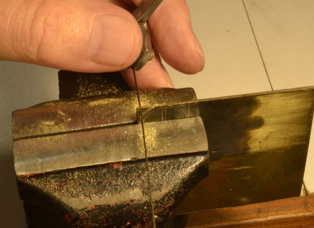
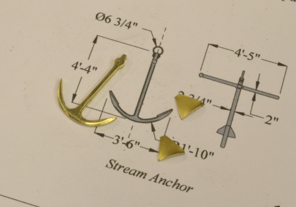
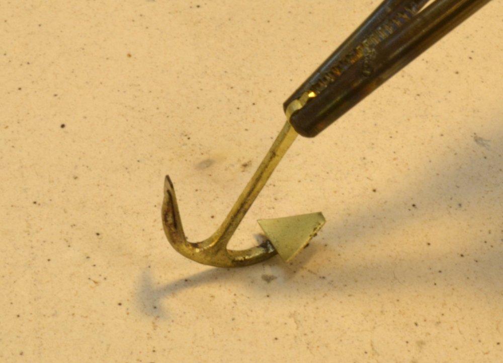
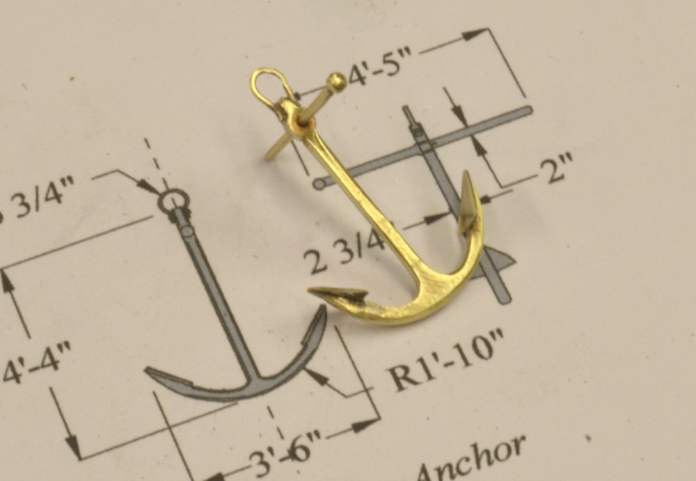
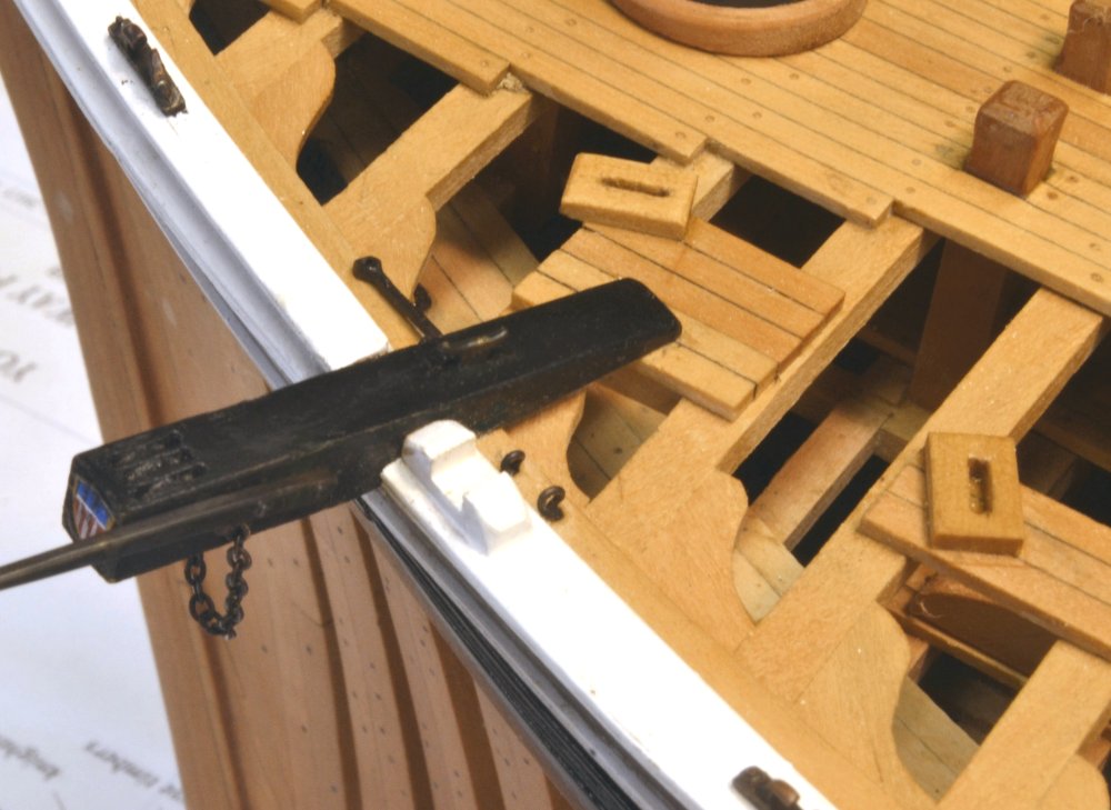
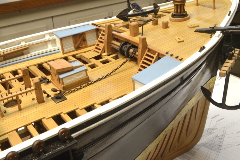
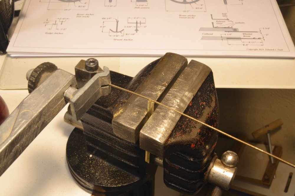
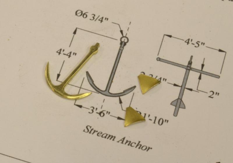
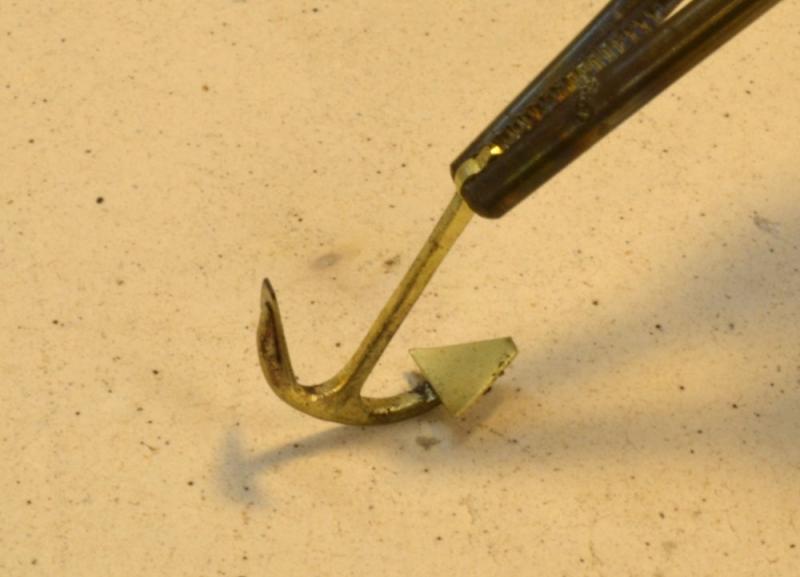
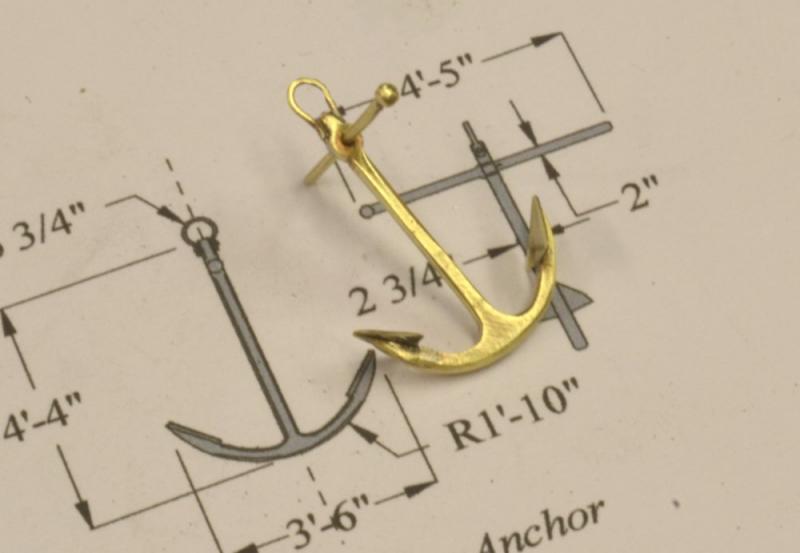
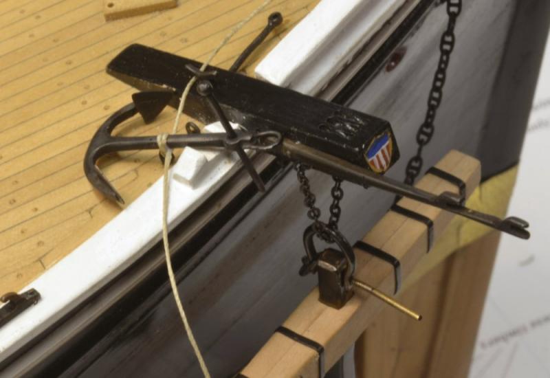
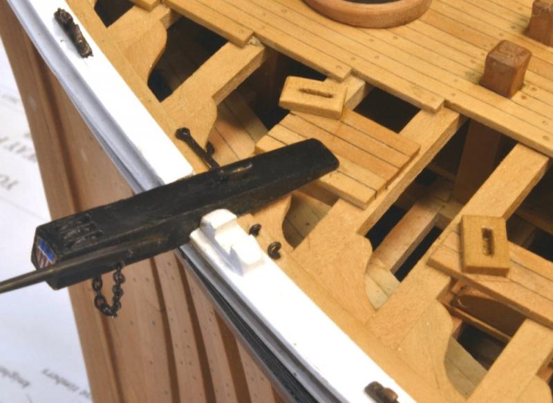
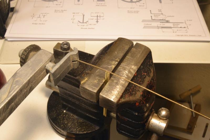
Young America - extreme clipper 1853 Part 178 – Stream Anchor Ships like Young America carried several anchors. The two bower anchors for the model were covered in an earlier post. One stream anchor, one-third the size of the bowers was also modeled. These anchors were used for warping or sometimes for short mooring in very calm waters and winds. Obviously these would be much easier to handle than the large heavy bowers. There were other smaller types but I settled on just the three. The stream anchor was cut in one piece from a .032" thick plate of hard brass. The outline was drawn on a blackened portion of the plate and cut with a jewelers saw as shown below. The larger anchors were made in two pieces and soldered to save material and for the straightness of the bar shank, but with the smaller anchor this method made sense. The next picture shows the anchor and two oversized flukes cut from a thinner sheet. These were oversized realizing the clamping for soldering would not be precise. They would be filed to the final size after soldering. The soldering set upis shown below. The next picture shows the fabricated anchor. The stock and the shackle on this anchor are soldered on. The last picture shows the anchor being secured on the starboard side in the vacated space used by the suspended bower anchor. With all anchors stored, this small anchor would probably have been lashed to the shank of one of the bowers. Next chore: Making and fitting the supports for the swinging booms, that is, the fore lower studding sail booms. Ed
- 3,618 replies
-
- 33
-
-
- young america
- clipper
- (and 1 more)
-
Hi Druxey, I'm a bit behind in responding. I rounded the wood stock slightly. Have seen many different examples. Ed
- 3,618 replies
-
- 3
-
-
- young america
- clipper
- (and 1 more)
-
Thank you Nils, Johann and all the recent likes. Ed
- 3,618 replies
-
- 4
-
-
- young america
- clipper
- (and 1 more)
-
Thank you everyone for your very generous comments and for all the likes. They keep raising the bar for me. No, E&T, making chain is above my pay grade. The purchased, studded, copper chain used is particularly nice, 10 lpi from Caldercraft in Cornwall. Allan, I'm overwhelmed. Thank you. No, there is no home for the model, except to say that one must either be found or one of us will need to move out. She is going to be big. Fortunately, that problem is a couple years off - at least. Thank you, Greg. Likes are very welcome but comments are always better - and especially questions. The last tasks to complete the work needed for Volume II is finished except for a dozen or so of those pesky belaying pins. Stream Anchor and swinging boom iron work were completed this week and will be posted soon. Thanks, again, Ed
- 3,618 replies
-
- 13
-
-
- young america
- clipper
- (and 1 more)
-
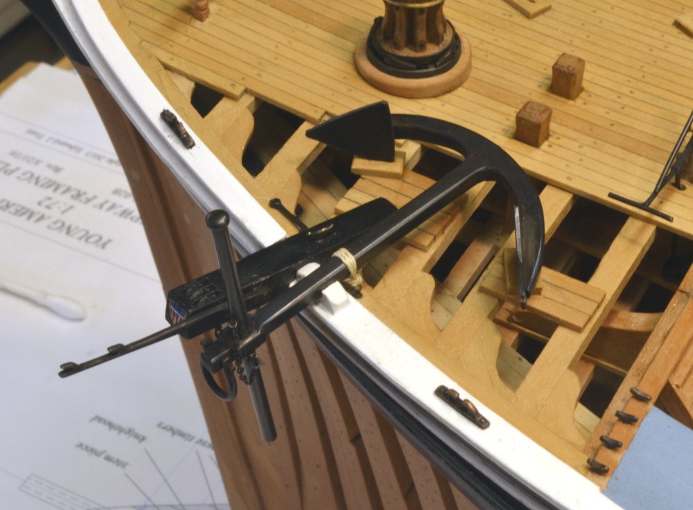
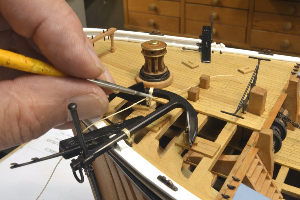
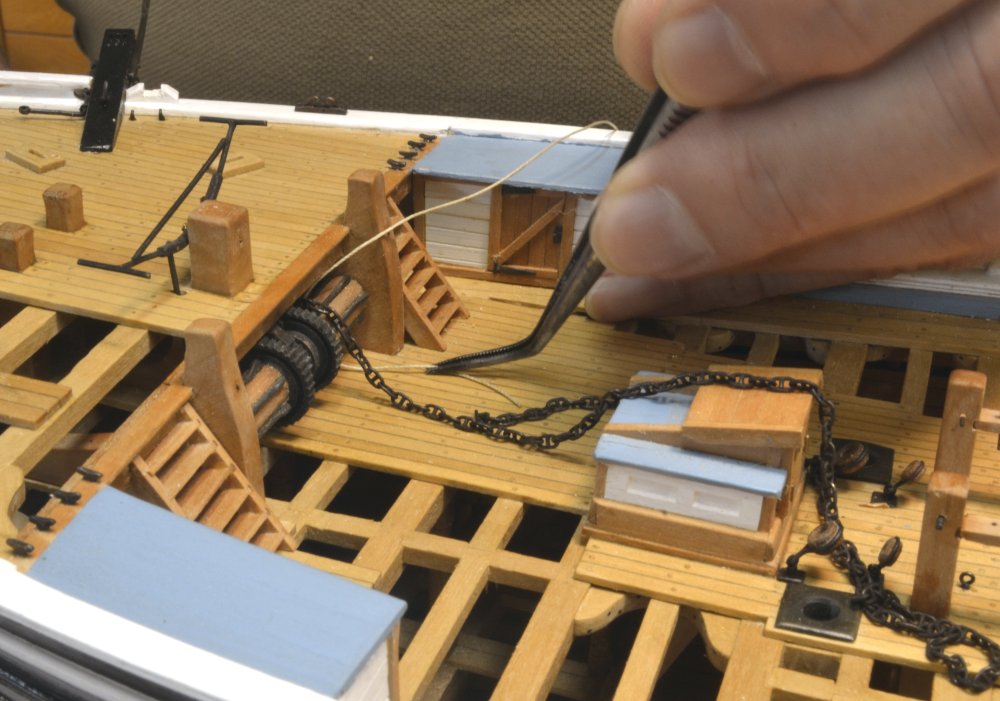
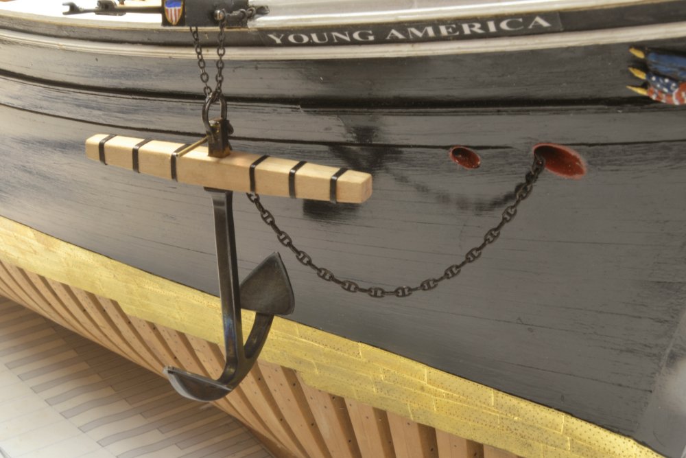
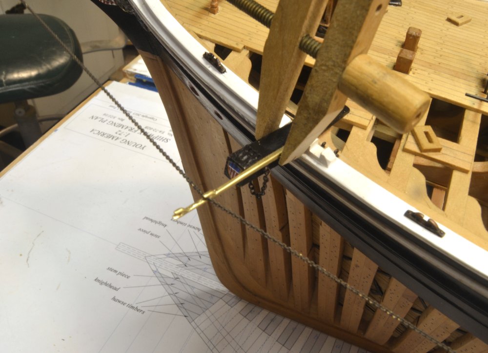
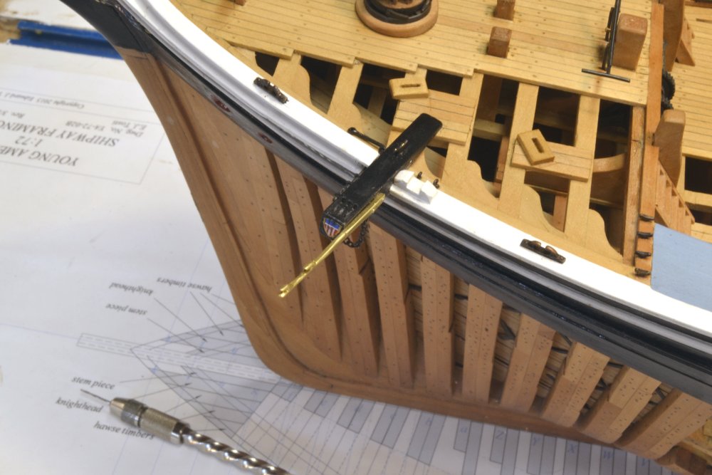
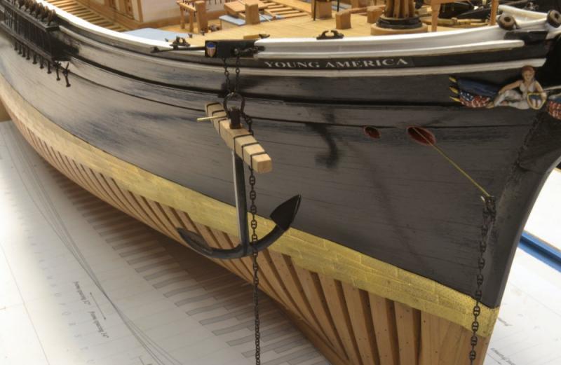
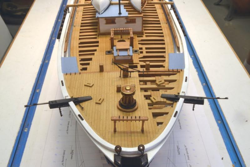
Young America - extreme clipper 1853 Part 177 – Mounting Bower Anchors The plan has been to suspend the wood stocked bower anchor from the starboard cathead as depicted in the picture of the ship docked at San Francisco. The iron stock anchor is to be placed in its storage position on the port side of the forecastle. The first picture shows mounting chocks and two securing eyebolts for anchor storage. The next picture shows the iron-stocked bower anchor in position, secured by a rope lashing to eyebolts on the margin plank. The positioning and means of securing the anchors is somewhat speculative, but typical. In the next picture, eyebolts have been installed below the arms and a lashing is being touched with thinned white glue to secure the seizing. In the next picture, the starboard anchor has been suspended from the trip chain on the cathead. The cable chain is also threaded on to the shackle. This shackle has a threaded bolt which will be trimmed to size later. A hooked brass rod can be seen inserted from above the windlass through the hawse hole to fish the chain under the forecastle. The next picture shows the chain pulled through over the top of the windlass. The string shown in the picture has been threaded over the windlass so the chain can be taken over for another turn. In the next picture the chain has been wound over the windlass and dropped through the chain tube to the hold. The last picture shows the suspended anchor ready for release. The shackle bolt remains untrimmed at this stage. The next step will be to make and install the smaller stream anchor. Ed


- 3,618 replies
-
- 49
-
-
- young america
- clipper
- (and 1 more)
-
I continue to be speechless over the tooling and methods - to say nothing of the scale. Ed
- 281 replies
-
- 1
-
-
- falls of clyde
- tanker
- (and 2 more)
-
Thank you all. Good advice, Maury - climate permitting of course. Rob, everything after Volume I before starting masts and rigging will be included in Volume II - with of, course, all the drawings for that work. Only a few tasks now remain to get to that point. Stream anchor, mounting the anchors and chain, swinging boom brackets are about it. If you have Vol I you will be aware that the level of descriptions in the book are far more complete than the overviews given here in the build log. Ed
- 3,618 replies
-
- 7
-
-
- young america
- clipper
- (and 1 more)
-
Thanks, Guys. Now, if I can just keep from snagging my shirt cuff on them. No special holders Frank - just the vise shown in the pictures. I may have used a small hand vise shown in an earlier post to finish the cleats. The pieces were not too difficult to make. I suppose they could have been milled to make very precise shapes, but I am trying to use hand methods where feasible in the interests of non-machinist future readers of the book and also because the originals were probably manually forged and would have that look. Ed
- 3,618 replies
-
- 5
-
-
- young america
- clipper
- (and 1 more)
-
Fantastic, Frank. I really envy you having the real thing as a guide. Ed
- 649 replies
-
- 8
-
-
- dunbrody
- famine ship
- (and 2 more)
-
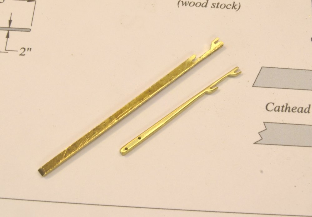
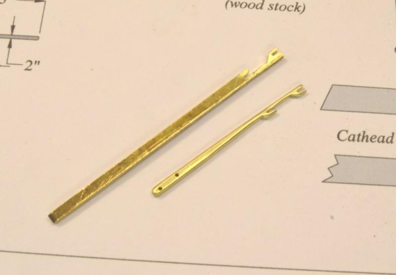
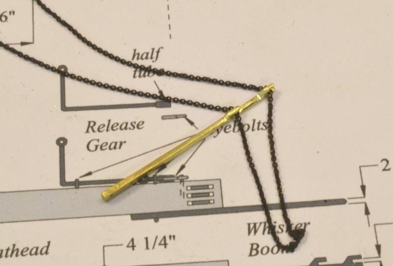
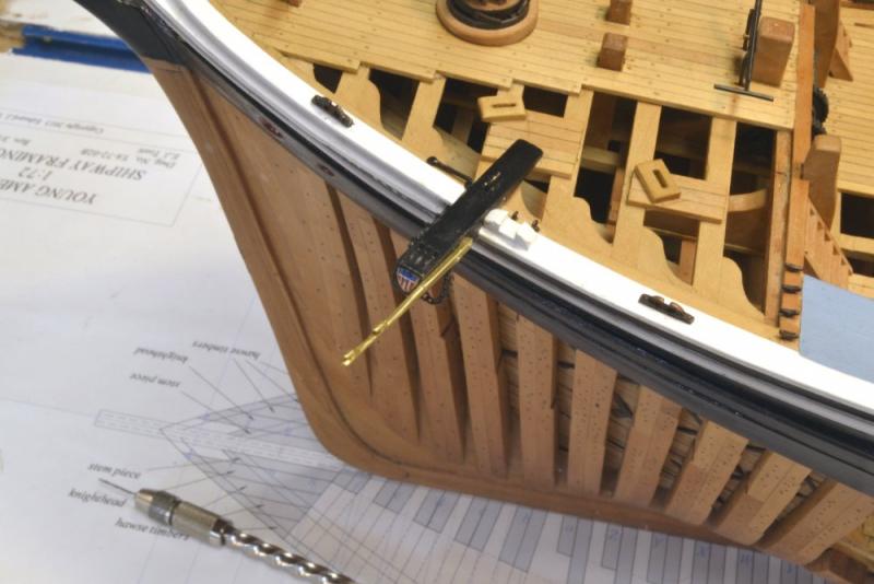
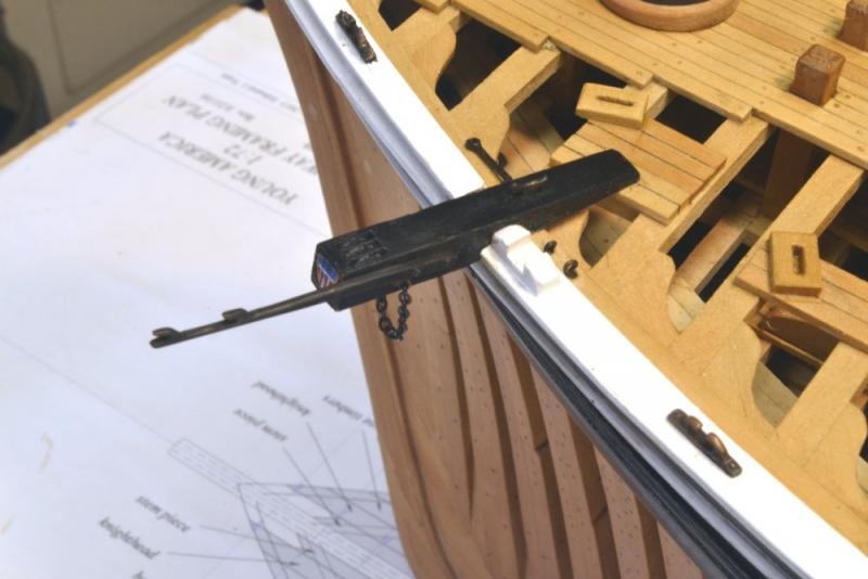
Young America - extreme clipper 1853 Part 176 – Whisker Booms After a couple weeks on my favorite beach – one passed by Young America on her last fateful voyage – I have now returned refreshed and ready for the fall modeling campaign. The whisker booms were completed just before we left. Whisker booms were iron extensions to the catheads that served as spreaders for the chain jibboom and flying jibboom guys. The first picture shows the installation of these fragile-looking members. The whiskers extend about 5 feet from the ends of the catheads and are bolted to the after sides. Each has formed cleats on the top face through which will pass the chain guys. The whisker booms were made from hard brass plate and were shaped by hand methods – sawing and filing. In the next picture a jeweler's saw with a fairly wide blade is being used to cut the inner line of the end cleat on the pair of booms. Apart from these initial cuts, each boom was shaped individually. The next picture shows one finished boom and one in progress. To be sure these would smoothly pass the chain guys they were tested as shown below with some of the correct-size chain. In the next picture the port boom is held in place with a clamp while the run of the chain guy is being checked. The guys will obviously be installed later when the bowsprit is installed and rigged. The next picture shows the port boom temporarily bolted to the cathead. The bolts were silver-soldered into the booms before blackening, then rounded off and cut to length. The bolts were then CA glued into drilled holes in the cathead. The last picture shows the finished boom on the port side. Ed

- 3,618 replies
-
- 33
-
-
- young america
- clipper
- (and 1 more)
-
HMS Naiad 1797 by albert - FINISHED - 1/48
EdT replied to albert's topic in - Build logs for subjects built 1751 - 1800
Bravo, Albert. Beautiful work as always. Ed -
That's what I am planning, Joel - excess on the end panels that will overlap the side panels on the inside. Should only be a small overlap line. The main purpose is dust protection and ease of access for construction. Should work out fine. Thanks for the input. Ed
- 3,618 replies
-
- 2
-
-
- young america
- clipper
- (and 1 more)
-
Thanks, everyone. jbshan, I intend to curve the paper to blend at the corners, but remember, the sides must be removable. Thanks. Ed
- 3,618 replies
-
- 1
-
-
- young america
- clipper
- (and 1 more)
-
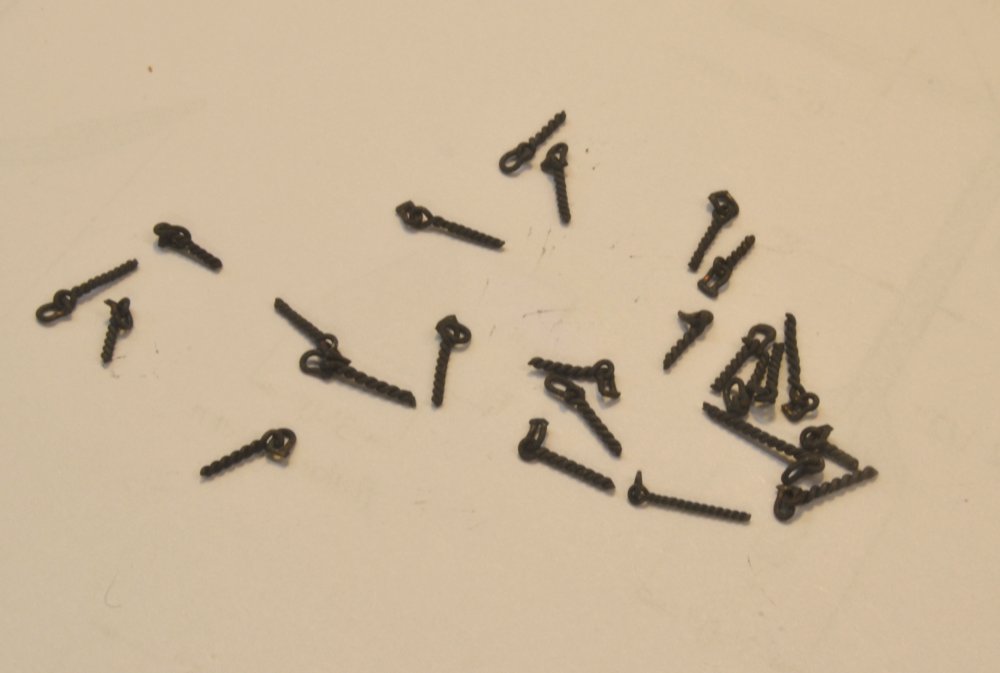
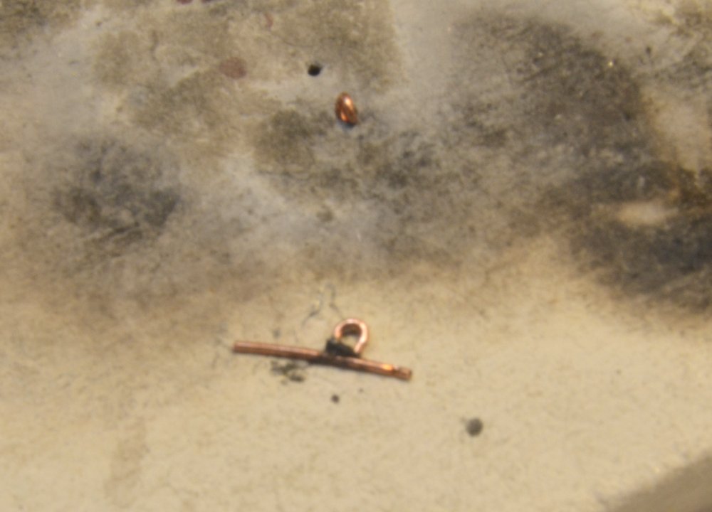
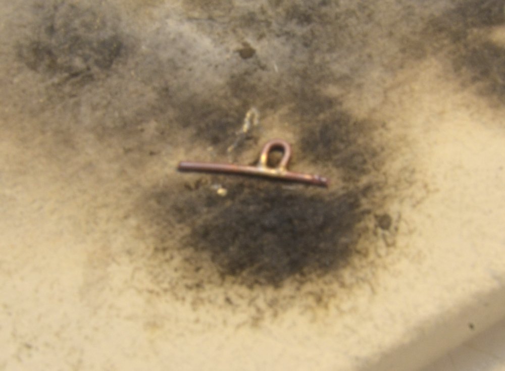
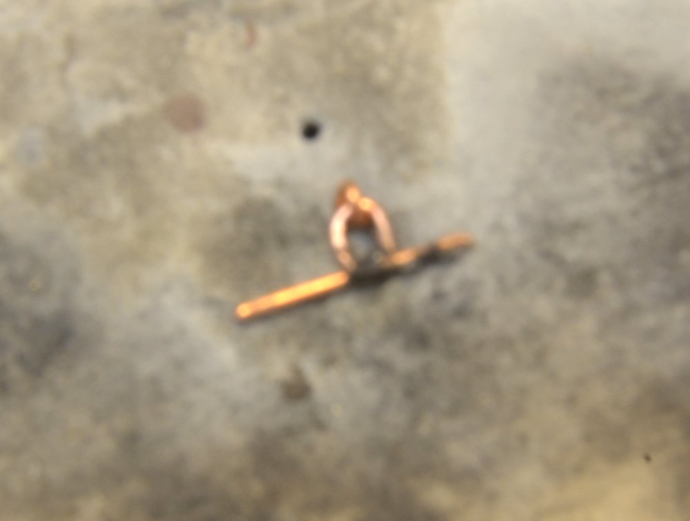
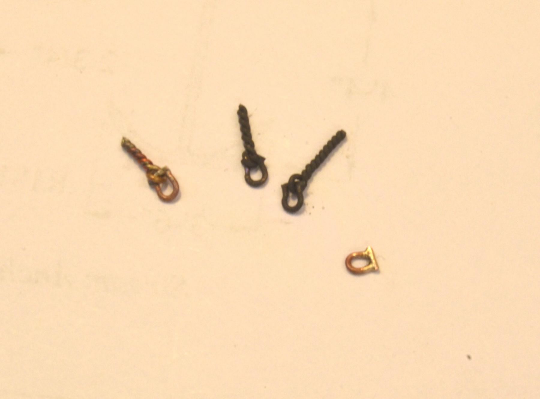
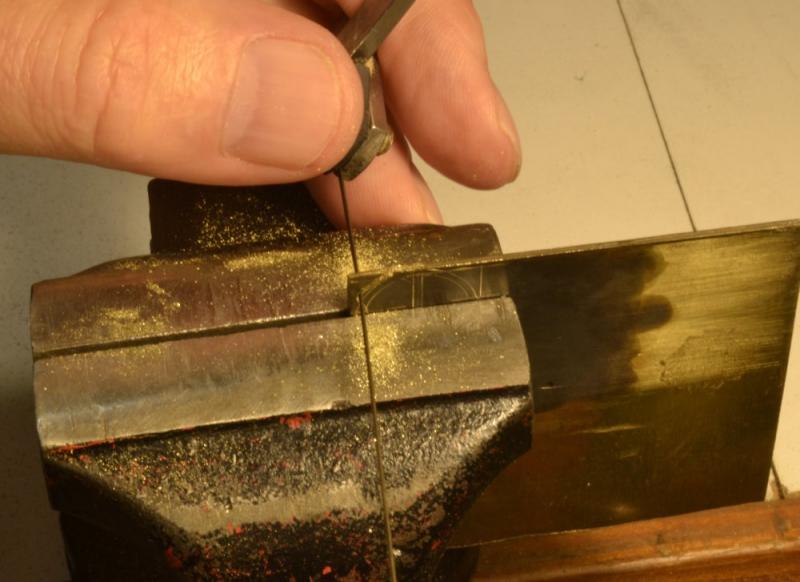
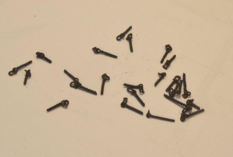
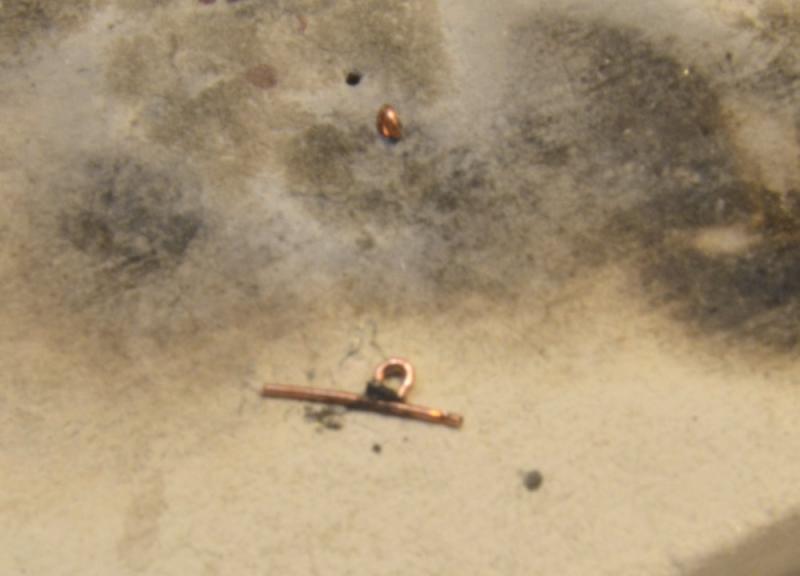
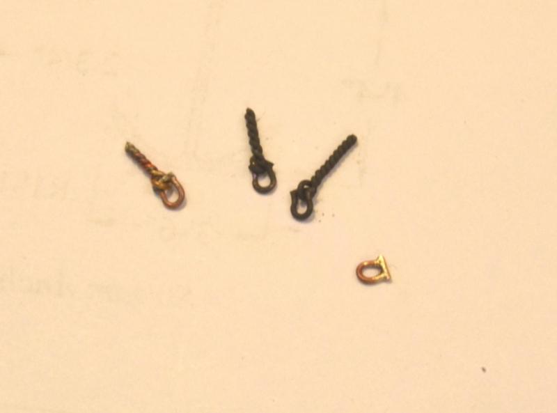
Young America - extreme clipper 1853 Part 175 – Shackles Since I will be away for the next couple weeks, I thought I would cram in one more post before leaving – especially since it relates closely to the last post. There will be many shackles like those described below in Young America's rigging – 3 dozen or more on the deck and hull, plus many more aloft on yard bands, connecting chains and wire to rope, etc. Shackles consist of U-shaped iron yokes with screwed bolts threaded into the ends. They replaced ring bolts, seized lashings and other connectors. Easy removal of the screwed bolt allowed connections and disconnections to be made easily. Several shackled eyebolts are shown below. These will eventually be installed in the deck, rails, or hull by the method described in the last part – but not until later after the lines have been spliced on at the workbench. The next picture shows the two parts of a shackle about to be silver-soldered. The two pieces are 24 gauge copper wire – same gauge as the eyebolt. Copper-phosphorus paste has been applied at the joints. The configuration of the pieces is intended to simulate the horseshoe shape with a straight bolt at the bottom. The picture also shows an eyebolt embedded in the soldering block ready for attachment of its shackle – not the one shown. The next picture shows the soldered shackle before trimming the bolt ends. There will be relatively few of these standalone shackles, so this was for demo only. The next picture (apologies for bad focus) shows the soldering setup for an eyebolt-attached shackle. The embedded eyebolt must be kept clear of the solder paste so the parts will swing freely. After soldering, the shackle must be rotated so its bolt passes through the eyebolt allowing the rope or other line to connect to the horseshoe loop. This rotation has been done on the pieces in the last picture. The loops on these shackles at 1:72 are about 6" (.08" actual) diameter. Next topic: Whisker booms. Ed


- 3,618 replies
-
- 37
-
-
- young america
- clipper
- (and 1 more)