EdT
-
Posts
2,214 -
Joined
-
Last visited
Content Type
Profiles
Forums
Gallery
Events
Everything posted by EdT
-
Hi Gary, Congratulations on reaching this point. She looks great. No one likes rework but it seems to be an essential part of the job - for most of us at any rate. Just one more skill to master. You won't regret doing it. Ed
-
THE 74-GUN SHIP by Jeronimo
EdT replied to Jeronimo's topic in - Build logs for subjects built 1751 - 1800
Karl, I finally got a chance to run through this work from the beginning. Simply beautiful. Have you really accomplished all this since since last May. Fantastic! Ed -
Frank, the use of the milled jigs for accurate assembly is brilliant - and the precision shows. Ed
- 649 replies
-
- 7
-

-
- dunbrody
- famine ship
- (and 2 more)
-
Thank you, Frank - and others for the likes. I confess that a few did take flight. Ed
- 3,618 replies
-
- 3
-
-
- young america
- clipper
- (and 1 more)
-
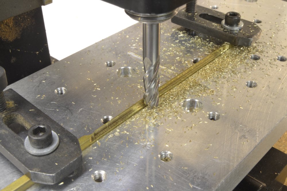
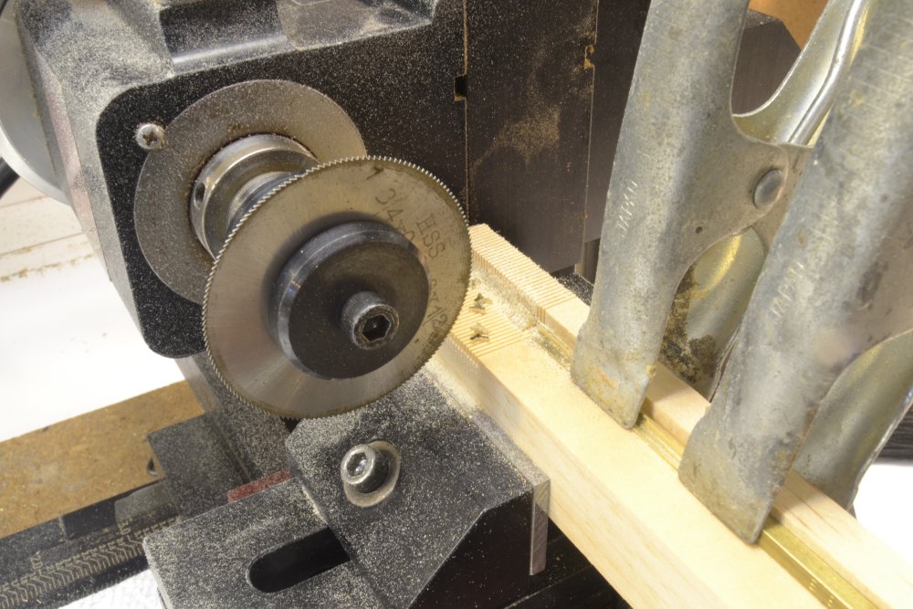
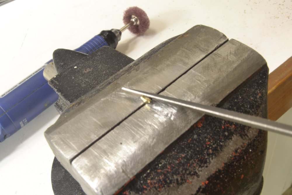
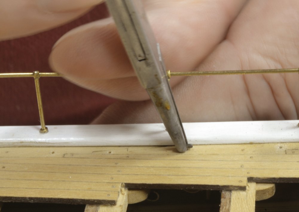
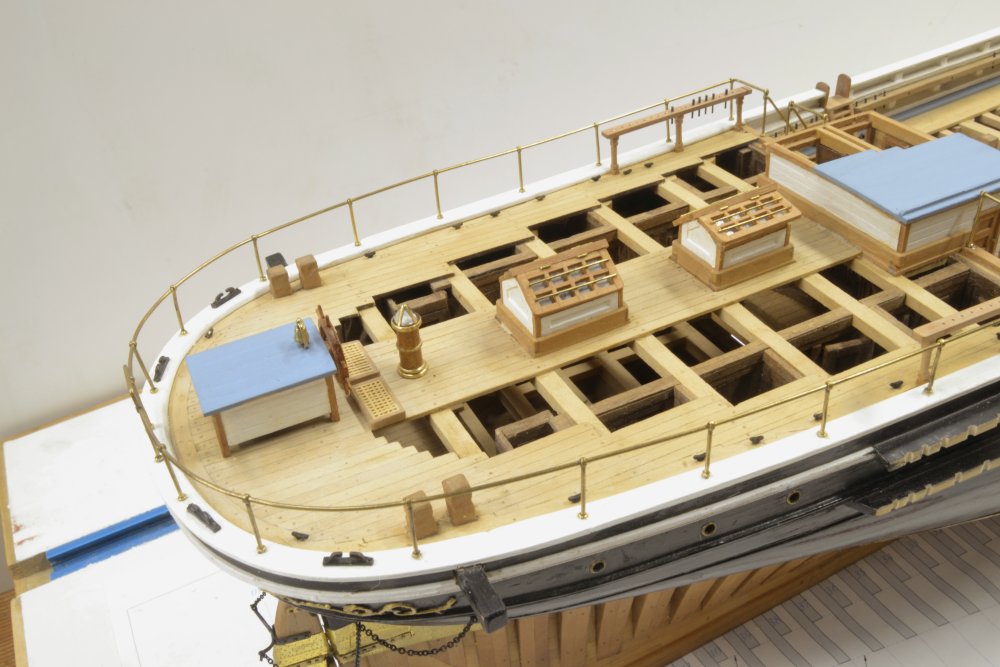
Young America - extreme clipper 1853 Part 170 – Rigging Cleats 1 Most of the work to be done before embarking on masts and rigging is to install a variety of rigging connection points to the decks and hull. There are two sizes of cleats on the model. They are being made by two different methods. I will start first with the smaller 9" long cleats. There are a few dozen of these, too many and too small for me to consider fabricating them in pieces, so they were sliced off the milled brass section shown in the first photo. In the next picture a 9" square rod (1/8" actual) has been aligned on the milling plate, clamped, and is having a shallow, concave groove milled in the top. Next, the piece was inverted and the sides milled to form the rough fina,l stepped, "T" shape. The piece was then rounded and refined by filing before slicing off the cleats. The slicing is being done as shown below using a thin slotting saw blade and a sacrificial wood fence. This method allows the small pieces to be cut to a precise thickness – in this case about 3" (.030" actual). The individual cleats were then rounded by filing and polished as shown below. The brass cleats were then blackened and finally inserted in drilled holes with a small drop of CA to keep them in place – shown below. The next picture shows the small cleats installed on the poop deck. These will eventually secure some of the lighter mizzen rigging. The next picture shows cleats on the forecastle. These are duplicated on the port side and will belay the jib sheets. In the next part, the larger 12" cleats for the lower sails' sheets and tacks will be described. Ed

- 3,618 replies
-
- 42
-
-
- young america
- clipper
- (and 1 more)
-
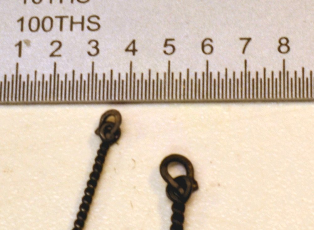
Further to my lamentations on shackle problems: Sorry to dwell on this but is has become an issue in the rigging sequence and therefore a puzzle as to how much of this to include in the "pre-rigging" content of Vol II vs. Vol III. Some may find this interesting. My plan has been to get all these connections installed in the hull and deck in Vol II then start Vol III with mastmaking. So.... Here is a picture of two eyebolts with shackles. These were made by fitting the horseshoe of the shackle through the eyebolt then silver-soldering wire across the ends of the horseshoe to simulate a screwed bolt. This may also be done by making the shackle then spinning the eyebolt over it. In either case the work must be done before installing the eyebolt in the deck or whatever. Ideally all the deck eyebolts and the drilling involved should be done before other rigging gets in the way and perhaps blocks should be strapped to the shackle before installing. Rigging specifications, drafting and planning needed. This is how I'm spending my summer. Ed
- 3,618 replies
-
- 27
-
-
- young america
- clipper
- (and 1 more)
-
Thanks, everyone. I had a feeling I would be hearing from you on this latest post, Druxey. Did you know you were that predictable? I suppose risk aversion is a relative trait, but there is no doubt that bringing a torch into proximity of a wooden ship model is not to be recommended. Having said that, my main concern was incineration of the chain, which on the bench could be protected with a heat sink. With the long rudder horns, I knew I could keep the small flame directed away from the hull - with concentration. Still . . . The problem of making the small iron shackles used widely during the period of this ship is a problem that concerned me for some time. Rope seizings are a lot simpler and able to be installed later. Soldered assembly of the small shackles seems unavoidable and that means installing them on eyebolts, yardarm lugs, chains,etc. in advance of assembly on wood parts. This has invited some odd sequencing of steps that I am still sorting out and that I suspect will begin to appear in some upcoming posts. Shackles were the last connection to be made in actual practice. It seems with my method, they will have to be the first. This problem hadn't entered my mind when the rudder was made. Ed
- 3,618 replies
-
- 8
-
-
- young america
- clipper
- (and 1 more)
-
Big milestone, Gary. She looks terrific. Ed
-
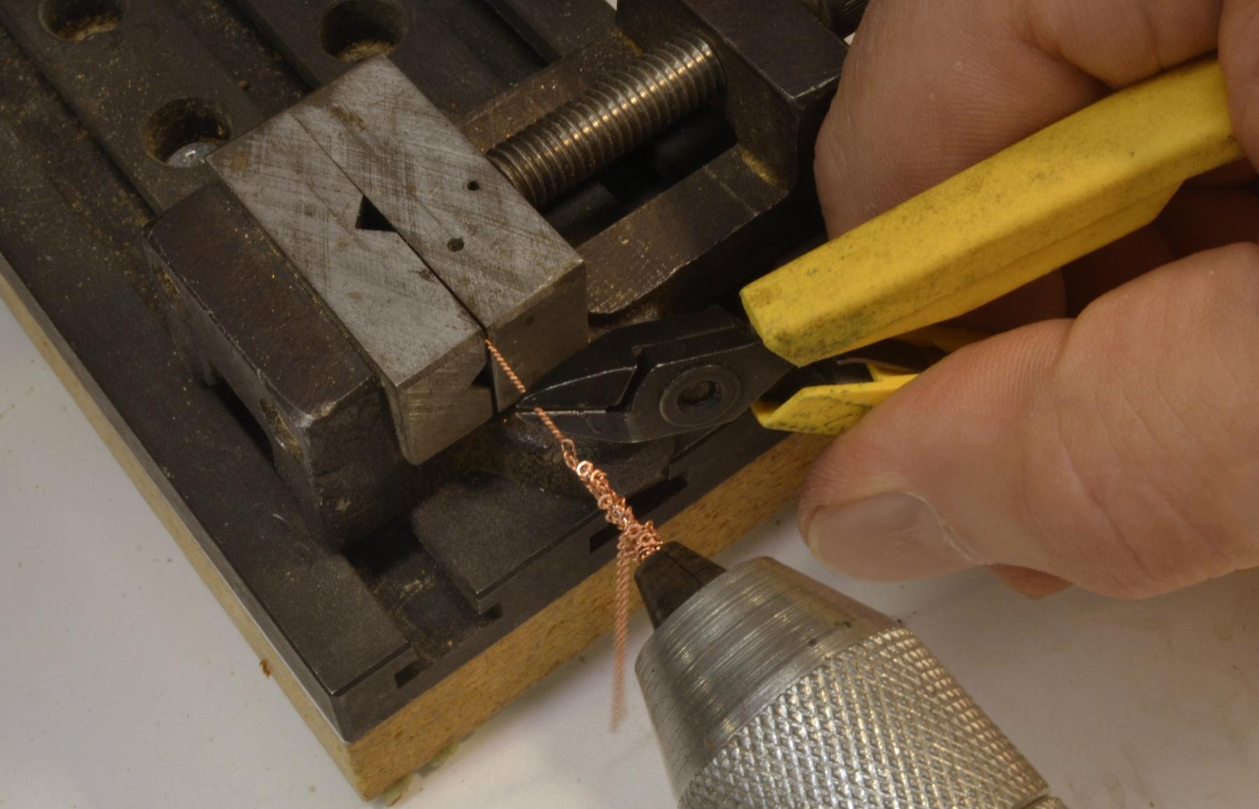
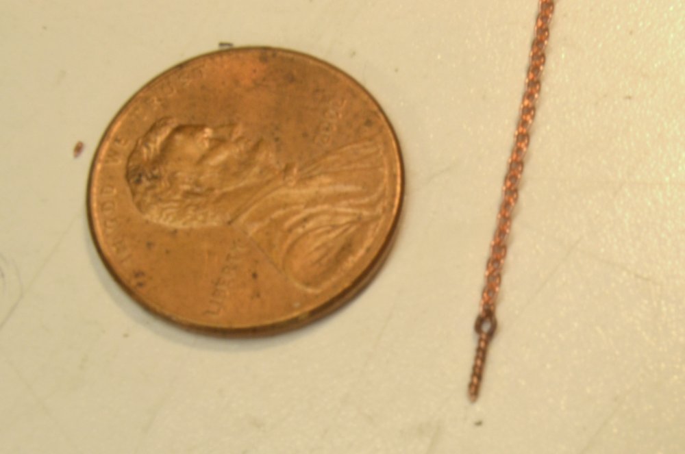
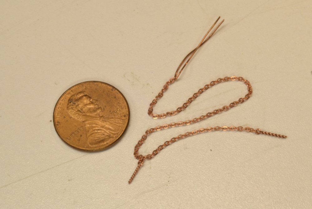
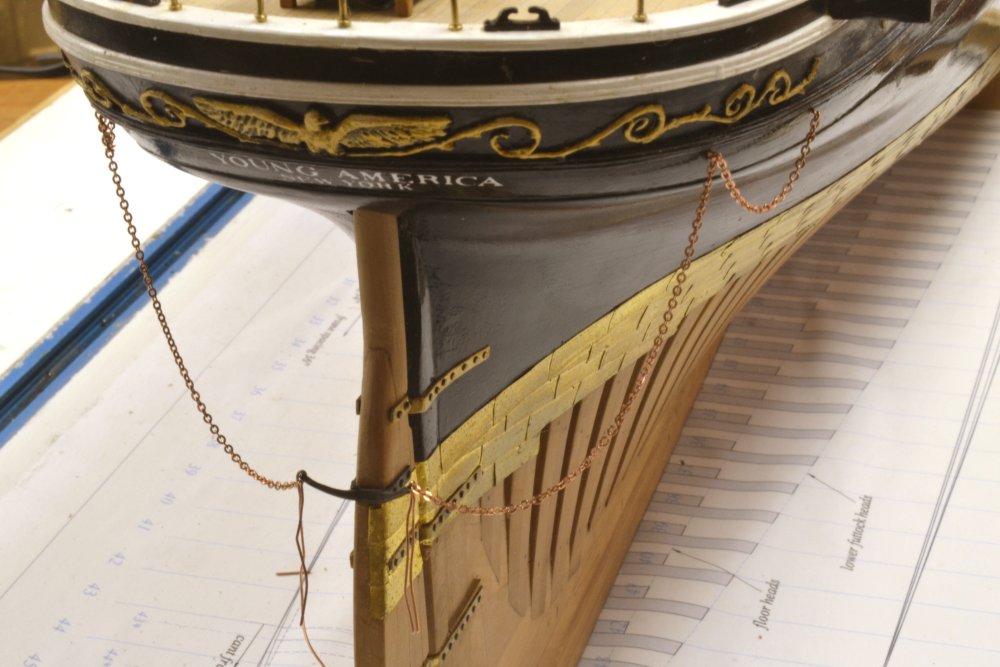
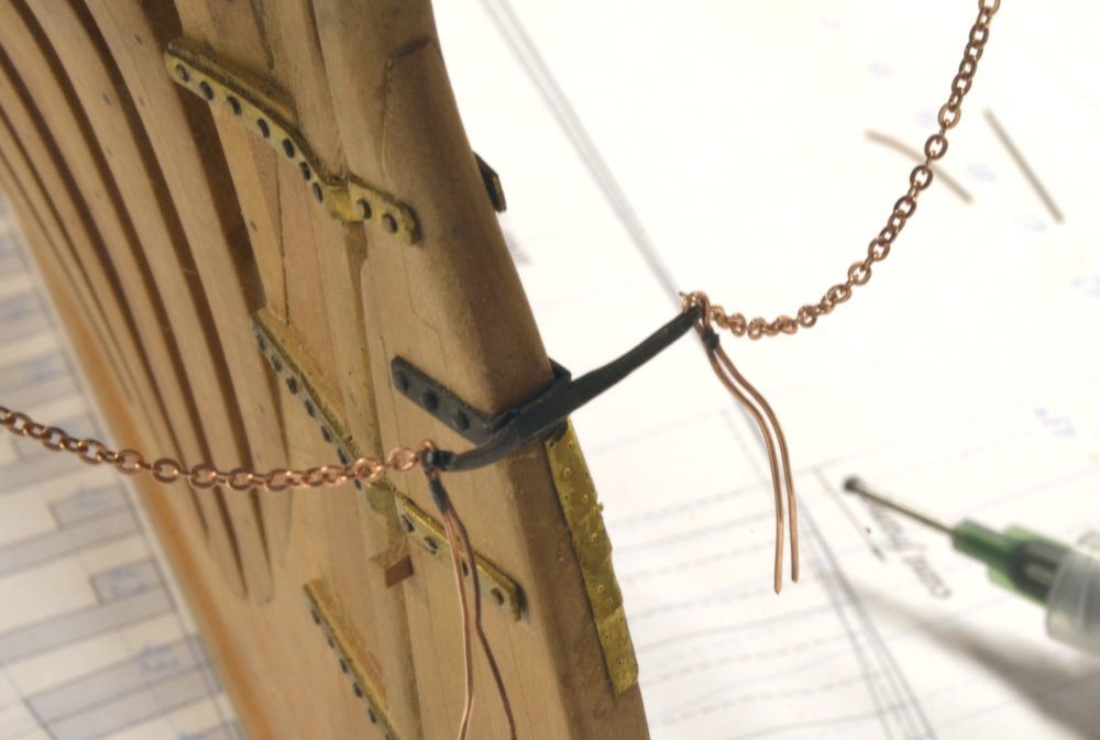
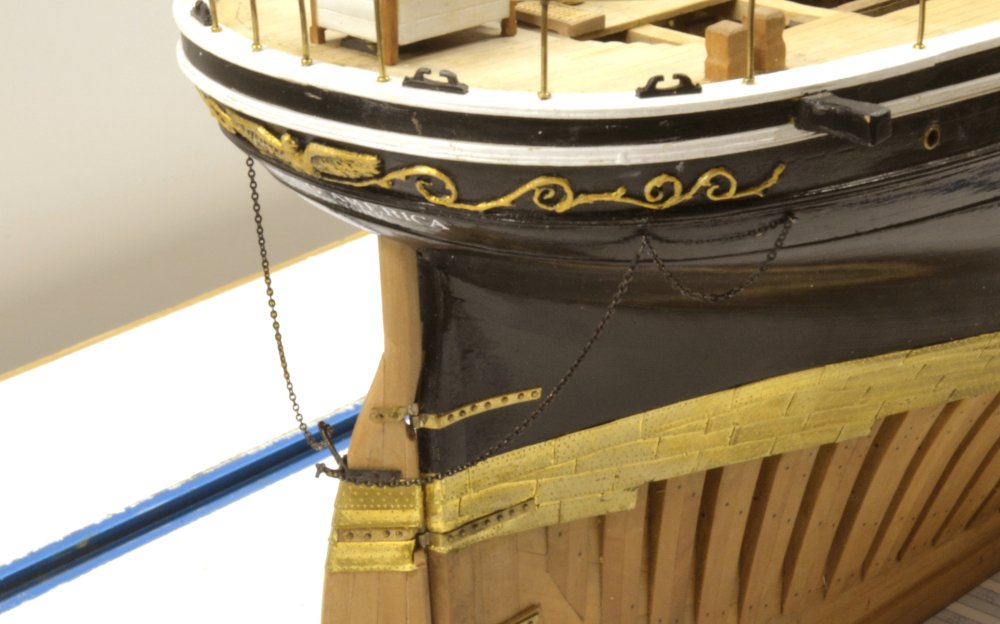
Young America - extreme clipper 1853 Part 169 – Rudder Pendants Another small item of work completed today – the rudder chain pendants. But first, I made a small modification to the binnacle to give it a larger base and to improve its overall proportions. The additional base was added as a brass bottom disk as shown in the first picture. The rudder pendants, sometimes called preventers, were provided to prevent loss of an unshipped rudder or as a means to operate the rudder from the deck in the rare event of a steering gear failure. They consisted of chains on either side of the stern, bolted to the hull. I used 30 link per inch copper chain for the rudder pendants. At 1:72 this equates to 30 links per fathom. After cutting the chains to length, eyebolts were fitted to the chain. I am making all eyebolts for the model by spinning copper wire. The wire is looped over a bent pin hook in a hand drill and the two ends held in a vise. The drill then spins up the shaft of the eyebolt. In this case the end link of the chain was first slipped over the wire. In the next picture the wire (and chain) has been spun and the shaft is being clipped off. The wire in this case was 26 gauge. Most eyebolts on the ship will be made from 22, 24, or 26 gauge wire. The eyebolt and chain are shown in the next picture. Each pendant is anchored to the hull just below the sheer rail at two points, so a second eyebolt was fitted part way along the chain by the same process. Some 26 gauge wire was then threaded at the other end to make a shackle to the rudder horns. This is shown in the next picture. The pendants were then hung from the stern as shown below. The next picture shows some copper-phosphorus solder applied to the shackles. Silver soldering these this way is a bit risky, but this is what happens when you do not plan ahead. It would have been much better to have done these shackle connections before the horns were mounted, but this will do. The torch flame was kept well away from the wood and at just enough gas to flux the solder on the thin wire shackles. The next picture shows the finished pendants after blackening with liver of sulfur solution. In the picture the rudder is turned hard to port to check that sufficient chain has been provided and rudder movement is not hindered. Ideally the chain stays above the load waterline at all rudder positions. Ed

- 3,618 replies
-
- 28
-
-
- young america
- clipper
- (and 1 more)
-
Thank you, Janet. Would you care to disclose whose drawings? I only know of one set, those by Bill Crothers, except of course my own that come with the book(s). I'd like to know if there are others. Thanks, Ed By the way, we just spent a week in Warwickshire.
- 3,618 replies
-
- 2
-
-
- young america
- clipper
- (and 1 more)
-
Thank you, Richard. Most appreciated. A source I had not seen before. Looks like a good selection of chain. Ed
- 3,618 replies
-
- 2
-
-
- young america
- clipper
- (and 1 more)
-
Thanks, everybody, for the comments and likes. I wish there were more progress these days, but as I said, things are a bit slow in the workshop this summer. Maury, I do not expect to be making chain link by link, but over the past months chain has been on my mind. There is a lot of it on the model. Apart from the obvious anchor chain, lower yard ties, rudder pendants, bobstays, bowsprit sharouds and the like, there is a lot of smaller chain in the rigging, mainly the halliards and sheets for the topsails and above. Some of this is quite small. The actual sizes range from 10 to 92 links per fathom. At 1:72 this converts nicely to 10 to 92 links per inch. I have located and obtained copper/brass chain as small as about 35 links per inch but will be needing a solution for the smaller sizes. Have some ideas and some test pieces to simulate the small sizes, but I would not call the problem solved yet. If someone knows a source for chain smaller than 40 links per inch, I'd be interested. Ed
- 3,618 replies
-
- 2
-
-
- young america
- clipper
- (and 1 more)
-
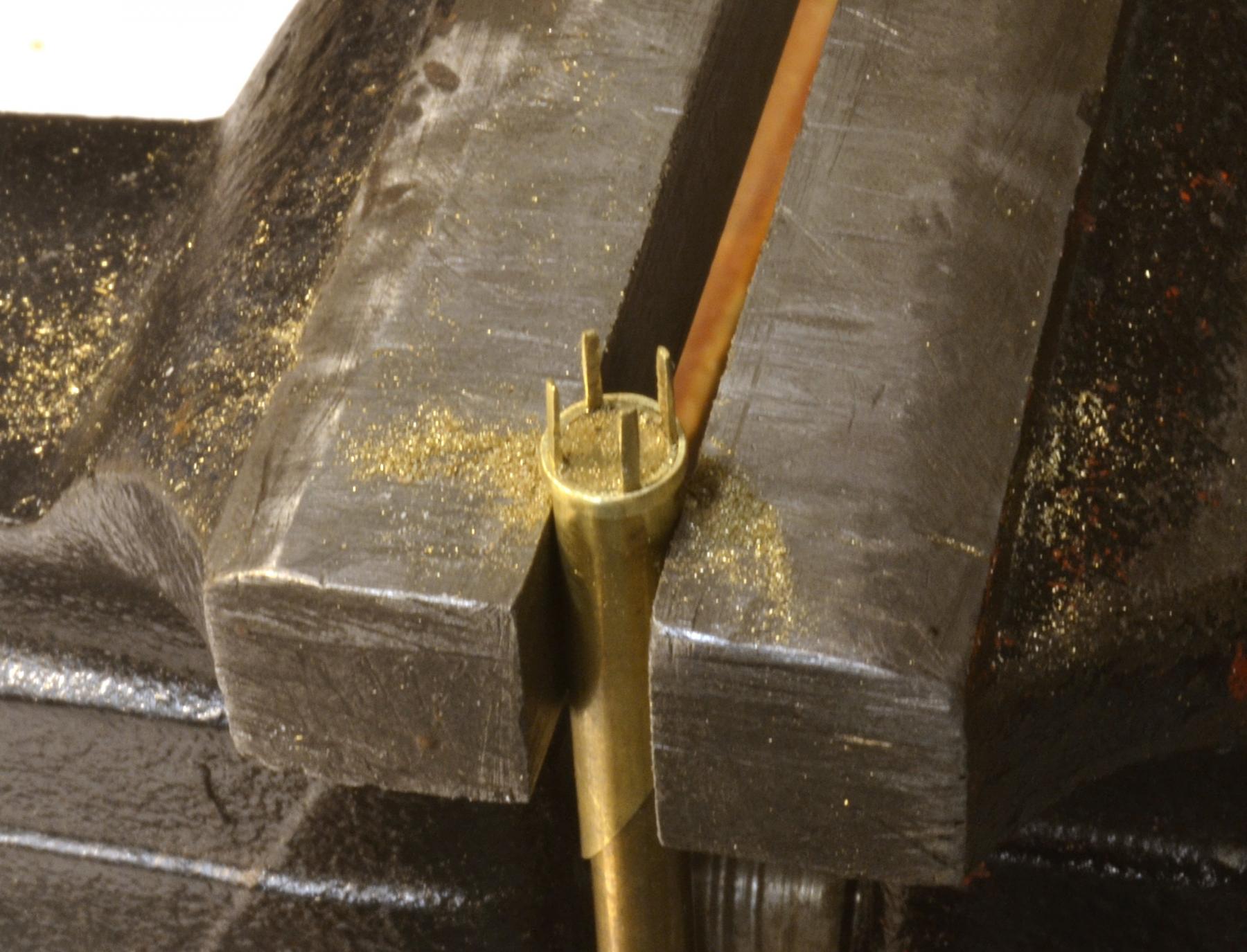
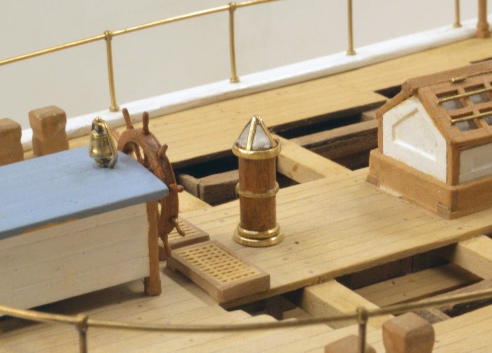
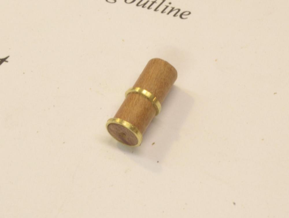
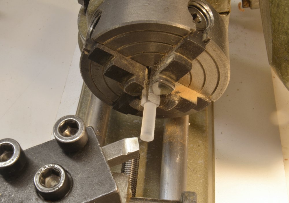
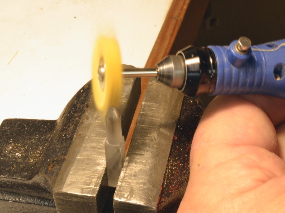
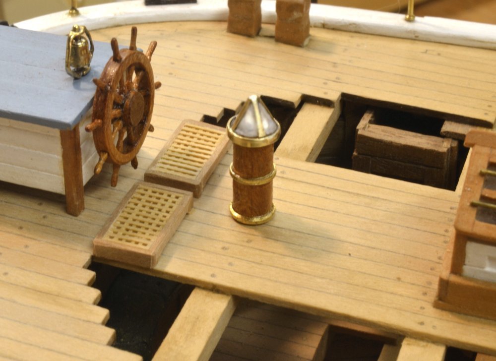
Young America - extreme clipper 1853 Part 168 – Binnacle "Odds and ends" seems to be the order of the day for the past month or so. Not the best prescription for a lazy, hot summer. Too easy to procrastinate. Big consuming tasks are better. On these little projects it is first research, then the drawing, then the modeling and photos – one step at a time. The binnacle is one such piece. A small part, but to judge by the mess left in the shop, one would think it had been the entireTitanic. It started out as a cherry cylinder, turned to the ID of a brass tube from which two decorative rings were turned. The next picture shows stage 1. The four-paned glazed top was next. It too, was made from a section of the same tube with the glass mullions filed out on the end as shown in the next picture. The solid rod in the tube helps establish a constant depth and prevents the vise from squashing it. The next larger size tube was used to make a ring to fit around the bottom of the top – shown below. Telescoping tube is very handy for making a variety of assemblies. I try to keep a stock on hand. The mullions were then bent to the center and the assembly silver soldered. The parts at this stage are shown below. The cap was then sawed off the tube. I did not want to leave the top without glass but making and fitting small panes like this is well beyond my ability, so I decided to make a small Plexiglas® prism to fit inside the brass top. In the next picture a rod is being turned to the diameter of the wood cylinder. A four sided prism was filed at the end of this until it fit well in the brass top. It was then polished using Micromesh® sticks, followed by buffing – shown below. The assembly was finally glued together using small droplets of thin CA. The final piece is shown positioned on deck in the next picture. I guess the two rudder pendant chains will be next. Ed


- 3,618 replies
-
- 42
-
-
- young america
- clipper
- (and 1 more)
-
The photos of the full ship are very impressive - as is the overall work. Very nice, Nils. Ed
- 2,625 replies
-
- 5
-
-
- kaiser wilhelm der grosse
- passenger steamer
- (and 1 more)
-
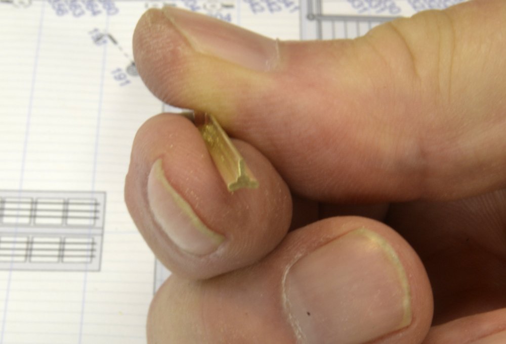
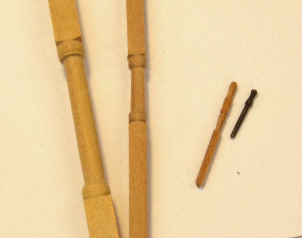
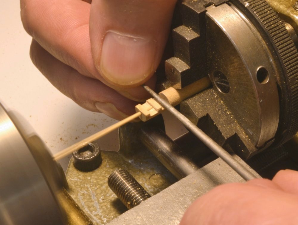
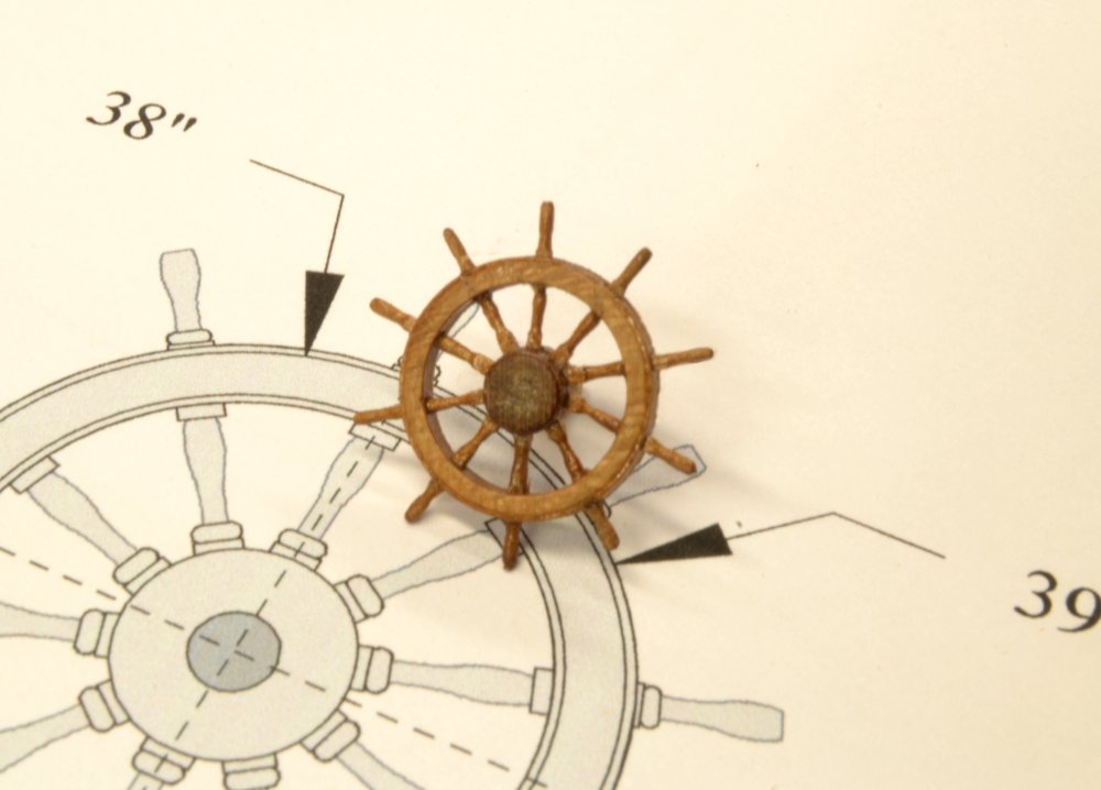
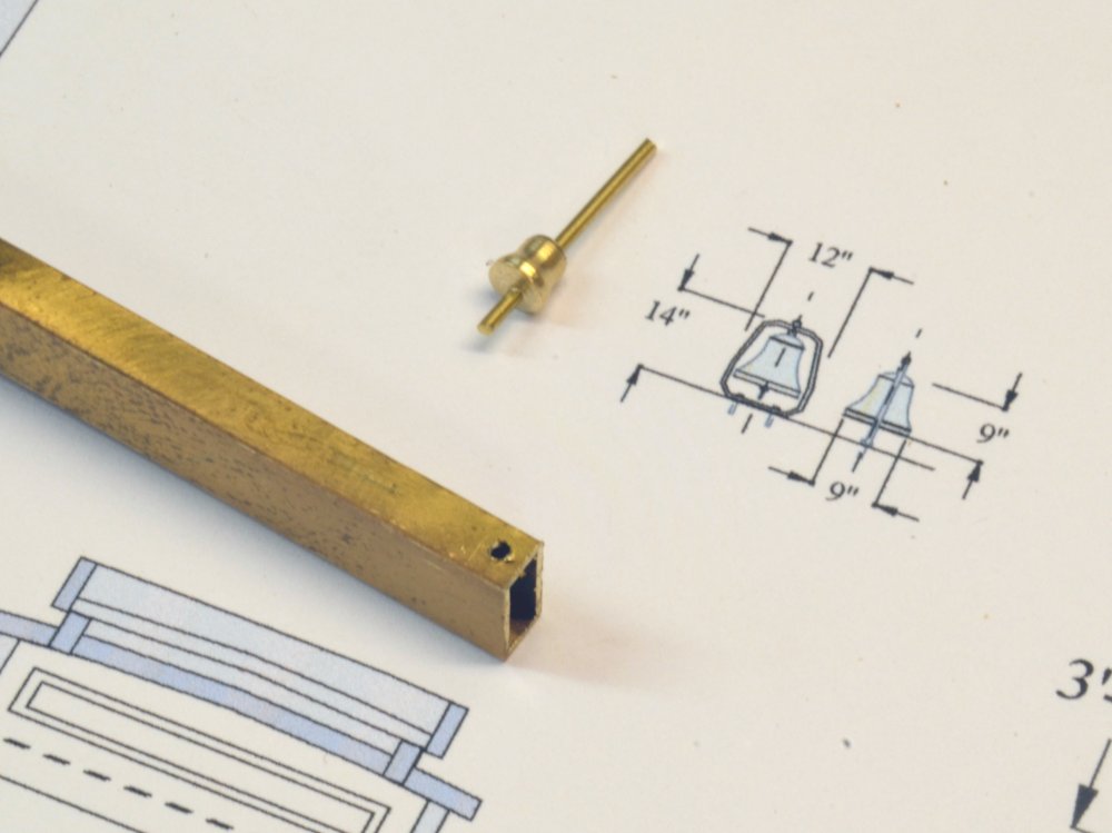
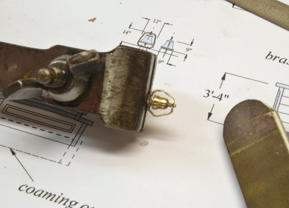
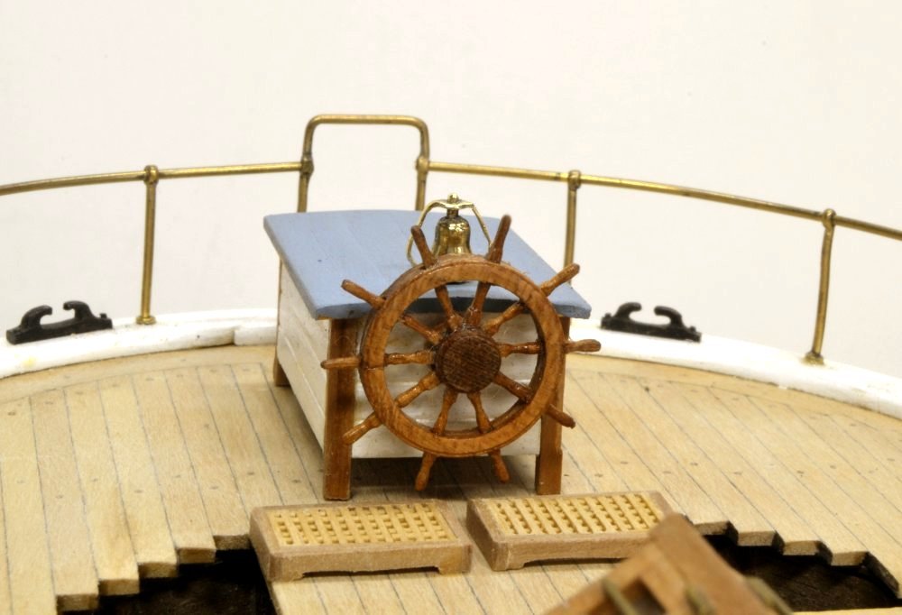
Young America - extreme clipper 1853 Part 167 – Helm Details So, it has been a month since the last post – seems longer. Not a lot of modeling being done this summer, mostly just odds and ends getting ready to start masts and rigging. This week I made a replacement for the first wheel and added the bell to the rudder head enclosure. First the wheel. I wanted to make two improvements to the first wheel. I wanted to add turned spokes to replace the simpler hand filed spokes on the first version shown in earlier posts. I also wanted to downsize the section on the rim to make it lighter and less clunky than the first. One of the turned spokes is shown in the first picture next to the belaying pin. The picture shows the four sizes of spindle turned pieces on the model. A different turning method was used for each. The largest is a turning of one of the 8" beam support pillars. The rounds on these were turned with a shaped tool. To its right is a 4" fife rail, turned with a single pointed tool. At the far right is a 2" belaying pin, turned from a round brass rod using a hardened steel filing guide. These are the smallest turnings so far. There are 300 of them on the ship. The methods used for these three turnings were described briefly in earlier posts. The wheel spokes were turned using a simple filing guide and fine files as shown in the next picture. Because the 2½" spokes are so small and fragile I made the first set of European Boxwood. The final set used in the wheel were turned from .032" cherry heartwood square strips. Making the hub/rim was described earlier. In the next picture the new wheel, with spokes installed, is being parted off in the lathe. The final cherry wheel is shown in the next picture. The bell is a simple brass turning drilled for the rod shown inserted below. The bracket for the bell started out as a rectangular brass section. In the next picture it is being shaped and polished. The last picture shows the new wheel and bell mounted on the rudder head enclosure. The wheel was finished with a small amount of polyurethane, instead of the wax finish I normally use. So far, none of the deck has been waxed because there are still many rigging attachments to be made. The enclosure itself is only temporarily fitted on pins and will be stored away until much later. Ed

- 3,618 replies
-
- 44
-
-
- young america
- clipper
- (and 1 more)
-
Looks great, Gary. I have to hand it to you and everyone else who has the stamina to cut out all the pieces ( and label them and keep them organized), then go on to assembly. Its all to much of one thing at a time for me. I cut out the parts for one frame, assemble it, erect the frame then go on to the next, hence no labels on the Naiad frame parts. My apologies. Ed
-
Addendum 4 to Volume I Attached are Forecastle Pattern pdfs that correct the carrick bitt patterns and add dimensional information for these. The purpose of this modification is to clarify windlass axle bore sizes for both 1:72 and 1:96 scales and to help ensure that the windlass drive gears clear both the deck and the underside of the forecastle breast beam. Also attached is pdf for frame Xa, corrected to add toptimber bolt holes. 1to72 Forecastle Patterns.pdf 1to96 Forecastle Patterns.pdf Xa.pdf
-
Very fine work, Frank. Very nice. Wonderful detail. Ed
- 649 replies
-
- 6
-
-
- dunbrody
- famine ship
- (and 2 more)
-
Thank you, all. Making those simple sheaves was a good way to get back to work - the real work - more belaying pins. David, the file is a Grobet, medium cut, barrette. Rob, I am lucky enough to have an autographed copy of the book and have almost memorized it, so I guess the answer is "yes." Ed
- 3,618 replies
-
- 7
-
-
- young america
- clipper
- (and 1 more)
-
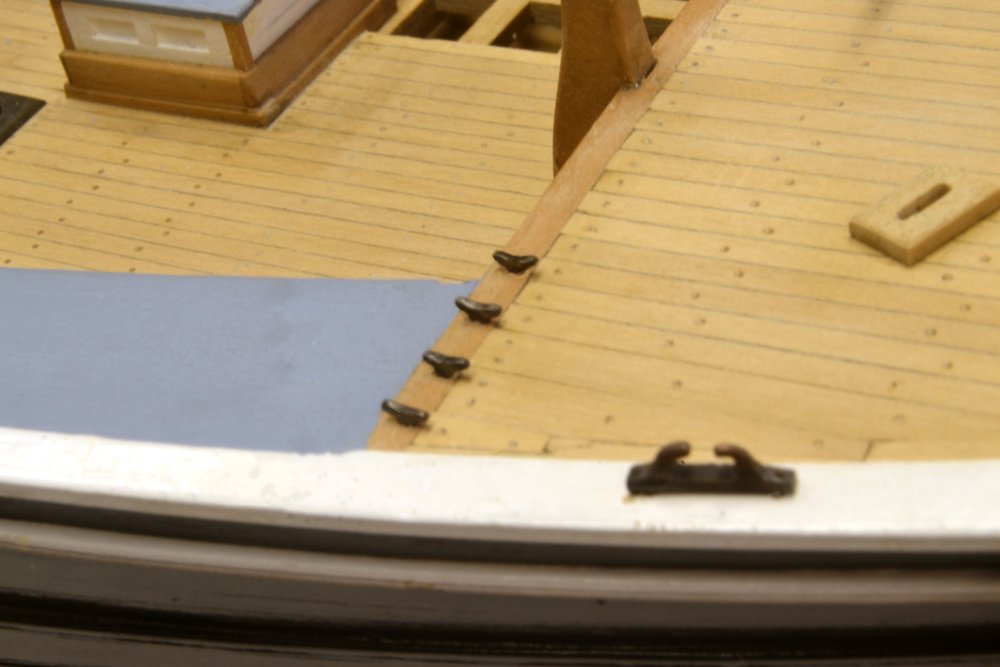
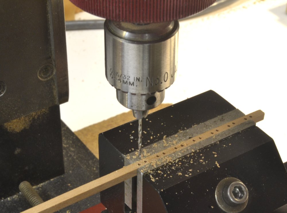
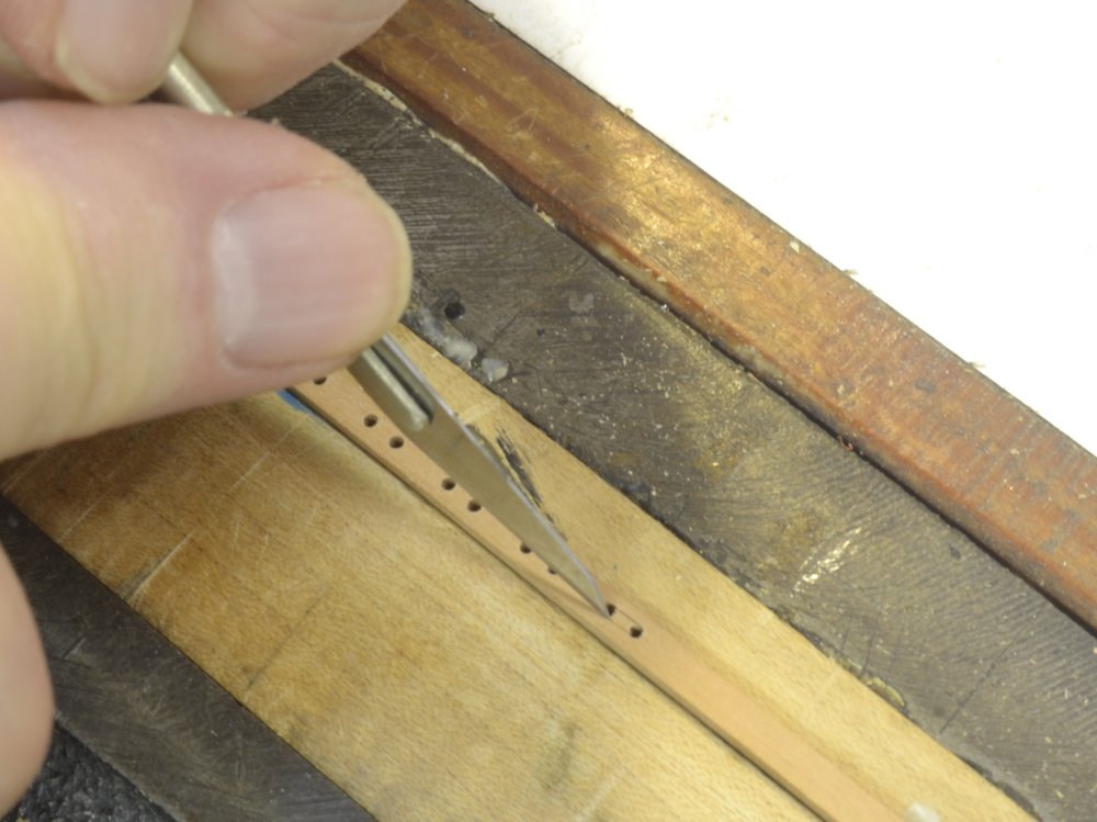
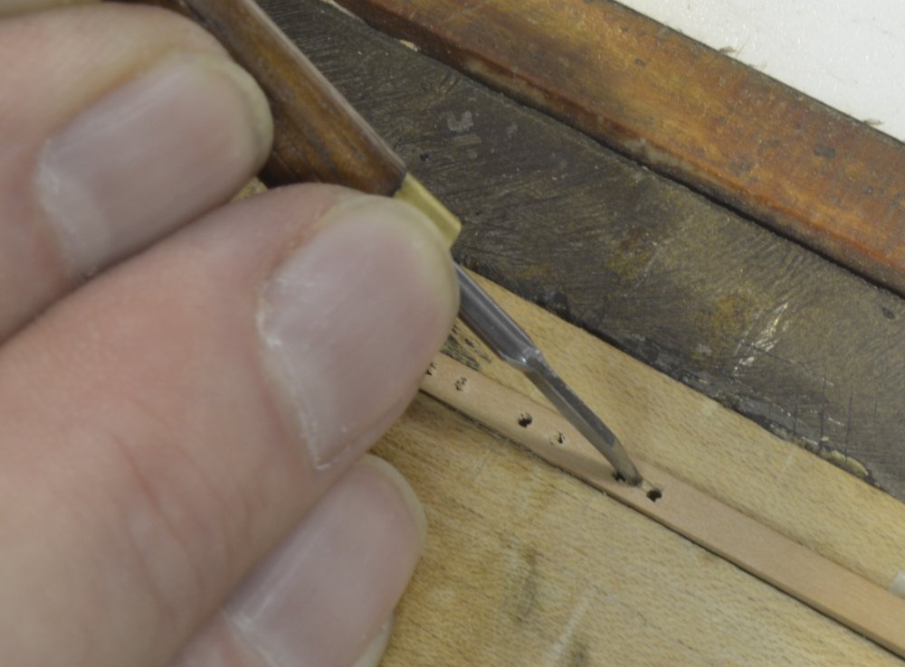
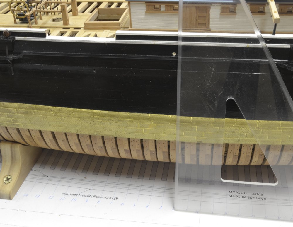
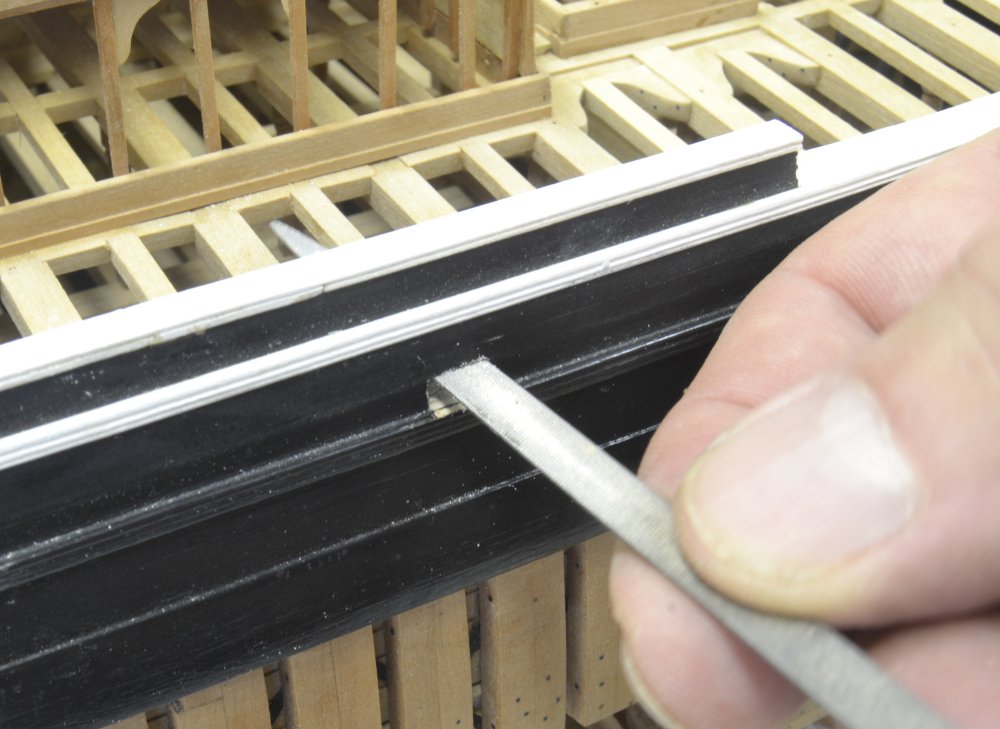
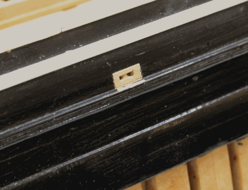
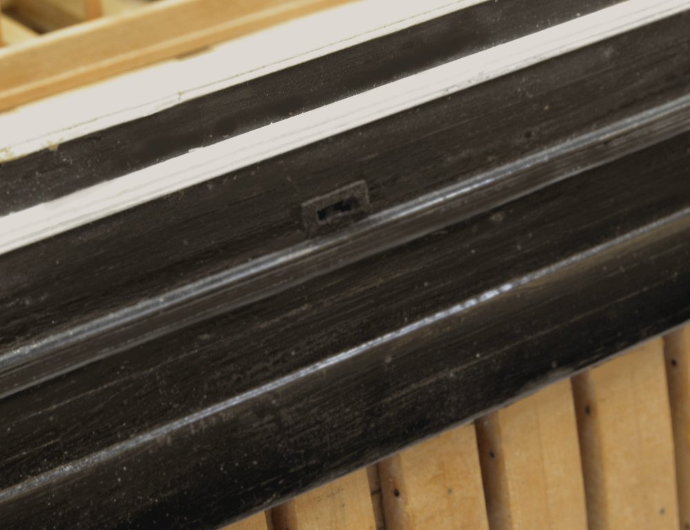
Young America - extreme clipper 1853 Part 166 – Bulwark Sheaves Well. I finally got some time in the workshop for a couple hours today for the first work on the model in over a month. Only a small task today – making and fitting the four bulwark sheaves that lead the fore and lower course sheets through the sides. I toyed with fitting sheaves in the frames for these but the assemblies are quite small and after rigging, the sheaves will be completely hidden by the lines. So I used the simple method of drilling holes, spaced at the sheave diameter into a strip of 8" x 8" stock as shown in the first picture. The sheaves were then carved into the strip. The first step was to outline the sides of the sheave with a sharp knife as shown below. A small chisel was then used to give the sheaves a round shape. The strips were then cut into the 20" long sheave assemblies that would be mounted in the bulwarks. In the next picture the position of one of the sheaves is being marked up from the base drawing station lines using a triangle.. One end of each of the assemblies butts against one of the top timbers with its lower face laid on the planksheer. In the picture one of two holes has been started within the outline of the sheave assembly. These were then drilled through the planking. The next picture shows a rectangular opening being filed out to fit the sheave assembly. In the next picture the assembly has been glued in flush with the outside of the planking. After installing, these were painted black on the outside and white on the inside to match surrounding woodwork. A small task, but one of a few that remain to get the model ready for masts and rigging. Ed
- 3,618 replies
-
- 29
-
-
- young america
- clipper
- (and 1 more)
-
Looking great, Nils. I have been catching up a bit. Dust is a problem, especially on those close up photos we love to take. Ed
- 2,625 replies
-
- 5
-
-
- kaiser wilhelm der grosse
- passenger steamer
- (and 1 more)
-
Looking terrific, Gary. Ed