HOLIDAY DONATION DRIVE - SUPPORT MSW - DO YOUR PART TO KEEP THIS GREAT FORUM GOING! (Only 27 donations so far out of 49,000 members - C'mon guys!)
×


EdT
-
Posts
2,214 -
Joined
-
Last visited
Content Type
Profiles
Forums
Gallery
Events
Everything posted by EdT
-
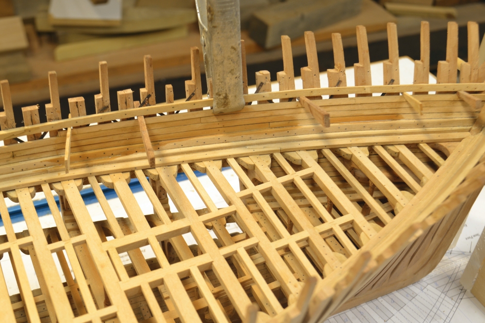
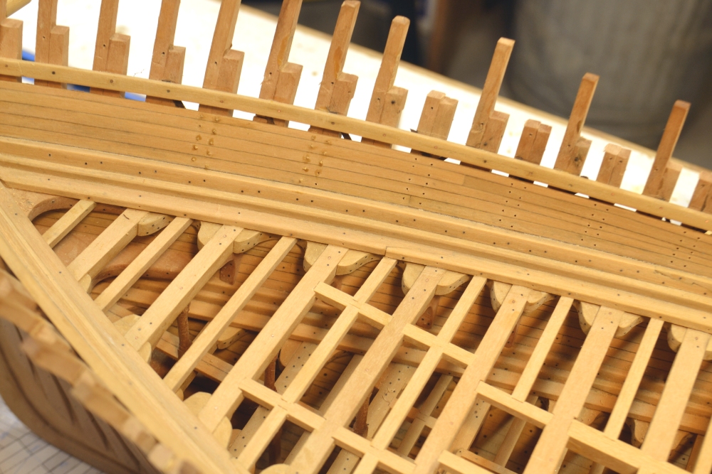
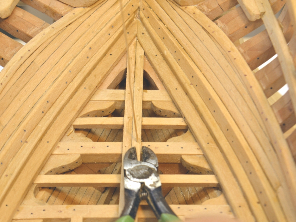
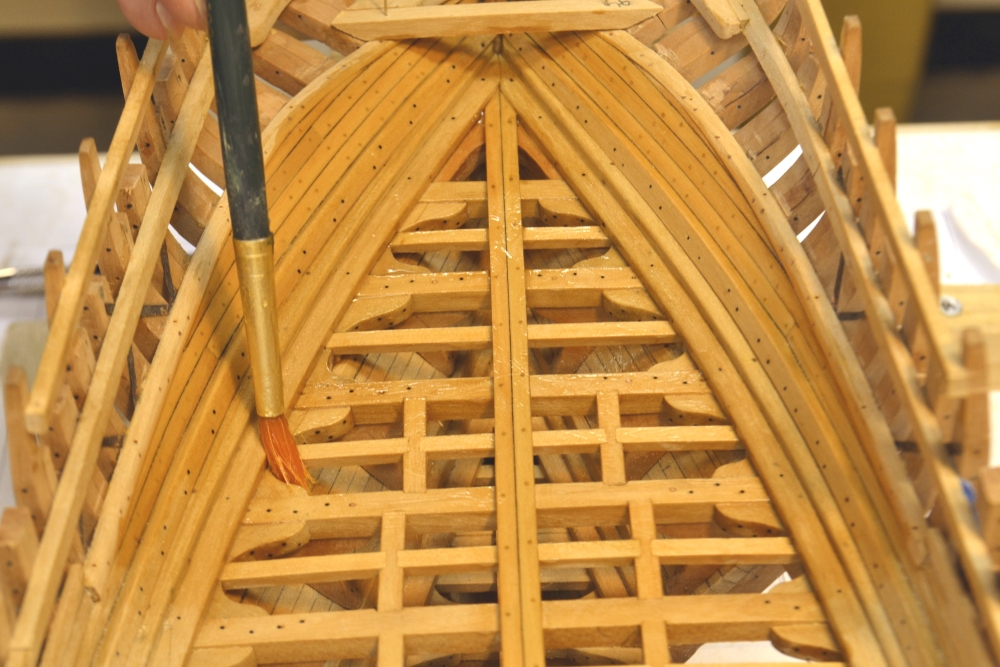
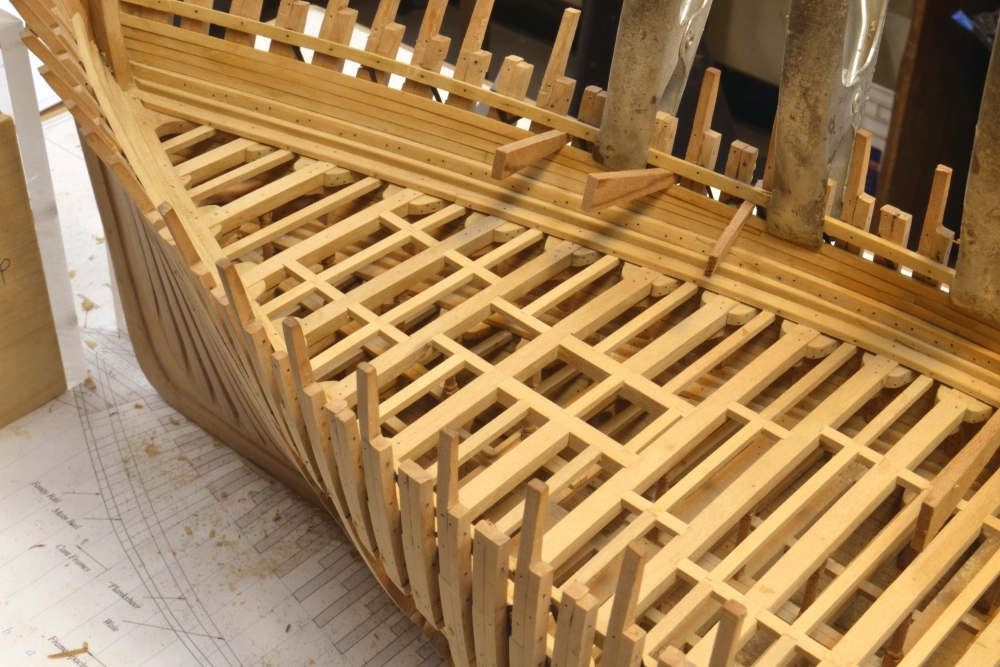
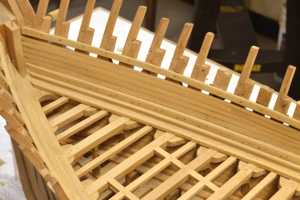
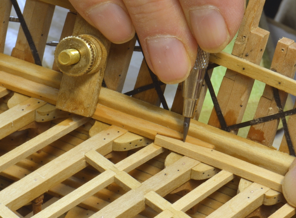
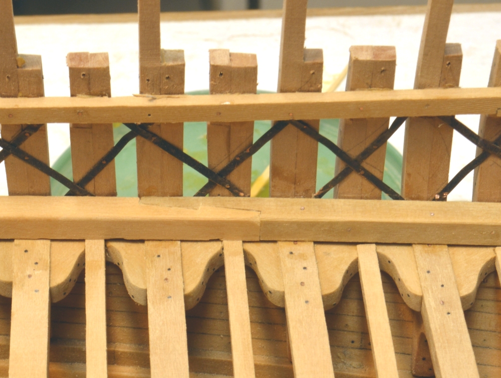
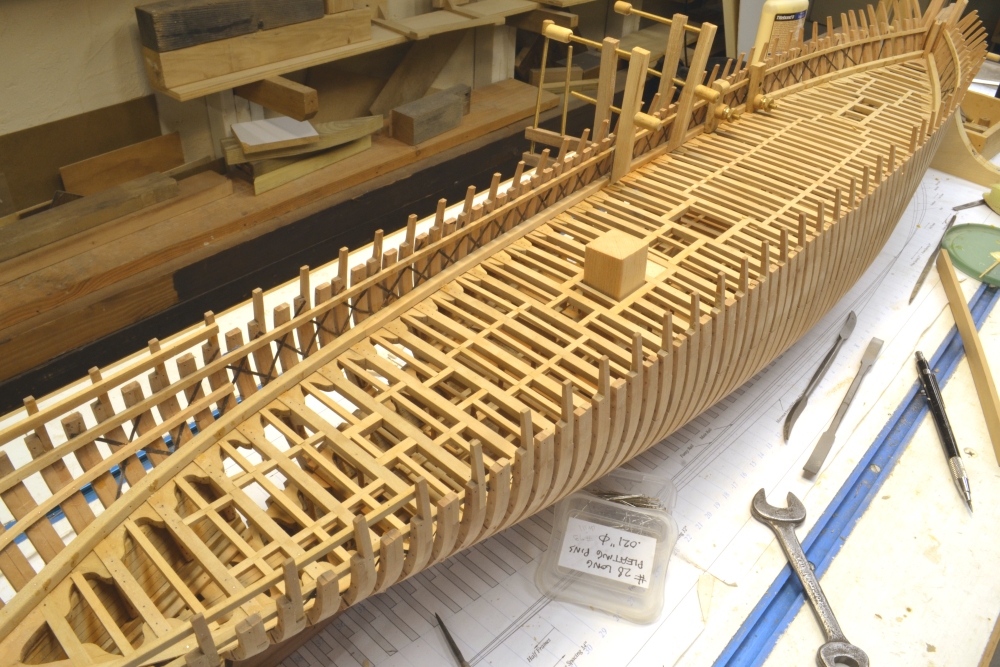
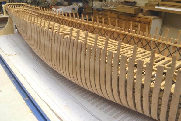
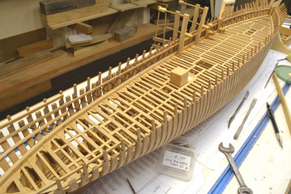
Young America - extreme clipper 1853 Part 87 – Middle Deck Inboard Planking continued In the first picture the last strake of inboard planking on the port side is being installed – leaving the air strake above it. Treenailing has begun on both sides. The next picture shows some nails installed and holes drilled for the next group. The treenails measure 1½” (.021”) in diameter and are drawn from long strips of Castelo. The next picture shows the completed forward area above the middle deck. The next picture shows a treenail strip being inserted into one of the aft deck beams – about to be clipped off. The aft part of the middle deck is the first to be finished off so the beams of the cabin deck can be installed next. The cabin deck is just a few feet above the middle deck. In the next picture the middle deck work in this area below the cabin deck is being given a coat of wax – below the clamps. In the next picture the wax has sunk in and dried. The aftermost cabin deck beam has been glued in. The next picture shows another view of this. The next step will be to fit the deck beams and their knees for the cabin deck framing. Treenailing along the rest of the deck continues. Ed


- 3,618 replies
-
- 27
-

-
- young america
- clipper
- (and 1 more)
-
Mayflower by SawdustDave - Finished
EdT replied to SawdustDave's topic in - Build logs for subjects built 1751 - 1800
Interesting process for making the tops, Dave. I assume tou cut the angled ends on the side pieces to get sufficient glue surface? Nice job. Those knees should really strengthen the assembly. Ed -
Micheal, If its a long lost relative, you might be a long lost heir to a ton of money. The company was successful and had a huge business for more than a century. They made everything from toilet fixtures to tanks to cast iron fencing starting in 1828, They eventually moved to Trenton, NJ. You can find their catalog on line. I guess a lot of us have a bit of model railroading somewhere in our past. I remember an article in the 1960's on using Strathmore paper to make all sorts of simulated iron structures, including trusses. It was sold by ply then - 2 ply, 3 ply, etc. and by surface - high, medium, etc. I haven't seen those designations for years - but I still have my ponce wheel. Ed
- 3,618 replies
-
- 4
-
-
- young america
- clipper
- (and 1 more)
-
E&T, I look forward to seeing your results. File folders are not what they used to be - probably now made from recycle. I probably should have used Bristol or something harder, but I believe the shellac soaking will protect it well - and as I said it is buried in the depths where it is difficult to see and out of harms way. I started using card many, many years ago on model railroad structures. Those that have survived in my basement still look good. Best of all, its easy to use. Ed
- 3,618 replies
-
- 1
-
-
- young america
- clipper
- (and 1 more)
-
HMS Naiad 1797 by albert - FINISHED - 1/48
EdT replied to albert's topic in - Build logs for subjects built 1751 - 1800
Beautiful work, Albert. Your workshop is almost as perfect as the model. Ed -
Thanks for the comments and likes. They do keep my nose to the grindstone. Work on the "tween decks" planking is going very fast. Maybe its the learning curve, but it does get easier at the top. Revier, Ihave not seen you on the forum for awhile. Ed
- 3,618 replies
-
- 2
-
-
- young america
- clipper
- (and 1 more)
-
I agree with Druxey that this does not look like the inside of frame for the reason he cites. After looking at the drawing again, I sggest that this line is the joint between he stem and the apron that backs the stem. It appears to be parallel to the forward face of he stem over its length. I suggest measuring the distance between the dashed line and the forward line of the stem and check it against the scantling for the molded breadth of the stem (I believe 18"). You could also check the distance from the ashed line back the the solid line against the scantling for the apron (I beleive 11"). It would make sense to show this line dashed as a reference since the length on the gun deck - a primary measure - would be from the aft side of the stem - not the apron - to the sternpost. Ed
-
Top notch work as always, Danny. Ed
-
Mark, The dashed line and its intersection with the decks makes no sense to me. I can offer no suggestion apart from poor draftsmanship. This is an inboard works drawing and not a disposition of frame, which might be more accurate on this detail. I suggest you look at the half breadth plan and plot the intersections of longitudinal lines on the stem to determine the location of the rabbet. this may offer a clue to the lines in the elevation drawing. Ed
-
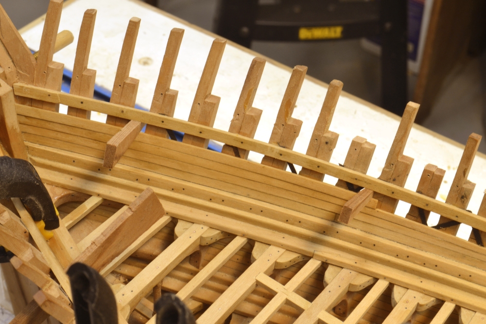
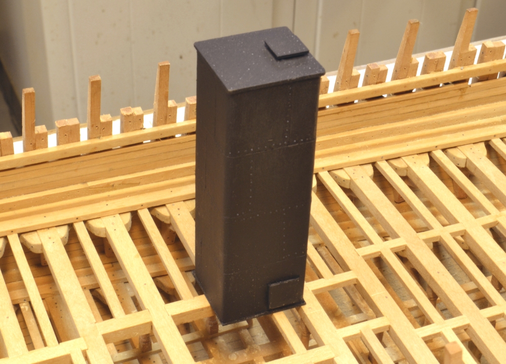
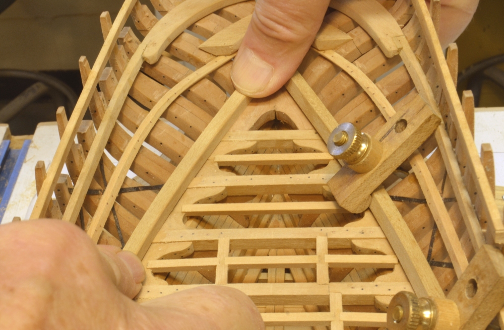
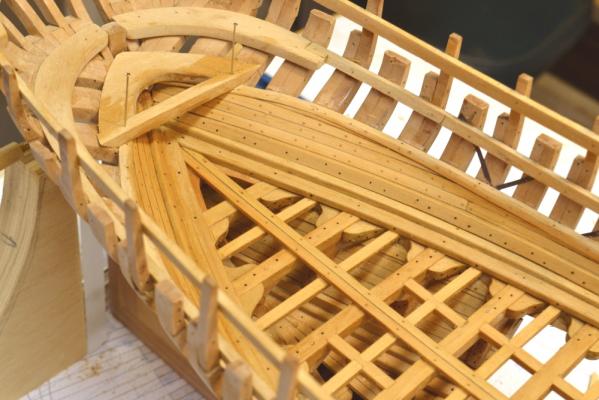
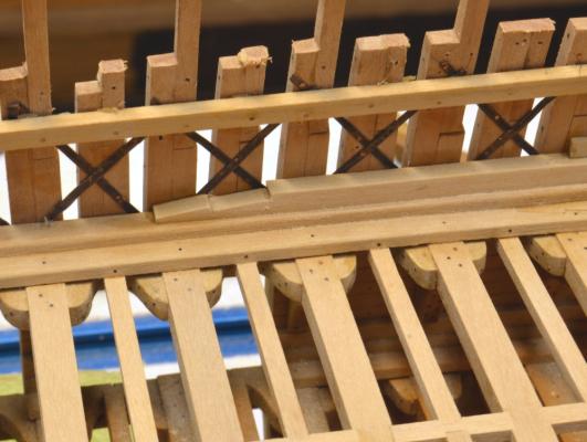
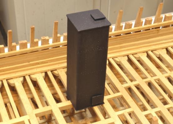
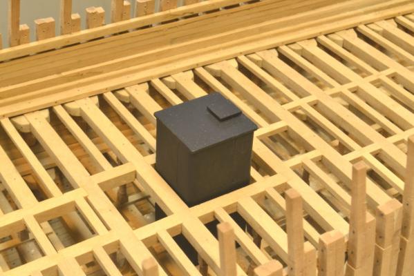
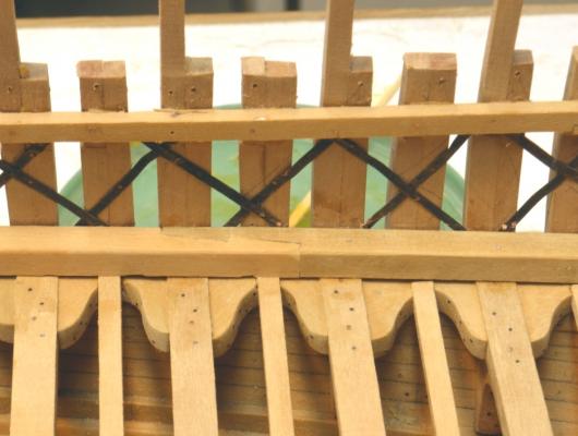
Young America - extreme clipper 1853 Part 86 – Middle Deck Inboard Planking Heavy members – standing strakes – 10” thick by 12” deep are fitted over the waterways and bolted through every frame timber to further reinforce the connection of the deck structure to the frames. These members are joined along their length by hook scarphs as shown in the first photo. These members were also bolted down into the waterways but I omitted these bolts because they will be covered by the next higher planks. In the next picture some of those planks are being installed and holes are being drilled for the standing strake bolts. Note that the top strake being installed is notched for a drop plank to account for the widening planking band where the hull flares out at the bow. The next picture shows a higher strake being glued in – wedged down to close the joint. Standing strake bolts have been installed in this picture. In the next picture, the next section of that plank is being glued – wedged and clamped in this case. I did not bother to jog the planking joints in this work, because hanging knees will hide this detail. Long planking strips were used and their joints placed under a knee location. The next picture shows the completed planking – except for treenails – at the starboard bow. The gap above the top plank is an “air strake” – left open to ventilate the space between frames above the keel. The next picture shows the larger of the two fresh water tanks ready to be rigged into the opening in the decks. In the next picture the tank is placed temporarily in position. The top of this tank will be just below the main deck planking. A smaller tank located just forward of this one has yet to be fabricated. I did not go overboard in making these tanks. They will be difficult to see at best. I used the wood blocks shown earlier, some file folder and a ponce wheel for the rivets. After assembly the paper was impregnated with dilute shellac and finished with flat black enamel. The detail of the actual tanks, like many other things, is a bit of a mystery. Webb’s Challenge had rectangular iron tanks so I followed that design. I based the design for these on pictures from the JL Mott catalog from 1886. Mott was the foremost New York ironmonger from 1828, making a large range of iron goods well into the 20th Century – a likely source for these tanks. The catalog featured cast and wrought iron sectional tanks. It is likely that these large tanks would have been of the wrought iron type – probably lead lined. They were built up to the required size in formed modules. The top and bottom manways are speculative. No nozzles yet. Ed


- 3,618 replies
-
- 33
-
-
- young america
- clipper
- (and 1 more)
-
Thanks, everyone. Druxey, Lauchlan McKay - less famous brother of Donald - estimated quantities of iron bolts at 68 lbs per measurement ton amd copper bolts at 8 lbs per ton. Given those estimates and Young America's 1,961 registered tonnage, there would have been about 70 tons of iron bolts and 8 tons of copper bolts used in her construction. I am actually surprised that these figures are not larger. It would be interesting to compare these ratios with 18C Royal Navy ships - if anyone has data. I have not looked. Ed
- 3,618 replies
-
- 3
-
-
- young america
- clipper
- (and 1 more)
-
ROYAL CAROLINE 1749 by Doris - 1:40 - CARD
EdT replied to DORIS's topic in - Build logs for subjects built 1501 - 1750
Lovely collection, Doris. You have much t be proud of. Beautiful work. Ed- 883 replies
-
- 1
-
-
- royal caroline
- ship of the line
- (and 1 more)
-
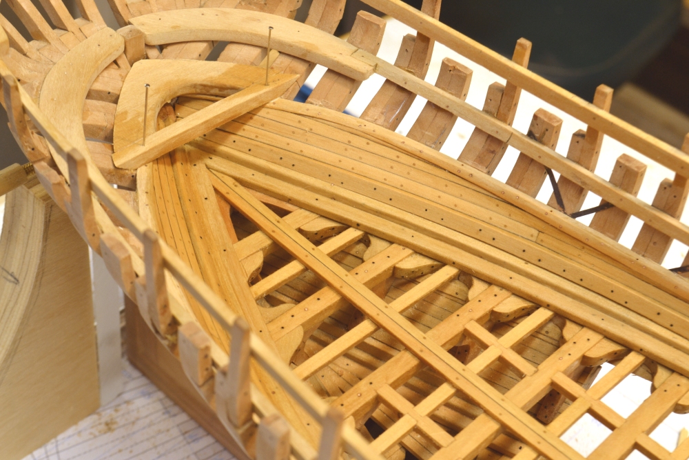
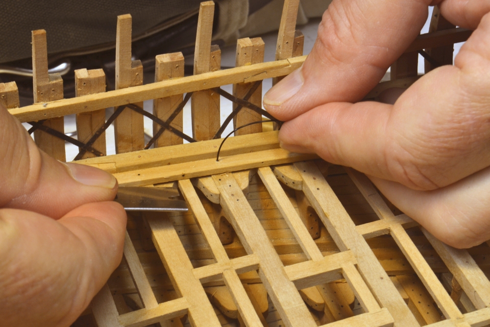
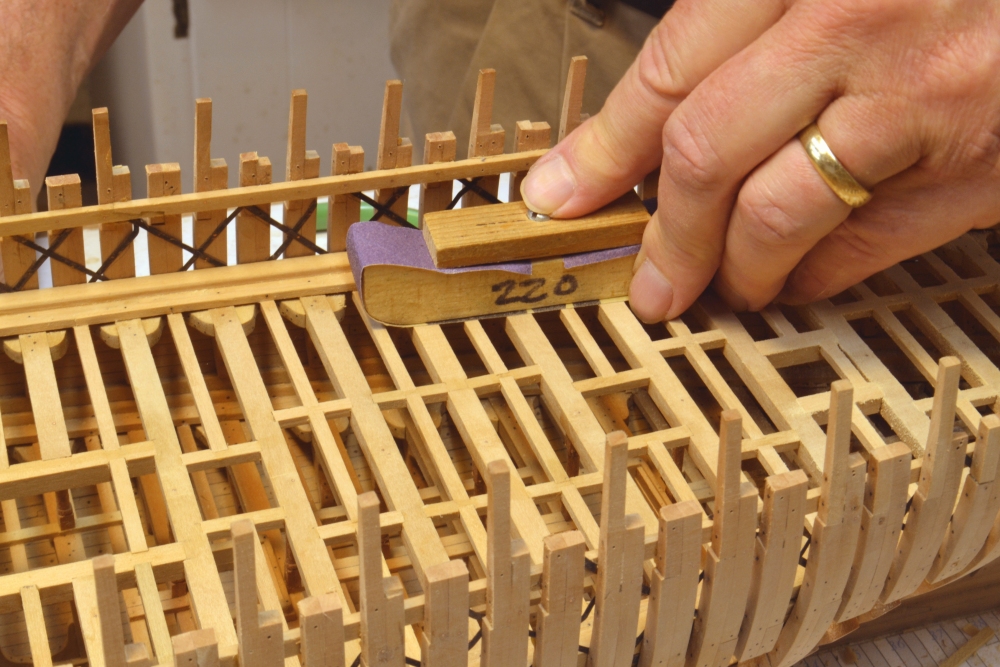
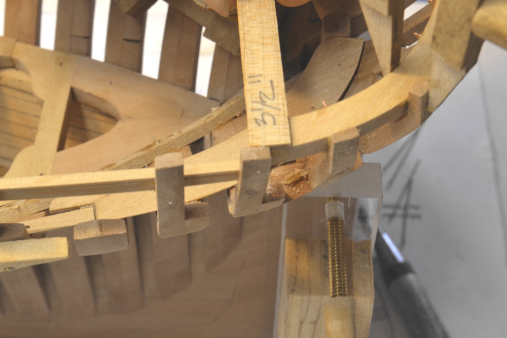
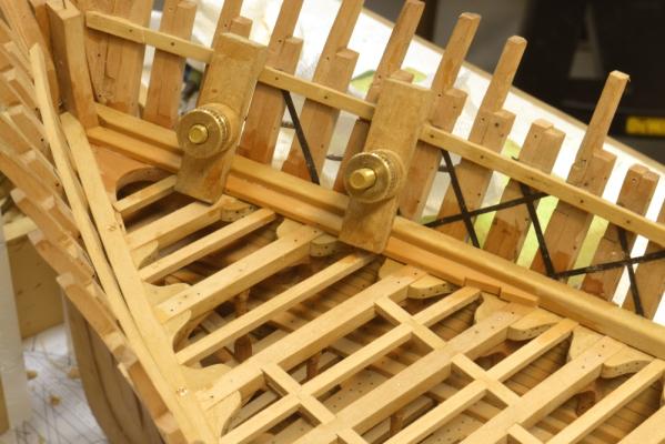
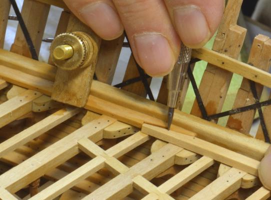
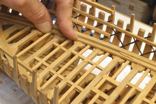
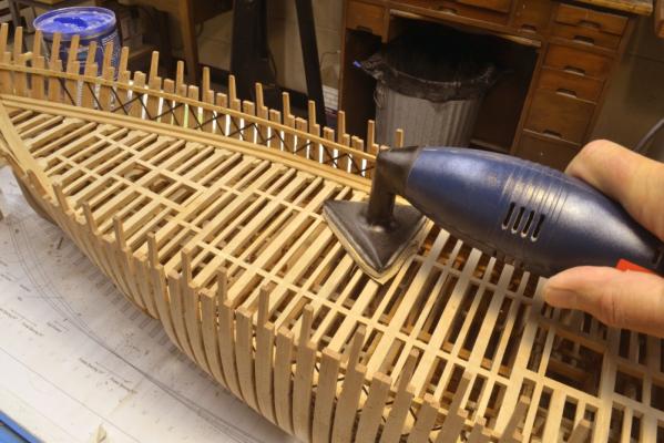
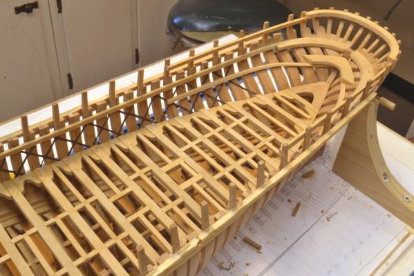
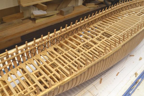
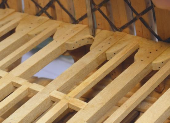
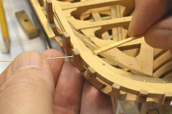
Young America - extreme clipper 1853 Part 85 – Middle Deck Binding Strakes The binding strakes provided an additional reinforcement to the connection of the deck beams to the hull frames. These 8” thick members, placed against the inboard face of the waterways, were bolted vertically into each beam and horizontally – edge bolted – through the waterway and each frame. On the model I represented this bolting with monofilament – one down through each beam and one edge bolt above each ledge between beams. There were probably twice this many bolts used on the real ship. The first picture shows the forward section of binding strake on the starboard side being glued in place. The binding strakes were joined with hook scarphs as shown in the photo. They were also rounded over or beveled down to the deck planking on the inboard side. In the next picture the joint measurements are being transferred to the end of the next section. The length of the hook is being marked here, The piece was cut back to the angle first. The next picture shows the last section on the port side at the stern being fitted. The next picture shows the binding strakes installed at the bow – ready for bolts. The holes for the horizontal bolts were drilled before installation – those for the vertical beam bolts after. In the next picture a length of monofilament is being glued in to represent one of the beam bolts. After installation of the binding strakes the deck was given a final leveling with 220-grit paper as shown below. This was followed by final sanding using 220 then 320-grit paper – by hand and using the detail sander shown in the last photo. Next will be installation of the side inboard planking, starting with the heavy 10” x 12” standing strakes over the waterways. Hatch coamings and some decking can also be started. Ed


- 3,618 replies
-
- 30
-
-
- young america
- clipper
- (and 1 more)
-
Thank you all for these generous comments. I am away this week but hope to be back in the shop and have a new posting soon. Cheers, Ed
-
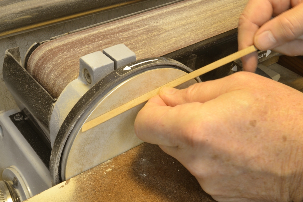
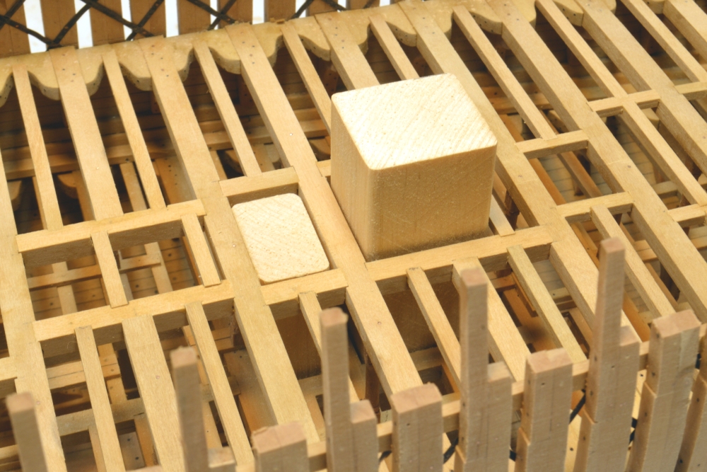
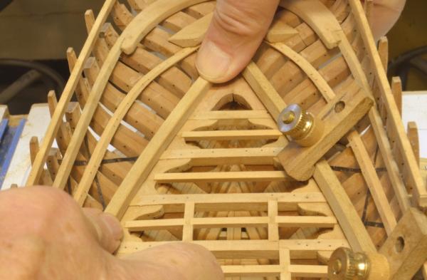
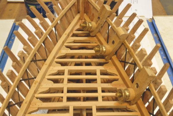
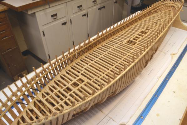
Young America - extreme clipper 1853 Part 84 – Middle Deck Waterways The first picture shows the hull with the temporary ribbands removed and the toptimbers and upper futtocks cut down to final height. The outsides of the upper hull have been given a light sanding. The hull will be planked on this side down to slightly below the load water line. With the middle deck framing complete, the next step was to install the waterways. In the next picture the curved sections at the stern have been boiled and are clamped in place to dry overnight. The same was done at the bow. These are rough-cut waterways, unbeveled at this stage. After drying they were cleaned up with sandpaper and beveled to lie flat against the angled aft frames. Most of this was done on the disk sander as shown below, then trimmed by hand. In the next picture the aft starboard section is being fit. The unfinished port member is still in the clamps. In the next picture the forward starboard section of waterway is being glued in. The waterways are pretty massive – 15” x 15”. They are bolted into each beam and through each frame with iron bolts. On the model these are 22-gauge copper wire glued in with epoxy as discussed earlier. The sections are joined by hook scarphs as shown in the next picture. This area has not yet been bolted. The next picture shows the last section of waterway being glued in. This picture also shows wood blocks cut to the size of the two fresh water tanks and set on their bases in the hold. The next picture is a closer view of these. These blocks will probably be the fabrication bases for modeling these two iron tanks. The larger of the two comes up to just under the main deck. Next, the binding strakes inside of the waterways. Ed


- 3,618 replies
-
- 25
-
-
- young america
- clipper
- (and 1 more)
-
Interesting comments on field fitting. Drawing accuracy has its limits. There are two considerations (at least): While I have utmost confidence in the precision of my drawings and patterns for many things - for example hull profile, frame patterns, overall dimensions, longitudinal line heights and breadths, deck heights, locations of masts and other objects - some drawing representations are not as reliable. For example, the lines of the insides of the frames along a deck. While the outboard breadths of these can be well defined by taking breadths at deck side height from the body plan, the inboard breadths would require an accurate horizontal dimension through each frame. Molded breadhs through these frames vary with height and their horizontal breadths depend on the angle of the frame at the deck. These lines could be drawn by taking horizontal breadths from each frame pattern where the inside lines (and the bevel) are represented accurately, but that is an enormous task and the value of the result will be negated by the second consideration described below. These lines are useful for showing the overall layout and approximate shape of the decks, for example, but I always label them and other similar lines "for reference only." That says "field fit." Apart from the above, the primary problem in relying on drawings for every piece is accumulated construction error. Even with the utmost care, from the time the keel is laid, minute error begins to creep in and add up at every step of construction. By the time one reaches the first deck, small dimensional deviations should come as no surprise. Short of perfection, this error accumulation is inevitable so eliminating it is not a solution. It needs to be recognized. Field fitting becomes mandatory at some point in construction. That point can be determined by dimensional checking, but common sense is probably a better guide to when a field fit is needed. All the errors described above are small, but large enough to cause a gap in a joint or a sprung (or loose) beam. I do not even bother to loft some parts for these reasons - for example deck and breast hooks. Field fitting of these is easier and more accurate. So, again we find ourselves adopting the early shipyard practices - where drawings were few. Ed
- 3,618 replies
-
- 13
-
-
- young america
- clipper
- (and 1 more)
-
Great work, as always, Mark. Ed
-
Thank you all for the comments and questions. I like questions. Yes, Micheal, she is pretty solid. I think she may be ready for the Horn. That's part of my concern for the fairness of those toptimbers - there's not a lot of play in them once the decks are added. I have one more opportunity to pull/push any bad actors into line with the main deck beams. I may even have to replace one or two. We'll see. A very good question, Druxey, and the answer is: I don't know. Your suggestion is certainly a good way to do it and no less accurate for sure. I do like the feel of the gauge sliding over the tops as opposed to a pencil line. Perhaps that's it. Allan, except for frame assembly, I field fit just about everything - definately carlings and ledges. I do cut the carling scores from measurements out from the centerline before the beams are installed, but there is always some variation when fitting pieces between installed parts. I space the ledges between beams by eye. The pencil mark shown in the post is only a guide for the first cut. Even when cutting from thin pencil lines, I have to remember - inside the line? on it? or outside? - probably because of my unsteady pencil hand. Ed
- 3,618 replies
-
- 1
-
-
- young america
- clipper
- (and 1 more)
-
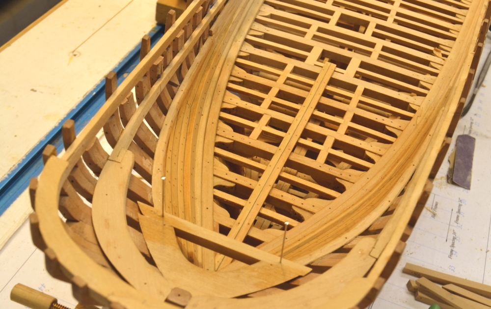
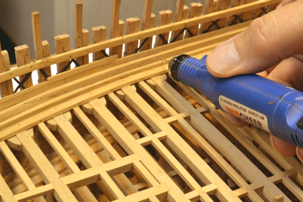
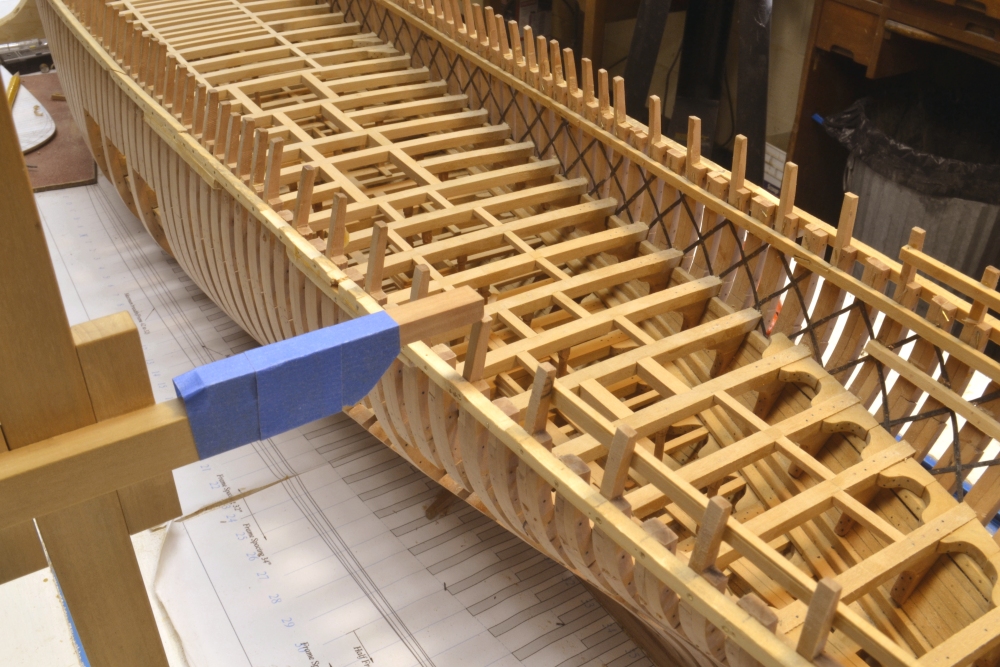
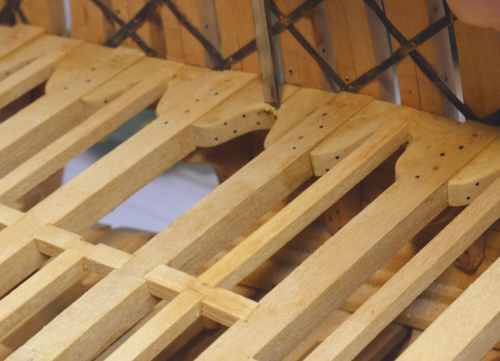
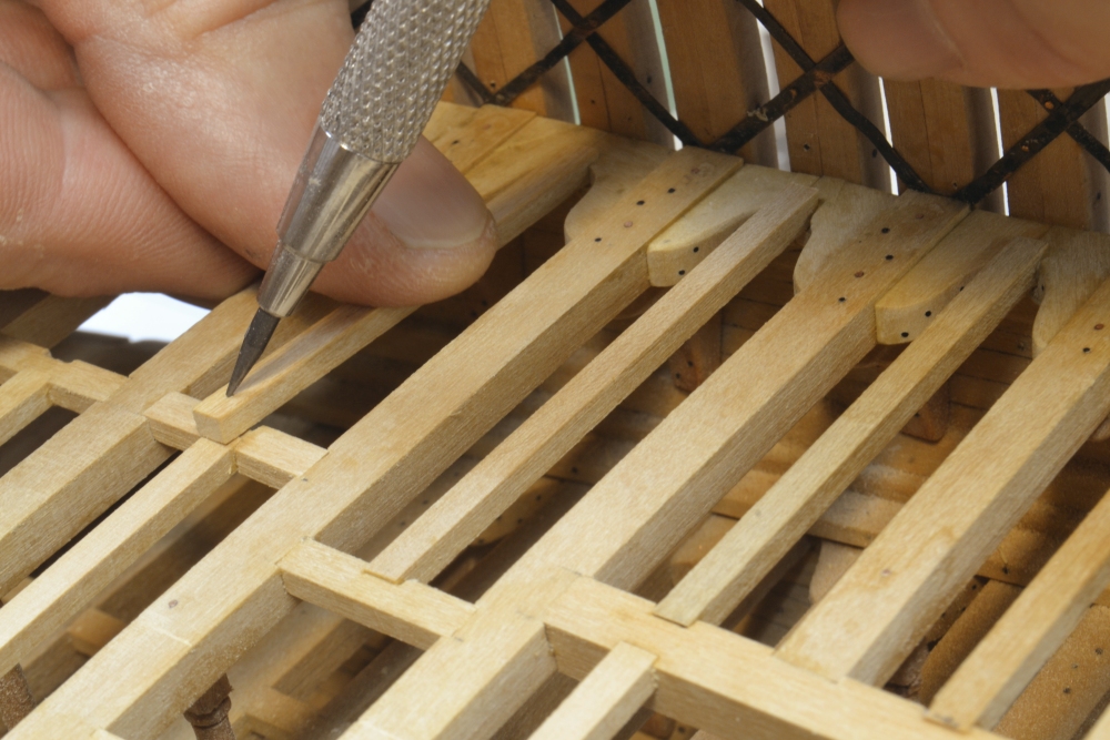
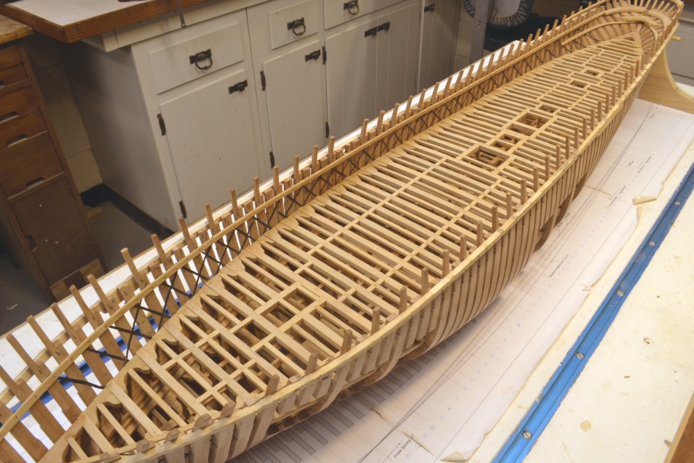
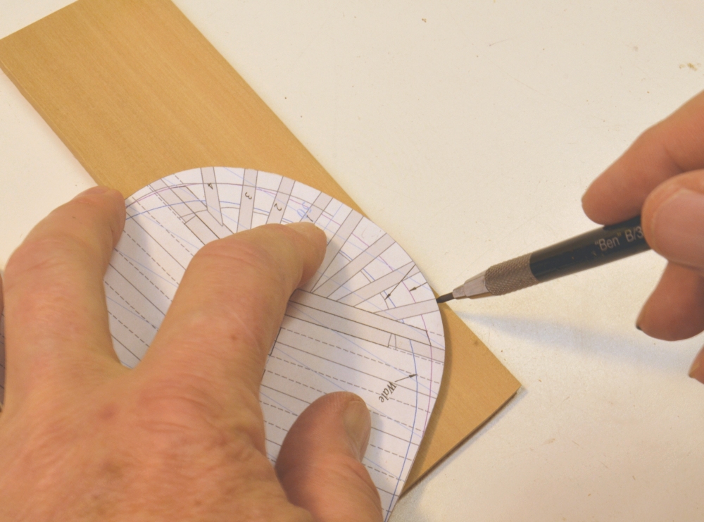
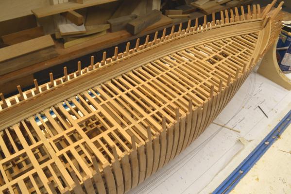
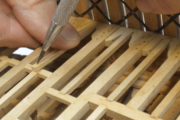
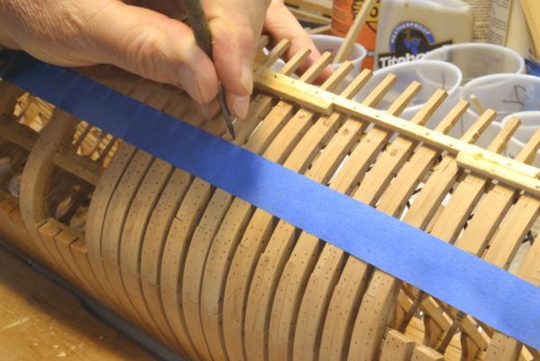
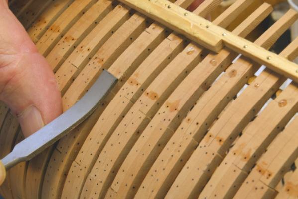
Young America - extreme clipper 1853 Part 83 – Toptimbers/Middle Deck Framing It has been almost two weeks since the last post. In that time, work was done to prepare the toptimbers for final alignment and the framing of the middle deck was completed. After aligning the toptimbers around the curved stern, all of the rest and upper futtocks – except those at the forecastle – were cut off and adjusted to their final heights. Toptimbers on the odd numbered frame lines were cut back to the planksheer line. The first picture shows the way the height gauge was used to set the tops of the timbers. A strip of wood was taped to the top of the gauge arm. The heights of the fancy rail and the planksheer were then set from the drawing for each frame and the heights on the model adjusted to match with a flat file. Each timber was filed horizontally until the gauge arm just slid over the top. The picture shows some of the toptimbers cut off. The tops of the frames are now ready for final fairing and installation of rails and outer planking. The clamps for the cabin deck were dubbed off and the stern hook for that deck made and installed as shown in the next picture. This short “mezzanine” deck is the next to be framed after completion of the decking and inboard planking above the middle deck. The next picture was taken during framing of the middle deck – specifically the installation of lodging knees and ledges. Some of the port side lodging knees have yet to be installed. The picture shows all of the toptimber work completed. The next pictures show some steps in setting ledges. In this picture a score for the ledge is being cut into the lodging knees at the side with a small chisel. The scores in the carlings were cut earlier with a triangular file. In the next picture a ledge has been fit into the lodging knee score and is being measured for its final fit. The last picture shows the completed framing of the middle deck. It will now be sanded fair. Work on the middle deck waterways will be next. Ed

- 3,618 replies
-
- 39
-
-
- young america
- clipper
- (and 1 more)
-
Thanks, everyone. To answer your question, Druxey, the hull will be rock solid with the beams and knees installed - as it is now up to the middle deck - even with those large cut outs for the view openings. The misalignment was prettry minor - two toptimbers less than 1/32" (actual) off line - but enough to be visible. There wil be more of these small adjustments needed along the toptimbers of the main deck, I am sure. This is a very long hull with no breaks in the top rail that runs from stem to stern. The planking at this level is quite thin (.035") and will not be stiff enough to help with alignment. Also, there is no inboard planking along the main deck, so the toptimbers must be quit fair on their own. The fancy rail (top rail) will help but because of painting, that will go on last, so I want the sides faired before that step. For all these reasons I am being extra cautious early on. I was not sure the clamping and wetting would do it, but with the template handy it was worth a try. It worked better than expected, so I included it in the post. It did not take much to fair the side. There was virtually no springback, This could have waited for the beams but it was better done sooner. Alan, fortunately the large clamp did not have to be very tight - not even enough to support its own weight - because it was able to rest on the temporary outboard ribband. The independent clamp jaws were also set to be parallel to the sides. Ed
- 3,618 replies
-
- 7
-
-
- young america
- clipper
- (and 1 more)
-
Outstanding research. A great example for all of us. Ed
- 346 replies
-
- 2
-
-
- terror
- polar exploration
- (and 2 more)
-
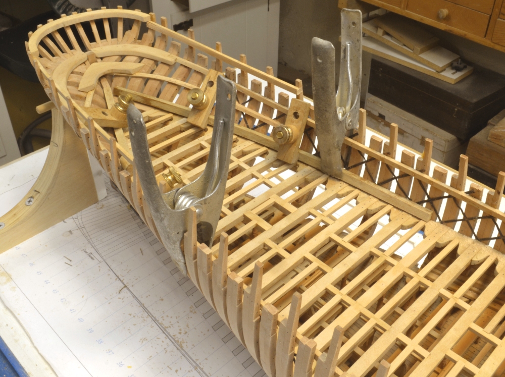
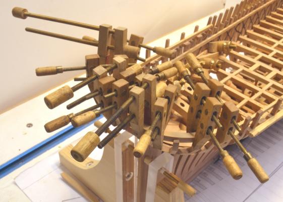
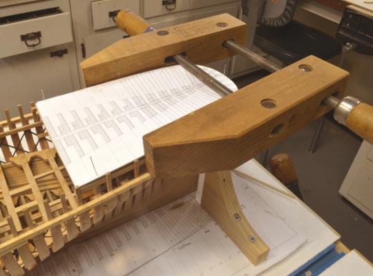
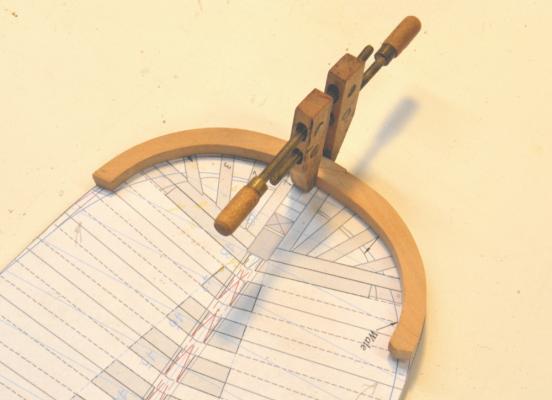
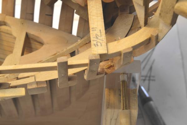
Young America - extreme clipper 1853 Part 82 – Stern Framing/Alignment At the end of the last part, I promised to complete the description of adjusting the stern into its precise shape. I have found that regardless of the care taken in aligning frames during erection there is always some degree of error that needs to be corrected at some later point – especially on something that will be as prominent as Young America’s beautifully curved stern. The heights of the stern timbers and the aft part of the poop deck were carefully set in the last part. This allowed the poop deck transom to be installed as shown below. There is a clamp on each of the glued stern timbers and aft cant frames to secure this piece – except in the case of two of the stern timbers that were about 3” outside the line. One can be seen in the above picture. After the glue on these had set, each of the glued timbers was through bolted with epoxied copper wire as shown in the next picture. As discussed previously, these “functional” bolts are glued at both ends. The two misaligned stern timbers were then clamped and glued as shown below. I wasn’t sure if these could be pulled into place or would have to be removed and reset, but fortunately they could be clamped and glued without distorting the other timbers. This picture also shows the concurrent installation of the cabin deck clamps, but this will be discussed later. With the circular stern lined up, there was a bit of work to do on the poop deck top timbers. There was a bulge of about 2” in the starboard side – enough to disrupt the symmetry of the poop deck when viewed from aft. In the next picture this is being remedied. The deck template has been pinned in place at three points. The slight bulge is being pressed into the template with the rather large Jorgensen clamp. The errant timbers were then soaked with water inside and out down to the middle deck clamps and left overnight. I anticipated further wetting and using a hair dryer on this are but that was not necessary. The timbers remained in their correct alignment when the clamp was removed as shown below. The alignment is almost perfect but it will be again checked and if necessary corrected when the cabin and poop deck beams are installed. The last picture shows this area with the template removed. With the frames in this area set accurately by their inboard faces, the outboard faces were sanded fair back to the specified 6” siding. The large pine ribbands on the outside of the hull are now redundant in this area at least and will soon be removed. This picture also shows the cabin deck clamps installed. I will get back to that later. Ed

- 3,618 replies
-
- 30
-
-
- young america
- clipper
- (and 1 more)
-
Thank you both. Dave, Longridge was a great teacher and his Victory a great inspiration. Alan, the tool is a flat Grobet #2(?)silversmith's riffler - a curved flat file that I use quite a lot. Athough my wife takes excellent pictures,I have not asked her to help with the model photos. A tripod, another fixture and the timer on the camera allow me to do this myself as the work proceeds. I got in he habit of taking a lot of in-process pictures for the Naiad books - about 300 per month - and the habit has persisted. Although I posted only two on making the transom, I believe I took 8 or 10. Ed
- 3,618 replies
-
- 5
-
-
- young america
- clipper
- (and 1 more)
-
HMS Victory by EdT - FINISHED - 1:96 - POB
EdT replied to EdT's topic in - Build logs for subjects built 1751 - 1800
Thank you, both. This model was special to me. It seemed to run through half my life in small spaced out episodes. Ed -
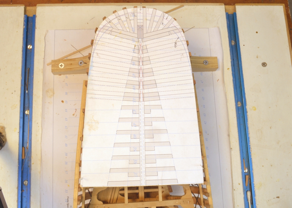
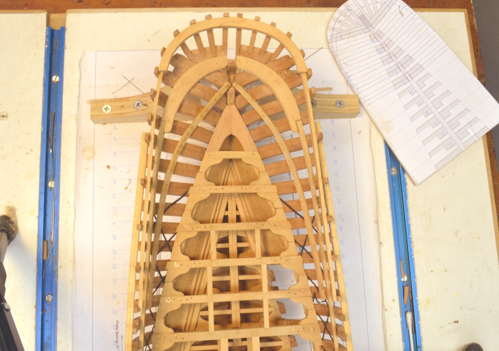
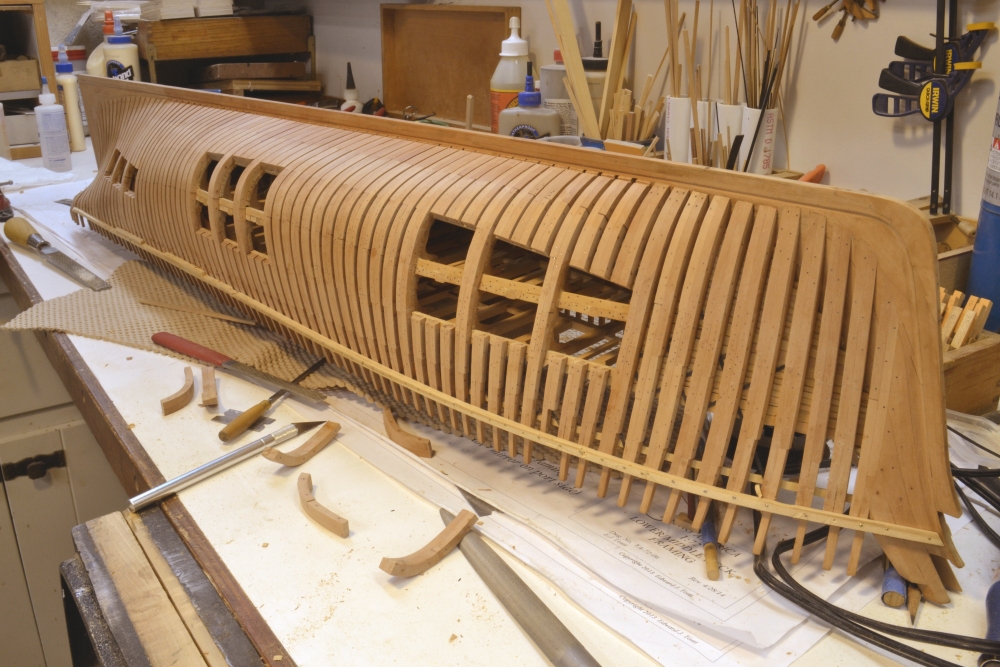
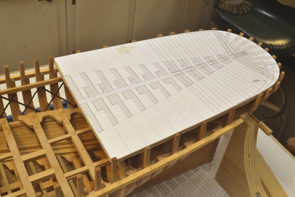
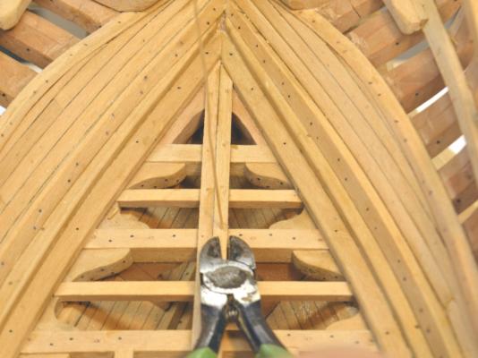
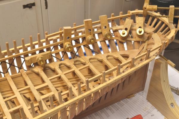
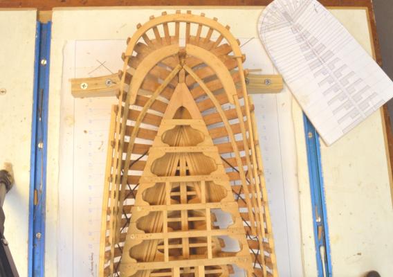
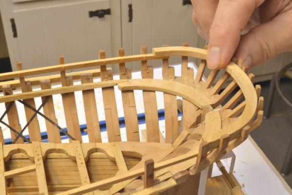
Young America - extreme clipper 1853 Part 81 –Aft Decks Framing To break the monotony of making more knees, I deferred the work to finish the middle deck lodging knees and went on to some other things that will be coming up on the agenda shortly. The first was cutting and finishing the view openings in the lower port side hull. he first picture shows the three openings cut out. The forward and center openings extend from the first futtock heads up the middle deck clamp – the aft opening only up from the lower deck. After these were cleaned up by filing, sanding, etc. – and while the model was inverted on the bench – all of the remaining simulated bolts were installed up to the level of the middle deck. The next picture shows hole locations being marked for the middle deck lodging knee bolts. The blue masking tape, set at the top of the deck clamp, is used as a guide for the lodging knee bolts. There is only space for three bolts through the frames for each knee bolt – one through the frames where there is a beam and two through each intermediate frame. The resulting 4-2-4-2 pattern can be seen in the next picture. The regular pattern is often disturbed by bolts for the iron strapping lattice. There is nothing regular about these bolt patterns. In this picture the next row of bolts – the middle deck waterway bolts – have been installed just above the lodging knee bolts described above. The remains of the CA glue on that upper row is being filed off in the picture. This picture also shows the vertical rows of hanging knee bolts through the even numbered frame pairs. All this work was done on both sides, but on the starboard side up to the waterline only. The starboard topsides will be planked so there is no need for simulated bolts. Work also started on the framing of the after decks. The main or upper deck extends only back to frame 36. From there aft it was a few steps down to a cabin deck located as a sort of mezzanine between the middle and main decks. At this point also, there were a few steps up to the poop deck. A template cut to the shape of the poop deck inside the frames is shown in the next picture. This template is for final checks on frame alignment. Also in this picture the toptimbers of the odd numbered frames have been removed in this area. These were helpful in aligning the frames but only extended to full height on the even numbered frames. The others will be cut down later. The template was also used to shape a curved deck transom for the poop deck as shown in the next picture. To avoid grain weakness issues, this was made in two pieces joined by a hook scarph. It is being glued together in the next picture. In the next picture the poop deck clamps have been installed and the transom is being fitted at the stern. The top of the poop decking will be flush with the tops of the frames. The frames will then be capped with the “fancy rail.” This rail runs in a line from stem to stern. In the next picture the tops of the stern timbers and frames have been precisely trimmed to their correct height and a gauge strip is being used to set the height of the transom from the tops of these timbers. There is some tolerance for error on the heights of the lower decks, but there is none here. Any variation will disturb the line of the upper rail and will be very apparent. The deck clamps also need to be precisely set. The one in this picture had to be shimmed up about 1” so the deck planks will be flush with the tops of the frames. My adventures with these very visible final alignments will continue in the next part. Ed


- 3,618 replies
-
- 26
-
-
- young america
- clipper
- (and 1 more)