HOLIDAY DONATION DRIVE - SUPPORT MSW - DO YOUR PART TO KEEP THIS GREAT FORUM GOING! (Only 24 donations so far out of 49,000 members - C'mon guys!)
×


EdT
-
Posts
2,214 -
Joined
-
Last visited
Content Type
Profiles
Forums
Gallery
Events
Everything posted by EdT
-
Thank you all very much for the comments and "likes". Yes, Druxey, the anniversary is approaching The time passes quickly. Then I look at the 80 MSW posts - and of course, the scrap bin. Dave, I am glad you liked the post. As far as skill is concerned, I would refer you to Allan's comment - the answer is usually in the process(es). Like Frank, in his comment, there is always trial and error before a good process evolves. I would add that in devising a process one should consciously think about specific outcomes desired and also process steps that are within reach. I can assure you that a good process magnifies skills. Sorry, its a favorite topic for me. See Naiad Vol1. Mark, you are quite right. Naiad's knees were pre-installed on the beams. They were different - and easier - because they were bolted to the sides of the beams. Only the face against the inboard planking need to be trimmed to fit - and it was easy to hold it to the side of the beam for fitting. The top of the knee could be trimmed off to match the beam - before or after attachment. On Young America, the knees - or standards per Allan - bolt to the underside of the beam, so both surfaces need to be fitted. I did pre-install a few, but as you say, they still had to be fitted with the beam in place. In the end, this was easier to do with the beam securely glued. The last few do become a bit of a headache, however, with the neighboring beams installed. Allan, special thanks for your comment. I got into the habit of taking step-by-step pictures for the Naiad books - 250 to 300 a month - so the processes could be covered in detail in the books. It has become a habit and doesn't add too much to the effort. The tripod does get in the way at times - in fact I knocked it over last month - but that is another story. There were actually about 20 pictures taken for the knee sequence. So, I left some steps out. I probably covered some of the steps earlier. You have it right. If you break it all down into doable steps - and keep Remco's advice in mind - its not that hard. This isn't the Sistine Chapel ceiling - well not usually. Thanks again, everyone. Ed
- 3,618 replies
-
- 7
-

-
- young america
- clipper
- (and 1 more)
-
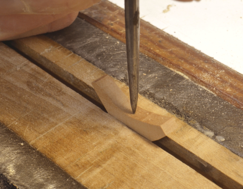
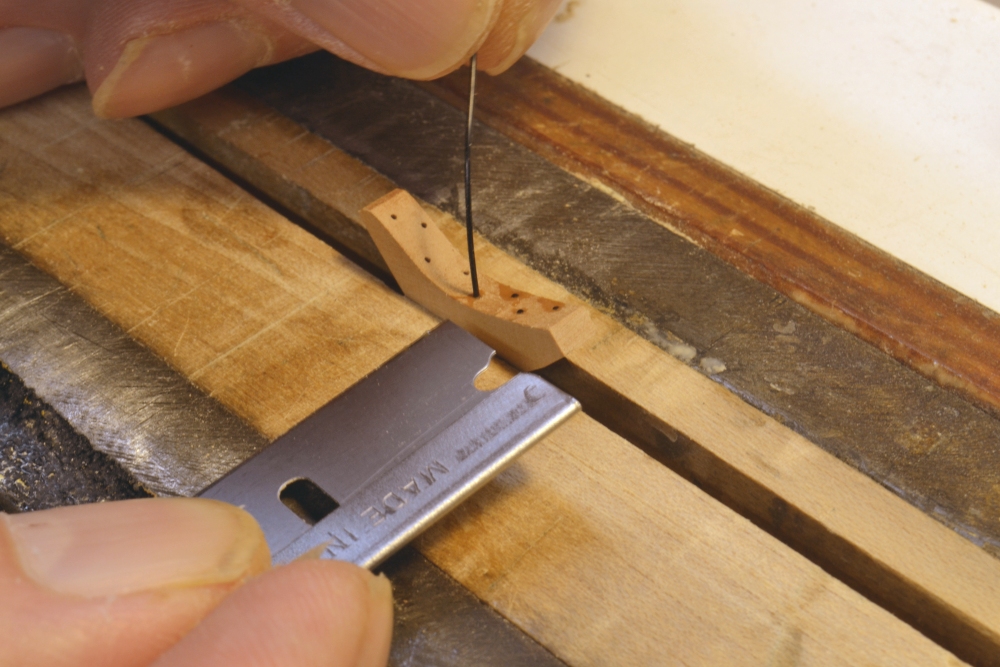
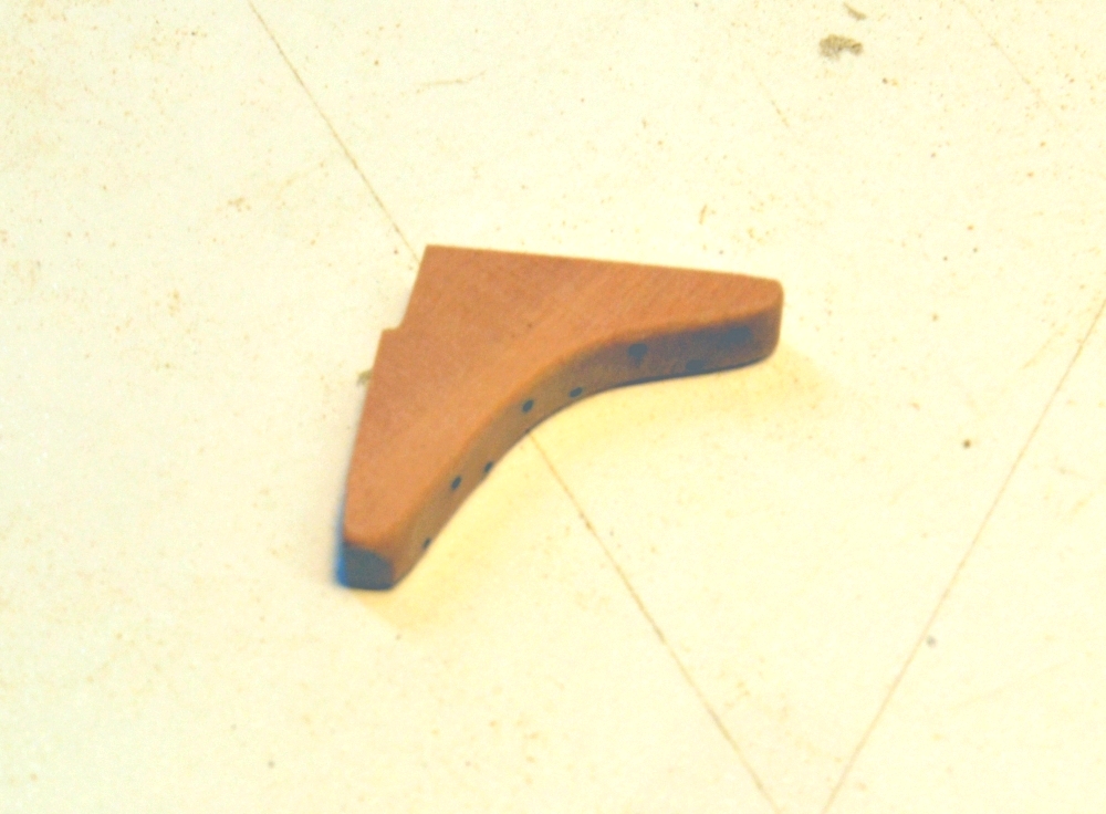
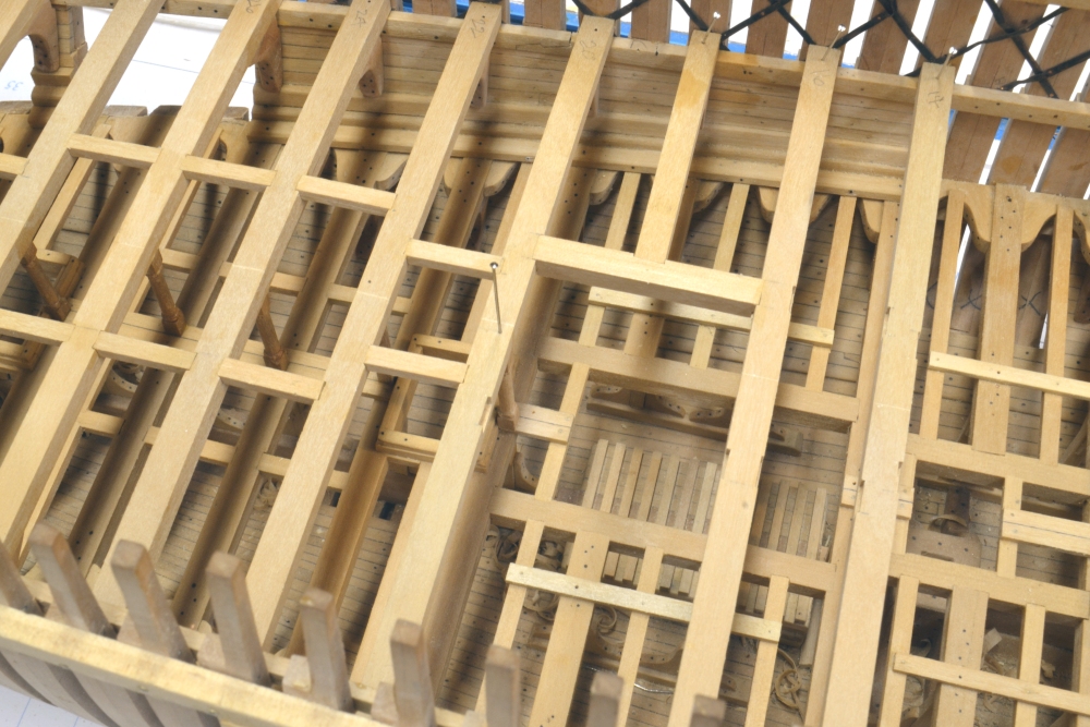
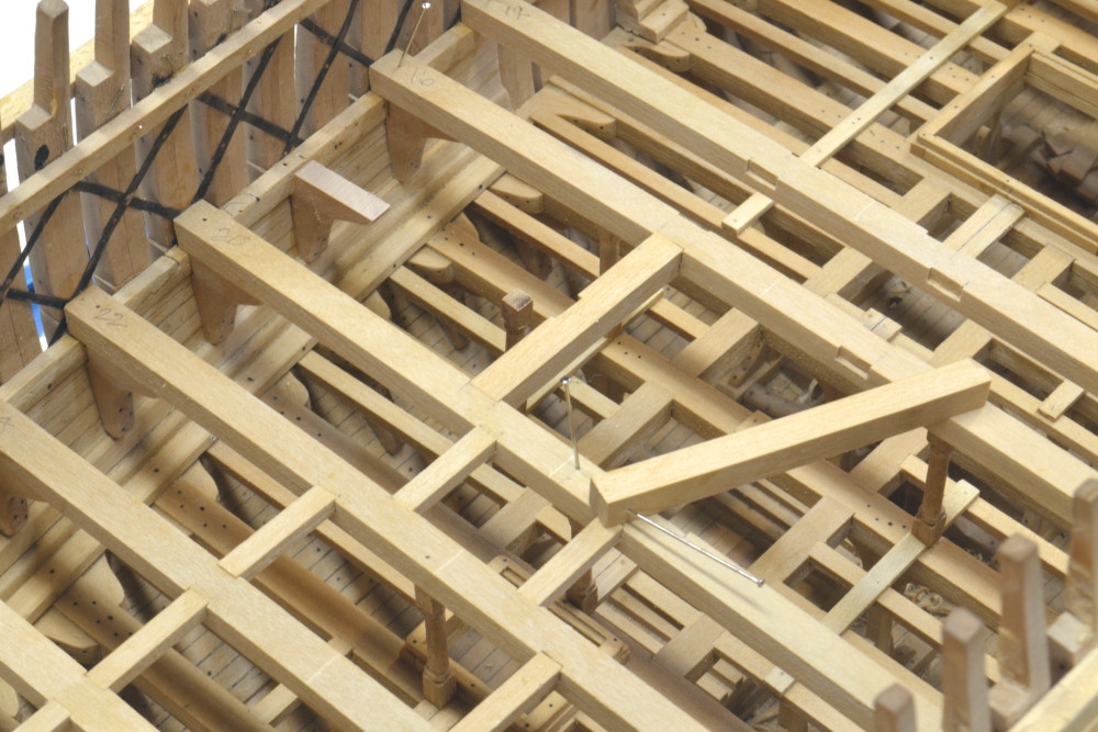
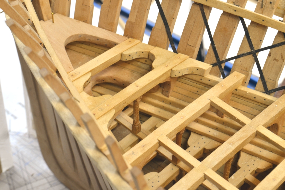
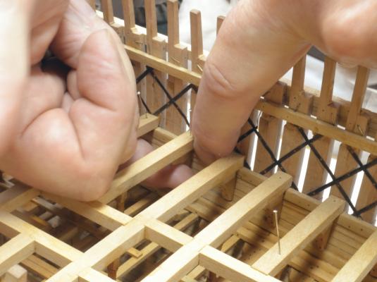
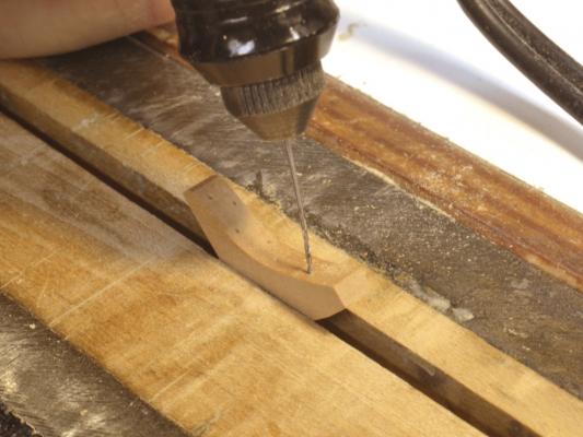
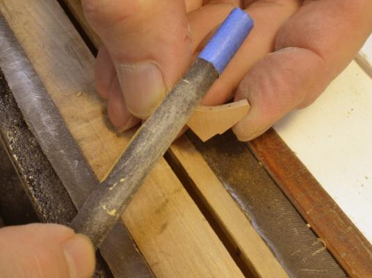
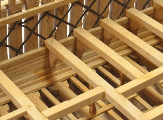
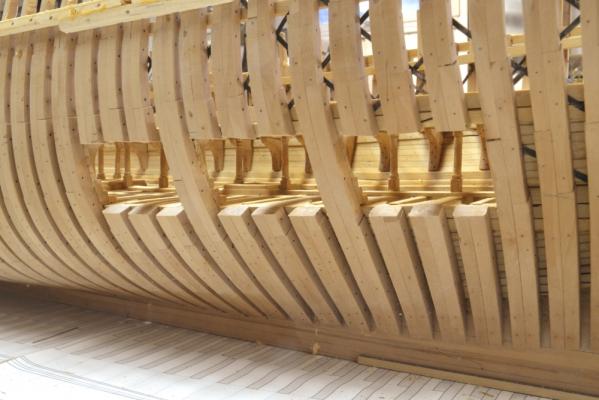
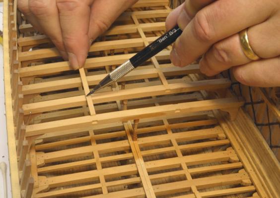
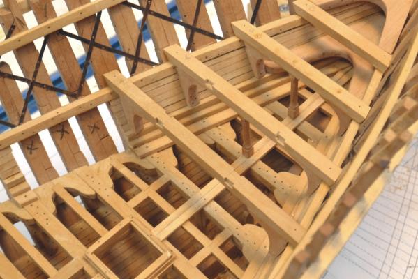
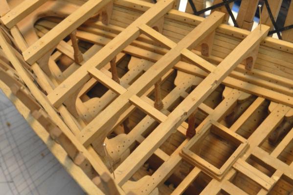
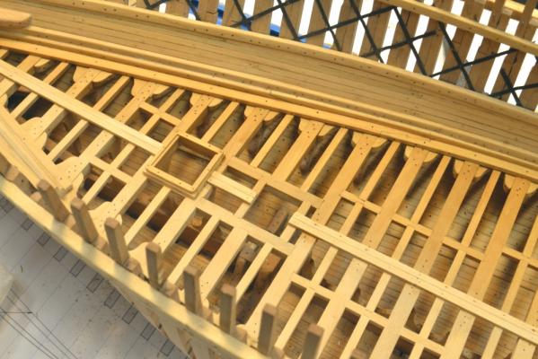
Young America - extreme clipper 1853 Part 80 –Middle Deck Hanging Knee I usually limit the content of these posts to progress reporting. Except for some general comments I don’t usually do step-by-step demos in these. This post is hardly a tutorial, but I am spending so much time on deck beam knees that I decided to focus on making one of those. There are roughly 250 hanging knees and an equal number of lodging knees in the model, so it is hard to ignore this process. I try to follow Remco’s advice on these to treat every part as a separate model, but its not always easy. Four or five a day are my limit. We’re getting down to the wire on the middle deck framing. As the beams get closer, the fitting of the knees requires more contortions as evidenced in the first picture. The subject knee is being fitted under a half beam, so the beams fore and aft are already in place. A few of these knees inevitably end up in the hold during this process. After the knee is cut from one of several generic patterns, it is fitted by trial and error as shown – in and out maybe 6 times. Most of the trimming is done with the disk sander. Once it is fitted , the knee is removed to the vise for bolting and final finishing. In the next picture the bolt holes are being center marked. There were 15 to 18 1” iron bolts securing each knee. I am aiming for about half that number – sometimes less - in the model. In the next picture the bolt holes are being drilled. This is a number 73 (.021”) drill to slip fit a bolt of 20 lb test black monofilament. This is equal to a 1 ½” head at 1:72 – about the size of a riveted 1” bolt head. In the next picture the monofilament bolt is being glued in with CA glue. It will be sliced off flush with the razor blade. The excess glue and any protruding monofilament is then filed off with a coarse rounded file. This surface is then sanded with 220 and 320 grit paper on dowels. In the next picture the corners are being rounded off. Finally, the finished knee. Note the notch for the deck clamp. The last picture shows the glued-in knee in the center of the picture on the half beam. In a later step, the knee will be further secured with a copper wire bolt inserted and epoxied through the beam and well into the knee from above. Several other simulated bolts will then be installed over the knee in the beam. Another copper wire bolt will replace the pin in the picture. At this stage only one knee is left to do – on the half beam missing from the picture. Then on to the lodging knees and ledges. Ed


- 3,618 replies
-
- 24
-
-
- young america
- clipper
- (and 1 more)
-
Hello, Remco. Lovely work as always. Although I routinely use bamboo for treenails, I agree that the apperance is not always the best as your demo piece shows. Ease of drawing to small sizes is the main attraction I guess. I have used genuine box, but for some reason have not tried castelo. What size are you drawing the castelo to? I may be ready to convert - at least for the open areas. Ed
-
Ah, Micheal - a good use for my underemployed airbrush.
-
Those last few small particles, often wedged in place or in small crevices are the the problem. I have two other methods. The first is to turn the model upside down and shake it - talk about risk. The other is to turn it upside down on he bench and blow the dust out with the shop vac. With the limber area open between frames, his works well, even with the model upright. I have also used aerosol cans used or cleaning electronics, but sometimes the propellant condenses on he work. Compressed air frman oil free compressor - like an air brush compressor - with a small diameter tube might also be good. A small diameter dowel with a bit of two faced carpet tape on the end also works well. For steel wool particals, there's nothing like a pencil magnet. Its almost impossible t keep this stuff out. I believe I may cover the open deck areas with masking tape later for the rigging work, but this too ca be a problem. By theway,is anyone besidesme havin a problem wit this text box dropping characters? This sentenceis an exaple. I almost always have t go back and add dropped characters and spces. I do enoug typing t know its not me and I do not have this problem with any other applicatons. Ed
- 3,618 replies
-
- 3
-
-
- young america
- clipper
- (and 1 more)
-
Thanks, everyone. As always, your compliments are very encouraging. I wish the work were a little more varied, but at this stage there is a lot of deck framing to do and much of it looks alike. I am beginning to appreciate that it is a large ship - but she was a beauty and I am glad to have chosen it for a model. Dave, the main thing I'm thinking when looking down through all those beams is - how did all that debris get into the hold and will I be able to get it out? Cheers, all. Ed
- 3,618 replies
-
- 1
-
-
- young america
- clipper
- (and 1 more)
-
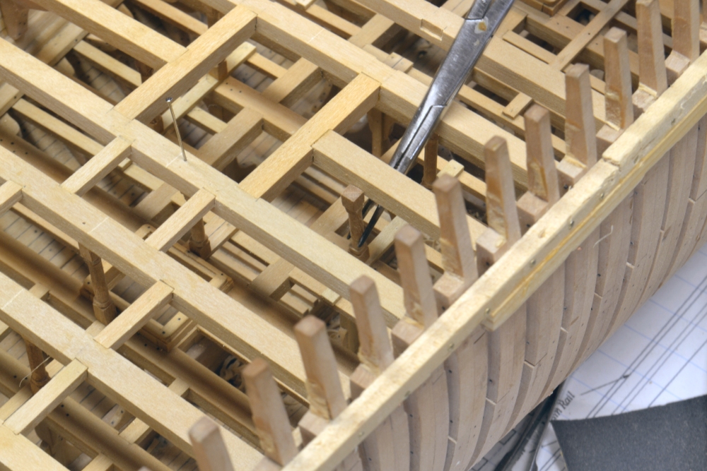
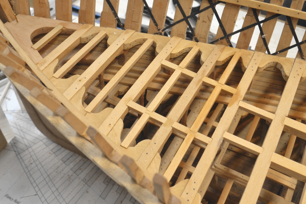
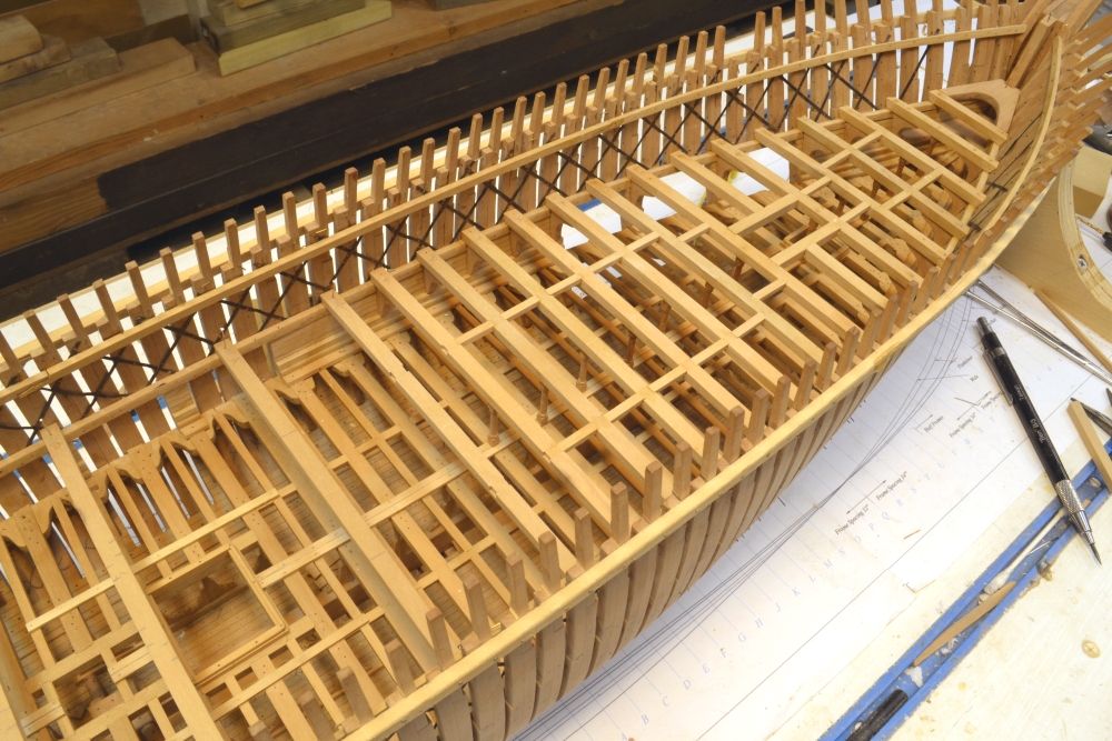
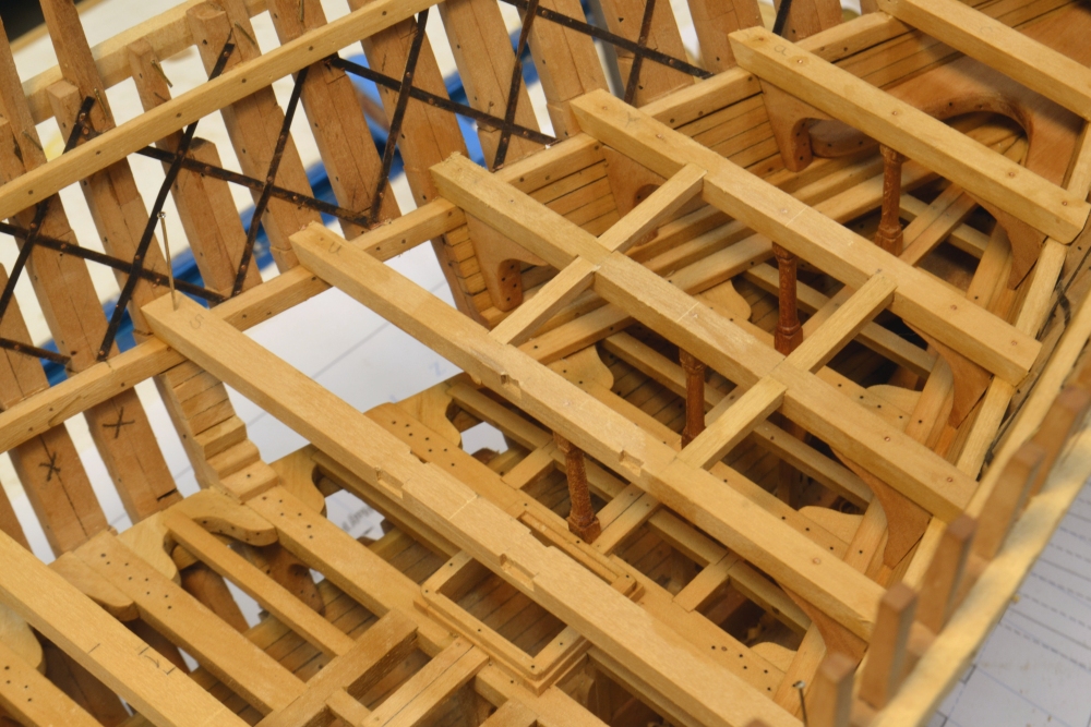
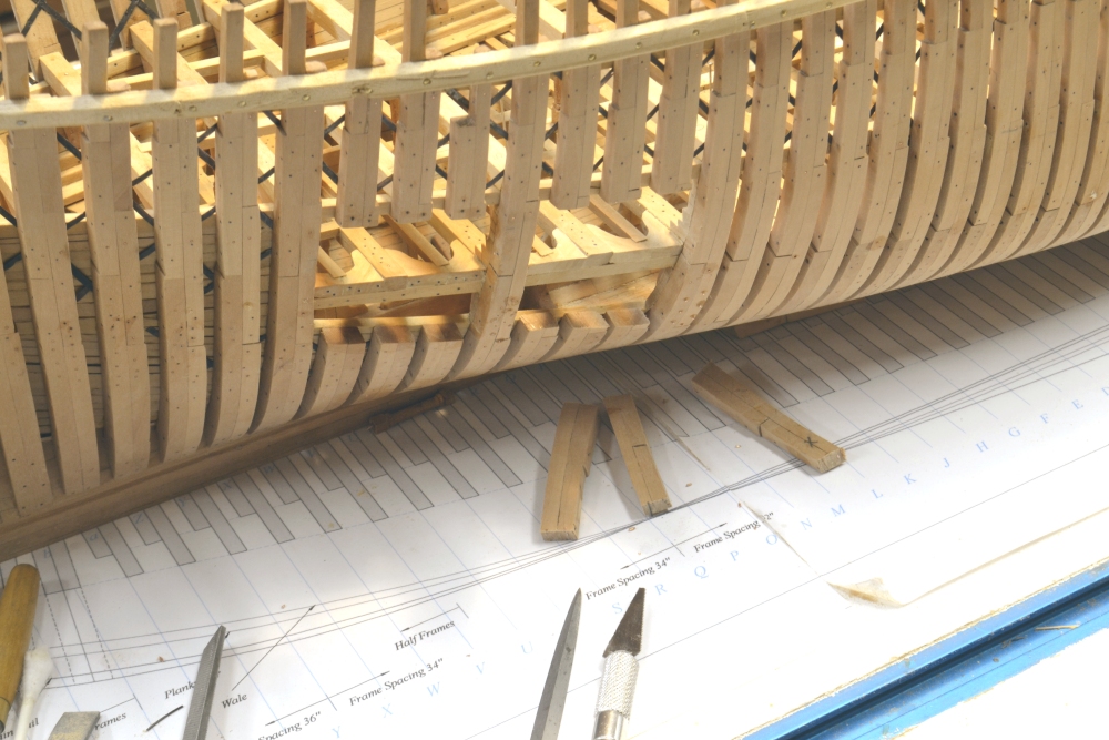
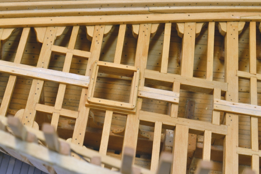
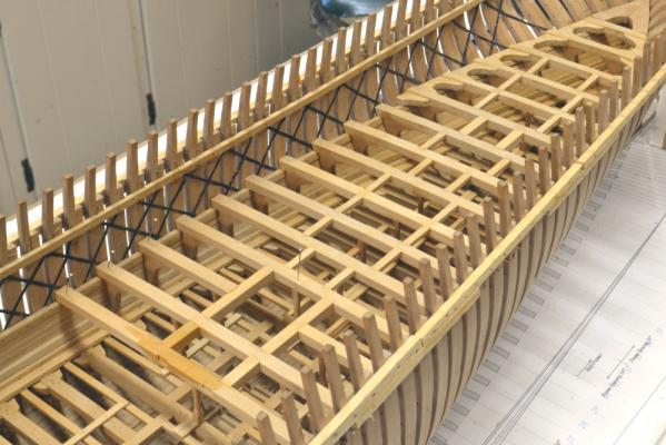
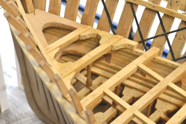
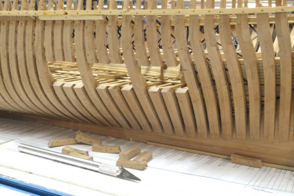
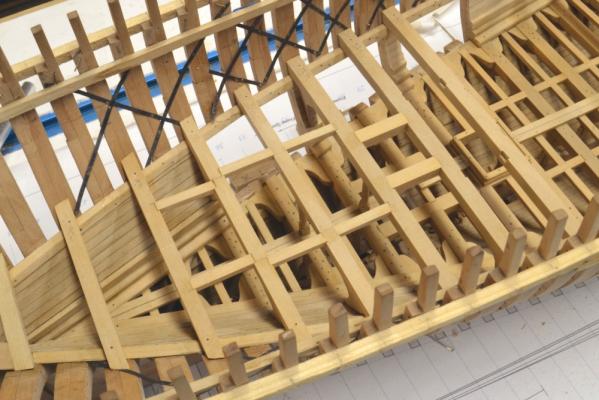
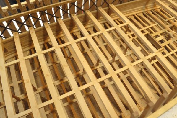
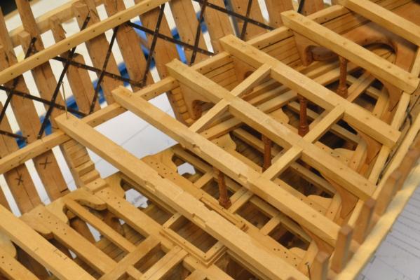
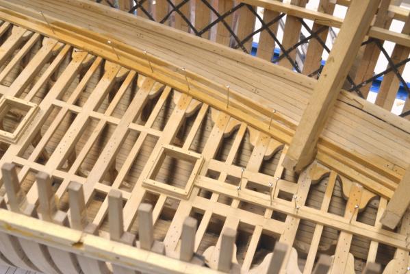
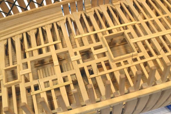
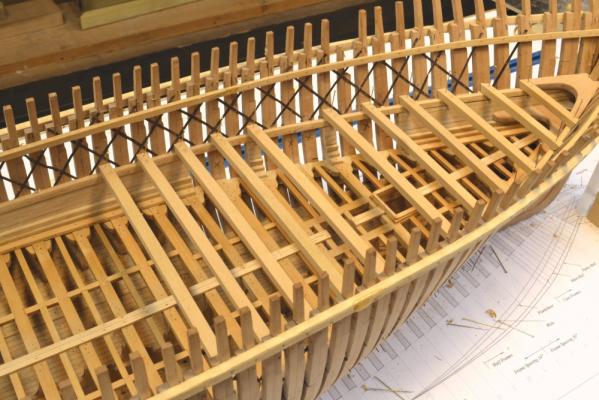
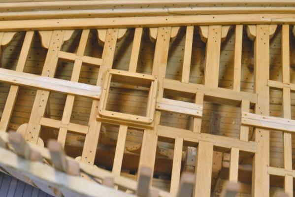
Young America - extreme clipper 1853 Part 79 –Middle Deck Framing continued The middle deck framing continues. The first picture shows the opening for the large water tank being framed. The header between beams 16 and 20 has been installed and the half beam at 18 fitted temporarily. The large 6000 gal fresh water tank will fill most of the space in this opening from its base in the hold to just under the main deck beams. In the next picture the hanging knee and the pillar under the half beam are in place and the half beam is ready to be installed. The smaller 2000-gallon water tank will come up to just below this deck . Its top will fit in the currently unframed opening between beams 16 and fourteen in the upper right of this picture. In the next picture the pillar under the starboard half beam is being fitted for size. The next picture shows this area looking down and aft. The paired pillars on either side of the tank opening can be seen in this picture. The next picture shows the extent of framing aft of midship completed to date. One full beam and two pairs of half beams remain to be fitted – then the lodging knees and ledges. Some of the lodging knees have been fitted at the aft end of the deck. The last picture shows the stern view opening. As mentioned earlier, this one shows only the space between the middle and lower decks. The exposed ends of the frames have been fairly well squared off in this picture, but there is still finish sanding, etc to be done. The outsides of the frames have been faired, but final sanding and finishing cannot be done until many more simulated bolts are installed. Those in the picture are bolts for the deck clamps and for the heavy internal bilge ceiling. Bolts for deck knees have not been installed yet. Ed


- 3,618 replies
-
- 26
-
-
- young america
- clipper
- (and 1 more)
-
Thas, everyone. Ian, it was painful to cut through those frames, but one must make choices and the alternative was for everything to be buried out of view forever - as was the case with much hard workon Naiad's magazine,et al. Dave, by your new avatar it appears you have given up pirating. Maury, I am pleased with the ports. There is more work to do in cleaning them up, but I need to invert the hull for that. Druxey, believe me, no one would try to pass these scraps off as their own work, but thanks for defending my rights to them. Spent most of themorning sharpening chisels so no measurable progress today. Ed
- 3,618 replies
-
- 4
-
-
- young america
- clipper
- (and 1 more)
-
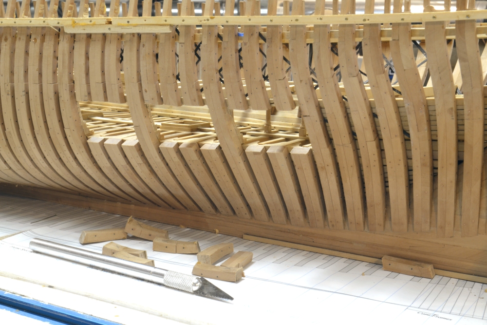
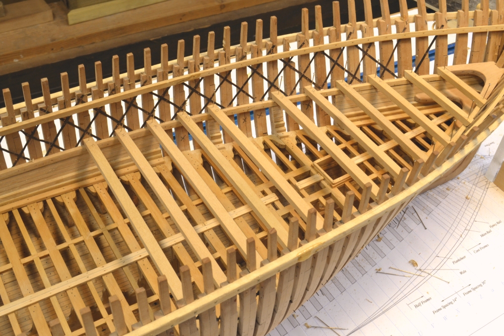
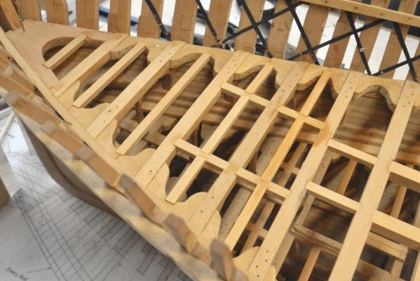
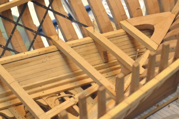
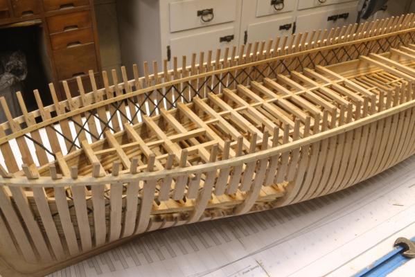
Young America - extreme clipper 1853 Part 78 –Middle Deck Framing continued It has been almost another two weeks since the last post. Again, the work is pretty repetitive – a carbon copy of the lower deck – but with fancier pillars. Work continues, however. At the bow, as seen in the first picture, the installation of lodging knees has begun. This has provided something of a break in the hanging knee/beam work going on aft. In the next picture lodging knee installation has been followed by the ledges and also the bolts associated with each beam. Meanwhile, in the next picture, 240 feet aft, the deck hook at the stern has been fitted, followed by the first few beams. The deck hook was made in two pieces to save Swiss pear trees. That center seam will be covered by central deck planks as was done on the lower deck. As middle deck beams were installed, the aft view ports could be cut, as shown in the next picture. There is only one level in view in these aft openings because the rising line is quite high this far back, so there is nothing much to see below the lower deck. The last picture shows the current state of the middle deck beam work aft. The work goes fast when I stay with it, but this time of the year there is much else to do. Ed
- 3,618 replies
-
- 32
-
-
- young america
- clipper
- (and 1 more)
-
Hello Mark, The pin holes that set the location of the pillars at the bottom are drilled into the centers of the planks on either side of the centerline and on the centers of the beams below. Then, when the pillar is fitted on the bottom pin the top is adjusted by eye wen glued - to the others and to be vertical in the fore and aft direction - again by eye. After the glue has set,the top pinholes are drilled down through the beam above into the top of the pillar. Nothing too fancy. Ed
-
Thank you all for these comments and "likes" - most appreciated. Ed
-
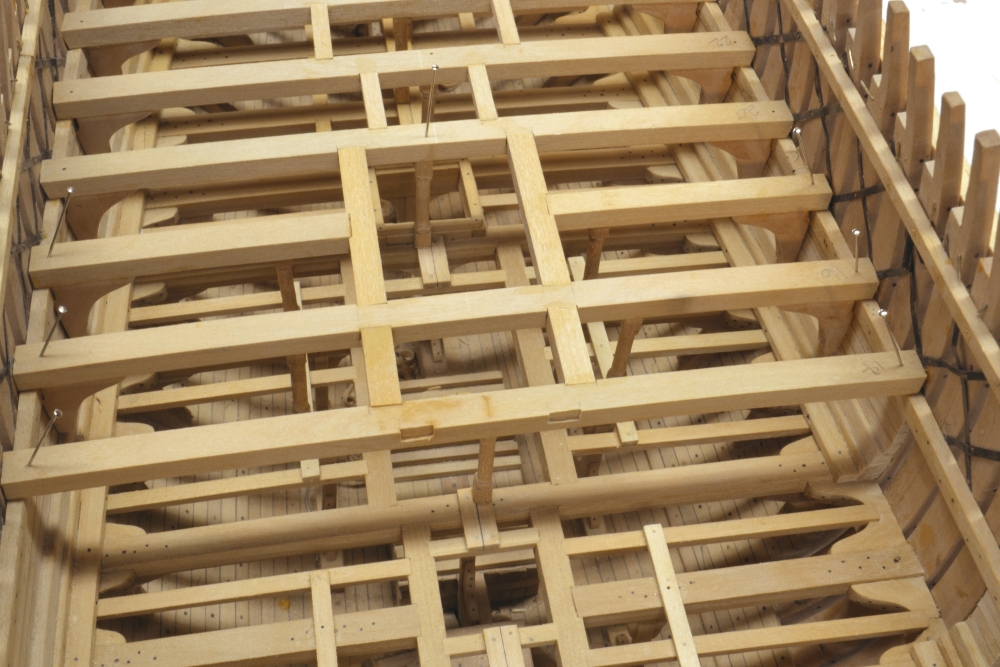
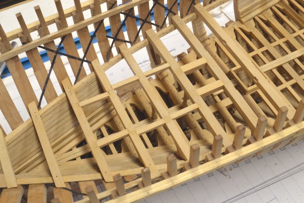
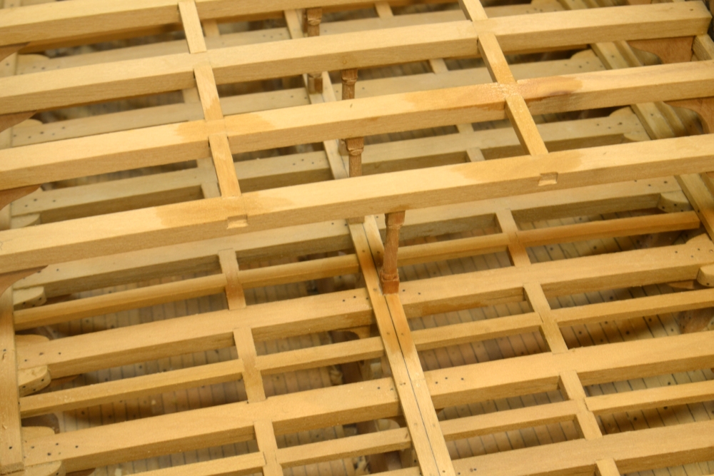
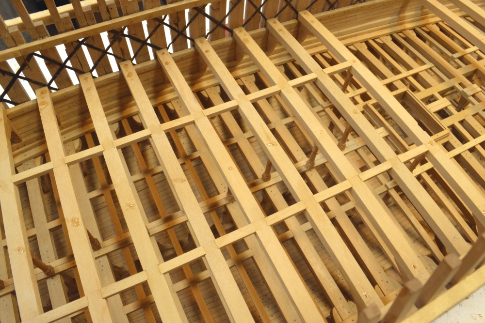
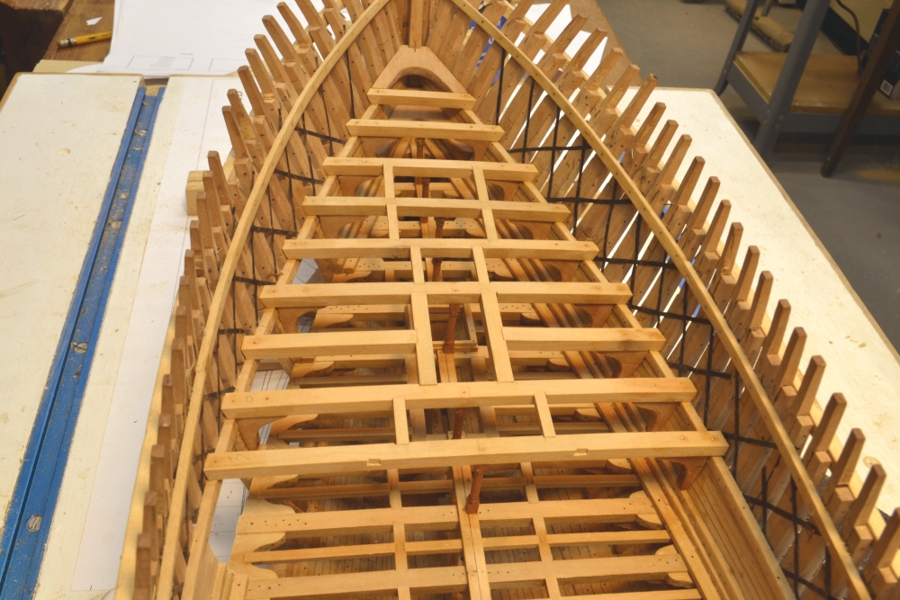
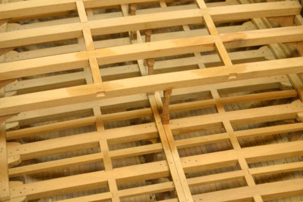
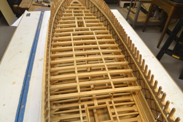
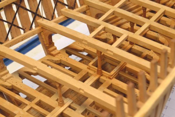
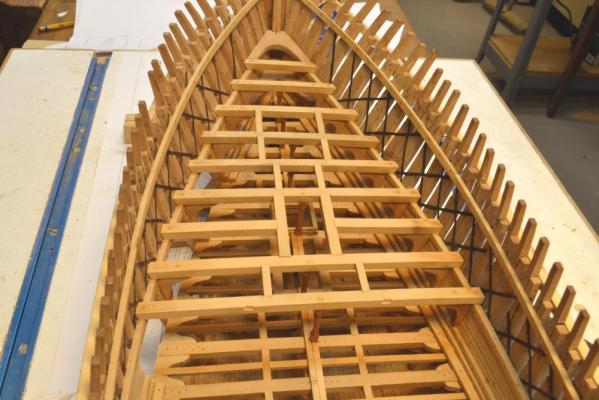
Young America - extreme clipper 1853 Part 77 –Middle Deck Framing continued It has been almost two weeks since the last post due mainly to the similarity of the lower and middle decks – not a lot of new stuff. However, the middle deck framing is proceeding quickly – perhaps it’s the learning curve. The first picture shows beam installation progressing from the bow aft. The beams, hanging knees, pillars and carlings are all being installed progressively – leaving the lodging knees and ledges until later. This has helped with the pace. The next picture shows a carling being fitted. The carling seats were cut out at the bench based on marks made on the model with the beams pinned – so the carling fitting goes very fast. The next picture is a close up of the carlings for the above beam. The wet spots are from washing off excess glue. The pillars are set at the bottom on a piece of wire fit into a drilled hole – after adjusting the length to fit. They are then glued top and bottom. Wire “bolts” into the top will be added later. The pillars were offset to permit long through bolts that were used to hold the beams tightly when side hull stresses would tend to separate them. In the next picture wire “bolts” have been epoxied through the beams at the ends and into each pillar. The bolts at the very end pin the beams in place. The bolts just inside of those are inserted at an angle, down into the hanging knees to give their connection additional reinforcement. The last two pictures show the current status of the work on the middle deck. The work will now continue from the stern forward. It is easier to do the small end beams starting from the stern deck hook. Ed

- 3,618 replies
-
- 36
-
-
- young america
- clipper
- (and 1 more)
-
Thanks, Guy, for your continuing and loyal support - and also to those who commented or "liked" since the last post. I am not on vacation, but have been consumed with some other things - mostly related to the model - drawings patterns, rigging schedule, etc. The middle deck is also long a quite like the lower, so there is not much new to show. However, I willtry to get the next part up soon. Thanks, again. You all keep me motivated. Ed
- 3,618 replies
-
- 1
-
-
- young america
- clipper
- (and 1 more)
-
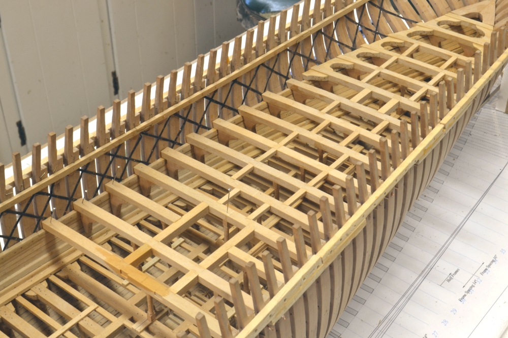
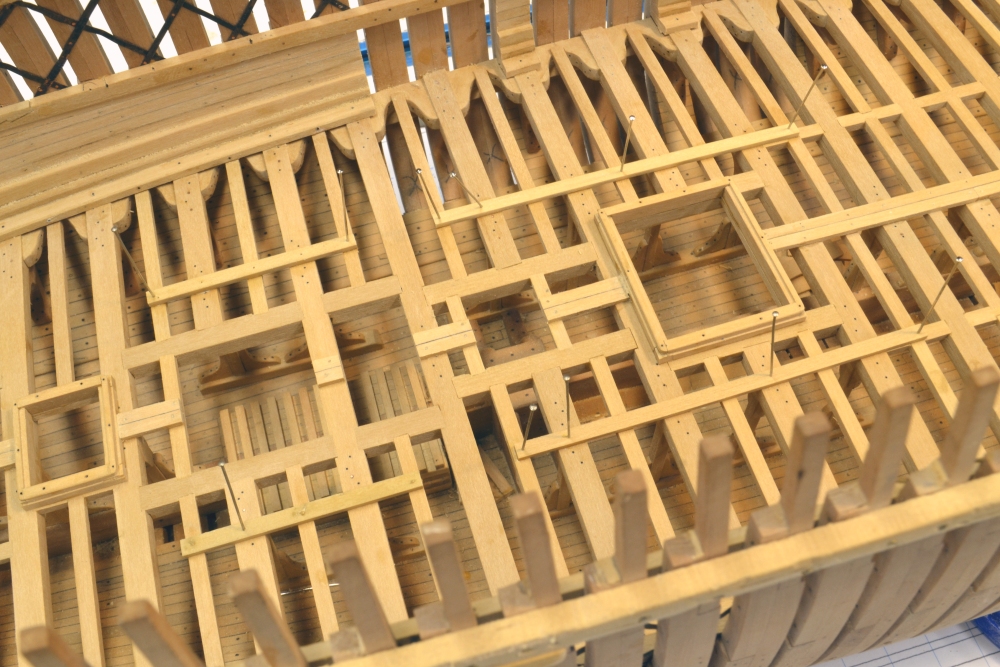
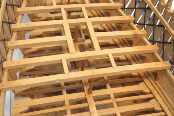
Young America - extreme clipper 1853 Part 76 –Middle Deck Framing Since the last post eight middle deck beams and one pair of half beams have been installed – along with their hanging knees and pillars. Lodging knees will follow. The first picture shows the first four beams and two pillars installed. The beams are glued bolted to the clamps with copper wire - epoxied in. There will also be copper wire bolts through the beams into the tops of each hanging knee for extra strength. The pillars are reinforced with wire into the beams top and bottom. The next picture shows the first of the carlings installed. These are going in after the pillars to leave space for fitting those. In the next picture, the next beam has been glued in and is awaiting its hanging knees. Once the beams are in place to support the clamp over the view openings, they can be cut out – as in the above picture. The next picture shows the first two of three openings cut into the forward view area. The next picture shows those openings from the inside. This area is now ready for the headers around the fore mast and the half beams to those headers. The areas below the middle deck are having wax finish applied progressively as the work above is finished. In the next picture the two headers and half beams have been installed astride the fore mast opening, The beam, knee and pillar bolts mentioned above were also in when this picture was taken. The last picture shows the current extent of the work completed. This work is going faster than the lower deck framing, mainly because there are no knees on the pillars. Patterns for the middle deck knees were also lofted more carefully using a different process - meaning the initial fits are better. Also, deferring the lodging knees is probably more efficient. Ed

- 3,618 replies
-
- 33
-
-
- young america
- clipper
- (and 1 more)
-
Thanks for the pictures, David. I am sure that at the prevailing freight rates she was jammed to the gun'ls. SawdustDave, I can't answer your question. You need an entymologist for that one. But related to that, unlike many other aging clippers, I do not think Young America ever had to suffer the indignities of the detested guano trade. However, my minimal undrstanding of that is that the ships were moored under the chutes and basically filled up. Ammonia cocktail, anyone? Ed
- 3,618 replies
-
- 1
-
-
- young america
- clipper
- (and 1 more)
-
Thanks, again, for the comments. On the cargoes, Guy has it quite right - anything that the market demanded - in Gold Rush California that meant just about any saleable commodity. The hold, lower and upper decks were basically jammed with cargo, the hatches sealed and caulked and usually no one went below the main deck until it was time to unload. She did make one run from Hong Kong to Manila with 800 coolies aboard and in her last years under Austrian ownership she carried a lot of Pennsylvania crude oil to Trieste. Attached is a cargo list from her October 1854 voyage from NYC to SF that will give you an idea of typical cargo - if you can decipher it. Right click and open link to magnify. Ed

- 3,618 replies
-
- 8
-
-
- young america
- clipper
- (and 1 more)
-
Young America - extreme clipper 1853 Part 75 – Lower Deck Finishing/ Middle Deck Beams The finishing touches on the lower deck are finally complete. The first four pictures show the last stages of the work. The first picture shows the last section of binding strake being installed. As usual the dark area are wet from washing off excess glue. The two central planks aft of the after hatch are also being glued. The opening for the mizzenmast will be cut later. The next picture shows final planking around the main masts. The planks astride the openings are need for the pillars. There is not much planking on this deck – to maximize visibility of the hold. After this final planking, all of the remaining treenails were installed and all of the copper bolts blackened in preparation for finish. In the next picture the starboard side framing has received the first application of wax solution. The side planking is left unfinished so the hanging knees can be glued. The next picture shows a closer view above the forward hatch after the first coat of finish was applied. The planks have been cut for the fore mast opening and left unfinished for later gluing of the pillars. The next picture shows fitting of the middle deck beams in progress. These have been cut to size, shaped at the ends to match the frames and pinned in place temporarily. In the next picture all of the full width beams have been pinned in place. Ed
- 3,618 replies
-
- 31
-
-
- young america
- clipper
- (and 1 more)
-
Sorry to be confusing in flipping back and forth between real and scale dimensions, Dave, I almost always use actual historical feet and inches to express ship or ship part dimensions so you can convert to scaled, model sized dimensions in cm or ft-in as you prefer. These ships were built in the English system of measure - not that it matters in scaling. However when talking about tools - like the 2" saw blade - or even the thickness of the starting block for the knees - 1" thick - I will usually use actual feet and inches, since it makes no sense to say I'm using a 12 foot diameter saw blade on my Preac - or even - a block of pear 6 feet thick. When expressing some model dimensions, like the finished siding thickness of the knees, I will sometimes indicate both the actual, unscaled plus the scaled- as in the last post - 12"(.167"). The .167" is the 1:72 equivalent of the unscaled 12" - in this case to better describe the actual size of the piece being sliced off. I hope this explanation has not confused you even more. I do understand why it might. The most frequently used tool in my workshop is the 1:72 conversion chart that converts real unscaled dimensions to scaled dimensions. A copy is attached. Rulers, English or metric are the least used. Ed 1to72 Inch Conversions.pdf
- 3,618 replies
-
- 4
-
-
- young america
- clipper
- (and 1 more)
-
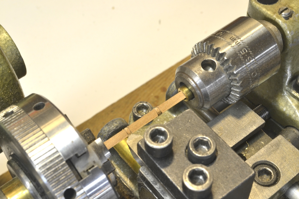
Thank you, everyone - for the comments, "likes" and the questions. As for the questions: Pops, I'm afraid its all book learning and practice over 40+ years - a great deal of furniture work, other mdoelmaking and two previous ship models - both on these pages. A close look will tell you I'm no perfectionist, but I am productive. Its a balance for me. Mark, the knees are sliced off on a 2" diameter Preac table saw using a fairly thin slotting saw blade. Because of the shape these require two passes, each made with one knee arm up so they can be held from above through the cut. Two push sticks can also be used. This double cut sometimes leaves a visible cut line, which is sanded off. These are 12" (.167") so I usually get 5 from a 1" thick shape. These could be cut individually from a .167" blank, but the method shown saves hours (and sanity). ...and yes, Young America had very beautiful lines - for which I, of course, take no credit. Ed
- 3,618 replies
-
- 3
-
-
- young america
- clipper
- (and 1 more)
-
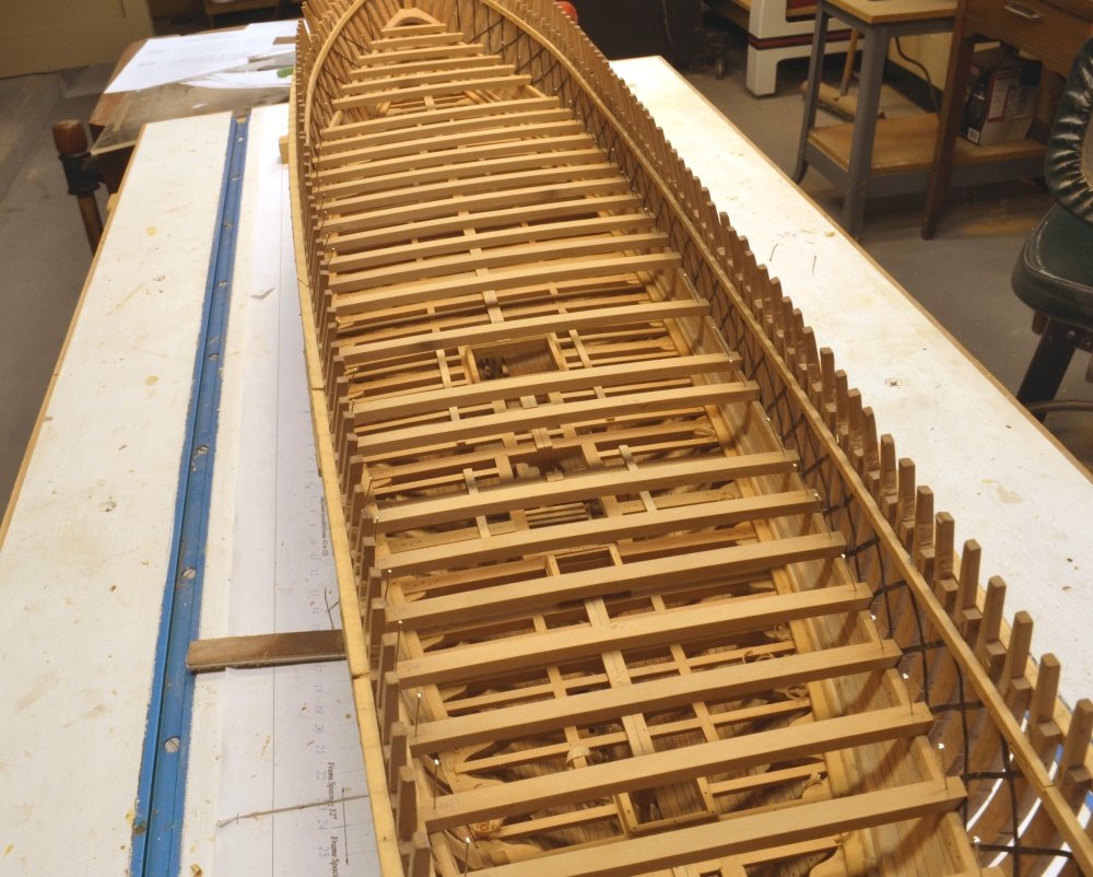
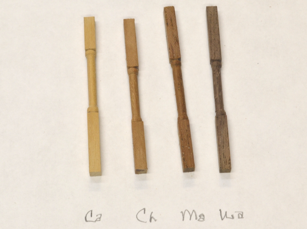
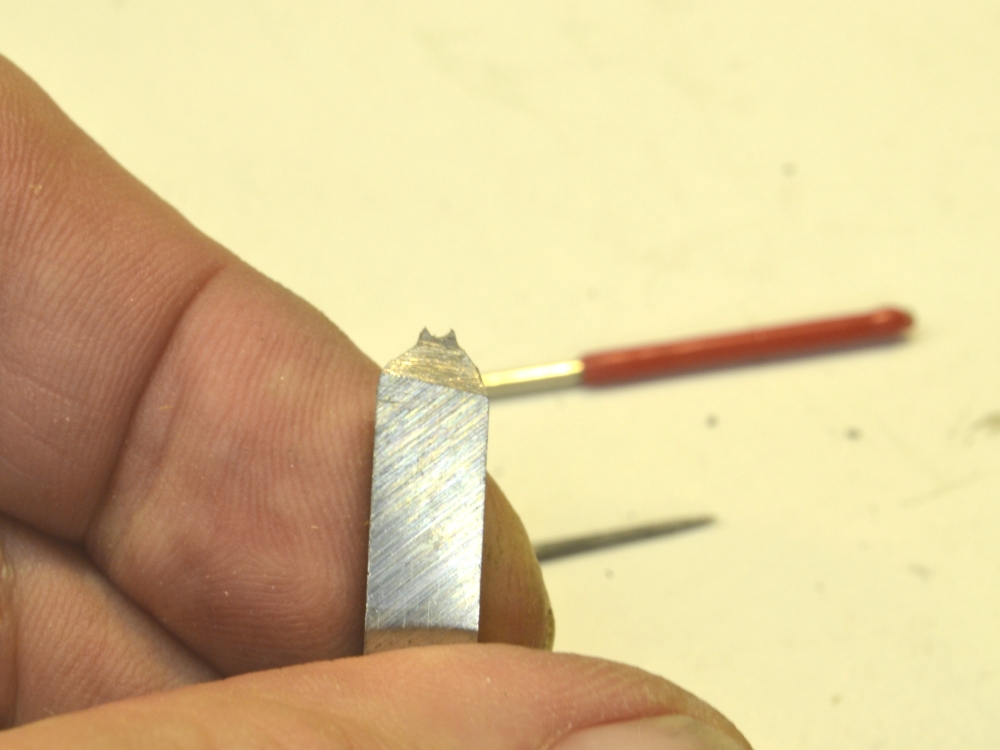
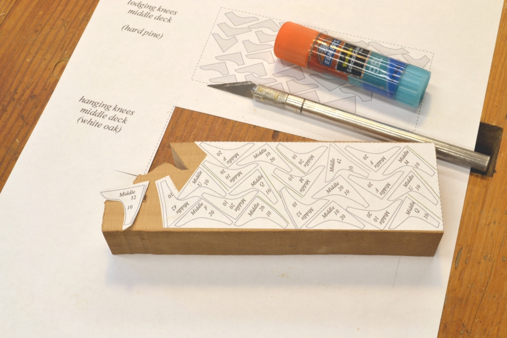
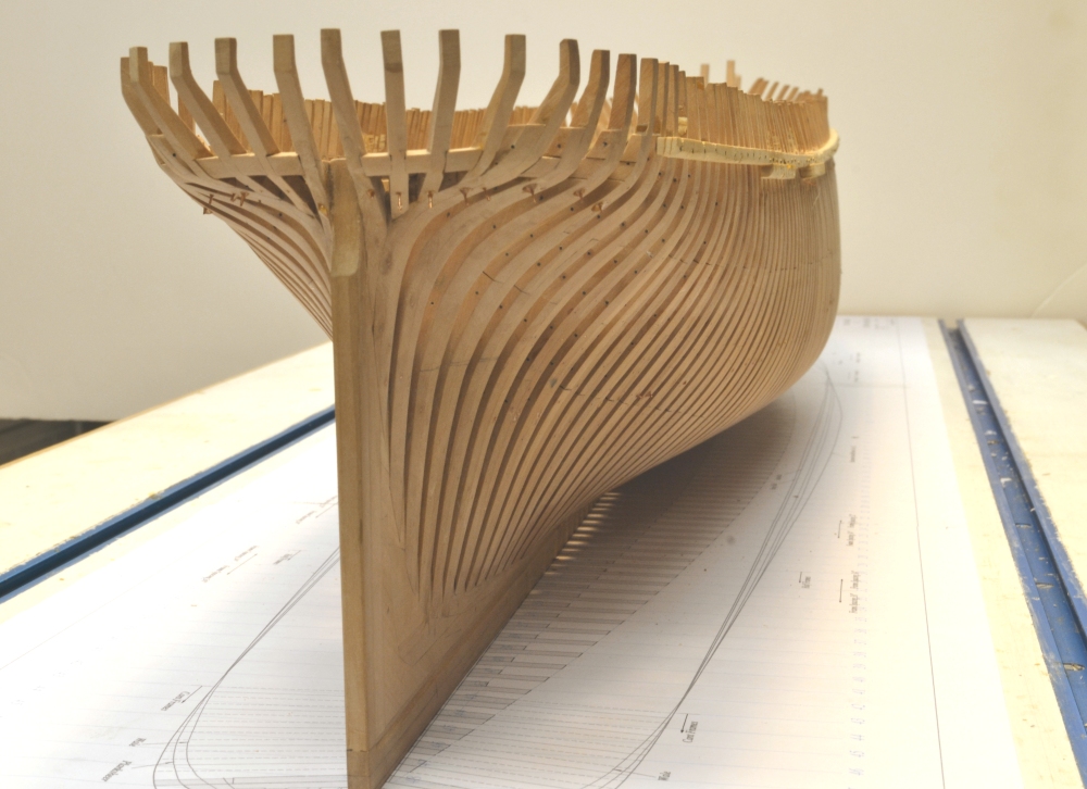
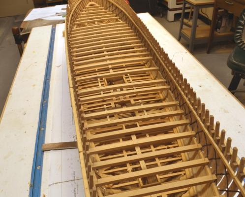
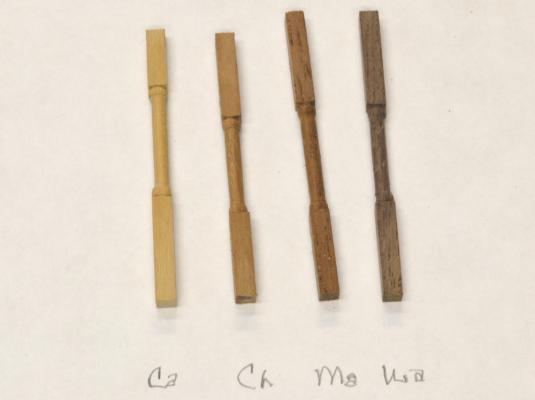
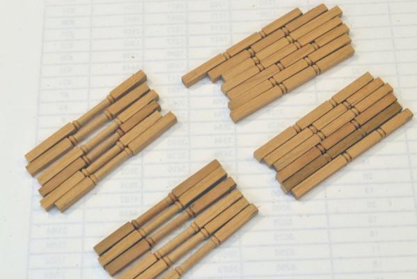
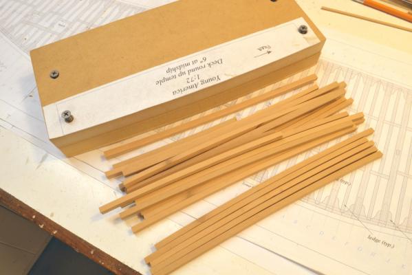
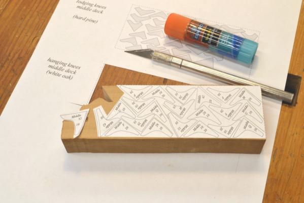
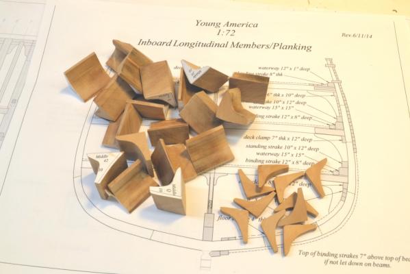
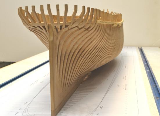
Young America - extreme clipper 1853 Part 74 – Middle Deck Parts Posts to the log have not been as frequent because much of the work has been repetitive. In the next phase – the middle deck – the work will be a virtual carbon copy of the lower deck. Very little work remains to finish the lower deck – mainly treenailing and some deck planking. While that is being completed, parts for the middle deck are being made. In the first picture some sample turned pillars have been made to help me decide on the choice of woods for these. Six dozen are required for the next two decks. Turned pillars above the lower and middle decks were probably black locust – a favorite wood for that application – and for treenails. The four options pictured are, left to right, Castelo, Cherry, Mahogany and Black Walnut. I loved the color of the Honduras Mahogany but the pores are a bit distracting –same with the Walnut. They could be filled but not on these small pieces – maybe for the upper deck rails. So I decided on the cherry. It is slightly darker than the pear I am using for oak members. For the final versions of these a new lathe bit for the beads was required. After quite a lot of fiddling with the shape and the depth of the cut the tool in the following picture was used. The next picture shows the beads on a pillar being turned. The piece is held in a self-centering four jaw Sherline chuck, running on my ancient Unimat SL. The homemade brass adapter for the chuck can be seen in the lower left corner. The cherry square is kept on center inside a close fitting brass sleeve in the tailstock chuck. Cutting depth is set by the brass half sleeve stop slipped over the cross-feed rods – visible just below the cutting tool. The beads are cut first and the piece removed so others can use the same setup. That set up is then changed and the area between the beads turned in about the same way. The next picture shows the first two dozen pillars in progress. Deck beams were also made. The picture below shows the middle deck set before cutting to length. The clamp template in the picture is used on a router table to impart the top of the beam curve – a recycled tool from Naiad – but with a different round up. Once the curve is put on the top of a blank, the beam is parted off and run upside down through the thickness sander. I have described this process on a few earlier posts and it is described in detail in Naiad Vol II. Knees, knees, knees – about ten dozen are needed for the middle deck. Below the pattern sheet for the starter set of hanging knees has been pasted to a pear blank about an inch thick. After cutting out on the scroll saw the 12” thick knees will be sliced off. The next picture shows the pieces after cutting to shape with some ripped to size. The shape of these knees will need to be refined to fit each location – from about eight basic shapes. Finally, the out-of-date drawing on the shipway board was replaced with a new one with latest revisions - and is it clean!. The picture below was taken before setting up the end supports – to give a good view of the stern hull lines. Ed


- 3,618 replies
-
- 37
-
-
- young america
- clipper
- (and 1 more)
-
ancre LE BONHOMME RICHARD by Jeronimo - FINISHED
EdT replied to Jeronimo's topic in - Build logs for subjects built 1751 - 1800
Incredible work, Karl. Absolutely beautiful. Ed- 662 replies
-
- 1
-
-
- bonhomme richard
- frigate
- (and 1 more)
-
Guy, your approach sounds like mine - out of the scrapbox, cut to fit the situation,then usually back into he box.
-
Having done a photo-etch design for the Naiad stove, its clear that PierLuigi's work is in a different league. IfI were toput his stove in a model the forecastle would have to be left off to display it. Beautiful, meticulous design and modeling. Ed
-
Mark, if your wedges are made as beautifully as your other tools, mine would be unrecognizable beside them. I tend to cut mine on the fly - often after applying glue. But the subjest warants some thought because they have many virtues as holding devices. One of the things I was thinking about was opposed sets - to bridge wider spaces - also laid parallel to the planking. Maybe a common angle for all, so they could be used interchangeably. Hmmm. Ed
-
Extraordinary work as always, Mark. Your precision always knocks me out. Ed