HOLIDAY DONATION DRIVE - SUPPORT MSW - DO YOUR PART TO KEEP THIS GREAT FORUM GOING!
×


EdT
-
Posts
2,213 -
Joined
-
Last visited
Content Type
Profiles
Forums
Gallery
Events
Everything posted by EdT
-
Thank you, Salvatore. That is truly beautiful work. I'm very envious. A masterpiece - certainly at 1:60. Ed
-
Thanks, everyone for the comments and all the "likes". Allan, wedging seems to be the best way to tight joints if it can be done. My wedges are usually cut "just-in-time" so they a pretty ad hoc. It may be worth some thinking to develop a better set of wedging tools. For example, they way they are cut sometimes leaves grain that doesn't allow easy wedging. There is also the issue of too much space to allow wedging. Often clamps are also needed to get the planks tight to the frames - especially true with the iron strapping. As you say, sizing of planks - breadth and thickness is also important. Its probably best to cut the fully supply of planks at the start so tools do not have to be reset when a new batch is needed. Always lots of "process development" to do. Ed
- 3,618 replies
-
- 1
-

-
- young america
- clipper
- (and 1 more)
-
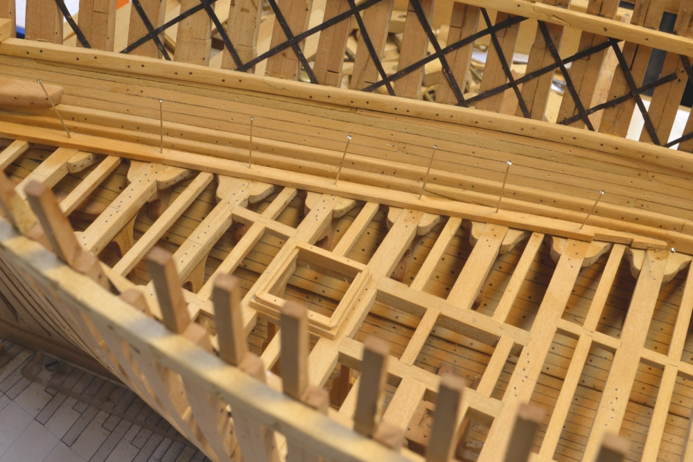
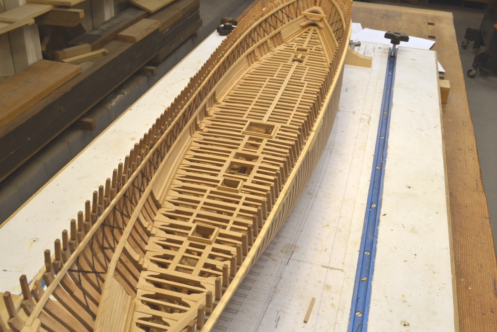
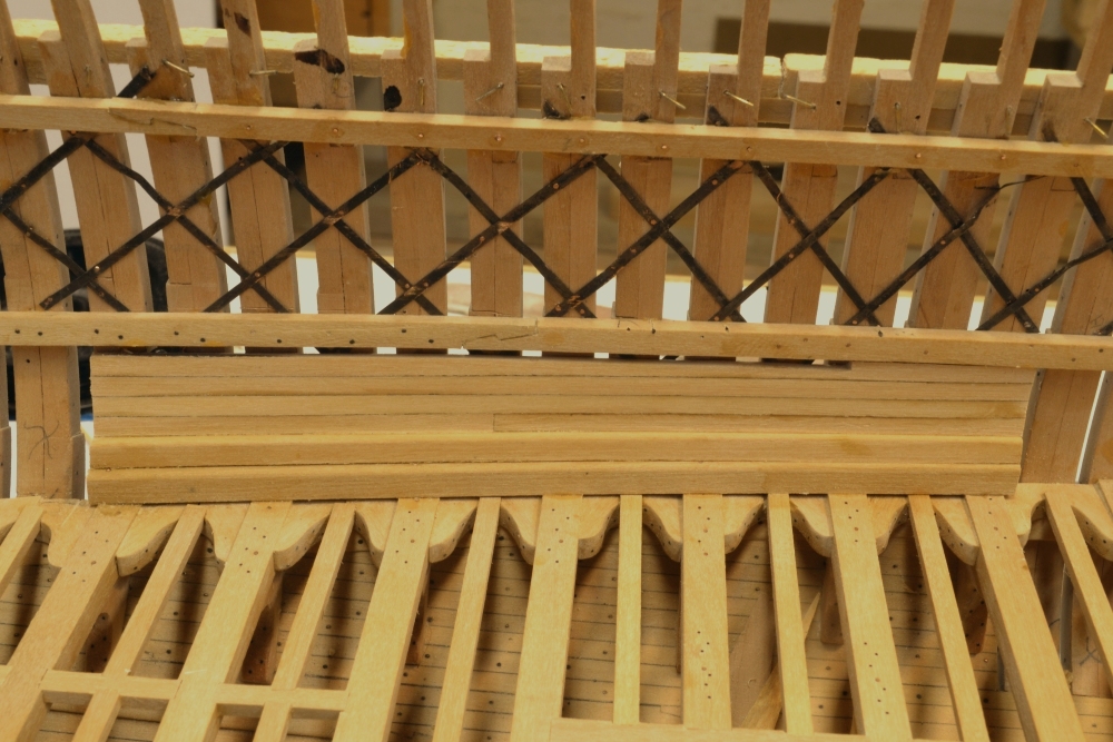
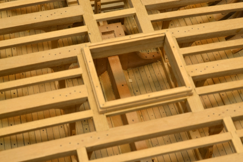
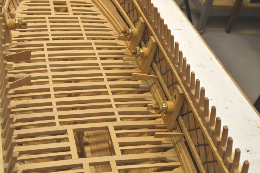
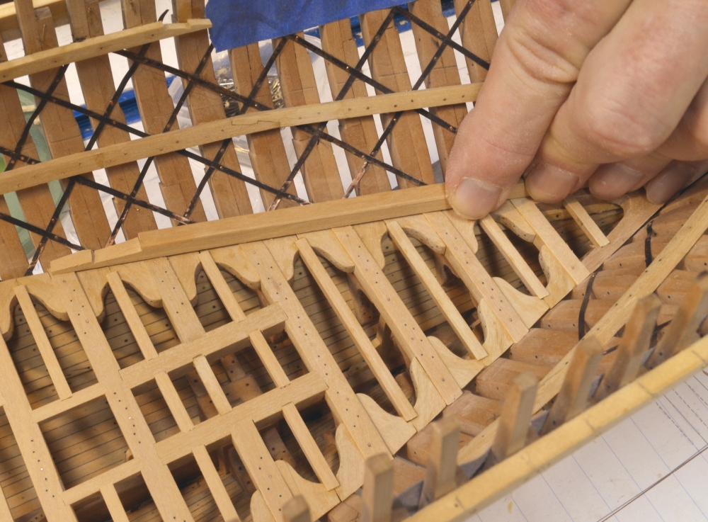
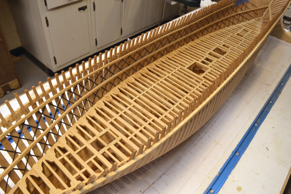
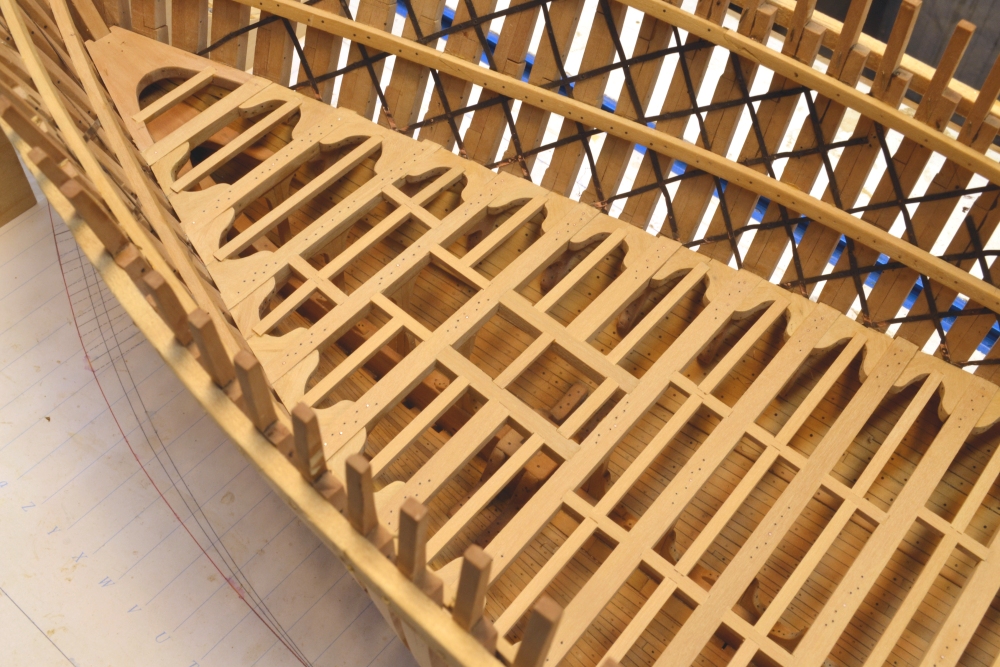
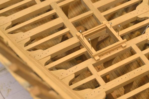
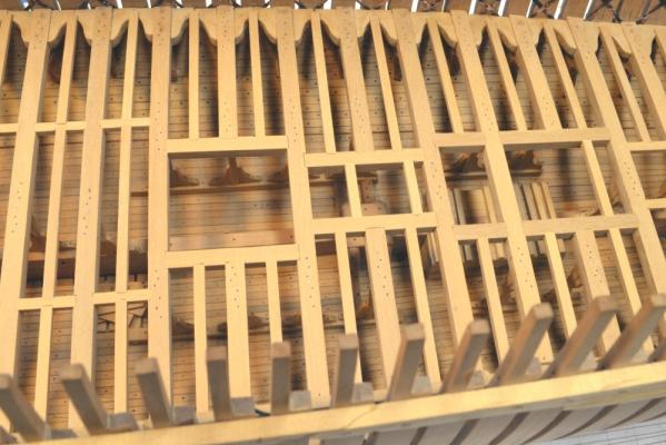
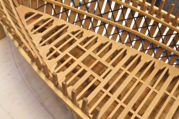
Young America - extreme clipper 1853 Part 73 – Lower Deck continued Work continues on the lower deck. In the first picture a forward section of binding strake is being glued in place held by pins. These structural strakes were often let down on the beam by an inch or so, but because this depth is so small at this scale I did not score the beams and merely reduced the depth of the strake by an inch. As with many details, Young America’s exact configuration is unknown. The binding strakes are bolted into each beam and horizontally into the waterways. Inside these strakes were margin planking – wider planks that allow the ends of forward planking to be cut into them. I will not be installing these on the deck – to leave the ends of the lodging knees visible from above. In the next picture the next section of binfding strake is being installed. Planking on the centerline is in progress. This planking is 3 ½” thick. I made these 7” wide. These are required as bases for the middle deck pillars. I have not yet decided if any planking beyond the two central strakes will be installed on this deck. The next picture shows further work near the bow. The fore hatchway is complete including its bolts. Although not very visible due to sanding dust, the treenails and bolts for all this work have been installed. Next is a picture of the port side forward. There will be no ladder ways into the hold. These would probably have been movable and taken up after the cargo was loaded – and before the hatches were sealed for the voyage. This gives a pretty good idea of the forward view port. The unplanked frames will be removed below the middle deck clamp down to the lower futtock heads – when I summon the courage to cut them out. The next picture shows the port side aft. The aft view port will only extend from the top of the lower deck clamp to the underside of the middle deck clamp. Next are two pictures showing most of the hull at its current state – i.e. today. Once the remaining bolts and treenails and the few remaining bits of binding strake and central planking are installed, I can move on the middle deck. Ed


- 3,618 replies
-
- 32
-
-
- young america
- clipper
- (and 1 more)
-
E&T, The use of terms like "fir" and "pine" leave much to the imagination. Variations between species within these broad terms are considerable. For example Douglas fir vs. the softer Balsam fir - or Longleaf (hard) pine vs. the softer much weaker Sugar pine. In both cases the latter species is substantially weaker, while longleaf pine rivals white (like English) oak in strength, while Live Oak is 50% stronger than white. So much for generic names. Ed
- 3,618 replies
-
- 1
-
-
- young america
- clipper
- (and 1 more)
-
Thank you, all. Rob, they are marked because they are going to be removed to open up the view ports.
- 3,618 replies
-
- 1
-
-
- young america
- clipper
- (and 1 more)
-
E&T, I meant to respond to your last post earlier. Enthralled is a good word. Even when I started building I did not fully appreciate the strength built into these ships. You are right, they were something else. They have been sometimes mistakely labelled as lightly or cheaply built, but quite the opposite was true. Hard pine aka longleaf pine, used for a lot of the structure, is sometimes confused with soft, lighter white pine, but is in fact about the same weight and about 90% as strong as white or English Oak. Live Oak, which was used for a lot of the major structural elements, is about 150% the strength of White Oak. Six inch filling planking is a bit hard to grasp. I have some lengths of 4" x 6" Douglas fir in the shop and the thought of bending it frightens me. Thanks for your comment. Ed
- 3,618 replies
-
- 2
-
-
- young america
- clipper
- (and 1 more)
-
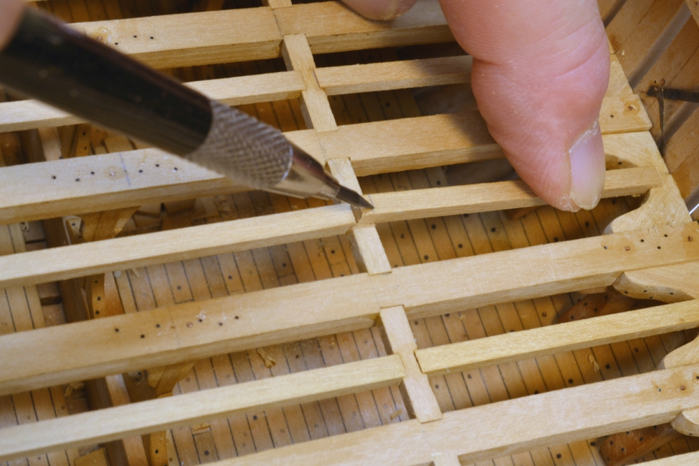
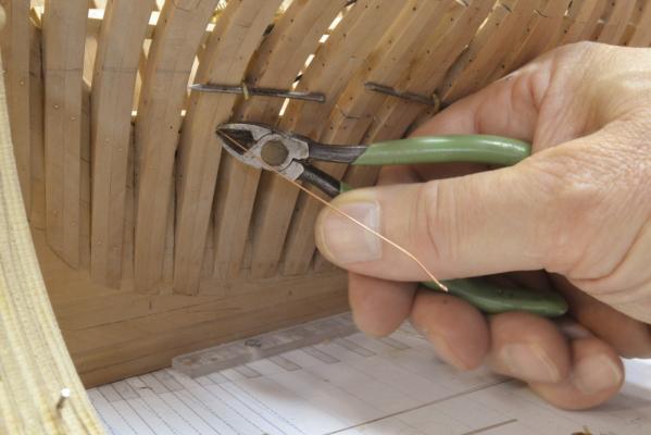
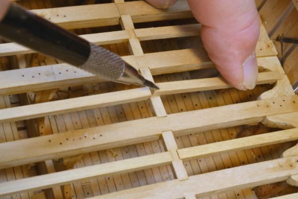
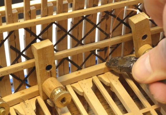
Thank you, Frank. Once the glue has completely dried on the small pieces they can be sawed off close to the frame then filed flush with the frame. Later when the frames are removed, they can be sanded to leave a nice finish. Ed I should add, that the small razor saw shown in the picture cuts on the pull stroke so from the outside the sawing puts little stress on the glue joint - but the joints are plenty strong in any case.
- 3,618 replies
-
- 1
-
-
- young america
- clipper
- (and 1 more)
-
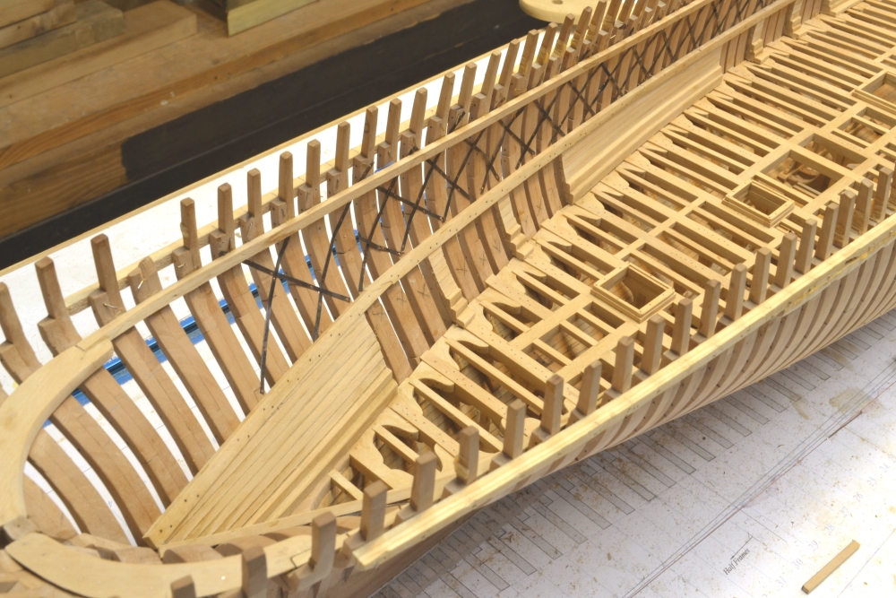
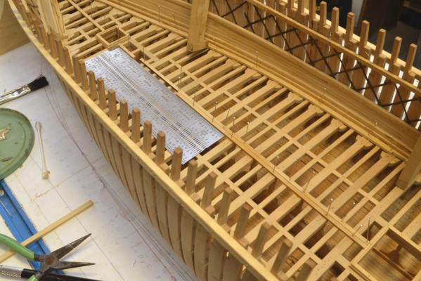
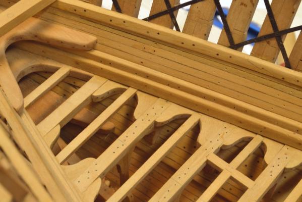
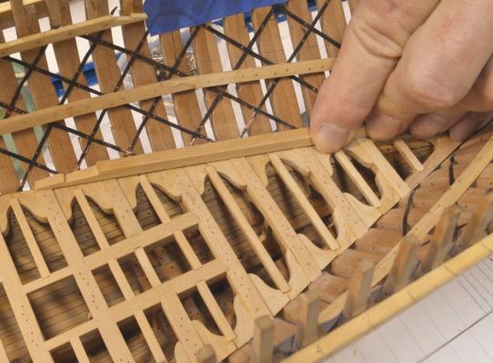
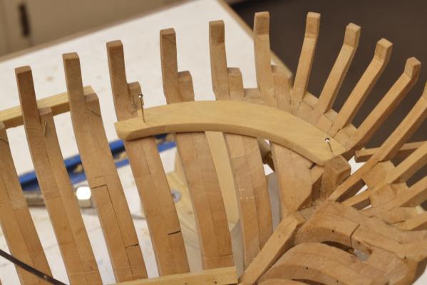
Young America - extreme clipper 1853 Part 72 – Lower Deck continued The lower deck ceiling planking is almost complete. The breadth of the filling planking - and therefore the number of strakes - varies along the length due to the hull shape. The first picture shows an area aft of midship between view ports where a drop plank will be inserted. The planking has been rough sanded only in this picture. Other work has started as the last remaining planks get installed. The two forward hooks have been installed as shown below. The first middle deck beam has been fitted in this picture. The next picture shows the run of ceiling completed on the starboard side. The next picture shows the bolts at the planking butts installed and holes marked for drilling of treenail holes. I will not bother installing treenails where they will be covered by the middle deck hanging knees – every other frame. The next picture shows the short planking pieces over the viewport frames that will be left in place. These small planked areas will allow hanging knees to be installed. The excess lengths of plank on one of these is being trimmed back with a small saw. The exposed frames will later be removed - from the lower futtock heads up to the underside of the middle deck clamps. There will be minimal planking on this deck, but the hatch coamings need to be installed first. the forward hatch parts are being fit up in place in the next picture. After assembly - in place - the coaming will be removed and trimmed. The completed main hatch coaming is shown below. The lower deck coamings were not very high. This one is just 12 “ – 8 ½” above the decking. There is a 3” x 3” rabbet in the head ledges to seat the covering planks. “Iron” bolts have been installed. There is some confusing terminology with these. The term “coaming” refers to both the entire assembly and the fore and aft members themselves. The cross-deck members that clamp down the coaming ends are head ledges. The above-deck corners have been rounded – common practice. Ed

- 3,618 replies
-
- 26
-
-
- young america
- clipper
- (and 1 more)
-
E&T, Fascinating research. Capping off the stack of these chocks with an iron tank - what a delightful model detail - if a bit of a strange design. They must have felt cramped on storage space. Do I assume that he tank was moved into the prop storage space when the prop was in use or was it just replaced over the installed prop? Very nice work on the tank, by the way - in fact, lovely work all around. Thank you for posting your work on this unique and interesting ship. Ed
- 346 replies
-
- 1
-
-
- terror
- polar exploration
- (and 2 more)
-
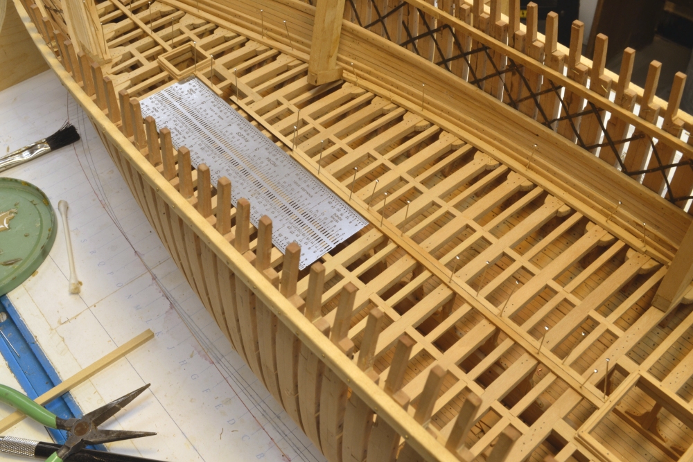
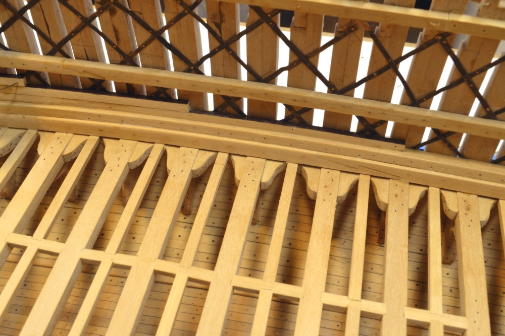
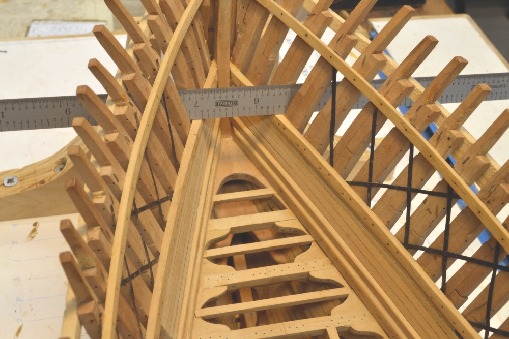
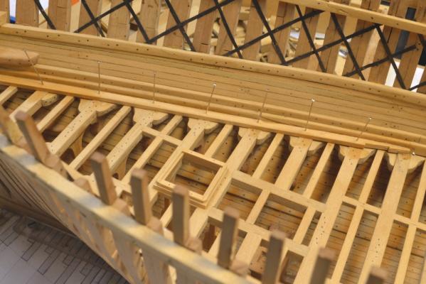
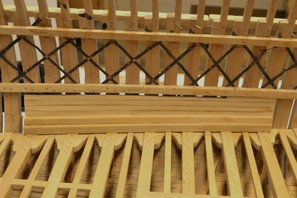
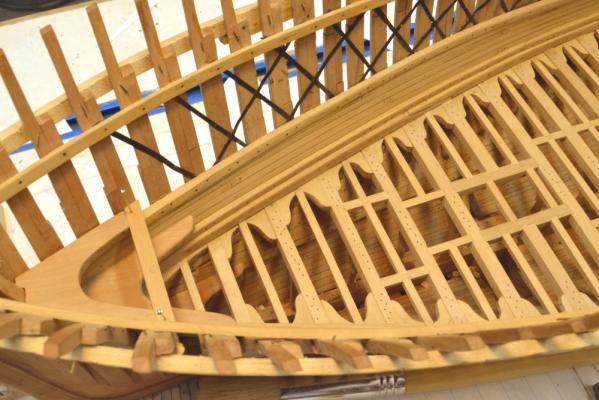
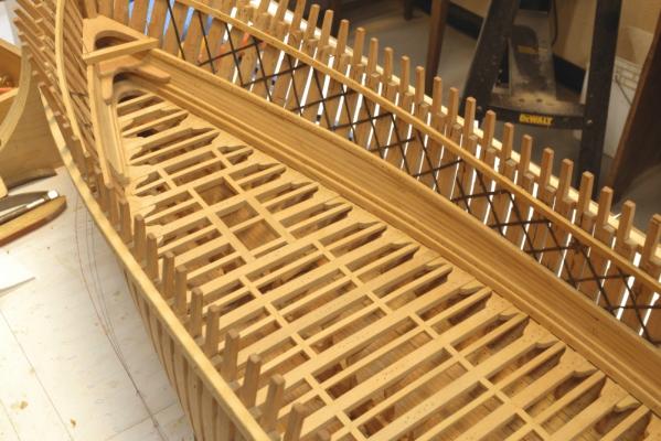
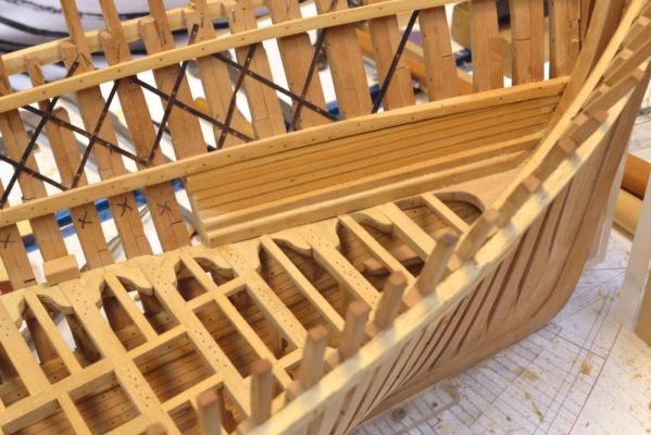
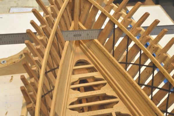
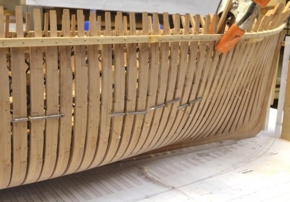
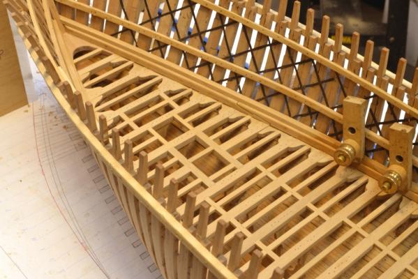
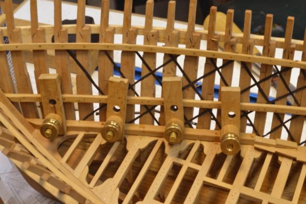
Young America - extreme clipper 1853 Part 71 – Lower Deck Standing/Ceiling Strakes Work continued on the remaining lower deck waterways and standing strakes. Filling planking was also begun at the bow. The first picture shows planking being glued on both sides – with the aid of clamps and wedges. The second picture shows the horizontal bolts – two per frame – through the standing strake and the frames. The standing strake is the thick member atop the waterway. These are monofilament. Through holes were drilled from the inside with a right angle drill. Those through the waterway below are functional copper wire bolts with epoxy as discussed earlier. They have not yeyt been blackened. The next picture shows further progress with the forward planking. All the filling planks on this deck are 6” thick. The picture also shows planking on the port side in progress. The glued plank is held by wedges in this case. The next picture taken at the same time shows the space left open for the view port. The X-marked frames will be cut out later. Small pieces of waterway have been installed on the frames that will be left. these will be planked up so that hanging knees can be installed on the beams at these locations, All the small pieces will be trimmed back to the frame faces as shown at the forward end of the opening. The next picture shows all the planks installed on the forward port side. Fastenings need to be installed on all this planking – bolts for the heavy structural members and treenails for the ordinary ceiling planks. In the next picture the middle deck clamps near the stem have been dubbed off and are being checked with the ruler. This will allow the middle deck hook to be fitted. The will also be a breast hook between the two decks. Ed

- 3,618 replies
-
- 29
-
-
- young america
- clipper
- (and 1 more)
-
Sherry, I would take vents up both sides of each barrel and add vent passages from the ends of the trunnions into those. In looking at a closeup of your casting, it appears you may have some mold alignment problems as well. If you used vaseline in the mold before pouring the resin, that may account for the incomplete filling. These are all common molding problems. Again, I think you may find lo-temp metal to be easier t0 work with. Good luck. Casting is a journey. Ed
-
Sherry, I have never had much success with casting resin on a small scale, but have cast thousands of miniature figures in metal using epoxy molded patterns. You have not shown a picture of your mold, but I assume you have included vent passages from the bottom of the molded part up and out the top. These are essential to get the air out of the mold and allow the resin to get in. You should not need a big hole if the mold is vented. If you have already made the mold and need to add vents, you can cut them with a knife or a carving gouge. Even with vents you may have bubbles especially with resin. If so, try tapping themold after pouring to work the bubbles out. You can do the same when you pour the RTV to make the mold if you are having bubble problems in the mold rubber. I use a vacuum degassing chamber to remove air from the rubber and a centrifigal molding machine to get the mold filled and any air out, but miniature figures have deep and complex undercuts. Obviously you do not want to go that far to cast a few guns. Guns are fairly simple. I would recommend the low-temperature alloy route suggested by hexnut. The weight of the metal helps drive the bubbles out. If you use metal you may want to dust the mold with talc before pouring. This will help with degassing. I assume you are only using the vaseline solution to coat he pattern when making the mold. I would not use it when casting regardless of the material. Hope this is useful. Ed
-
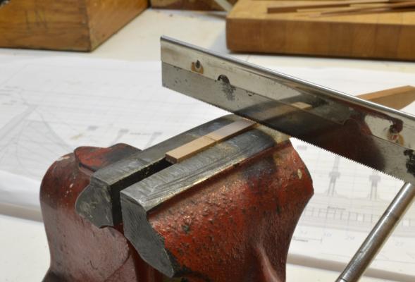
Maury, I wouldn't worry too much about the saw blade. I have been usin this one for at least 20 years. The vise is really just a rough guide. The joints on Naiad's deck beams, with several stepped tables each were much more complex and would be a bear to cut by hand. Also, the large number of identical joints lent itself to a machining set up. A completely different animal. I find these single-stepped scarphs to go much faster by hand. Ed
-
Mark, I believe I bought mine from Small Parts Inc, since taken over by Amazon, I believe. Amazon has some. A much bigger, almost too big, selction is here: http://www1.mscdirect.com/cgi/nnsrhm These people have everything. I believe you can still get there print catalog which is like a set of encyclopedias. Good supplier. Ed
-
The enthusiasm is gratifying, but please don't celebrate too soon. Ed makes decisions like this slowly. Maury, I found this picture showing the saw cuts being made after disking off the face of the scarph. The top of he vise can be used to gauge the depth of the cuts, but after a while you can judge the epth by the number of saw strokes. The depth will get refined after the scrap is pared out in any event. Ed
- 3,618 replies
-
- 10
-
-
- young america
- clipper
- (and 1 more)
-
Hi Maury and thanks. I do not believe I have sequential pictures illustrating the scarph joint method, but if I end up doing a book, pictures and details of the method will be taken and included as with all the other processes. In a nutshell, however, the key tool is a disk sander with the table set 90 deg to the disk. Mark the length of the scarph on the top face - from the end. With the piece on its side, disk off the taper of the scarph from the mark to the end leaving the lip thickness at the end. Saw down into the face at the mark and at the center of the face. Pare and file out the indent for the joining table. Mark the mating joint length from this piece before the first piece is installed if possible, otherwise mark in place. Sand the new face to match - with the disk as before. Then mark, saw and pare out the joining face the same way and trim with a file until it fits. The disk sander assures a flat square face to start with. With practice it goes faster than writing this description. Hope this helps for now. I will see if I have a picture of two. Ed
- 3,618 replies
-
- 6
-
-
- young america
- clipper
- (and 1 more)
-
Nice work on the clamps, Mark. I like the measuring tool and especially the use of the ports to set the deck height. Beautiful craftsmanship as always. Ed
-
Thank you all very much for the comments and "likes". As always, they give me a lot of encouragement. David, I go through a lot of pins. How does onebuild without them? Mauricio, I am afraid it is only me - as I said earlier, about 3 hours a day on average. I do tend to work fast - sometimes too fast. Pete, I have been reading about Webb and of course his endowment of Webb Institute and home for retired shipwrights. A great man and as I understand, a great school. Alan, I do not make bills of materials - too tedious, error prone and not much fun. Several years ago I acquired two slabs of Swiss pear 2" thick and 10 to 12" wide each about 6 feet long and also a slab of Castelo maybe 2" x 8" and of about the same length. I used that plus some real Euro boxwood to build Naiad and expect it to be enough for YA. I cut the wood down to model sizes on an as-needed basis. This is by far the easiest and least expensive way to go even including the cost of the 14" band saw and the Hogg thickness sander. Jeff Hayes did a BOM for Naiad Vol 1 to produce his package and I expect that was quite a task. Bruce, I must agree about the American clippers. I too admire Webb for getting strength without killing off to many forests compared to some others. In looking at the reinforcement by the massive waterways and standing strakes along each deck I realized that having three decks, as opposed to less, also added great strength in addition to offering advantages for certain cargo needs. I never realized McKay's problems with fire except for Challenge, but I would not be surprised if Young America also burned - disappearance without atrace with 1900 barrels of crude oil aboard. Thanks again, everyone. Ed
- 3,618 replies
-
- 3
-
-
- young america
- clipper
- (and 1 more)
-
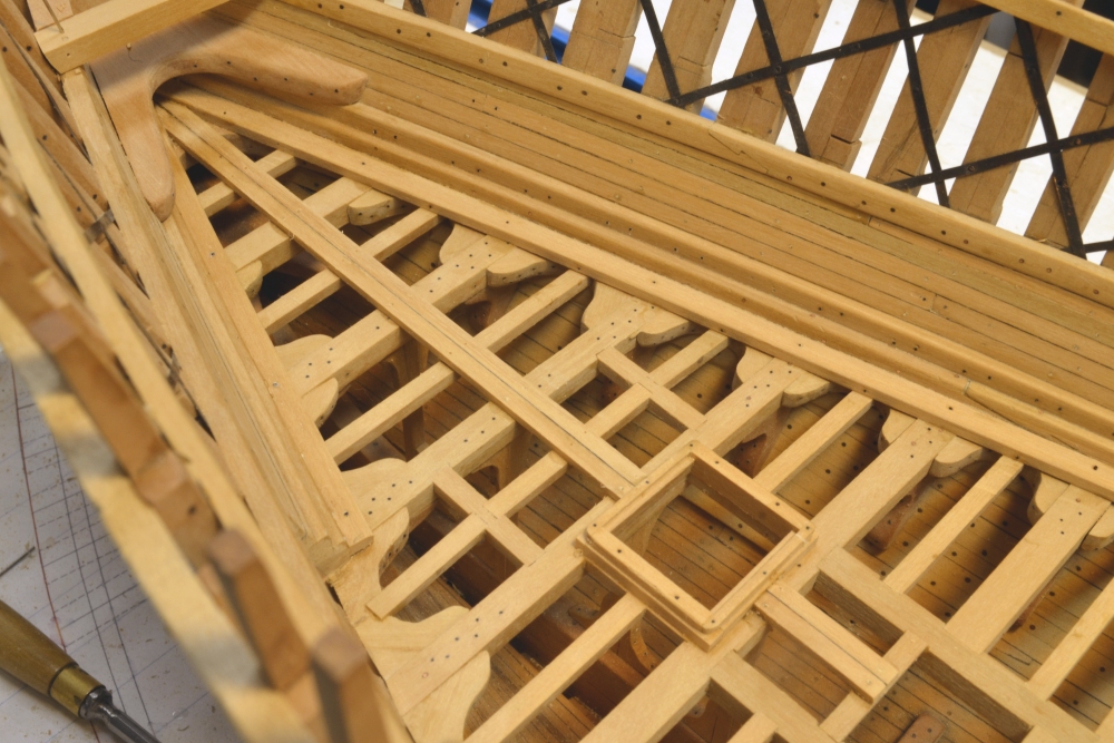
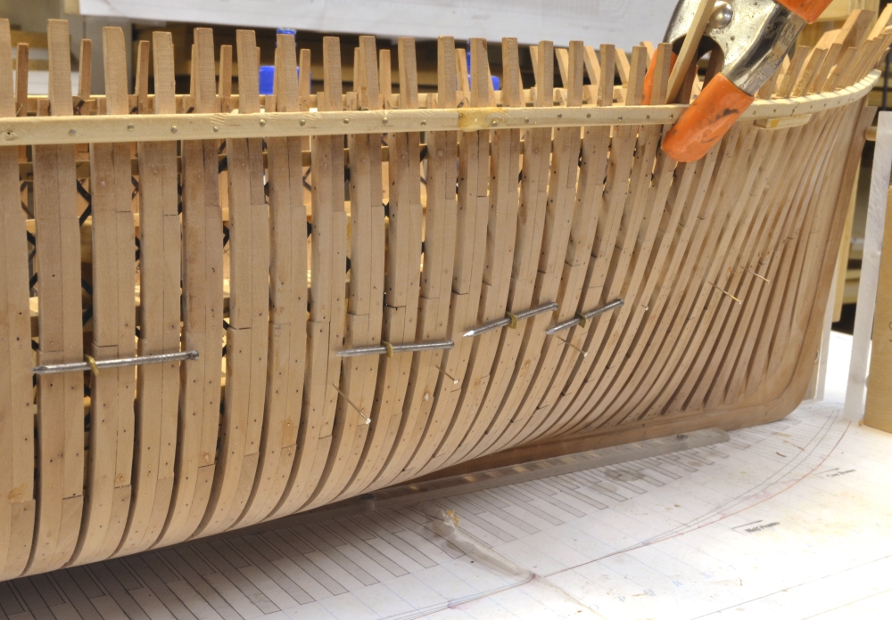
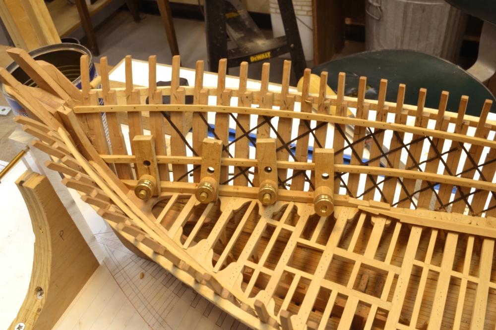
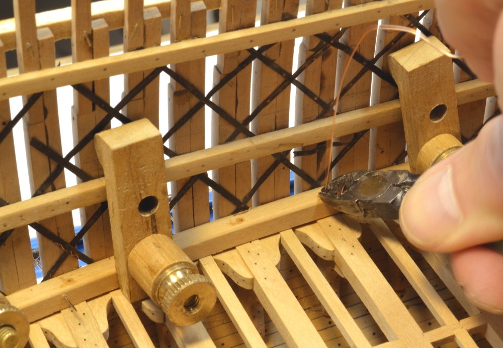
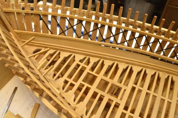
Young America - extreme clipper 1853 Part 70 – Waterways In the last post I mentioned the bolt density on the outside of the frames. This can be seen in the first picture. The nails are part of the clamps being used to secure a section of waterway inside for gluing. The pins are markers for some of the through bolt holes drilled for this section. There will be more – one in each frame pair. The lower deck hanging knee bolts have not yet been installed. These will be dummy bolts only and dummy bolts will only be installed where the frames will be left exposed – lower hull on this side. It was not practical to drill for through knee bolts. All of the bolts for the ironwork lattice have been installed on this side plus of course many others for the members installed earlier. The next picture shows the aft starboard section of waterway being fitted. The outboard face has to be beveled to fit against the frames. The next picture shows a copper wire bolt for this piece being clipped on the outside. I had a bit of rework to do on the main deck clamps aft of midship. For some reason – perhaps I neglected to plumb the hull before marking some of them – their fairness was off on both sides. I saw this on one of those deck-level camera shots. Since they were bolted on, removing them was a chore, but the new clamps are much better. In this picture a batten has been clamped to the side under the deck clamp to help keep the sections aligned at the scarph joints where it is easy to get a kink in the line. Although the main deck does not extend aft of frame 36, I decided to extend the deck clamps right through the cabin, joining it to a half-hook at the stern. The half-hook on the starboard side is shown in the next picture. This hook is interrupted by the sternpost. Its wide breadth is dictated by the bevel required to fit on to the frames. There will be a deck full-width hook for the cabin deck about 4 feet below this – just at the top of the inner post. The cabin deck is a sort of mezzanine between the middle deck and the main deck. The last picture shows the first section of 12” x 10” standing strake installed atop the he forward waterway. The second section is clamped and glued in this picture. This strake has vertical hook scarphs. Ed
- 3,618 replies
-
- 18
-
-
- young america
- clipper
- (and 1 more)
-
Well, lets put it this way, David. Its not going to come apart. Ed
- 3,618 replies
-
- 2
-
-
- young america
- clipper
- (and 1 more)
-
Thanks, everyone. I appreciate the comments and "likes". Karl, I can only humbly return the sentiments you express whenever I look at "Poor Richard." E&T, I too, continue to be amazed at themassive structure - and Webb was not nearly as free with big timbers as McKay! WE have to remeber that these 1850's American clippers were built for the California service and that meant westward passages around Cape Horn fully-loaded - and always at speed, of course. Young America made this passage 50 times in her long career. Not many ships could make that claim. There's more heavy stuff to come. I just ripped off the 10" by 12" standing strakes that cap the lower deck waterways. Druxey, sorry to coin a new phrase - it just popped out. Once you commit to modeling bolts on one of these, you have let yourself in for something. At that, I think I am only getting at half or less than the true number. Its getting crowded on the outside of the frames and I still have most of the dummy bolts for the hanging knees to install. I am starting to experience what the shipyard drillers were faced with - trying to find room for a hole. I have drilled through a few bolts already. There will be two per frame for those standing strakes I just cut. Thanks, again for all the comments and the interest. We have a long way to go. Ed
- 3,618 replies
-
- 5
-
-
- young america
- clipper
- (and 1 more)
-
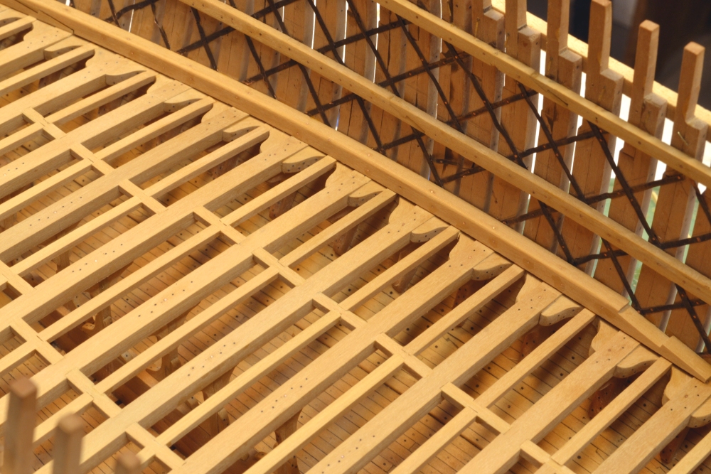
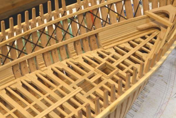
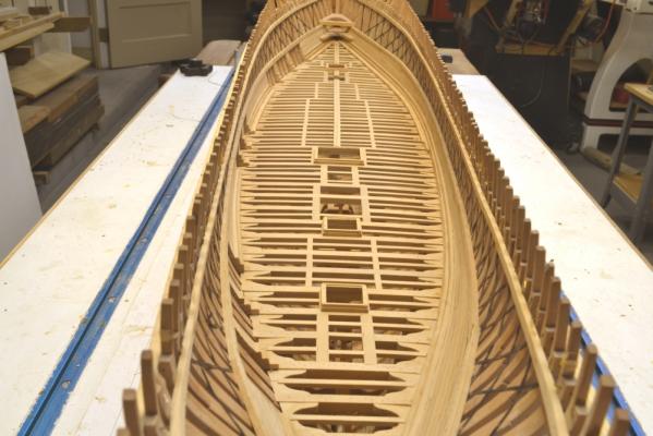
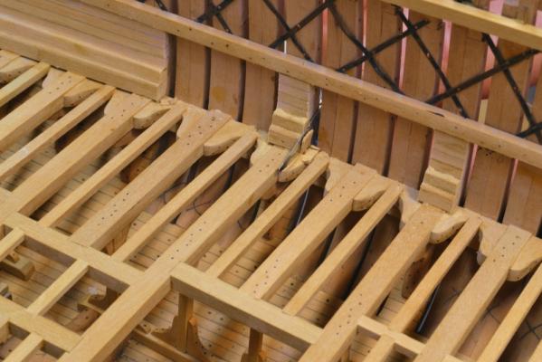
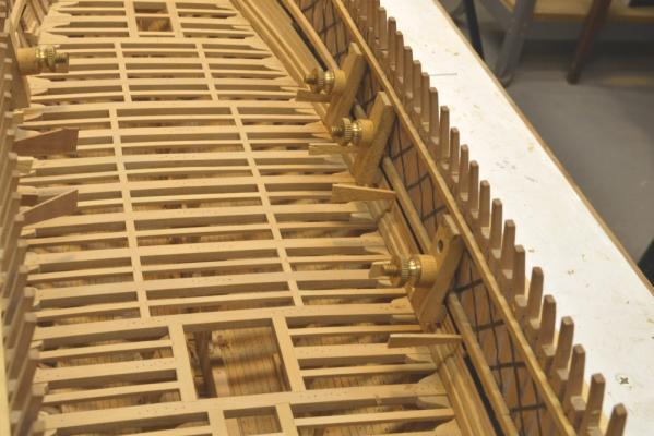
Young America - extreme clipper 1853 Part 69 – Final lower deck framing/ Waterways In the first picture the last ledge of the lower deck framing is being marked for cutting. Once all of the beams and carlings were set, the remaining ledges went quickly – a morning’s work. These are 9” wide and 7” deep – hard pine on the original like the rest of the deck framing – except for the hanging knees – white or live oak. The next picture shows the completed framing – looking aft. Sometimes it is hard to decide from which direction these pictures were taken. The fore and aft ends of this deck are very similar. The next picture shows the area around the main hatch and main mast. At this stage the deck members – beams, carlings, ledges – have been sanded flat and finish sanded. All traces of the bolt glue are gone. Below is a picture taken above the foremast area. No time to celebrate - on to the waterways. These monsters are 15” square – hard pine on the original – as long a log as possible. The first picture shows the foremost section on the starboard side. The outboard face has to be beveled back to fit tight against the frames and flat on the deck beams. There is a slight gap between the waterway and the tops of the lodging kneses. This was discussed earlier. The next picture shows a closer view.. In this picture the section has been glued in and clamped. As many copper wire bolts as the interference with the clamps would allow were then inserted and epoxy-glued from both ends. When the clamps are removed the remaining bolts will be installed down into the beams and through the frames. The hook scarph connecting this piece to the next section was fit before installing the forward piece. I wish I had made this piece longer to get the joint into a straighter area. It was hard to close on the curve. The next picture shows a wire beam bolt being inserted in the next section. The pin coming through in the lower left corner is a marker for the hole drilled from the outside so I can find it to fill it with a bolt. The outsides of the frames are becoming “bolt-dense.” The air gaps above the lodging knees between the beams and ledges show clearly in this picture. The last picture shows the second section of waterway after filing off the bolt heads and epoxy. The waterway has been sanded smooth. A 12” wide by 10” deep “standing strake” will be installed along the top of the waterway. A thick “binding strake” – the outer strake of planking will butt against the side of the waterway and bolted horizontally through it as well as into the deck beams. I believe a “margin plank” was installed inboard of the binding strake, but I am still researching this. Ed


- 3,618 replies
-
- 34
-
-
- young america
- clipper
- (and 1 more)
-
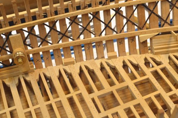
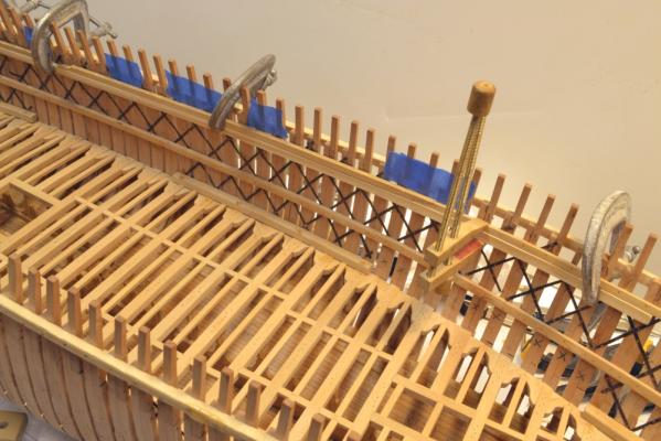
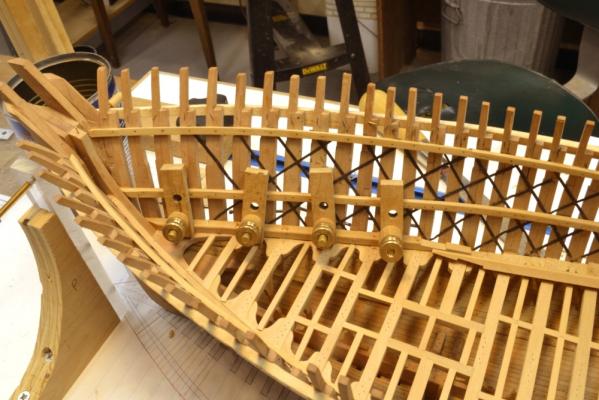
Jan, thank you for your interest and for your question. The blue masking tape is to protect the ends of the iron strapping strips until they get covered with planking or other members. The deck clamps above the middle deck have not yet been extended to the stern because I have not yet decided how to handle the main deck clamp in that area. The main deck ends at frame 36 where the poop deck begins. Below the poop is a cabin deck set below the main deck by a few feet, so no deck clamp is required for the main deck aft of 36. I will probably install it any way for structural integrity but have not yet added that arrangement to the drawings. I should probably add the aft deck clamps soon. The unsupported stern timbers are vulnerable to damage at this stage. Ed
-
Druxey, also in your defence, I too use pliers to change blades and do not really feel threatened by it.
- 3,618 replies
-
- 1
-
-
- young america
- clipper
- (and 1 more)
-
Druxey, it looks like you stirred up a hornet's nest of razor blade afficionados.