HOLIDAY DONATION DRIVE - SUPPORT MSW - DO YOUR PART TO KEEP THIS GREAT FORUM GOING! (Only 13 donations so far - C'mon guys!)
×


EdT
-
Posts
2,213 -
Joined
-
Last visited
Content Type
Profiles
Forums
Gallery
Events
Everything posted by EdT
-
Thank you all. David, you highly overrate my patience. Druxey, I am no snob when it comes to tools. I cherish my lowly razor blades - 100 for a dollar. Besides, after shaving (sorry for that) off a dozen monofilament bolts, the edge is completely gummed up with CA glue from one end to the other - so, at the going price, I can either toss it and peel open a new one, or drop it into a jar of acetone for a bath and pull out a clean one - all without dismantling a surgical blade holder - always a dangerous proposition for me. Ed
- 3,618 replies
-
- 4
-

-
- young america
- clipper
- (and 1 more)
-
Gaetan, there is only one person who can truly judge your work and that is you. For my money, your work is magnificent. Ed
- 728 replies
-
- 7
-
-
- le fleuron
- 64 gun
- (and 1 more)
-
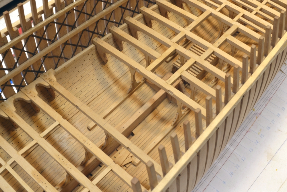
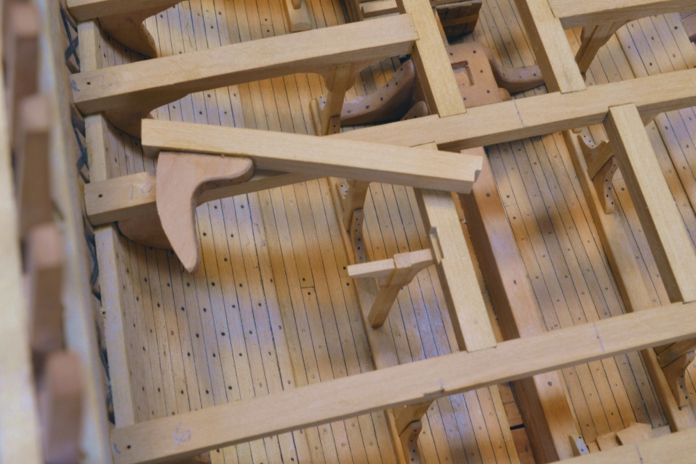
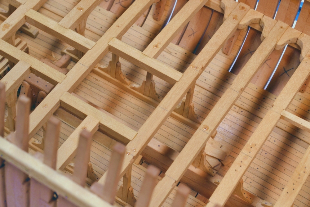
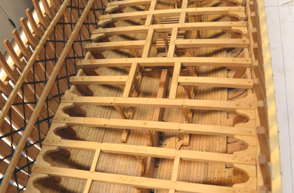
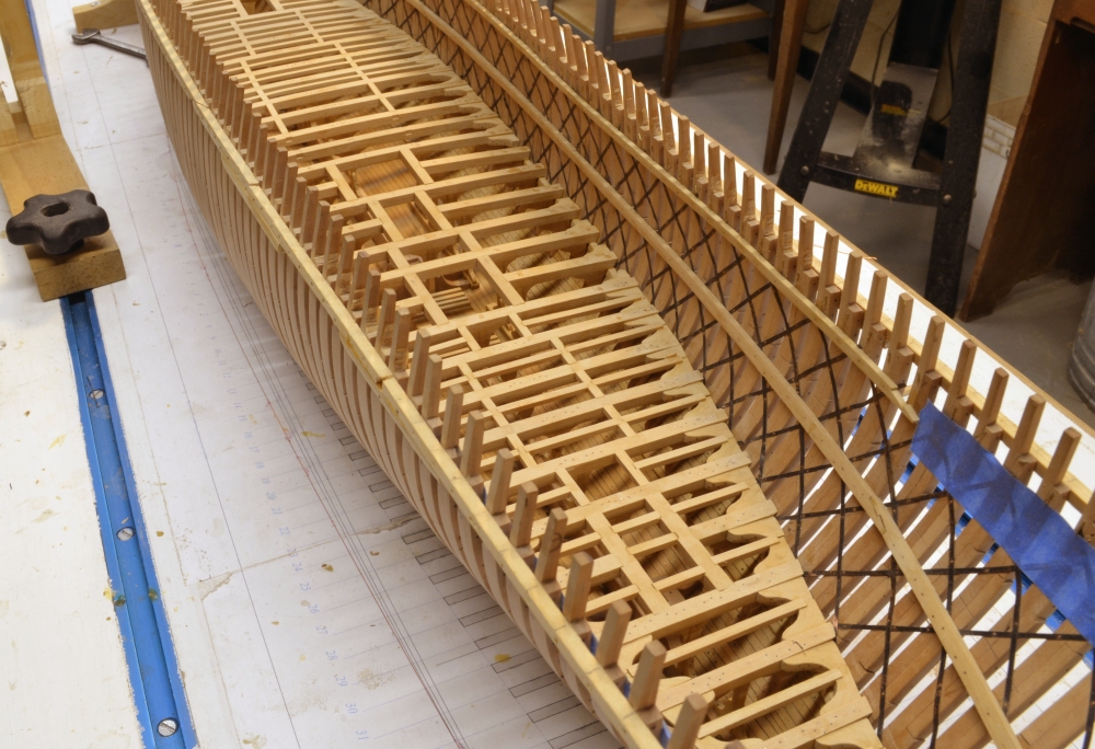
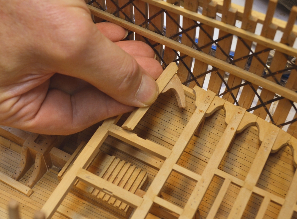
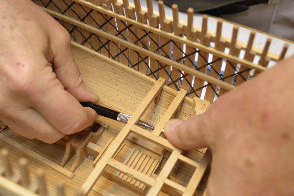
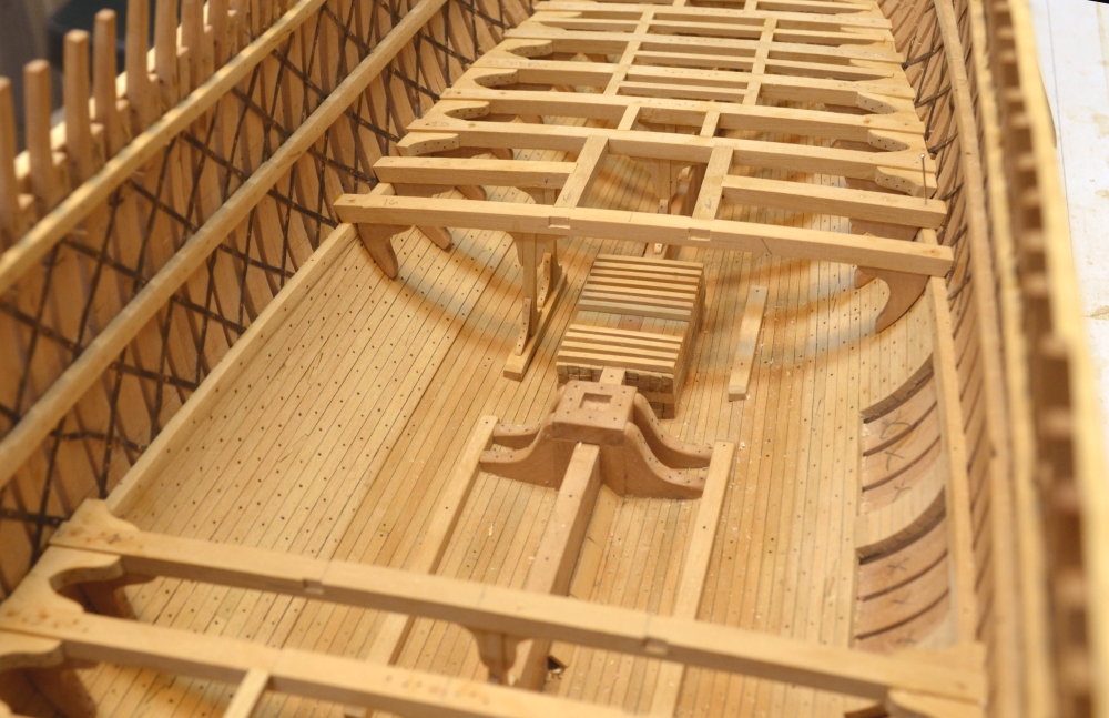
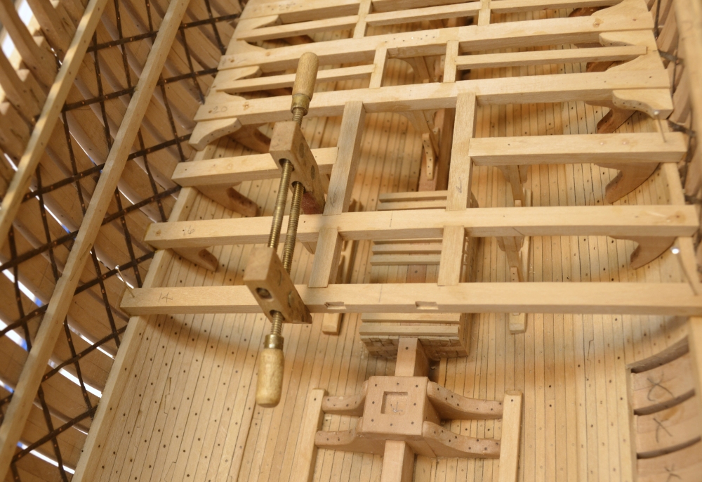
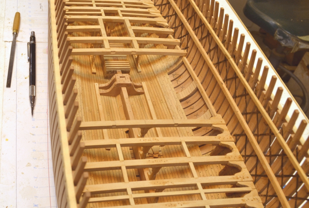
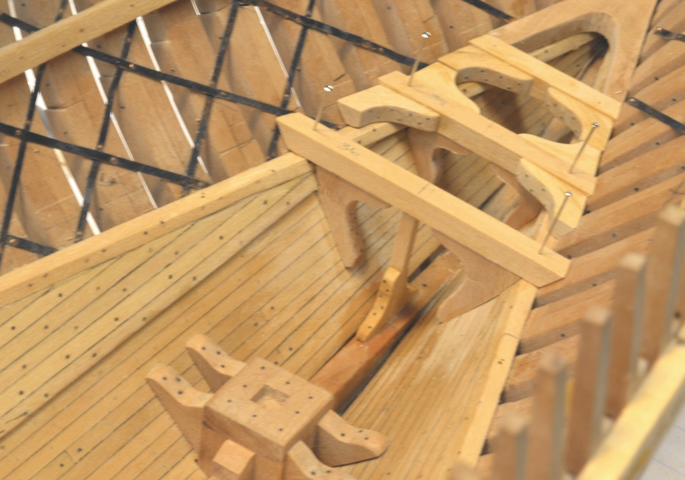
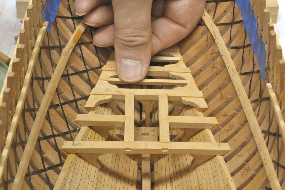
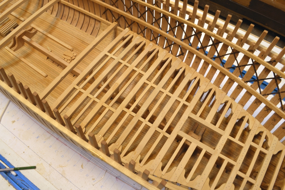
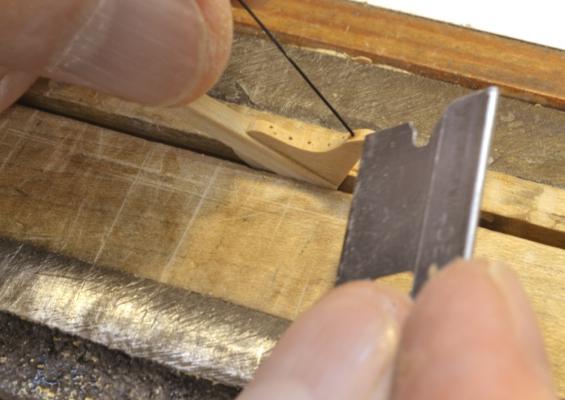
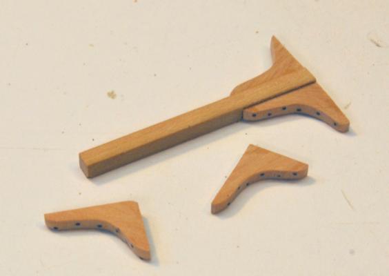
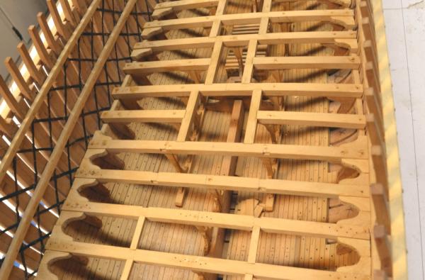
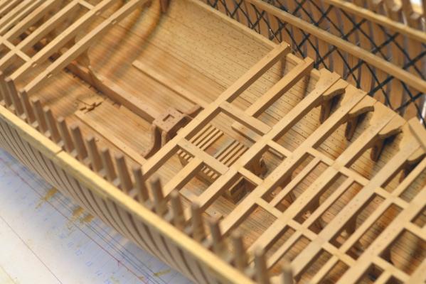
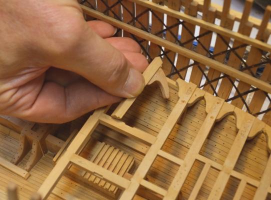
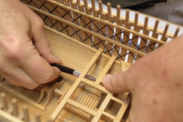
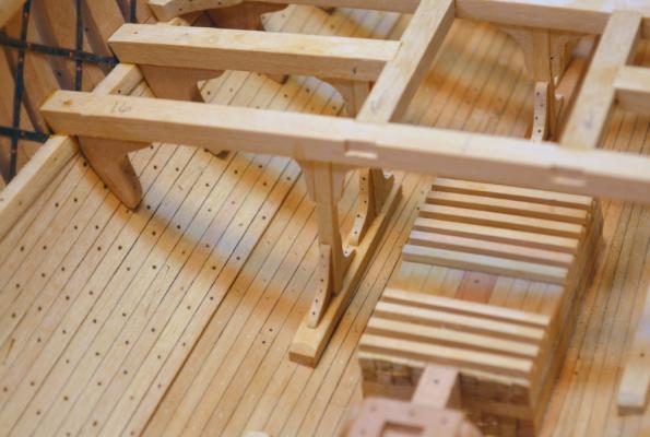
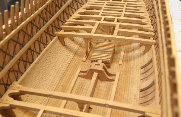
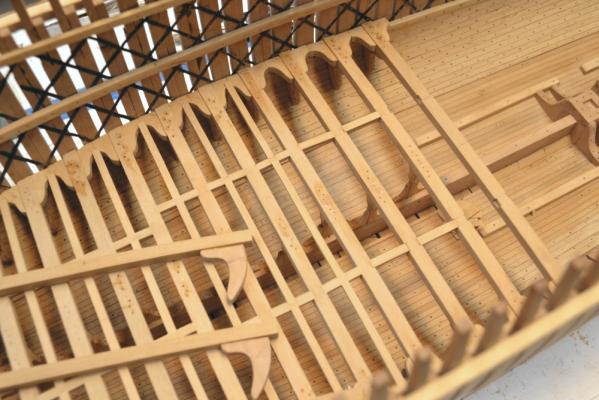
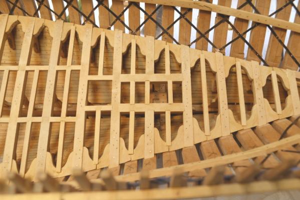
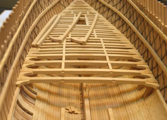
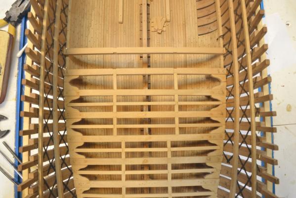
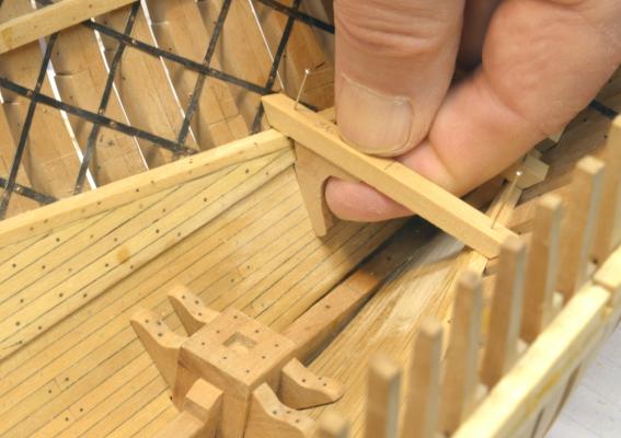
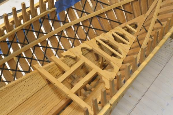
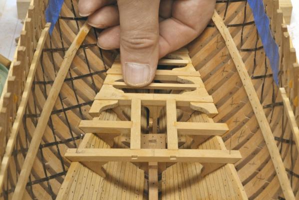
Young America - extreme clipper 1853 Part 68 – Lower deck framing continued In the first picture the beams around the opening for the main mast have been installed. The forward beams and half-beams around this opening have double pillars – one on each side - set on the base timbers on the hold planking. Making and setting these pillars, with their four knees each, is a large portion of the work involved with these beams. The next picture shows a monofilament bolt being installed in an upper knee that has already been glued into an assembly. The next picture shows the three parts of a pillar assembly ready for installation. The lower knees will be installed after the top assembly is set in place and glued. In the next picture the final beam – a half beam – is ready to be installed. Unlike the other pillars, this one has been pre-installed since there will be insufficient space to do it later. The hanging knee has also been pre-attached to the half beam for this reason. The pillar is pinned to the base with a piece of wire. The next picture shows the final beams installed. Copper wire bolts have been installed through the tops of the beams to help secure the them, their hanging knees and each of the pillars these are glued with epoxy that has not yet been sanded off the tops of the beams. The next picture is another view of this area. All of the work below the beams has been finished with beeswax solution before installing the ledges. Missing lodging knees, carlings, ledges and a lot of monofilament bolts still need to be installed to complete the lower deck framing. The last picture shows most of the lower deck at this stage. Ed


- 3,618 replies
-
- 34
-
-
- young america
- clipper
- (and 1 more)
-
My congratulations on the award as well, Gaetan. Well deserved. Ed
- 728 replies
-
- 2
-
-
- le fleuron
- 64 gun
- (and 1 more)
-
ancre LE BONHOMME RICHARD by Jeronimo - FINISHED
EdT replied to Jeronimo's topic in - Build logs for subjects built 1751 - 1800
Magnificent work, Karl. Bravo! Apart from the extraordinary modeling work, I especially like the color you have achieved with the wood finish. Ed- 662 replies
-
- 1
-
-
- bonhomme richard
- frigate
- (and 1 more)
-
Please don't apologize, Alan there is a lot of stuff to look at on this site. I am happy to get the question, especially on this - one of my pet subjects. Ed
- 3,618 replies
-
- 2
-
-
- young america
- clipper
- (and 1 more)
-
Alan, thanks again for your comments. The pin-indexing method is a major improvement over the assembly jig for the following reasons: the alignment of the individual parts of the frame is very accurate assembly is much faster final frame is very accurate in shape assembled frame has patterns left on both sides allowing almost complete beveling before erection no clamps are needed cross-spales - if needed - can be attached and center-marked while the frame is still accurately pinned to the pattern final alignment/fairness of frames on the assembled hull was more accurate - almost no fairing required. with only one assembly clamping jig, it becomes a bottleneck - its easy to cut multiple pin boards However, there are some additional requirements: a pattern is required for both faces of the frame (also with the jig method) matched indexing holes are required on the patterns pin holes must be drilled perpendicular and on the marks If the pinholes are placed on the pattern using CAD - in other words precisely aligned - then the only source of error in the process is the placement/verticality of the drilled holes in the parts. A drill press and some care eliminate most of this. Preparation for this approach begins with the frame lofting. It is an integral part of the entire process. Pin holes have to be placed on each pattern of the assembled frame half with the frame patterns aligned. I believe this could be done manually on printed frame patterns of assembled frames but may not be as accurate. I have not tried this. It could not be done if there are only patterns of the parts. If there were spacers between the frame partners and/or if the sidings were reduced before assembly I believe this would still work, but have not tried it. I believe if you check back through the earlier posts you will find some more explanation of this. Ed
- 3,618 replies
-
- 4
-
-
- young america
- clipper
- (and 1 more)
-
Hi Guy, I assume you are referring to the tops of the beams being slightly higher than the tops of the lodging knees. If so, step back to the previous page. Mark had the same question. Short answer - yes. Ed
-
Thanks for the input, Bob. I actually do what you describe in your first paragraph - using the 10 second setting - and I do use the interval to get set up if my hands, for example, will be in the picture, which is the case in many photos. The shutter release on the remote - the part of it attached to the camera - has a more sensitive button that works exactly like the release button on the camera - partial depress to focus, etc. so I use that button rather than the remote itself. I did not know that the mirror could be locked out of the way after composing the shot until you mentioned it, though I am familiar with the SLR mechanics. As you say, so far I have not seemed to need that feature and it would add another step. I could see where the mirror flipping could induce some bounce if the setup is not very rigid - and some of mine are not, so I will keep an eye out for that problem. I am normally shooting at around f16 with an ISO setting of 400 and that seems to work out well. Thanks, Ed
-
Bob, that is a remote shutter release and the camera is a DSLR - a Nikon D3100. It has mirror lock-up but seems to be used only for cleaning. I have not used it. I normally use the release timer. Is that what you meant by delayed release? There does not seem to be any other delay feature. Ed
-
Gaetan, all you need now is a few model-building robots. Amazing array of gadgets. Ed
-
ancre Le Fleuron by cabrapente - FINISHED
EdT replied to cabrapente's topic in - Build logs for subjects built 1501 - 1750
Great work. Wonderful detail. Looks like you are ready to start rigging. Ed- 332 replies
-
- 1
-
-
- le fleuron
- 64 gun
- (and 1 more)
-
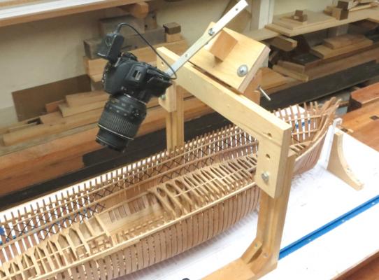
Young America - extreme clipper 1853 Part 67 – Lower deck framing continued I had my small camera in the shop so I took this first picture with it. It shows one of my more important tools. No one would design this contraption this way from scratch. It was first just a simple fixture to allow me to take overhead sequential shots during Naiad’s magazine construction. It has since evolved into the adjustable mount shown below. You can get seasick looking at some of the pictures taken with this but they can easily be rotated in post processing. I take very many pictures including lots of in-hull close-ups and could not do without this thing. I take all the photos in available light using aperture priority so the camera is stopped down to increase depth of field. Thus, the shutter speeds are quite slow requiring a mount. Most of the pictures are still taken using an almost-normal tripod. Pardon the digression, but I thought it might be of interest, since we cannot build ships any more without photography. Back to the work. In the next picture the beams are progressing forward. The large opening is for the larger of the two rectangular, vertical fresh water tanks. The half-beams and headers are pinned in place at this point. The next picture shows a hanging knee glued to one of the half-beams. This knee was fit before the knee on the beam forward was in the way, but it will be glued in after that beam is installed. The difficulty in holding these knees under the beams for fitting dictates some preplanning. In the next picture all is installed on the starboard side and a pillar assembly is being marked for sizing under the beam. In the next picture both pillars with their knees have been installed on the starboard side. Next is a picture of the same area from further back. In the next picture the beam forward of the smaller water tank has been glued in and the headers on either side are being installed with the help of a clamp.. The pillars on the port side have also been installed in this picture. These last three beams all require lodging knees and ledges. The last picture shows the current status of the framing. Two full beams and two pair of half-beams remain to be installed to fill the void. Ed


- 3,618 replies
-
- 30
-
-
- young america
- clipper
- (and 1 more)
-
Again, thanks for the comments, "likes" and especially the superlatives - even though overly generous. Mark, the short answer to your question is yes - the space would help thwart rot in this very rot-prone area. The sectional views of typical construction in my prime source on American clippers (Crothers) shows the top surface of the lodging knees below the tops of the beams on all decks. The lodging knees sidings are typically a couple of inches less than the depth of the beams in most of the documented scantling lists. On the lower deck, my beams are 14" deep and the lodging knees sided 12". Considering snaping of the beam ends ,and say, 1" scores in the clamps, this does not leave a lot of room for space if the tops of the lodging knees are parallel with the beam. However, I did not score the beams, at least on this lower deck where the detail is invisible. I snaped the beams just enough to get them to rest nicely on the dubbed off clamps. With the knees set hard down on the clamps, I probably have about 1" or more of space between the tops of the lodging knees and the tops of the beams on this deck. This was set by eye when gluing in the knees. They may have actually been bolted down into the clamps - I don't know. Now, at the risk of opening up a can of worms, I think space may have been deliberately left on 18thC RN ships as well. I don't know. Some expert comment is welcomed (Gary? Druxey?). Lodging knees on these ships were normaly a few inches (4" on a 74?) less in siding than the beam depths, meaning there had to be some space left between the knee and the clamp or between the knee and the top of the beam. Virtually every cross-section in Steel's plates shows the top of the knee horizontal and therefore departing from the rounded up beam top toward midship - leaving a space. On my Naiad, the the tops of the lodging knees at the ends of the arms are about an inch lower than the the top of the beam at that point. The differences in sizes were less - for example on the lower deck the beams are 10" deep and the lodging knees sided 8". With the beam snaping and the clamp scores the tops are virtually flush at the side - but perhaps an inch lower at the inboard ends. All this is highly academic to be sure. It cannot even be seen on the Naiad's lower decks, and I can barely discern it on the higher decks. Ed
-
Great work, Toni. Its always a dilemma deciding what to leave off for visibility. Ed
-
Thank you, Alan. The ship itself is what I find stunning - the size, the massive timbers, the structural symmetry, the sleek lines.... I could go on. Its a challenge doing her justice. I'm afraid that chemical plants are not too stunning unless you have a thing for complexity and acres of steelwork, pipes, distillation columns etc. However, as projects they are like having the world's largest erector (aka mechano, aka lego, aka tinker toy) set to play with for a few years - with lots of helpers.. I would say that I average maybe 3 hours per day on the model - some days not at all, somedays more. This excludes drawings and research. Retirement helps. Thanks for your interest in the build. Ed
- 3,618 replies
-
- 4
-
-
- young america
- clipper
- (and 1 more)
-
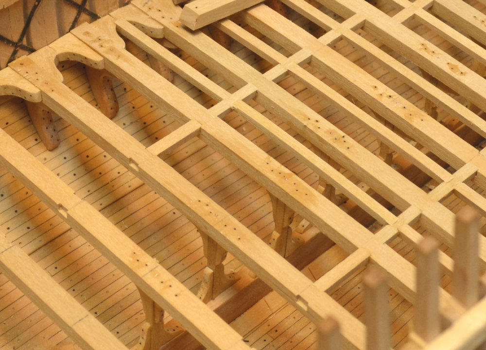
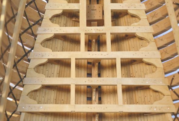
Young America - extreme clipper 1853 Part 66 – Lower deck framing continued For those not yet exhausted by pictures of the inching along of the lower deck framing, here are some photos showing the latest progress. In the first picture bolts have been installed in the tops of most of the forward beams. The bolts represent fastenings for the hanging knees and the knees at the tops of the pillars. There is also a bolt down through the beam into each pillar itself. The next picture is a closer view of the bolts. The glue – epoxy or CA – has not yet been sanded off in this picture. The next picture shows bolting on the beams just ahead of the mizzenmast. In this picture most of the glue has been sanded off. The black bolts are dummies of black monofilament glued in with CA. The shiny copper wire bolts are functional. That is, they are epoxied through the beam into the members below and are lending strength to the glue joints of the hanging knees, the pillars and the beams themselves to the clamps. The top of the framing will get a final leveling and final sanding after the ledges are installed. The next picture is another view of this area. The next picture shows the framing forward of the mainmast. Carlings have been installed back to the last beam with a pillar installed. All of the lodging knees have been installed. Hanging knees have been fitted to the two beams lying on the deck. They will be the last to be installed. At that point there will be no room for fitting the knees under the installed beams. In the next picture almost all of the ledges have been installed in the aft section. Note the irregular pattern of central ledges over the mizzenmast step. Apparently these ships had supporting partners only at the main deck, so the mast opening is just framed on this deck. The last picture shows another view of the forward framing. The remaining framework gets more interesting. There are a lot of half-beams and double pillars astride the main mast, main hatch and the water tanks. Ed


- 3,618 replies
-
- 32
-
-
- young america
- clipper
- (and 1 more)
-
Thnks for these comments - always most welcome. Druxey: I appreciate your vote of confidence - means a lot to me. Exposing faults - and there are many - to the world can be intimidating. Also, I do not often see them myself until they show up in the photo - especially when it is one of those frightening closeups. Dave: Thanks for taking the tme to go through the log and for your comments. I have seen your work. You are being way too modest. Ed
- 3,618 replies
-
- 1
-
-
- young america
- clipper
- (and 1 more)
-
Thank you all for these comments, for all the "likes" and for your support in general. This is of immense help to me in keeping focused on the project - especially during the long periods of repetitive work - like now. When I am about to install a piece that isn't quite right, I find myself thinking, "What is that going to look like on the blog?" Ed
- 3,618 replies
-
- 8
-
-
- young america
- clipper
- (and 1 more)
-
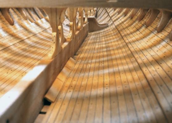
Since that last view was popular, I will have to take some more. Without the use of mirrors or other micro devices this has to be done while the camera will still fit down in he hull. The picture was taken with a 2 1/2" x 4" Canon Powershot set down onthe keelson. The photo was then cropped. The Powershot is not the smallest of cameras, but it is a lot smaller than the slr I use for most of the pictures. The light from above plays tricks with the colors. I could have done a better job with the post-processing. The picture is a bit light. Here is a better version. Ed
- 3,618 replies
-
- 31
-
-
- young america
- clipper
- (and 1 more)
-
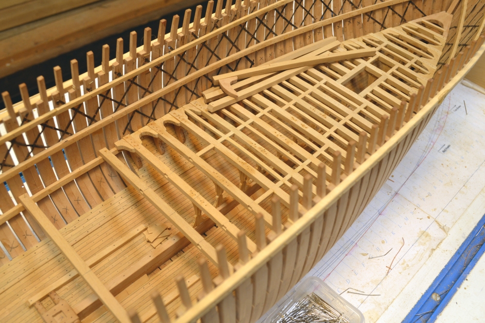
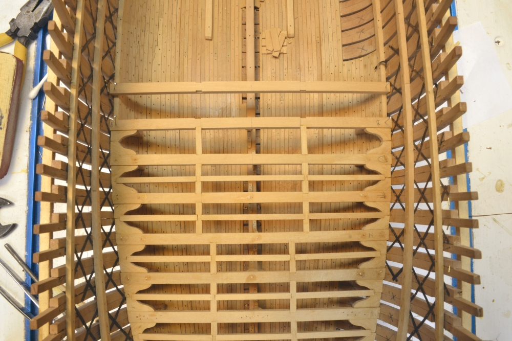
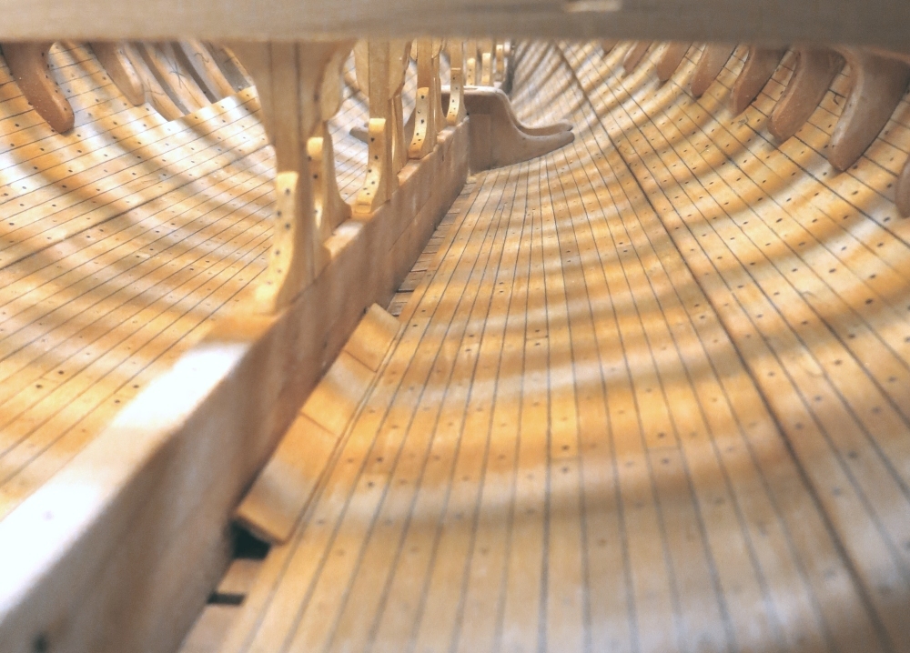
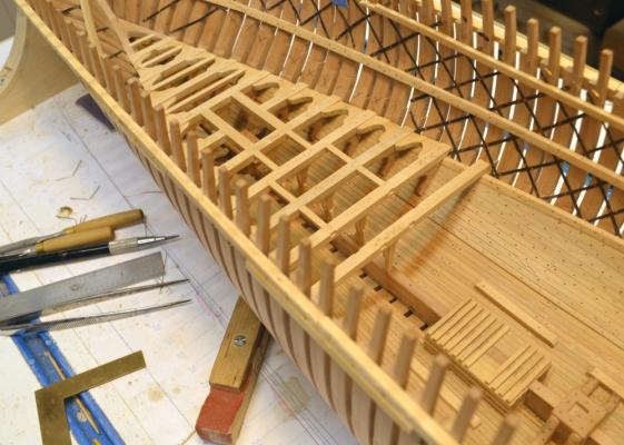
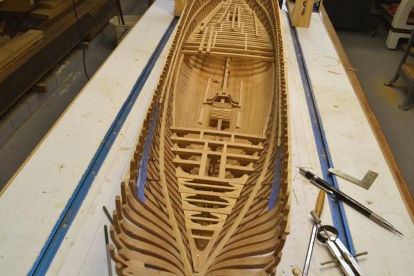
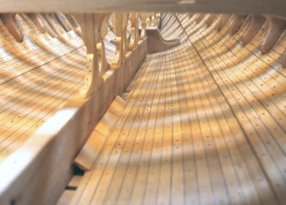
Young America - extreme clipper 1853 Part 65 – Lower deck framing continued More of the same, I’m afraid. It looks like the lower deck framing is going to take about a month. The first picture, taken from directly overhead, shows the lower deck framing back as far as the midship beam. Once the last beam forward of the midship view port is installed, I intend to work from the stern forward so the last frames will be those at the view port. Having only one hanging knee to fit on these beams will reduce the fitting of these in the last tights spaces – and also to allow plenty of room for fitting the aftermost small beams by doing those first. In the next picture a hanging knee is being fit to one of the small beams at the stern. The limited space is apparent. This knee was cut using the new pattern shown in the last post. In the next picture the installation of that beam has been completed – except for the lodging knees The next picture shows the aft framing progressed past the mizzenmast step. A ledge is being glued in the next picture. The next picture shows the extent of the lower deck framing currently completed. I need to get going on some of those lodging knees. This picture gives a good idea of how for forward the "deadflat" midship frame is placed. Finally, a look forward below deck along the keelson. The height of that keelson is 4 feet above the floor frames. Ed

- 3,618 replies
-
- 34
-
-
- young america
- clipper
- (and 1 more)
-
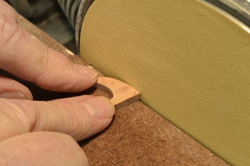
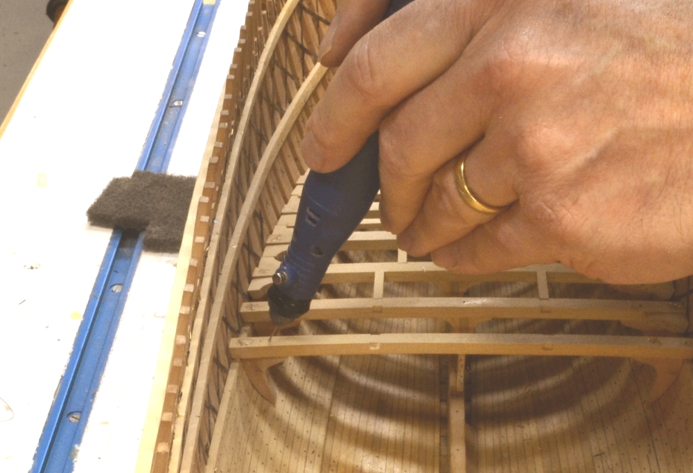
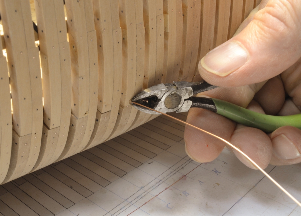
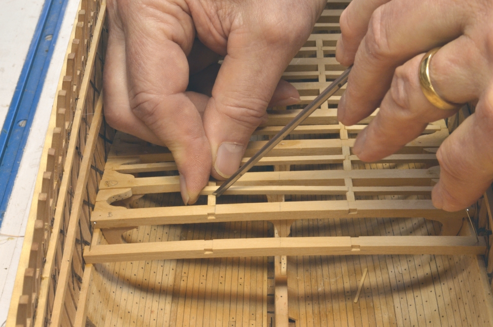
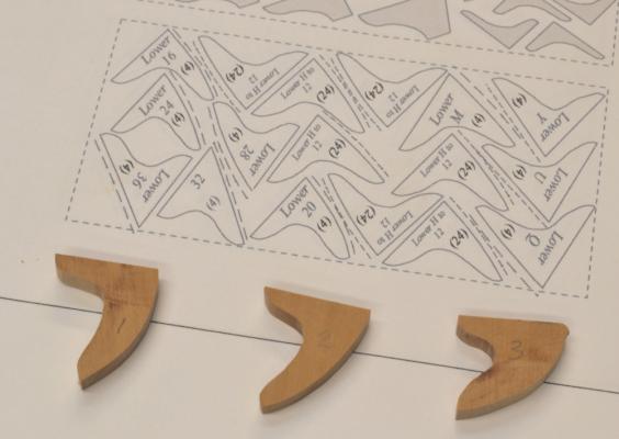
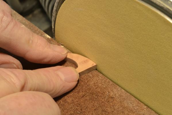
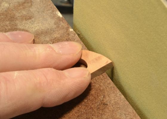
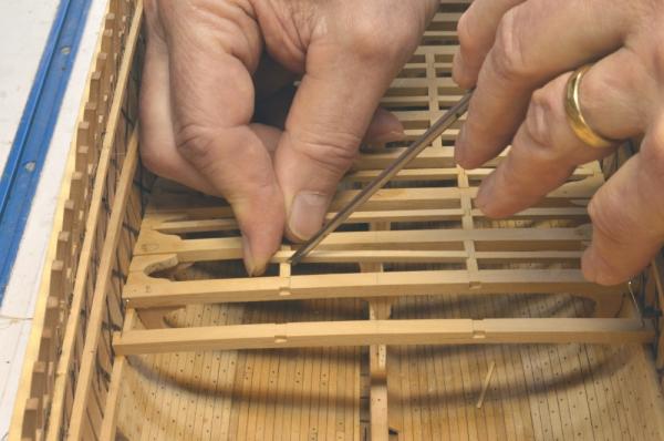
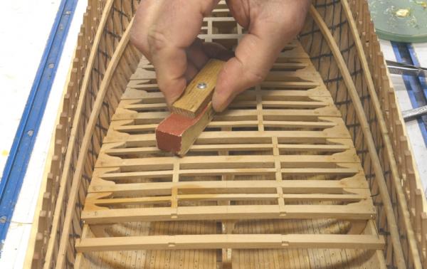
Young America - extreme clipper 1853 Part 64 – Lower deck framing continued There are not a lot of new kinds of work going on at present – just a continuation of the lower deck framing – very repetitive. Item for item, the hanging knees absorb much more time than any of the other deck framing components. I mentioned earlier that I am using a few “starter” shapes that are then modified to fit a given location. The first picture shows the three shapes initially used on the lower deck. The center and left shapes - to be used in the central part of the hull - worked out fairly well. The shape to the right was a guess that I took at a starting point for the knees at the ends – not as good a fit. I eventually surrendered and lofted the more complete set of 11 different starter patterns shown at the top of the picture. The differences between those at the ends and the single piece at the right are pronounced, so this additional lofting for the other decks is planned. The pattern shapes are marked with frame numbers and the number required of each in parentheses. Each pattern will yield 6 frames when cut from a 1” thick block of wood. The new shapes are still only approximate and will require shaping to fit. The next two pictures illustrate my process for this. First a knee is held up under the beam and the high points noted. These are then sanded down using the disk sander as shown above. This is repeated until there is a match. The knee is then beveled as shown in the next picture using the tilt table on the sander to help with uniformity. After fitting, the knee can receive its dummy bolts, get a final sanding and be glued in place. To strengthen the connection, two copper wire functional bolts are installed after the glue sets. The next picture shows a hole for one of these being drilled down through the beam into the knee. The hole is drilled at an angle into the throat of the knee to resist it coming loose. A copper wire is then coated with epoxy and pushed into the bottom of the hole. Another bolt is then installed from outside the hull as shown below. The epoxied bolt is being clipped off in this picture. The hole for this bolt is also drilled into the throat of the knee. Additional dummy bolts will later be added to the outside of the frames and to the top of the beam. All will be black. The carlings and ledges are being added in the wake of the beam setting. The score for a ledge is being marked in the next picture. The ledges are centered on the carlings by eye and the top corners of the carling marked with the chisel. This is much more accurate than pencil marking. The seat is then filed out. All the ledges are cut from straight pieces. I did not round up the ledges on this deck. Ledges set in the center are fixed slightly higher than the tops of the carlings, and then rounded off to match the beams by sanding as shown below. The framing will not be finish-sanded until all bolts in the tops of the beams are installed. The last picture shows the current state of the framing. Wax finish is being applied progressively to the areas under the installed beams. The last beam set in this picture is at the dead flat. This terminology is something of a misnomer in that, unlike the configuration of most earlier ships, it is not at the widest point in the hull except in the neighborhood of the load waterline. Above that height the breadth is slightly greater in the next frames aft and the maximum breadth in the lower hull occurs in the frames slightly forward. The differences are small but it is an interesting point – probably the result of the original design being developed on a half-model and the offsets for construction taken from that – the nicety of a single dead flat frame being lost in the process. This midship frame also occurs at about 25 feet forward of the midpoint of the hull – so I am not yet at the halfway point in framing this deck. Ed


- 3,618 replies
-
- 24
-
-
- young america
- clipper
- (and 1 more)
-
Lovely work, Pete. Could you describe the process you used for the ship's name lettering. Ed
-
Thanks, everyone for the comments and "likes." I am always overwhelmed by these. Hello, Allan. I have not seen these hanging knees referred to as standards in any of the resources for the period in the US. I assume that fitting these knees under the beams was enabled by the improved bolts at the time. There appear to have been 15 to 20 of these in each knee - through the beam, frames and waterways. With the beams centered on the frames and the knees on the beams, the assembly of knees, beams, frames and though-bolted pillars, formed a heavily bolted, fully-integrated assembly at each beam location. I have been starting with generic knee shapes that were lofted from a few points along the hull. The ones in the central part of the hull were satisfactory as "starters" but those at the ends were not very good, so I re-lofted a set of about eight diffeerent shapes for each deck. These should be more accurate and involve less trimming. We'll see on the next deck. Once the generic shapes are cut out and slit into knees and when all the work on the previous beam is finished, I glue the next beam in place. This provides a solid reference for fitting the knees. I then hold - or try to hold - the knee in place to see where it needs trimming - as is shown in the first picture in the last post. I then use the disk sander (mostly) to fit the shape to the side planking when the knee is up against the lower side of the beam. Once the right curvature is obtained, I then bevel the vertical leg - using the disk sander and a sanding stick - until the knee fits and is parallel to the beam. The fits are not always as perfect as I would like, but this may improve as I move to the upper (more visible) decks. After shaping, dummy bolts are fitted in the knees. The knees are then glued in place. If the fit is good they do not need clamping. Later I try to get at least one wire bolt into the knee through the beam and one through the frames from the outside. These are copper wire, epoxied as deep in the hole as I can manage. These bolts supplement the glue joints. The pillar, lodging knees, carlings and ledges can then be installed. Obviously, these knees need to be trimmed to fit against two surfaces - the beam and the side. With side mounted knees, as on Naiad, the process is simpler, since only the face against the planking needs to be shaped initially. The knee can then be glued to the side of the beam before the beam is glued in. The assembly can then removed to trim the top of the knee to match the top of the beam - and to install the horizontal bolts into the beam. These glued-through bolts are functional as well. The process would be much easier at a larger scale, but the model - especially if rigged - would get very large. I wouldn't want to be doing this structural detail at anything smaller than the 1:72 I am using. Hands are too big. Any suggestions on process for would be welcomed. Ed
- 3,618 replies
-
- 1
-
-
- young america
- clipper
- (and 1 more)
-
US Brig Syren 1803 by danri - Scale 1:64
EdT replied to danri's topic in - Build logs for subjects built 1801 - 1850
I love those toothpick belaying pins, Dan. Ed