HOLIDAY DONATION DRIVE - SUPPORT MSW - DO YOUR PART TO KEEP THIS GREAT FORUM GOING! (Only 13 donations so far - C'mon guys!)
×


EdT
-
Posts
2,213 -
Joined
-
Last visited
Content Type
Profiles
Forums
Gallery
Events
Everything posted by EdT
-
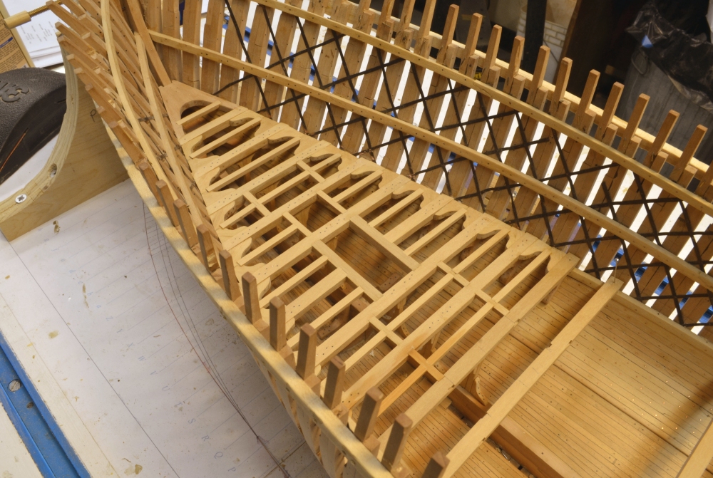
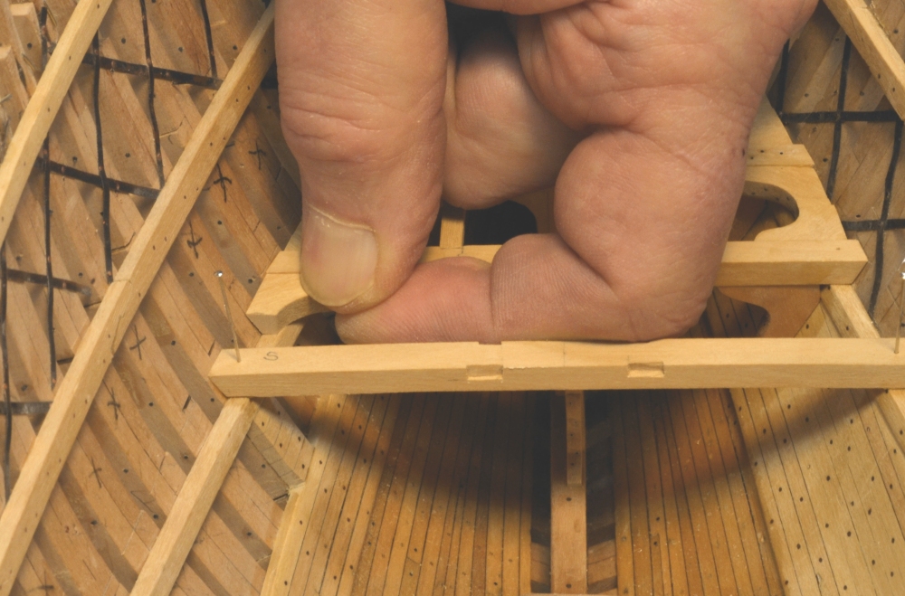
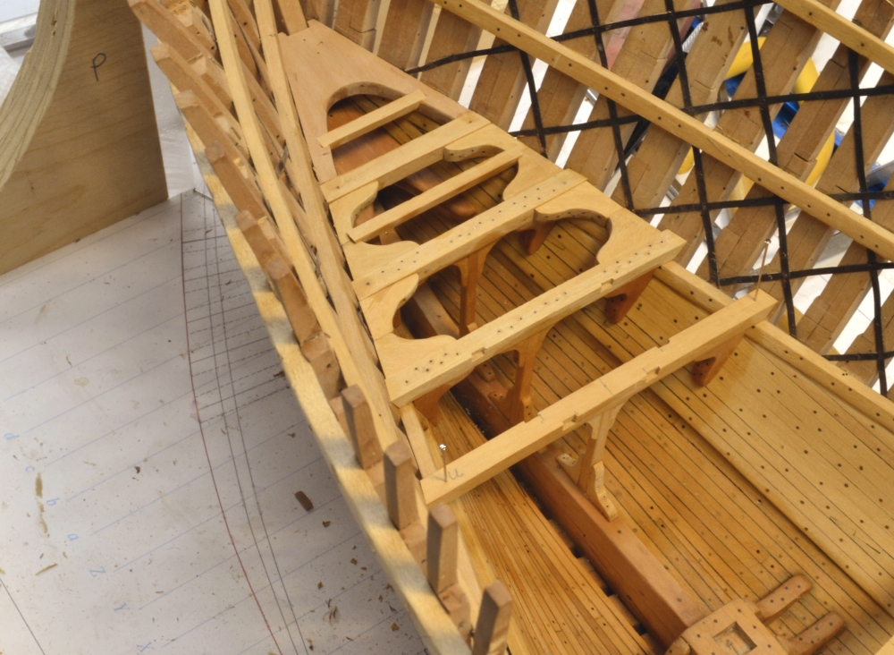
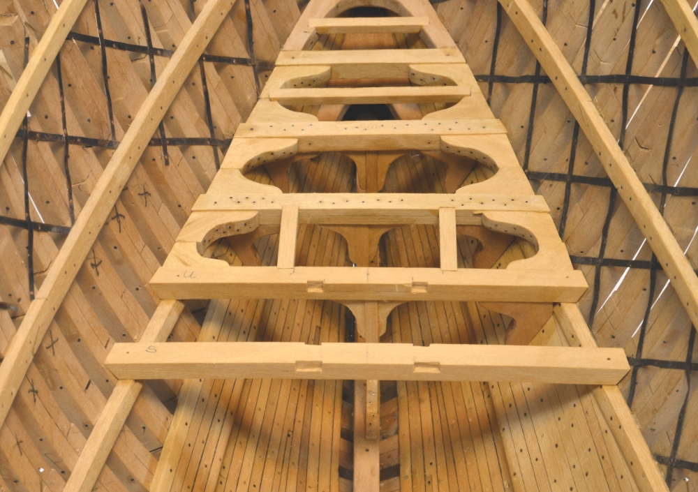
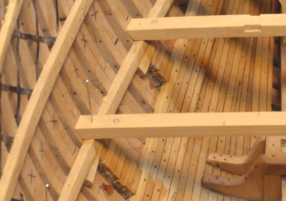
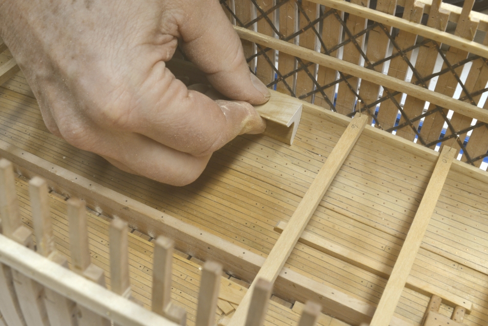
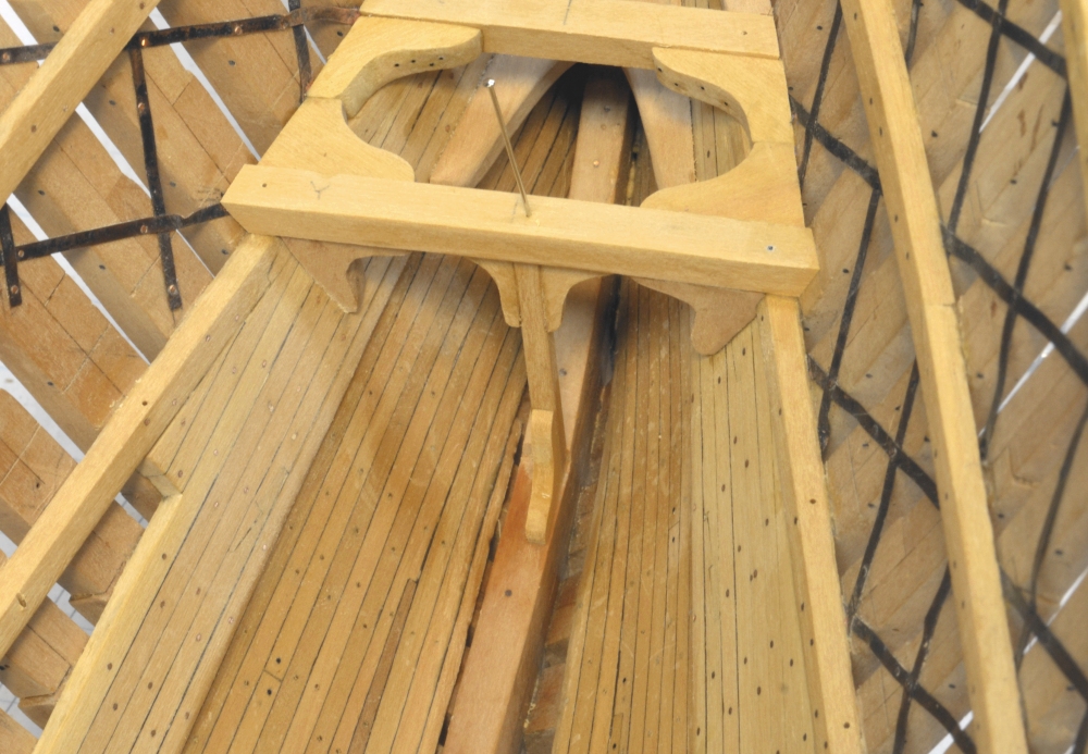
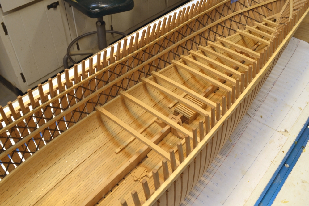
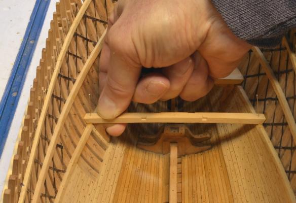
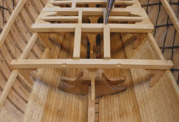
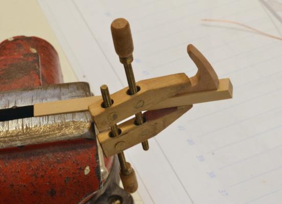
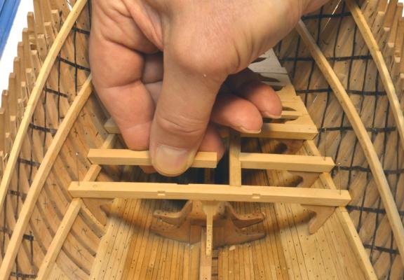
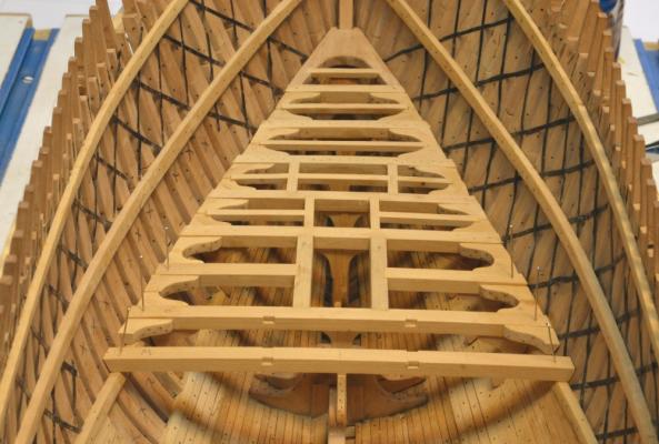
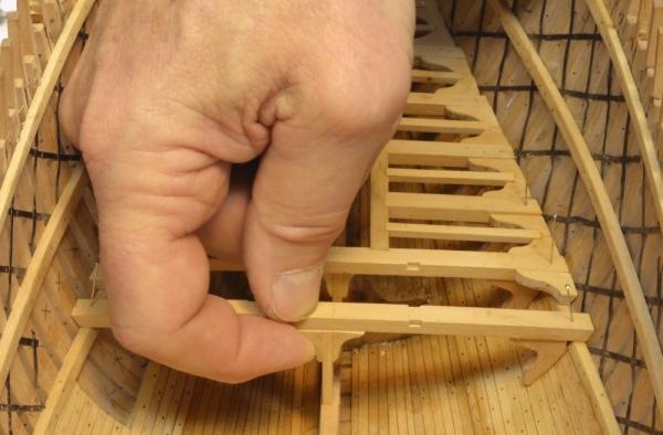
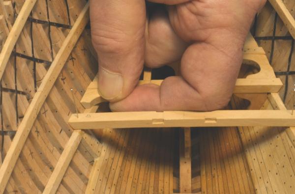
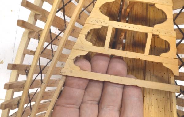
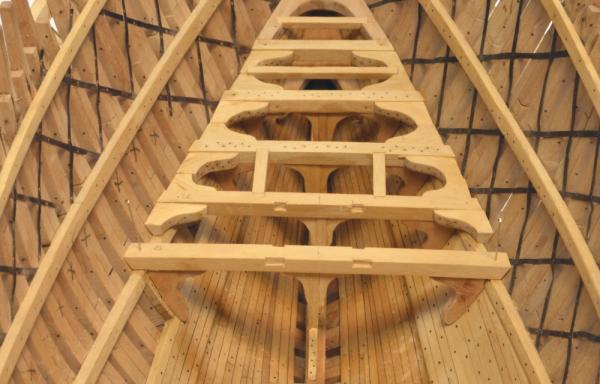
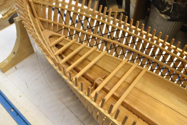
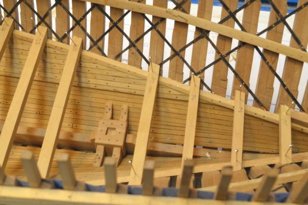
Young America - extreme clipper 1853 Part 63 – Lower deck framing continued A lot of repetitive work remains to complete the framing of the lower deck. In the first picture the beam just aft of the fore mast step has been glued down and the hanging knee on the port side is being fit to shape against the ceiling planks between two of the future view port “windows”. Fitting these hanging knees is a time consuming task. Once they are installed under a beam, the work races forward through the easier steps of fitting lodging knees, pillars, carlings and ledges. Carling scores in the next beam are then cut, the beam is glued down and progress grinds to a crawl as the next set of hanging knees get fitted. In the next picture the headers spanning the space around the mast are being fit where a full beam is omitted. These are the same depth as the beams. They fit into the scores with half-lap joints. These headers are not true mast partners since the masts were secured only at the step and at partners on the main deck. Half-beams are fitted between these headers and the side. A hanging knee is being attached to one of these in the next picture. Although the knee was shaped before the beam aft of the mast was installed, it was easier to install it on the half-beam and then install the assembly - not much room to attach the knee with both adjacent beams installed. In the next picture the end of half-beam on the other side is being fit to the frames. It will be cut to length after the other header is set. The next picture shows both half-beams installed. The next beam has been glued in and lodging knee installation is catching up. The next picture shows the pillar with its top knees attached being installed under that beam after the hanging knees were attached. In the last picture, two more beams have been set. The setting carlings and ledges is keeping pace. This deck framing is going faster than the Naiad deck framing – as I am sure it did in the actual construction of the two ships. Young America had fewer but larger framing members, the spacing was very regular, and the beams were one piece. There are more knees – 8 per beam/pillar, but except for the hanging knees they are easier to fit. Naiad's hanging knees attached to the sides of the beams were much easier to fit. Now for another pair of those pesky under-beam hanging knees. Ed

- 3,618 replies
-
- 30
-

-
- young america
- clipper
- (and 1 more)
-
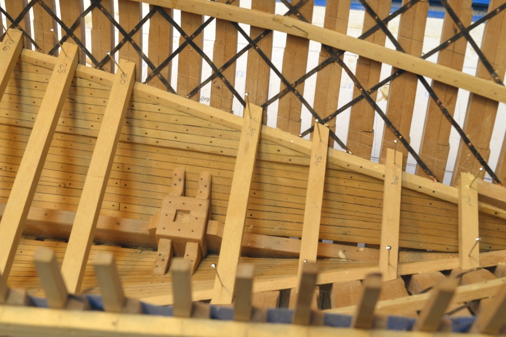
Hi Mark, The strapping extended from the floor heads up to the planksheer. I left it out in three areas where there will be view ports cut out to see into the lower hull. These will be roughly at each mast with 9 frames being removed from each from the lower futtock heads up to the middle deck clamps. These are pencil marked "x" in the photos and will be cut out later - probably after the middle deck framing. There will be two intermediate frames left in each opening. As with Naiad the lower structure will be difficult to see fromm above, so I wanted a better way to view it. Ed
-
I agree, Guy, that the time to do this is during frame erection when they can be used as spacers. Doing it now would be a major job and I doubt that I would do it at this stage. Ed
-
Daniel,the keelson is massive. The lower and middle deck beams are 17" wide by 14" deep, the carlings 10" x 7" and the ledges 9" x 7". These dimensions were taken from a description of Challenge, a Webb extreme clipper launched about two years before Young America - of about the same size. It seems a logical assumption. The scale is 1:72 - and working space is limited toward the bow as you can see in the pictures. Holding the hanging knees in place to check fit is awkward. Yesterday I re-lofted the hanging knees for all decks to reduce the amount of trimming needed on the few "generic" shapes I had been using to start. Ed
- 3,618 replies
-
- 4
-
-
- young america
- clipper
- (and 1 more)
-
Guy, it appears I dropped the ball on your question of fillers between floor frames. I believe this was common practice to prevent water from stagnating between frames where it could not be reached by the chain pumps. I installedit up to the floor heads on Naiad. These fillers were driven in tightly and perhaps aided in resisting compressive hogging stresses inhe lower hull. I did not find a definitive original source for this. I would install them, butthe choice is always yours. Sorry for the delay with this. Ed
-
Thanks again for the comments and likes. I appreciate them very much. Doug: I look forward to hearing more about your planned Webb model. E&T: From what I have read I believe you are quite correct on Canadian timber exports to Englan during the period. Alan: Young America had three decks - the top being the main weather deck. At the stern there was a poop deck and below it a cabin deck at a height midway between the main and middle decks. There was a forecastle at the bow. Ed
-
Nice work as always, Remco. I like the tapering guide. Mark, I used straight black acrylic ink on Naiad, thinned to a stain, then applied to semi-opaque to let the pear color come through. However, in the end, it looks pretty black. ed
-
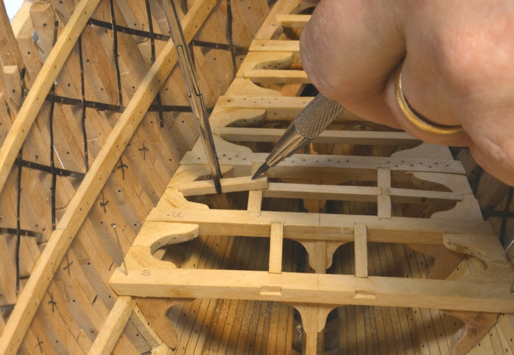
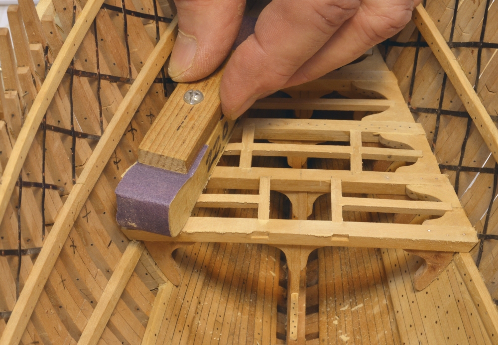
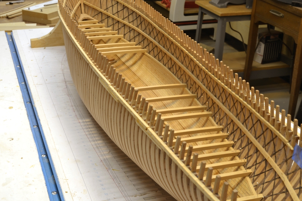
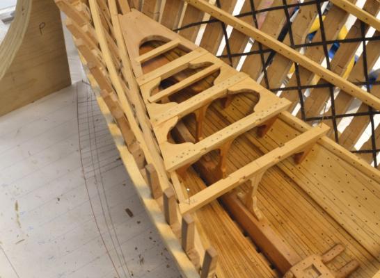
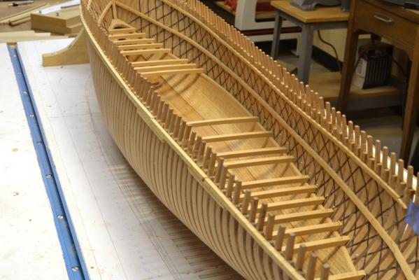
Young America - extreme clipper 1853 Part 62 – Lower deck framing continued Thank you all for the comments and the likes on the last posts. Work continues. Once the deck beams are fitted, the deck framing is all about knees. Below is a set of lodging knees that have been fitted between two beams. Monofilament dummy bolts have been CA glued in and sliced off flush. The knees now will be sanded to remove all trace of the CA and to round off the bottom edge. Note in this picture the two dashed lines on the drawing running parallel to the side. The upper line is the inside edge of the waterway. This will cover the butting of the knees as well as the ends of the ledges. In the next picture one of the generic-shaped lodging cut earlier knees is being fit. For the lodging knees this is mainly a matter of beveling the edge to fit the frames and to adjust the fore and aft width. The next picture shows the fit from above. In the next picture the forward pair of lodging knees and the hanging knees under the next beam have been installed. Fitting of the hanging knees involves quite a bit of trimming of the original cut-out shapes due to the change in hull curvature. I suspect a bit more lofting work would have been helpful. I am following up the beam installation progressively with the carlings and ledges. In the next picture a ledge is being marked for cutting – held by a surgical clamp. The ledges are not rounded, so they need to be faired off to match the beams. A small sanding block is being used in the next picture to fair off the top of all the framing. The last picture shows the framing completed thus far. The waterways will put a neat cap at the side on the intersection of all these deck members with the frames at the side. Ed


- 3,618 replies
-
- 32
-
-
- young america
- clipper
- (and 1 more)
-
Thank you, all, for your comments and likes. Druxey: Yes, many knees. I'm glad they are not all as difficult to fit as the hanging knees, especially those fore and aft. The model is a big project for sure, but I am falling in love with this ship - as did, so it seems, William Webb. E&T: Black monofilament is perfect for simulating flush rivetted iron bolts. Regarding the wood structural elements: In the 1850's America had a lot of wood and not much iron production. Most iron had to be imported from England. Production capabilities for good malleable iron were limited at this time. Hence, most American built ships in this period were predominantly wood. The situation was reversed in England where the RN had basically depleted timber resources by the end of the 18th Century, while expanding facilities for production of good quality iron - ushering in the era of iron in ships. Of course there are many tons of iron bolts in Young America. The offset pillars are interesting. I don't know if they were staggered or all put to one side on a deck. I decided to stagger them. They permit through, tie-bolting of the pillars above, allowing all to function in tension as well as compression. One more structural measure that helped these ships weather the forces of the Cape. Ed
- 3,618 replies
-
- 4
-
-
- young america
- clipper
- (and 1 more)
-
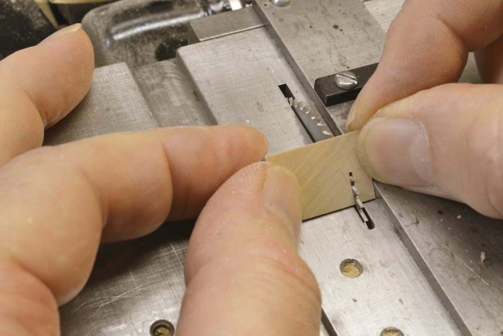
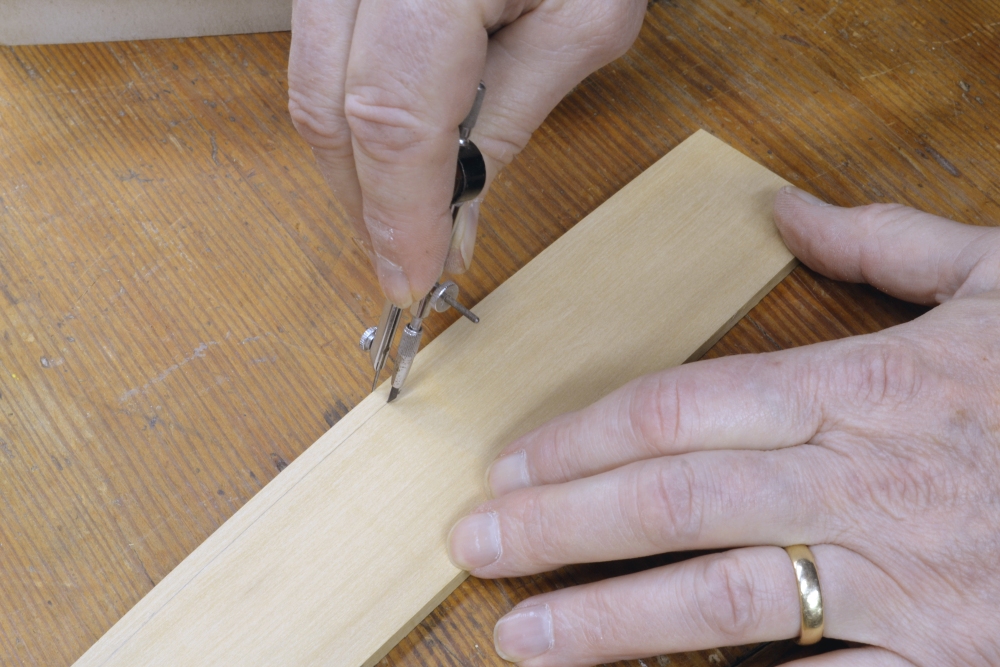
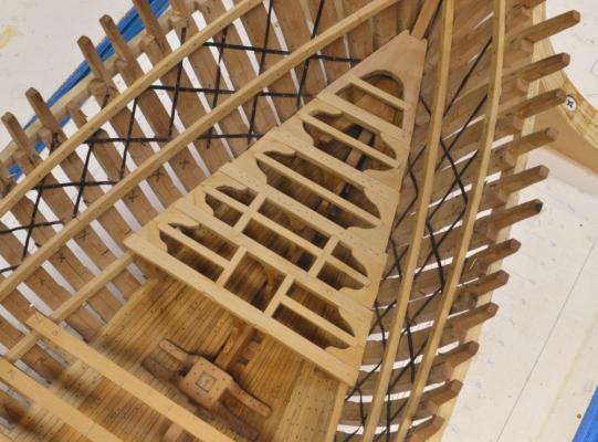
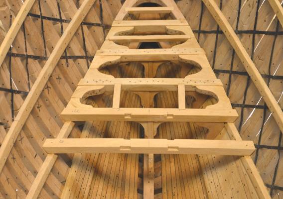
Young America - extreme clipper 1853 Part 61 – Lower deck framing The first picture shows the first four beams of the lower deck installed. The beams, lodging knees, pillars and pillar knees are Castelo – representing hard pine. The hanging knees are pear – representing oak. Beams 2 and 3 have their bolts installed – down into the hanging knees, pillar knees and deck clamps. The off-center staggering of the pillars can be seen in this picture. Wax finish has been applied to surfaces under the first three beams. Two forward ledges are installed. Beams 3 and 4 have been scored for carlings. The next pictures show the cutting of the scores. First, centerlines were marked on each beam and the carling locations marked out from those lines. The depths of the scores were then marked with a compass. In the above picture a cross-grain plunge-cut is being made in the beam. In the next picture the score is being pared out after the three plunge-cuts. The depth is set by eye. In the next picture a piece of carling stock is being used to check the fit. After the beams are set and glued into position, the hanging and lodging knees are fit. Dummy bolts in these knees are then installed using black monofilament as shown below. A razor blade is being used to slice off the monofilament after gluing with CA. The knees are then sanded smooth before installing. The next picture shows a pillar and its top knees being prefabricated. These knees also receive bolts as above. The knees at the bottom are installed on the keelson after the pillar is set. The next picture shows beams 2,3 and 4 installed and the next one (beam S) positioned. Note that the lodging knees are set slightly below the top face of the beams. This allowed air circulation under the decking and the massive waterways that will cover the beam ends. The tops of the ledges are also slightly higher than the tops of the knees – to match the beams so the decking will lie fair. Two carlings have been installed. Ledges will be installed between all these beams. The staggering of the pillars is more evident in this picture. Note that no hanging knees are installed at the frames - marked X on the port side. Those will be removed for the view port on that side - later. In the next picture pieces of bilge ceiling have been glued to the frames that will not be removed for the view port. After bolting, these will be trimmed off flush with the fore and aft faces of the frames. These are needed to allow hanging knees to be installed under these beams. The three frames between these beams will be removed later between the top of the lower futtock heads and the middle deck clamp.. Ed


- 3,618 replies
-
- 21
-
-
- young america
- clipper
- (and 1 more)
-
Thanks, everyone. Daniel,the scroll saw blade has 12.5 tpi. I was running it a fairly high speed but it didn't seem to matter much. I have cut thicker pieces, up to 1 1/2" at least. It is a good quality DeWalt saw. Bruce, I had not appreciated just how stout everything was, until starting to frame this lower deck. Even making the drawings did not bring this home fully. Those 17" wide by 14" deep deck beams rival those on a 74. Carlings 10" wide x 7", ledges 9" x 7". Pillars on every beam were tie-bolted through. Wait utill we get to those 15" x 15" waterways. There is no question that these ships were built to be driven. McKay's ships were even beefier. I think the submerged channels were not untypical. The frequency of these ships losing their upper masting is further testimony. Iron men/wooden ships - to say nothing of courageous passengers. Ed
- 3,618 replies
-
- 2
-
-
- young america
- clipper
- (and 1 more)
-
Mark, I use needle-nose pliers to push the pins in , gripping them just above the point, maybe 1/8" or less to avoid bending. I use pliers to extract them as well. I will check the drill size. I know the pins are .021" pleating pins. Ed
-
Yes, druxey, there are quite a few - avg. 8 per beam on the lower deck counting the four for each pillar, 34 beams, minus a few at the view ports. Thats around 200 knees for the lower deck. Definately justifies a production process. Wish their were a process for the ten or so bolts in each. Ed
- 3,618 replies
-
- 3
-
-
- young america
- clipper
- (and 1 more)
-
I was actually thinking more about resistance to splitting. Ed
-
Ben, it looks scarier than it is. I use push sticks for a lot of this close work and were it not for the limited blade height on the Preac, a nice little specialty sled could be made to handle these - the time savings would easily cover it. However, I believe the key factor is your concentration - whatever aids are used - or whatever size the saw - or router, or whatever. When the switch goes on there should be only one thing in mind - finger proximity to the blade. When you feel that focus slipping from fatigue or lack of concentration, do something else. I never work at night. These knees could also be easily sliced off with a hand saw. Ed
- 3,618 replies
-
- 4
-
-
- young america
- clipper
- (and 1 more)
-
You are much too kind, druxey. Actually I was thinking more about this later, specifically the effect of scale. compared to 1/48 planks are a third smaller in thickness and width at Mark's 1/64 and 50% percent smaller at my scale on YA of 1/72. Cross-sectional area at 1/64 is 44% smaller and at 1/72 55% smaller. If I add that on YA the planking is a lot narrower - 6" to 7" wide, one could conclude different approaches to bending and shaping may be in order. Planks at these small scales are pretty flexible, especially in narrow width. Just something else to chew on when thinking about the process. Couple of other thoughts on pinning: I find that Castelo "boxwood" is more prone to splitting than genuine box or pear, don't know about holly. At narrow widths this needs to be considered. Also nickel-plated dressmaker pins do not stain the wood - unless they severely bent. Then the nickel flakes and the planking can be stained. I had two such cases on YA's ceiling planking. If a pin bends severely when being pushed in, remove and replace it. Love planking. Ed
-
As those who closely read my posts probably know, where clamping is in the least bit awkward, I use pins. I drill undersized pin holes through the planks into the beams where treenails or bolts will be placed, then hold the glued planks down with the pins pushed into the holes, removing them when the glue is set. There are often situations where clamping is impractical. I don't have the stamina for druxey's multi-step approach - although it is probably the best if planking perfection is the goal. Ed
-
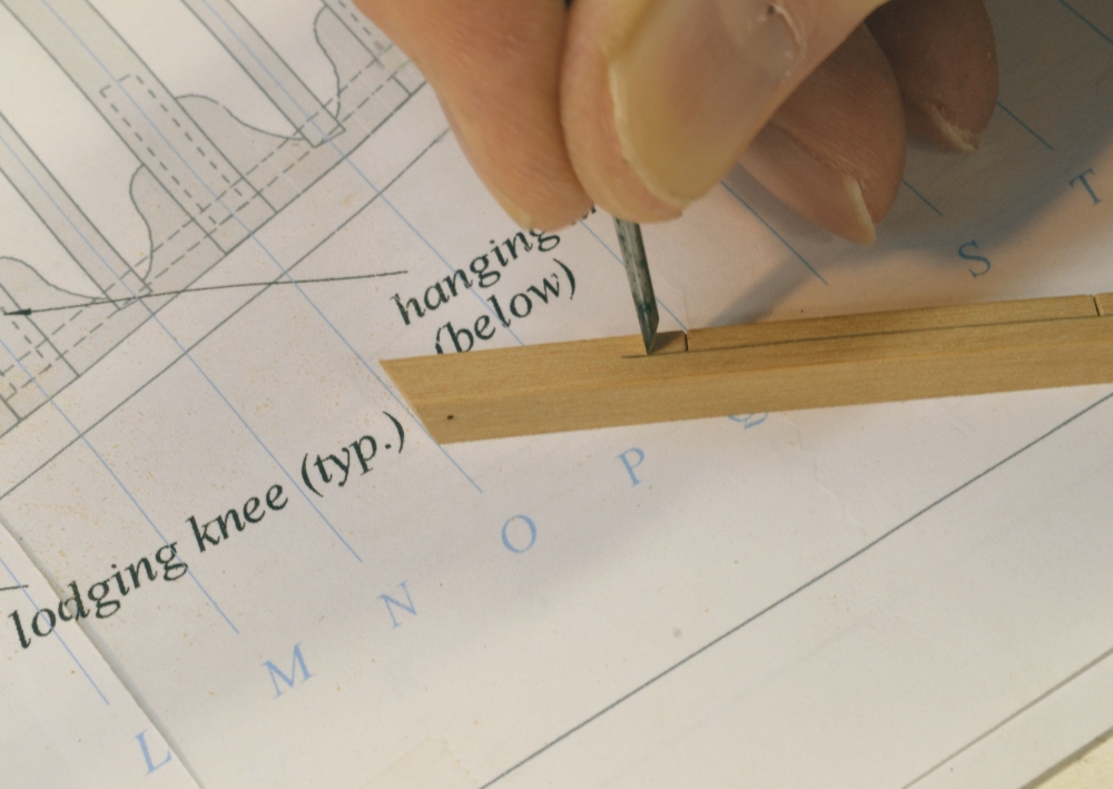
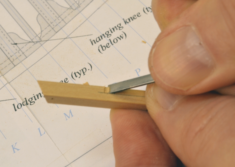
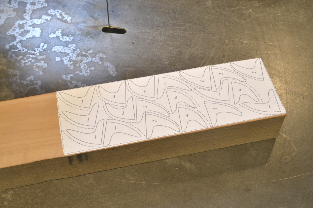
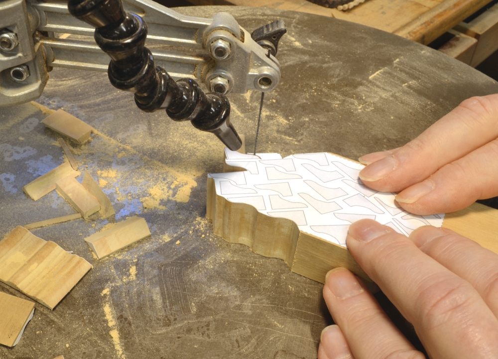
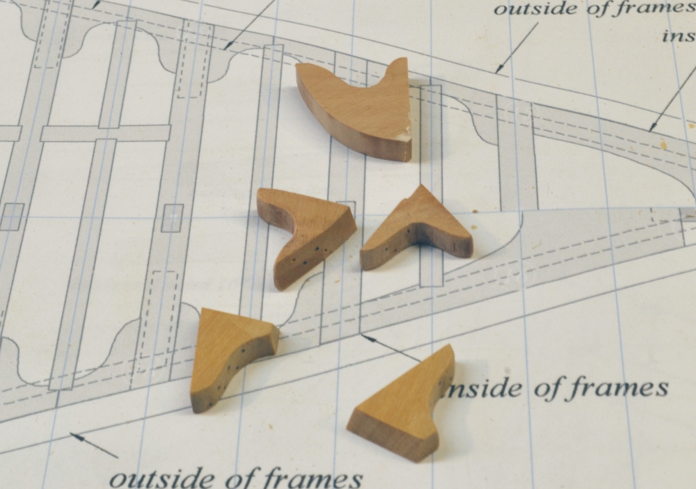
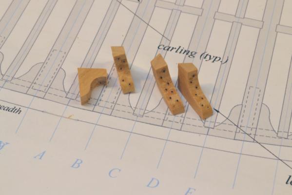
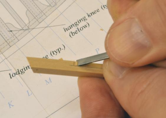
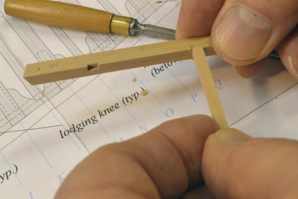
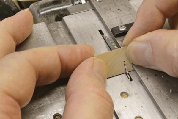
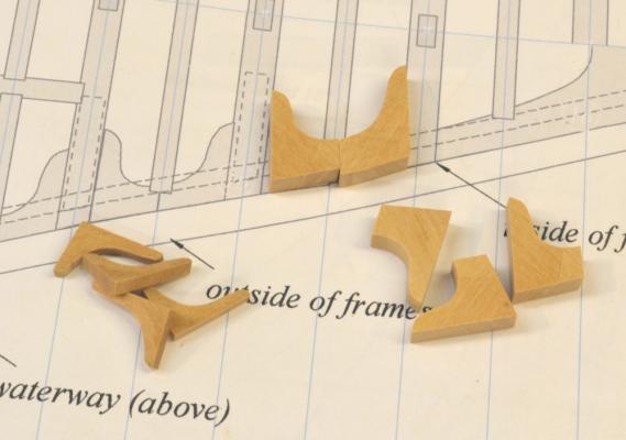
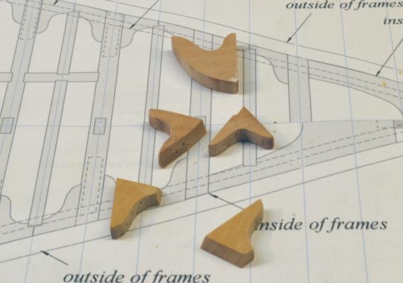
Young America - extreme clipper 1853 Part 60 – Knees Historical note: It is doubtful that knees were made for Young America at the Webb shipyard. There was enough building activity at the New York yards to generate profitable local business opportunities in the making of various components and selling them prefabricated to the shipbuilders. Knees were one such commodity, offered for sale in oak, hard pine, hackmatack, etc. - from $2 to $10 each, or $1.50 per inch of thickness for large sizes – according to one supplier’s price sheet. This dealer also sold floor timbers, futtocks, rough timber and plank. The pre-made knees, in a variety of angular shapes, were probably then trimmed to final size and shape at the yard. Most of the work in this post is analogous to the work of the ship timber supplier – making a large quantity of knees that will later be fit to specific locations in the lower deck framing. Patterns for representative shapes for hanging, lodging and stanchion knees were lofted from the drawings. The shapes of the central hanging knees were also lofted, but shapes toward the ends merely estimated. The shapes were then arranged on roughly 2” x 4” pattern sheets. These were then pasted to a 1” thick slab of wood – pear for the oak hanging knees and Castello for the hard pine lodging and stanchion knees. The hanging knee pattern is shown below. Extra stock was left on the back of the vertical hanging knee arms to allow for fitting and beveling to the hull shape. The shapes were then cut out on the scroll saw as shown below. The above picture shows lodging knees being cut out. The next picture shows a hanging knee shape being checked for general fit on the bilge ceiling near midship. Next the straight edges of the knees were cleaned up on the disk sander and then ripped off to thickness on the circular saw – shown below. This takes two passes on the Preac saw due to its limited cutting height. Below is a picture of some 12” thick lodging knees and some of the smaller 6” thick knees for the hold stanchions (pillars). Hopefully, these generic shapes will be sufficient to make the final knees. Some, especially the hanging beams near the ends, will need considerable adjustment to fit. The following picture illustrates the amount of modification needed on the hanging knees for the beam frame Y. The generic starting point shape is at the top with the final hanging knees below it. Lodging knees are a better fit to start. The last picture shows the installation of beam Y near the bow. These first two beams have no carlings, so I could proceed with them to test the installation process. This shows all of the knee types. The lodging knees are butted together – one of a number of configurations used. There will be a ledge set into these where they butt (frame line Z) to span the breadth. Note that the stanchion is set off the centerline. The stanchion above will be set to the other side. This allowed the stanchions to be through bolted vertically to resist tension as well as compressive forces between the deck beams. The hold stanchions were secured for tension with the knees top and bottom. This first beam was somewhat difficult to fit. Finger space is limited and the angles on the hanging knee surfaces are acute and required many test fittings. I am still working on the sequence, but so far it is 1) install the beam and bolt into clamps, 2) install dummy bolts in the knees, 3) install hanging knees, 4) install lodgers, 5) fit and install the post with the upper knees glued to it, 6) install lower post knees, 7) bolt stanchion through beam, 8) install dummy bolts in outside of frames, 9) bolt knees to the beam - a lot of steps. Install means glue. I see a lot of work ahead before the lower deck framing. Ed


- 3,618 replies
-
- 31
-
-
- young america
- clipper
- (and 1 more)
-
She looks as good upside down as right side up, Mark. Beautiful work. Ed
-
Very nice, Sherry. Nce cean, proportionate work. Glad the LOS athe copper worked for you. Ed
-
Thanks, everyone, Primarily cargo - California trade, Rob. Ed
-
Thanks, everyone. Eight hours a night, Peter.
-
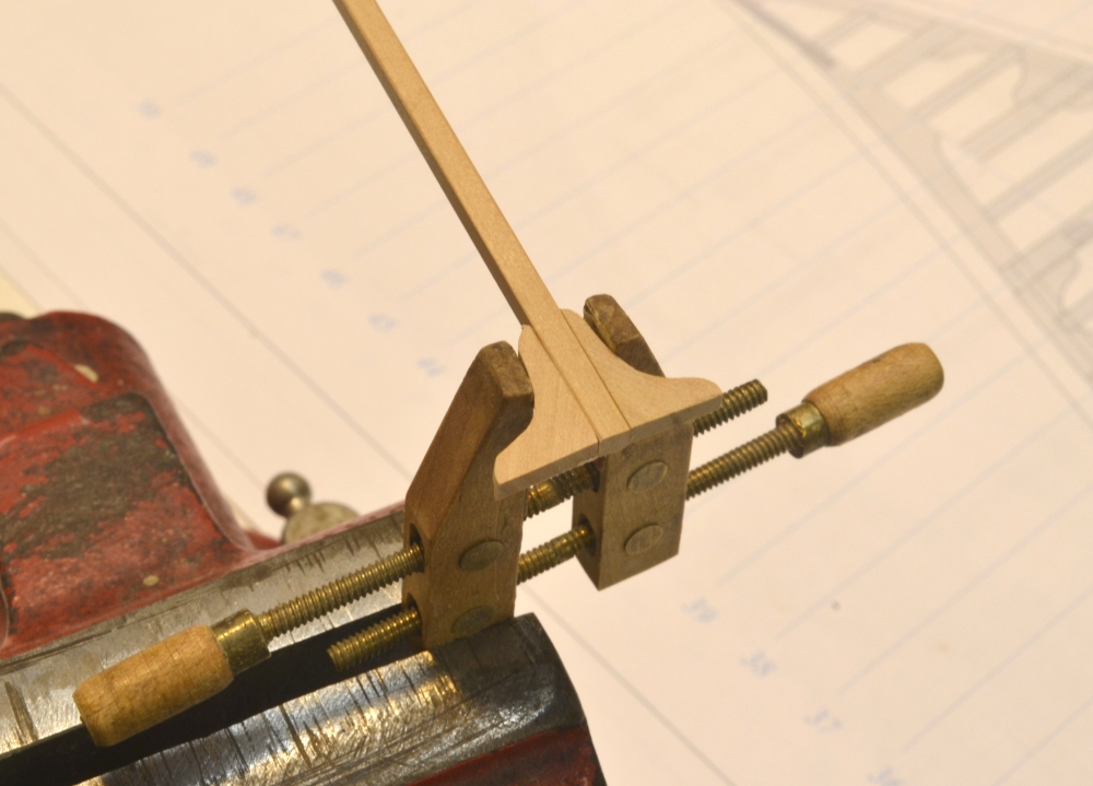
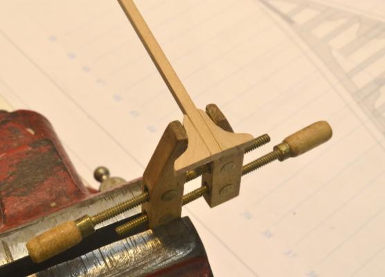
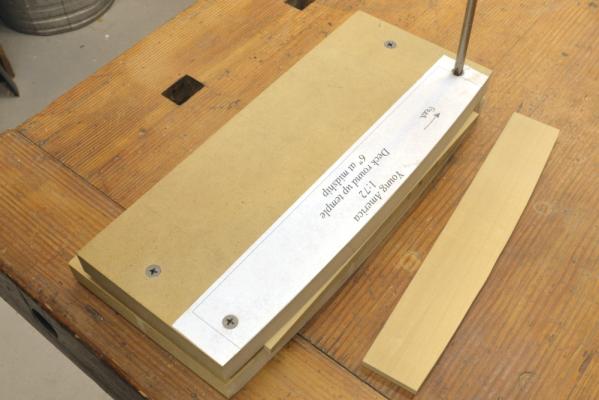
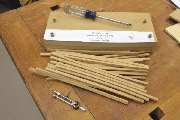
Young America - extreme clipper 1853 Part 59 – Lower deck beams With a marathon effort all of the monofilament bolts for the iron strapping were installed into the outside of the hull frames – except for frames that will be cut out for the view ports and for areas that will be planked over. The lower hull was then sanded to remove all traces of the CA glue used on the bolts. To relieve some of the tedium of bolting, the lower deck beams were fabricated. I used the method developed for the Naiad beams – including the recycled Naiad template-clamp shown in the next picture. In the picture a piece of 17” (~0.236”) thick stock is being clamped. All of the decks on YA were rounded up 6” at midship – a simplification vs.18thC RN. A template was lofted with this curvature and pasted to the clamp. The clamp faces were then shaped to the curve using a disk sander. A more elaborate process was used on Naiad. When clamped in place as shown, a flush trim router bit with a bearing was used against the template to form the curve on the top of the beam. The router leaves a perfectly finished surface. The piece to the right has had a beam sawed off (described below) after rounding. It will soon be clamped and a new top surface routed. The next step after routing is shown below. The depth of the beam is drawn on the routed blank with a compass that has its point extended to ride on the side of the piece. The beam is then parted off near that line on the scroll saw. A new top surface is then routed on the remaining stock. Finally the cut off beam is passed – upside down – through the thickness sander to yield the final depth of 14” (~0.194”). The next picture shows the set of lower deck beams, ready to be cut to length and fit into place. The process for making rounded-up beams was covered in detail in Naiad, Volume II, including alternate methods that can be used in the absence of a router table. Naiad’s beams were more complicated in that they were made in two pieces with tabled scarph joints. These were simpler. Setting was also simpler. YA’s beams were all centered on every other frame joint line. The next picture shows some of the forward beams fitted and pinned in place. These beams were pretty massive – 17” wide and 14” deep. There was nothing skimpy about the construction of these ships. The first few beams fore and aft were smaller – 15” wide. The next picture shows the difference in width on the aft three beams. Hard pine was used for Young America’s deck beams and many other structural components. Also known as longleaf pine, the trees grow mainly in the southeastern United States. The wood weighs about the same as white (or English) oak and has about 90% of its strength. As mentioned before, I am using Castelo to simulate this species. The next picture shows the beams from the main hatch aft. The larger spacings are to clear the hatch, the water tanks and the masts. Stout headers (aka partners/carlings) and half beams will be installed in these spaces. The last picture shows the current state with several central beams still to be fit. When all the beams are sized and pinned in place, centerlines will be scribed on each. Carling locations can then be marked. After cutting scores for the carlings, pillars and knees will need to be made before any beams can be installed. Ed


- 3,618 replies
-
- 27
-
-
- young america
- clipper
- (and 1 more)
-
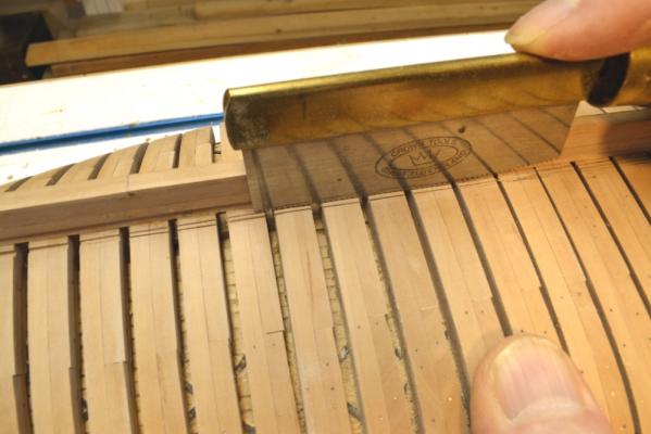
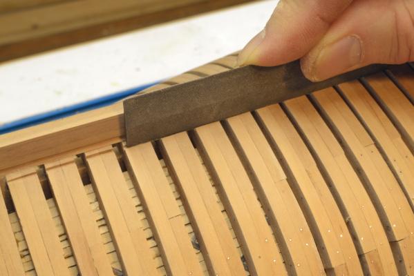
Again, thanks for all the comments and "likes". Here is a link to the Crown veneer saw on Amazon http://www.amazon.com/Crown-England-Veneer-Genuine-Rosewood/dp/B00EW69F6S Its a nice little tool that I have not used much, but it seemed just right for this job. The file in the picture is also very useful. It is a type used to sharpen Japanese style saws. It has very sharp edges. Here is a link for these. http://www.highlandwoodworking.com/search.aspx?find=feather+files I'm afraid I am a bit of an incurable tool collector. Ed
- 3,618 replies
-
- 4
-
-
- young america
- clipper
- (and 1 more)
-
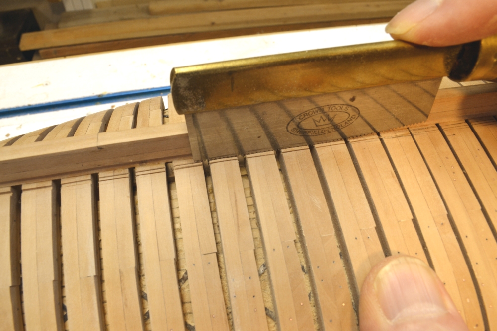
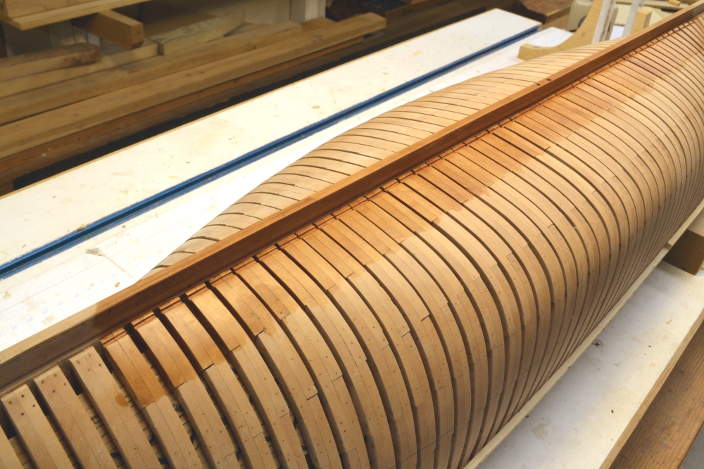
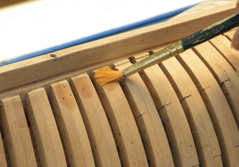
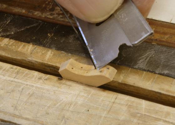
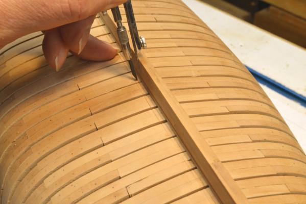
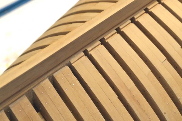
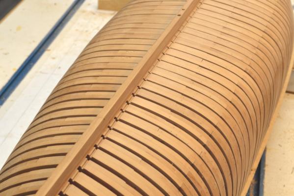
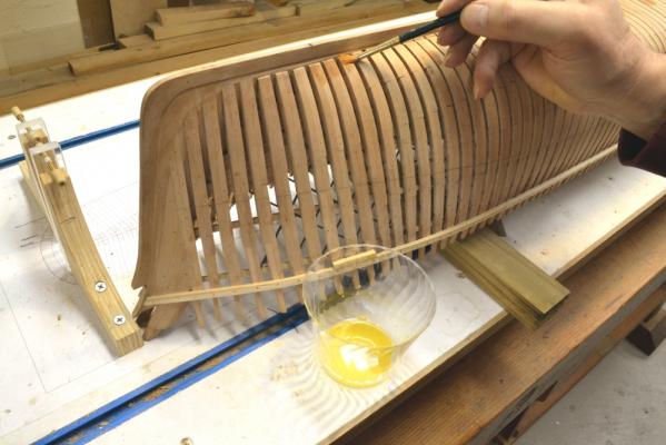
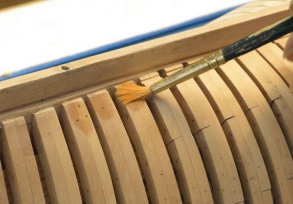
Young America - extreme clipper 1853 Part 58 – Limber channels Historical note: Young America, like most of her contemporaries, employed piston-type suction pumps to remove bilge water. The reciprocating pump pistons were driven by muscle power applied to large circular crank wheels on the main deck. Unlike the earlier chain-type pump that could only reach into a shallow sump cut into the floor timbers in the well, the suction pump could suck out water through a relatively small diameter pipe. This pipe could extend all the way down between the floor frames to the inner face of the outboard bottom planking – in this case the garboard strake - right next to the keel. The ability of the suction pipe to reach to the very bottom of the floor frames eliminated the need to pack the spaces between these frames – as was traditionally done to prevent stagnant water between frames and to inhibit rot in the lower timbers. Without this packing, air could circulate between the lower timbers. Lowering the suction point could also help keep the hold less wet. Provision still had to be made to permit water to flow to the pump suction. This was done by creating limber channels through the outboard faces of the floors. Each frame was notched to allow water to flow to midship. These channels were about 4” x 6” in cross section – located a few inches outside of the keel on both sides. These channels were often – perhaps normally – fitted with chains that could be used to break blockages. Debris could be cleared from above between frames by removing the limber boards next to the keelson. At the ends of the ship, triangular openings under the feet of the half-frames provided passages for water into the ends of the limber channels. I debated whether to include these limber channels on the model. They will be difficult to see. Cutting them also runs a risk of damaging the lower frames. To be consistent with the other levels of included detail, I decide to do it. In the first picture, the sides of the channels are being marked out using a compass with an extended lead, guided by the side of the point against the keel. I imagine that in practice these notches were sawed out before the frames were assembled. I elected to do it at this stage to help assure that the notches would run in straight lines. The next picture shows the sides of the channels being sawed out using a veneer saw. The veneer saw has straight (unset) teeth in a curved blade. This turned out to be an ideal tool for this. It is relatively easy to cut a straight line. A small (1/32”) chisel was then used to clear the material between saw cuts. Some different files were then used to clean up the channel. A straight, knife-edged file is being used in the next picture to shape the inside corners. The next picture shows the aft end of the channel on the port side. The channels end at the last full frames. In this picture the half-frames aft of the channel have squared off ends that form the triangular channel mentioned above. The next picture shows most of the channel on the port side. The channels were formed on both sides of the keel. I had intended to next finish the lower hull up to the lower futtock heads, but because more bolts will be needed later for the lower deck hanging knees I decided to finish only the full frames up to the floor heads at this stage. This area was given a final sanding and some polishing with Scotchbrite. The bolts in this area were then blackened with liver of sulfur as shown in the next pictures. I included this picture to give some idea of the LOS batch size and concentration. The next picture shows some bolt heads being blackened with a brush that is only damp with solution. Less is better. The bolt heads turn black almost instantly from the damp brush. In the last picture wax-turpentine solution has been applied up the floor heads on one side. Virtually all of this first coat was absorbed into the wood. There will be more coats later. Now back to installing bolts above the floor heads - and making deck beams. Ed

- 3,618 replies
-
- 22
-
-
- young america
- clipper
- (and 1 more)