HOLIDAY DONATION DRIVE - SUPPORT MSW - DO YOUR PART TO KEEP THIS GREAT FORUM GOING! (Only 72 donations so far out of 49,000 members - Can we at least get 100? C'mon guys!)
×


EdT
-
Posts
2,214 -
Joined
-
Last visited
Content Type
Profiles
Forums
Gallery
Events
Everything posted by EdT
-
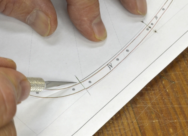
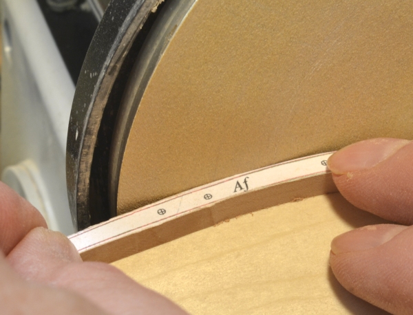
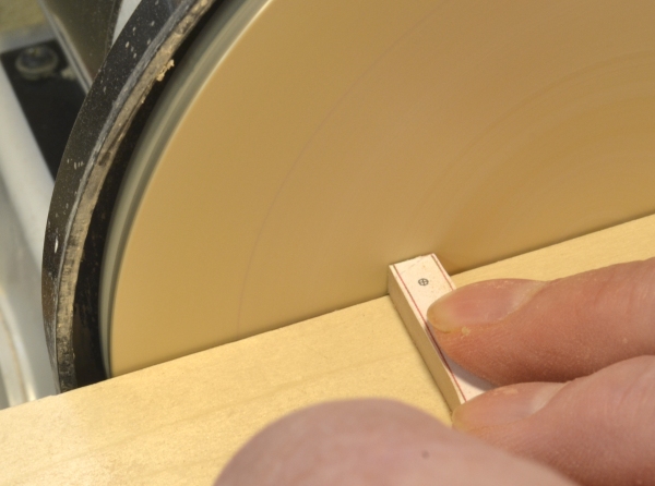
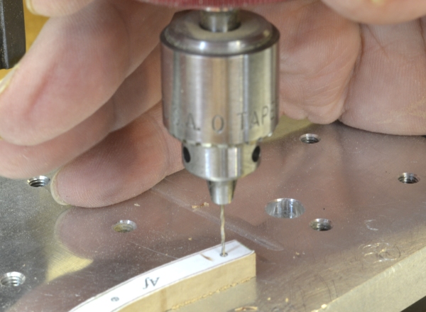
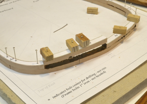
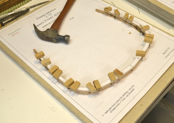
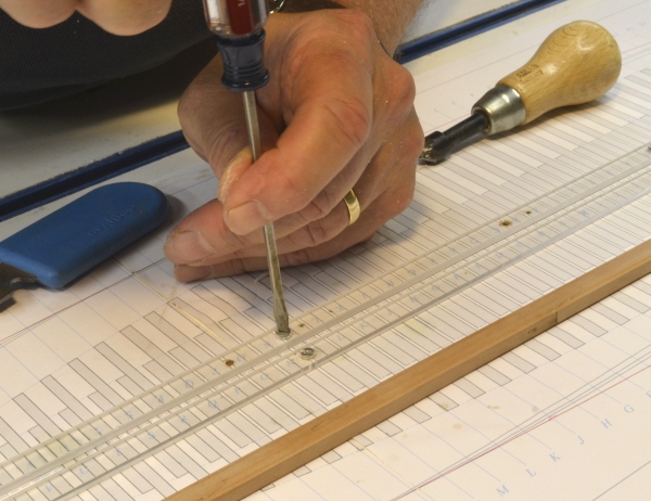
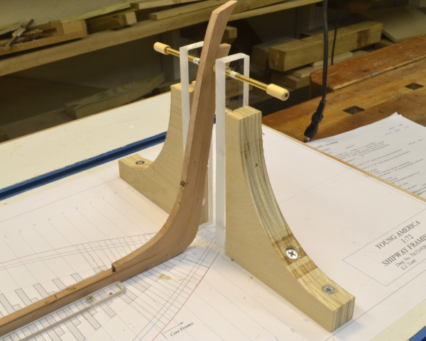
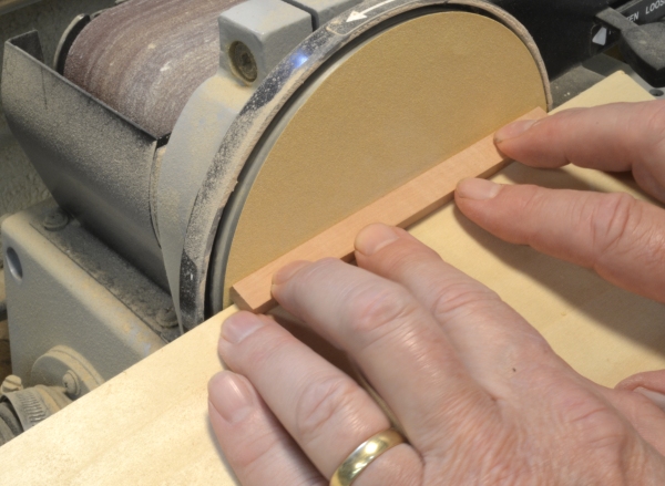
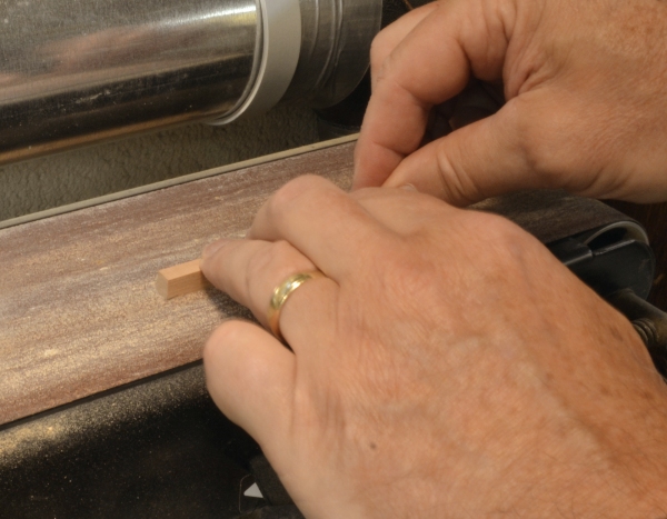
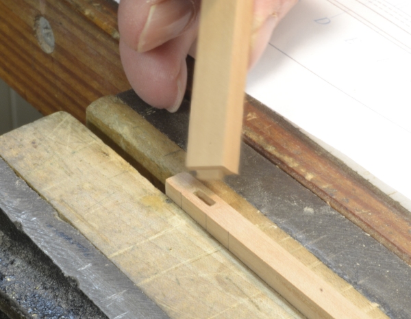
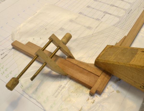
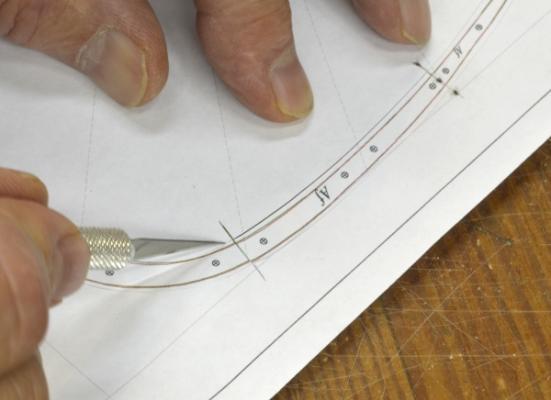
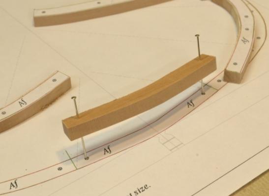
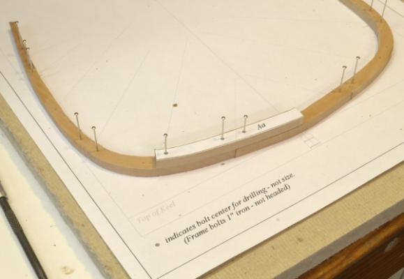
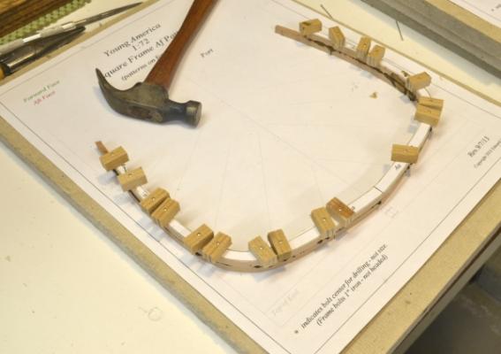
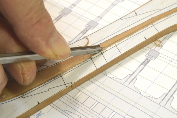
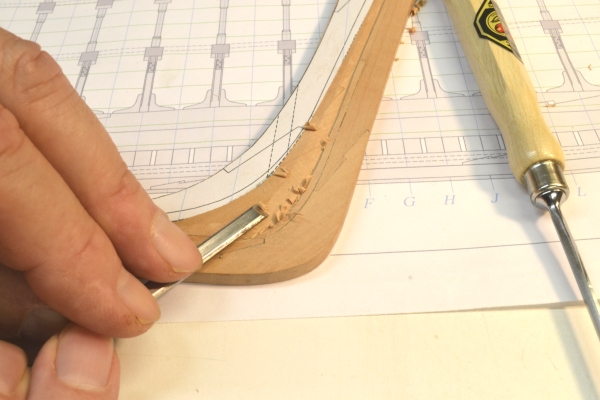
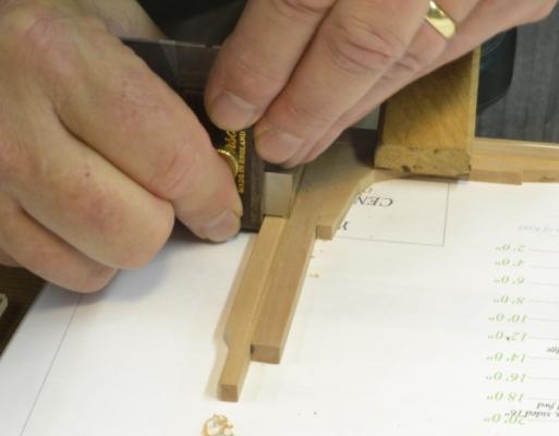
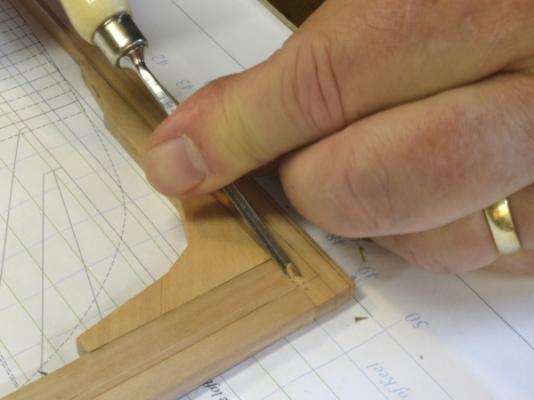
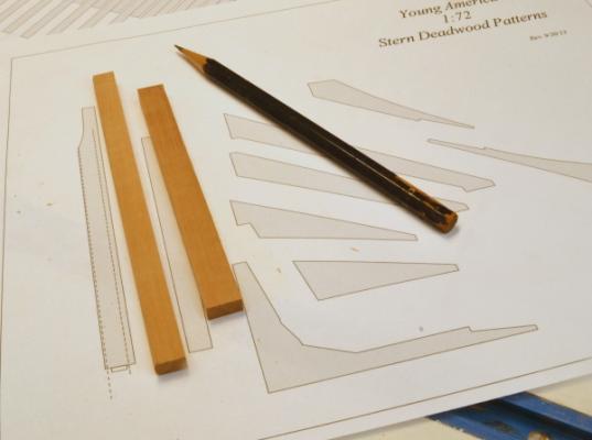
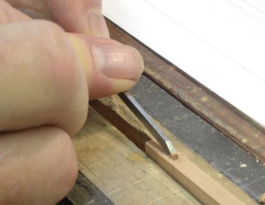
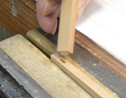
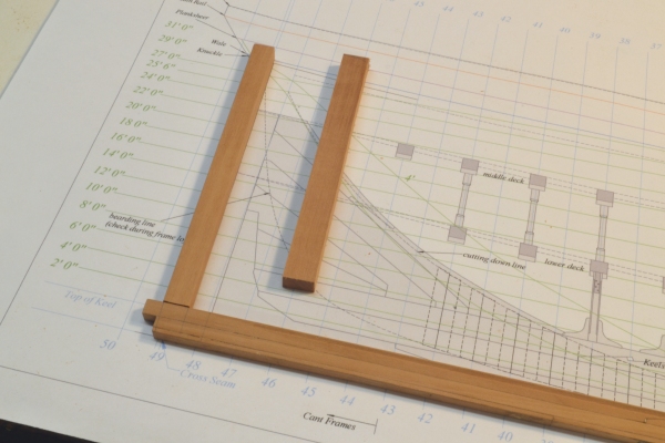
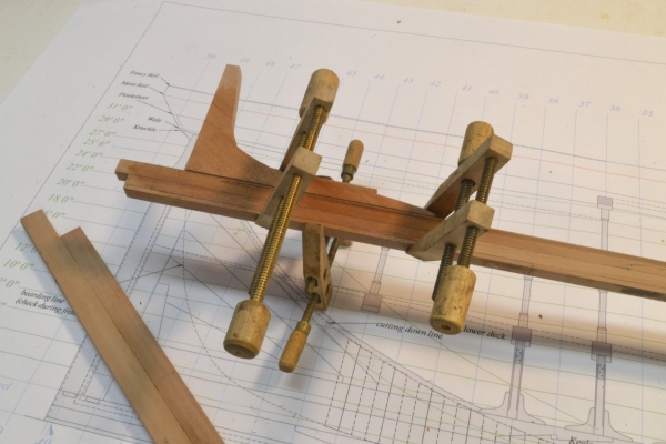
Young America - extreme clipper 1853 Part 12 –Frame Assembly 1 American Clipper Note: Rated tonnage rules based on length, breadth and depth of ships, used to assess tax on cargoes, retarded the development of fast merchant ships for a hundred years, perhaps longer. Shippers, wanting hulls that could carry more than their rated tonnage - to reduce taxes on actual tonnage - created demand for the slow, “floating bathtub” designs that prevailed to mid-19th Century. High profit margins, the result of two gold rushes and the lucrative China trade flipped the coin – enter the fast sailing clipper. Extreme clippers, with their long sleek hulls, stiffened with massive internal structures, were often incapable of carrying even their rated tonnage. The higher profit margins and the faster voyage times made the ships profitable in spite of the tax disadvantages. Tonnage laws were eventually revised. With the keel assembly constructed and set up on the shipway, the next major task will be framing. There are many frames and I expect this will take months. Earlier I described a frame assembly process trial and decided to proceed based on that. In this part, assembly of one of the first frames is described. The first picture shows the pattern being cut up into the segments to be pasted on to 14” thick pear stock. This is the siding of the floors – the thickest pieces. I intend to make all the frame timbers this size then machine off the upper futtocks (and the patterns) to the correct sidings after assembly and initial beveling. The patterns include accurately placed bolt holes. These are indexed on both the fore and aft frames in the pair to be used to align the parts. All the frame pairs on the ship are bolted together on the respective frame line. After cutting out all the pieces for the pair – in this case the fore and aft frames at line A – the outside profiles were sanded back closer to the line on the disk sander as shown below. The ends of each timber were also sanded back square to the cut line on the pattern segment as shown in the next picture. This sanding needs to be precise so the timbers butt neatly. At this stage they are left slightly oversize. In the next picture, bolt holes in one of the timbers is being drilled. These holes need to be precisely located so the parts will fit accurately. The holes are, of course, first center marked as accurately as possible. In the next picture the floor of the forward face is being pinned to the pattern with the pattern side down. The pins are centered as shown on the bolt hole centers on the pattern. The pins and holes are sized for a sliding fit. After fitting and pinning all the forward frame timbers to the pattern, the aft frame timbers are pinned through the holes with the pattern side up as shown below. After all the aft timbers have been fitted and pinned on top of the forward frame, final assembly can begin. The next picture shows the second of the two lower futtocks to be glued down. The lower futtock to the right has been glued and nailed down tight with the pins. Small blocks of soft wood were used to allow the pins to be removed more easily and without damage to the frame. The futtock to the left = being glued - was set with its pins in the holes before the dark glue was applied. In the picture it is ready to be nailed down into place. In the next picture all of the aft frame timbers have been progressively glued into place. When the glue has dried the frame will be removed for some clean-up, beveling, machining to the correct sidings at each level and bolting. I will show this in the next part(s?) There will be 50 full square frame pairs like this one to be made. This excludes the 19 pairs of half frames and the 11 pairs of cant frames at the ends of the ship. Ed


- 3,618 replies
-
- 14
-

-
- young america
- clipper
- (and 1 more)
-
Thanks, Guy and Allan. Good to see you both at the conference. Cheers, Ed
- 3,618 replies
-
- 1
-
-
- young america
- clipper
- (and 1 more)
-
Hi Rob, Nice work. Aside from altering the stern and stem, do you make any modifications to the hull shape, or accept the profile of the Revell hull? How do you go about doing this? Ed
-
Hello, Andy, and thanks for your comment. At present I have made no commitment on another book or books. I expect Young America to take several years to complete, especially if she is to be rigged - another decision not yet made. Considering that, a decision on another book will be sometime off - if the opportunity arises. I thoroughly enjoyed writing the Naiad books, but I can tell you it was a ton of work and commitment - not only to writing but also in taking the thousands of pictures needed, to say nothing of preparing the drawing package. I am taking enough pictures - a major chore in itself - because without them there will be no decision to make. That is about as much as I can tell you at this point. Ed
- 3,618 replies
-
- 3
-
-
- young america
- clipper
- (and 1 more)
-
Clare, I'm fascinated and delighted that clipper fans keep popping up out of the woodwork - and equally happy if others find what I am doing interesting or useful. Many of the processes I am using on this build are identical to work done on Naiad - but many will be different - as you will see soon when framing begins. I am always glad to hear of interest others have in building Naiad. To my knowledge, mine is the only model of her - though at least two others are in progress. I am also happy to hear about interest in the books. Although they deal with the Naiad construction processes in depth, those processes can be applied to other models. I also tried to describe them in a way to be helpful to modelers at all levels. There is some very fundemental stuff in both books. Good luck, Ed
- 3,618 replies
-
- 2
-
-
- young america
- clipper
- (and 1 more)
-
What can I say, guys - except thanks for your generous coments. Progress seems slow - a lot of other things on the docket. "Just-in-time" lofting of patterns also slows progress - especially when I make mistakes. Thanks, again. Ed
- 3,618 replies
-
- 2
-
-
- young america
- clipper
- (and 1 more)
-
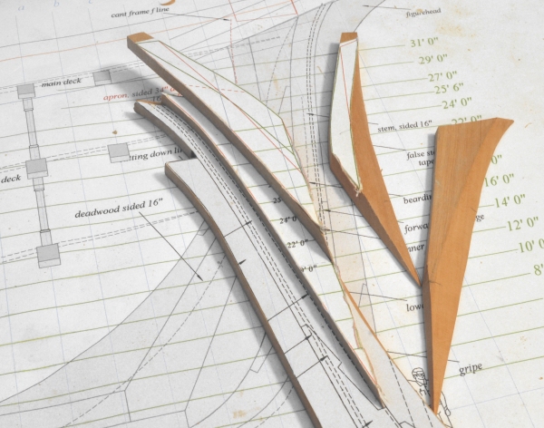
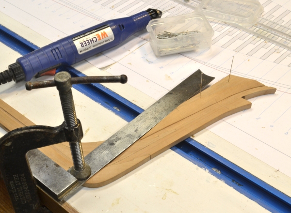
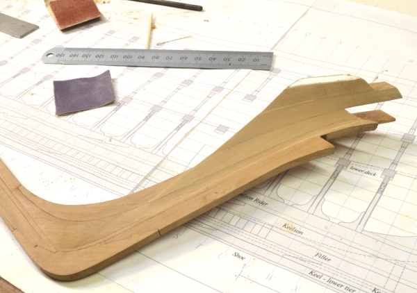
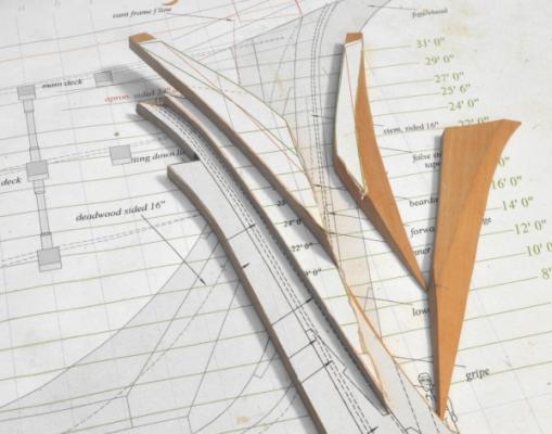
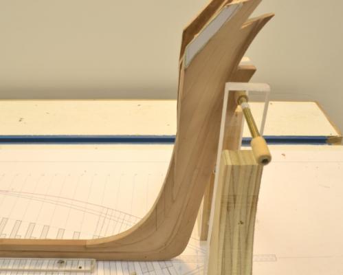
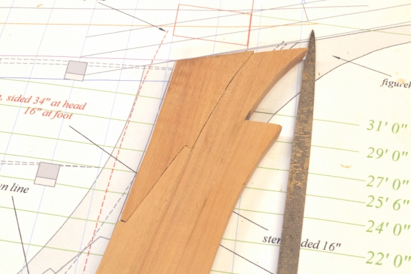
Young America - extreme clipper 1853 Part 11 – Stem Pieces, Knightheads, Hawse Timbers American Clipper Note: The record sailing times logged by American clippers did not result from hull design and huge sail plans alone. The transatlantic packet service, begun in 1818, in which ships advertised - and ran - to a published schedule, placed extreme performance demands on captains and crews. Captains in this trade - many in their 20’s - learned to drive their ships relentlessly, at the expense of ships and men. When the sleek clippers began to come down American shipways, there were captains, well prepared – and still young enough - to make them run. In the last part I mentioned the stem piece fillers on either side of the stem. These pieces, the knightheads, and the first hawse timbers were lofted, cut out and installed as shown below. The first picture shows the stem pieces and knightheads placed in position on the port side, Their starboard counterparts are to the right. These have been pared back almost to the bevel lines on the patterns. (This picture was taken before cutting out the rabbeted area of the pattern as shown in the last part.) In the next picture the stem piece on the starboard side is being pinned in place prior to gluing. The square clamped against the keel in this picture assures that the back face of the stem piece is vertical. It has been beveled on that face to match the first cant frame that will eventually be bolted against it. In the next picture, the last piece – the port hawse piece – is being glued on, completing this stage of the assembly. The next step is to fair these timbers into the stem rabbet. The picture below shows just the preliminary pre-assembly beveling. There is some work to do. Much of the fairing work was done using the curved, flat-faced riffler shown in the next picture. It is a coarse #0 cut Grobet. The smaller riffler in the picture was used in the rabbet corners, Curved scraper blades were also used. The small ruler in the upper right corner of the above picture was used to check the line. The waterlines into the rabbet at this point are almost straight – very slightly convex. Because the initial pieces were cut right to the forward profile, once the glue line is reached the work is finished, except for sanding and leveling out ridges – especially near the rabbet line. The next picture shows the faired assembly. The first cant frame will rest on the beveled back faces of these pieces. The bevels are visible in the next picture. The two vertical pencil lines in the apron show the location of the cant frame pair. The remaining pattern piece in the above photo can be removed. Another hawse timber or two will be bolted to this surface. These will be cut by eye after the cant frames are installed. Ed


- 3,618 replies
-
- 14
-
-
- young america
- clipper
- (and 1 more)
-
HI Tony. Thanks. I am currently thinking it will be rigged, but have not finally decided. Long way to go before that decision needs to be made. Ed
- 3,618 replies
-
- 1
-
-
- young america
- clipper
- (and 1 more)
-
Hi Maury, You are correct. In order for the second pattern to fit accurately the curve of the false stem must be correct. I then have mirrored patterns (thank you CAD) for the forward assembly. I carefully cut along the forward line with a knife and cut horizontally along the keel bottom. The cut patterns are then matched to the forward edge of the false stem. This method is pretty accurate. If the line of the false stem cannot be relied upon, reference lines need to be drawn on the wood to locate the pattern, but I find drawing accurate lines on wood to be a problem, so I avoid it wherever possible - except for rough lines. The one-pixel pattern lines are much more accurate. Ed
- 3,618 replies
-
- 2
-
-
- young america
- clipper
- (and 1 more)
-
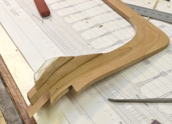
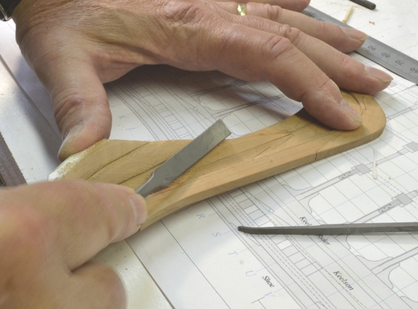
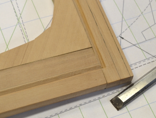
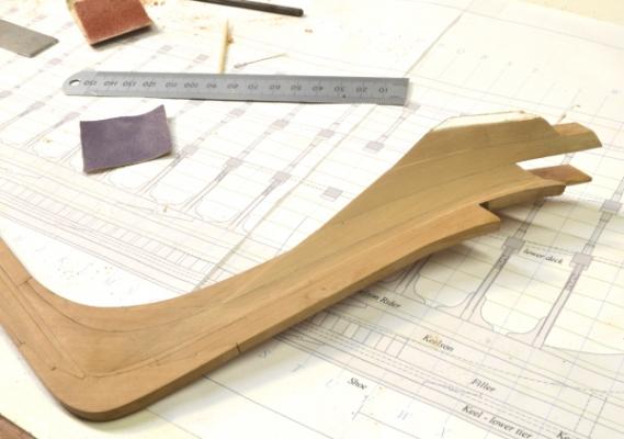
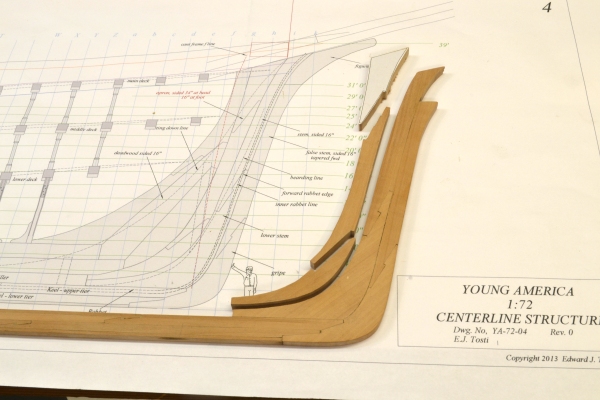
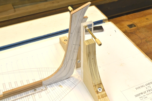
Young America - extreme clipper 1853 Part 10 – Stem – apron and rabbet In an early post, I observed that interest by modelers in American clipper ships seems limited – at least judging by topics on the forum – being hugely eclipsed by interest in 18C RN subjects. I am finding the history of the building, sailing and commercial exploits of these ships extremely fascinating. To throw some light on the subject, I believe I will start inserting some interesting facts in these posts – starting with this one. American Clipper Fact: In December 1850, the extreme clipper John Bertram, 190 feet/1050 tons, was launched at the yard of Ewell and Jackson, East Boston, just 61 days after laying of the keel. She went on to sail for 30 years. (Cutler, Crothers) Back to business. On these ships the apron reinforced the stem and supported the bowsprit. Construction of this member varied, leaving me with another design decision to make. On some ships the apron was cut from a single log. On others it was sided to match the stem and reinforcing “stem pieces” were bolted to either side to make the breadth at the top equal the size of the bowsprit. Young America had a large, 36” diameter bowsprit, so it seemed likely to me that the apron would be of the latter type, so that is the design I used. It is a subtle difference on the model – perhaps not even visible. This allowed me to proceed with the apron – sided 16”. The first picture shows the three pieces of the apron during fitting. The next picture shows the central piece being glued on. This was done after the lower section had been installed – working up from the bottom. The next picture shows the top piece – fit-up, but not yet glued. In the next picture the apron is secured. The filler piece behind it on the keel is also installed. Mirrored patterns of the assembly have been pasted to both sides in this picture so the stem rabbet can be accurately marked out. In the next picture the rabbeted area has been removed from the starboard pattern and the line of the inside of the rabbet is being deepened with a hobby knife. The rabbet widens toward the bottom. Technically, it extends from its forward line to the bearding line – the line defined by the top cut on the pattern. Both these lines were constructed on the drawings from the intersection of the waterlines with the inner rabbet and the side of the apron respectively. The forward rabbet line was constructed from the intersections at the forward end of the planks. The rabbet is very wide at the bottom because of the extremely sharp entry of the forward hull lines. In the next picture the rabbet is being enlarged with a full-sized V-gouge after the center line was cut with a smaller tool of the same type. The smaller gouge is to the right in the next picture, which shows the wide part of the rabbet being pared back with a straight chisel. The front part of the pattern was removed to better see the forward edge of the groove. This paring is only partially done at this stage. Further shaping will be done after the stem pieces and knightheads are installed. The last picture shows the assembly set up on the board after rabbets were cut on both sides. I believe the next step will be the fitting of the stem pieces and knightheads – after some lofting of these highly curved and beveled pieces. Ed
- 3,618 replies
-
- 15
-
-
- young america
- clipper
- (and 1 more)
-
Thank you all for these comments - an for the "likes". I wish progress were a bit faster. Sherry, I can take little credit for the adjustable supports. Many on the forum have used them - Gary, Keith to name just a couple. I think they will be worth a try for you. On YA it will be a challnge - with her long hull - to keep her square. John, I hope I can do her justice. the more I read about these ships, the more impressive they become. YA is quite different from Naiad - offering new challenges and alot of different details. I spent a good part of yesterday lofting the sweeping knightheads and stempieces - fun. Rob, whenever you post, with that profile picture of McKay, I feel that the old master is looking over my shoulder. Perhaps he is thinking, "Webb! He's building another one!" Ed
- 3,618 replies
-
- 2
-
-
- young america
- clipper
- (and 1 more)
-
Toni, You have my sympathy with the brass bolts. Brass doesn't like to get black or stay black - paint or selenious solution - doesn't matter. Rub your finger over it and you will likely create a bright spot. Facing thousands of bolts on Naiad, I rejected brass. Perhaps the following will be helpful. A one-half inch thick round bolt head at 1/48 scale will only project 10-thousandths of an inch. That bump is just about detectable. If driven home into wood the projection is probably less than half that - even with a washer. I adopted two alternate materials for bolts. For iron driven into wood, I genrally used black monofilament fishing line dipped in CA. Fidhing line was suggested to me by the late Alexei Romashenko. This can be cut off flush or slightly above the surface. In the latter case a few passes with 320-grit paper will round the head a bit. For bolts driven through ironwork, I used copper wire, forced home into the underlying wood, then cut off just above the surface. Tapping with a hammer peens it over and rounds it off somewhat. It can then be blackened with no effect on surrounding wood using liver of sulfur solution. LOS does not work on brass. The only place I left monofilament bolts protrude was on the globe-headed type used to secure the ribbands to the frames. I sanded these to round them a bit. At 1:60 I made all bolts in wood essentially flush. I have not had much luck with cup burs. Maybe its the copper. They clog with soft materials. Remco recently suggested a new type that resists clogging. Here's a link: http://www.gesswein.com/p-10767-busch-burs-twin-cut-cup-fig-411t.aspx I have not tried these. Hope this is helpful. Ed
-
ancre LE BONHOMME RICHARD by Jeronimo - FINISHED
EdT replied to Jeronimo's topic in - Build logs for subjects built 1751 - 1800
Beautiful work, as always, Karl. Ed- 662 replies
-
- 1
-
-
- bonhomme richard
- frigate
- (and 1 more)
-
Thank you, Patrick. I am glad you find these "how to" overviews interesting. Unfortunately, in this format they are pretty sketchy and not fully descriptive. The hull will be about 42" long - a large model by my standards - small relative to some others on MSW. Rigged - if I go that far - it will be quite large. Ed
- 3,618 replies
-
- 2
-
-
- young america
- clipper
- (and 1 more)
-
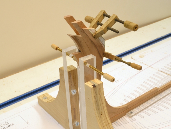
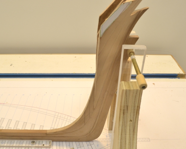
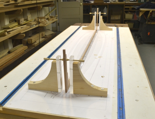
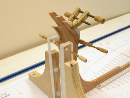
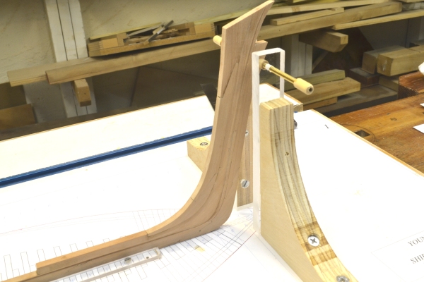
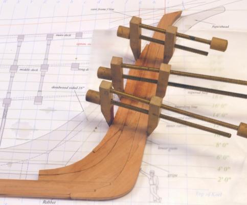
Young America - extreme clipper 1853 Part 9 – Sternpost Rabbet – Shipway Fixtures Progress continues – if slowly. A lot of drawing checking and refining of the lines at the stem has taken some time – final adjustments to the waterline intersections to the stem and consequent re-plotting of the rabbet and bearding lines. I learned from Naiad that its best to get all this correct at the start. In the first picture the straight rabbet on the sternpost is being formed with the scraper used on the keel, but with a holder to set it at the correct line for the post. The intersections of the keel and sternpost rabbets were the cut with a v-gouge. The corners were then trimmed with a straight paring chisel. The area of the deadwood within the rabbet will eventually be pared out. I would prefer to do some of this work at this stage up to the bearding line while the piece can be laid flat, but unfortunately most of the deadwood is installed over the keelsons in these ships and they cannot be installed until the aft frames are set. They next picture shows the last piece at the stern that can be installed before the frames – this is a filler over the keel between the last square frame and the stern knee. Some of the aforementioned bearding line is just visible on the drawing in this picture, just above the center of the knee. Before going much further, the shipway needed to be fitted with fixtures to hold and align the keel assembly. In the spirit of continuous improvement, these are different from those used on Naiad. In the first picture a Plexiglas strip is being screwed down to hold the starboard side of the keel. Plexiglas has the advantage of transparency, but it is flexible, so it is being aligned against the straightedge. The second strip was aligned using the keel and is being screwed down in the next picture. The lateral supports for the stem and sternpost are also different. They are made to allow screw adjustment of the vertical position. A good idea I picked up from other posts on the forum. The 6-32 rods are screwed through holes tapped in 3/8" thick Plexiglas. These end supports will eventually be in the way and will need to be replaced with something else, but that is a long way off and these should work well to keep the hull aligned during framing. In the next part I will discuss some design issues that needed to be resolved on the stem before installing the apron. I am beginning to feel that the erection of the midship frame bend is not far off. Ed


- 3,618 replies
-
- 13
-
-
- young america
- clipper
- (and 1 more)
-
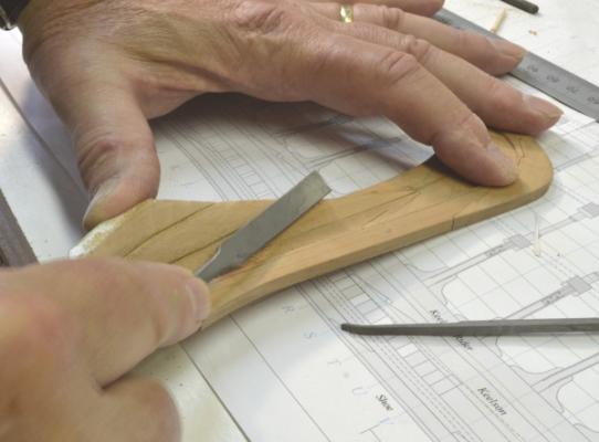
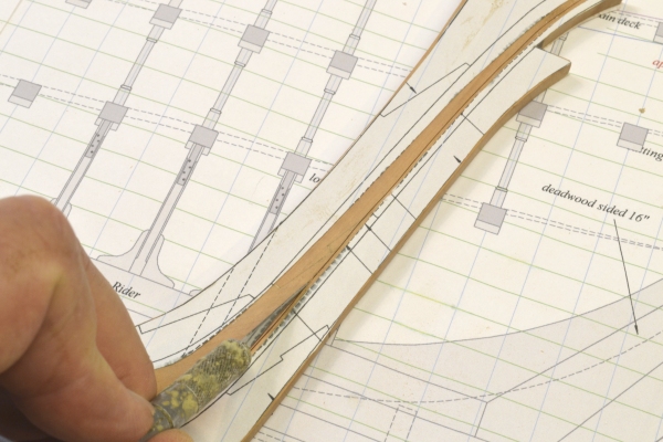
Young America - extreme clipper 1853 Part 8 – Sternpost A week’s vacation and some additional necessary research have interrupted the construction work. The beach at Cape May, New Jersey faces south, looking out across the mouth of the Delaware Bay. It was interesting to contemplate Young America traversing that stretch of water on her last cruise in 1886. Victorian bathers on this beach may have been the last people to see her. My family was – not too surprisingly - unimpressed with this observation. Before proceeding with the sternpost, I needed to do some additional drafting to confirm the correct height of this and the inner post. This required some speculation on the framing of her circular stern. Some of these decisions are subtle, but need to be made. I finally decided to go with a transomless stern. This will be covered much later – after the aft cant framing. The first picture shows the sternpost and inner post cut out based on the latest patterns. The sternpost is 18” wide at the top – tapering to the 16” wide keel breadth at the bottom – same for the inner post. The aft face of the sternpost is beveled at 21 degrees on each side with the plane of the angles passing through the centers of the pintle bearings. I bearded this angle using the tilting table of the disk sander set at 21 degrees –bringing the bevels to a point on the centerline of the post. The first sanding step is shown in the next picture. The aft face was then planed back to leave room for the pintles with the outside corners appropriately beveled. The final siding of the post (fore and aft) was then sized on the circular saw. The post was then tapered slightly – and very carefully - on both sides to keel breadth at the bottom on the belt sander as shown below. After forming a tenon on the bottom of the post, the mortise for it in the keel was then cut as shown below using a small mortise chisel. The pieces were then fit. The next picture shows the joint during this process. The post rakes aft at a slight angle. I left the post slightly over-length at this stage. The next picture shows the post temporarily fitted. The inner post was then jointed in the same way. The keel is still slightly over-length at this stage. After the posts were fit, the large sternpost knee was cut out, fitted and glued to the keel. Installing this knee first assures that the sternpost will be raked at the correct angle. The two posts were next glued together, then glued to the knee and the keel as shown below. The next step will be to finish the sides, cut the rabbets on the sternpost and join it to the rabbet on the keel. Ed


- 3,618 replies
-
- 14
-
-
- young america
- clipper
- (and 1 more)
-
Thank you, Greg. Your comments are well appreciated. Ed
-
HMS Sussex by mij - Scale 1:48
EdT replied to mij's topic in - Build logs for subjects built 1501 - 1750
Impressive tool collection, mij. I will add a few thoughts about the spindle sander. It is a very useful tool for sanding the insides of curves. I would recommend an oscillating type to avoid sanding the same spot on the drums and one with multiple drum diameters. A would also highly recommend some sort of dust collection on this and all power sanders. This can be as simple as a shop vacuum connected to the sander and run off a combined switch. Before dust collection my sanding spread dust from the basement throughout the house and I woke up most mornings with congestion - no more. Before buying a spindle sander I used a drum fitted to a table top drill press. All the frames on Naiad were done with this arrangment. Ed -
HMS Sussex by mij - Scale 1:48
EdT replied to mij's topic in - Build logs for subjects built 1501 - 1750
God start Mij. I look forward to following your progress. Ed -
Gd to see your new potings, Gary. Great work as usual. Ed
-
There is a simple cure for unhapiness at finishing the Aubrey/Maturin saga. Start over. Ed
-
Rob, with regard to your question on Young America's poop deck, Crothers plans show a 44 foot long poop at the level of the fancy rail with two skylights aft of the mizzen. This is also shown on p. 416 of his book. There are 4 references listed for this diagram - the original offsets (which may not be relevant to the poop itself), the two photos and Howe and Matthews, American Clipper Ships 1833-1858, orig pub 1926-1927. The photo from the starboard quarter shows men standing at the level of the fancy rail on the poop. I posted this photo in Part 1. Howe and Matthews say she had a 42' long poor deck. On his plans, Crothers has made this 44' (I believe correctly), probably because there is no supporting deck beam for the poop bulkhead at 42'. Below the poop there is an intermediate deck that is stepped down from the main deck, which is at the level of the planksheer. The fancy rail runs generally about 4 feet above the planksheer. I cannot discern any definitive poop detail from the images I have of some paintings. Lacking anything more definitive than the photos, Howe and Matthews writeup and Crothers work, I expect to follow his interpretation. Except for setting out the deck heights on the various sheer views, I have made no drawings, as yet, of these deck details. Ed
- 3,618 replies
-
- 1
-
-
- young america
- clipper
- (and 1 more)
-
Thank you, Micheal Guy and Menno. Still away, so no work is going on this week. Ed
- 3,618 replies
-
- 1
-
-
- young america
- clipper
- (and 1 more)
-
HMS Naiad 1797 by albert - FINISHED - 1/48
EdT replied to albert's topic in - Build logs for subjects built 1751 - 1800
Albert, one other thing - I know it is dificult to provide English text with your pictures, but I am sure everyone would be interested in descriptions. Perhaps you can use Google translate to give English translations. I know this will add work to your postings, but your initial progress promises to yield a very beautiful model and I can assure you that many - I for sure - would like to read your descriptions of the work. Just a suggestion. Ed -
HMS Naiad 1797 by albert - FINISHED - 1/48
EdT replied to albert's topic in - Build logs for subjects built 1751 - 1800
Albert, Very nice work on the shipway, the gantry and the clamped squares. I trust they will serve you well in the work ahaead. I join the others in marvelling at the neatness of your workspace. Again, good luck with the build. Ed