pirozzi
-
Posts
843 -
Joined
-
Last visited
Content Type
Profiles
Forums
Gallery
Events
Everything posted by pirozzi
-
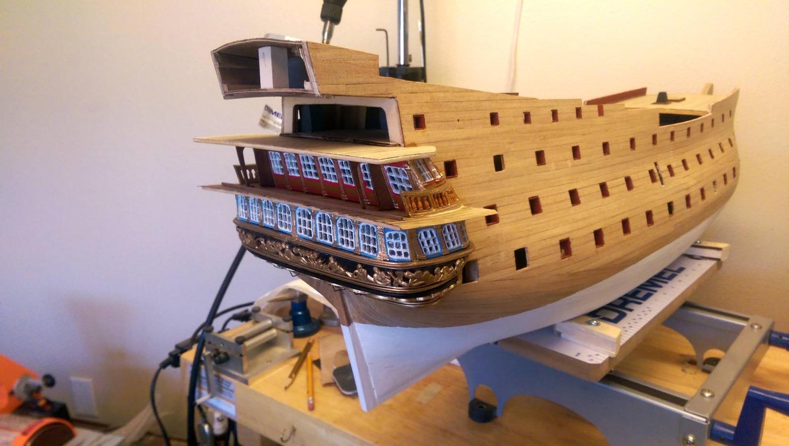
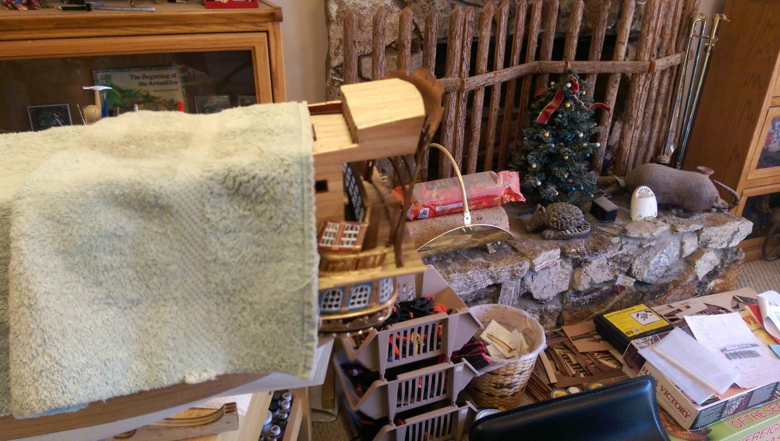
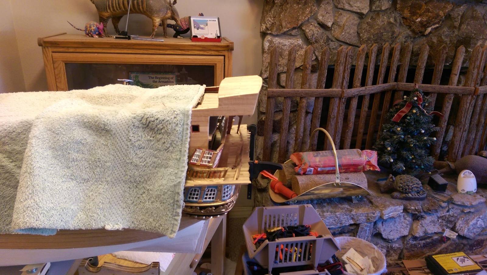
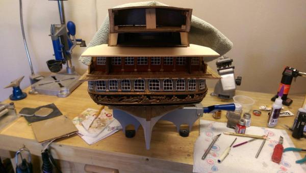
 The gallery quarterdeck extension is in place. It will be trimmed and beveled to fit the transom. Vince P.
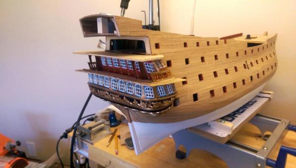
- 593 replies
-
- 2
-

-
- royal william
- euromodels
- (and 1 more)
-
Hi Gary, In defense of Euromodels, I don't fault them for the problems I am having. Yes, the kit is very expensive, mostly because of the numerous metal castings and materials. This kit however is so much like a scratch build that very little is defined in instructions and drawings as is with most kits. The plans are really excellent and if the builder uses them very carefully before making any complex moves with the build, it should turnout OK. The problems I am having is that I was spoiled with other kits like the SOS, which had more detailed instructions, even though they were flawed. This kit requires the builder to really have a scratch build mentality, which is new to me. As I gain more experience here it is becoming easier to progress. I can't emphasize enough that this kit is an extremely difficult and challenging project. I thought I was a pretty advanced builder until I started this. I have made some mistakes and had to cover them up, but the more I work on this, the more confident I have become. It is so challenging that I find it difficult to walk away from the work bench. I have found myself waking up from a sound sleep with a solution to something that was bugging me during the day. So I either wrote it down, or went to the work bench at 4 in the morning to try it. This is so much fun! I do warn anybody thinking of building this kit to give it a long thought, but it is the best project I have started to date. Vince P.
- 593 replies
-
- 8
-
-
- royal william
- euromodels
- (and 1 more)
-
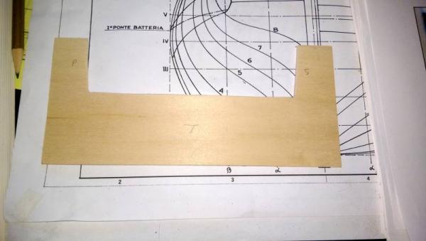
Working on the next gallery deck up. I cut a piece of plywood like before for the deck (not supplied). It will be planked, stained, and trimmed before it is installed. Vince P.
- 593 replies
-
- 7
-
-
- royal william
- euromodels
- (and 1 more)
-
Hi Greg, We have a big house and the admiral allowed me to convert the living room with the pool table in it to my workshop. Yes, dust is a problem, but as long as I keep it all in that room I won't walk the plank. Vince P.
- 593 replies
-
- 3
-
-
- royal william
- euromodels
- (and 1 more)
-
OK, the pot did the trick. The transom piece retained the curve needed to wrap it around the end of the decks. I placed the transom piece without gluing, just to see how it fits. It fits very well and will be easy to secure properly once I get to that point. I still have to create the upper deck gallery windows and place them before the transom piece. The transom piece will also need to be planked on both sides. Vince P.


- 593 replies
-
- 9
-
-
- royal william
- euromodels
- (and 1 more)
-
Hi Greg, I think it will be a little more than needed. With the curve in place I can then just place it on the deck ends and clamp it to the exact curve needed. There will be just a slight adjustment and no fear of it breaking. I picked a cooking pot big enough to approximate the curve needed. Vince P.
- 593 replies
-
- 3
-
-
- royal william
- euromodels
- (and 1 more)
-
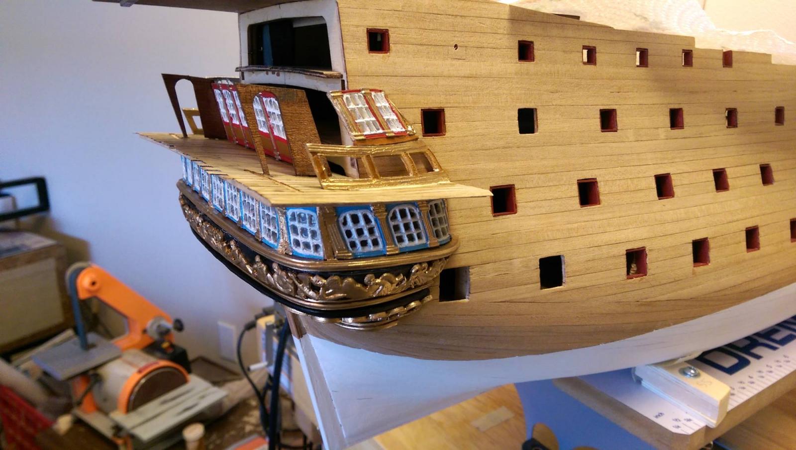
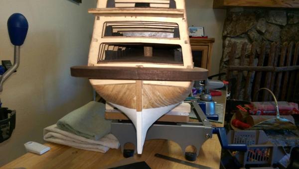
Before placing the transom piece, an aligment needs to be made with all of the gallery deck ends. It became apparent that the poop deck extends out too far. I needed to trim it off considerably and relocate it. I knew I would have to make some adjustment, just not that much. In retrospect, if I had to do it over, I would not have placed the poop deck at all until the transom was in place. I seem to remember one of our experienced builders on this forum pointed that out to me. You live and learn. The photos show it trimmed and positioned correctly to receive the transom. Vince P.

- 593 replies
-
- 6
-
-
- royal william
- euromodels
- (and 1 more)
-
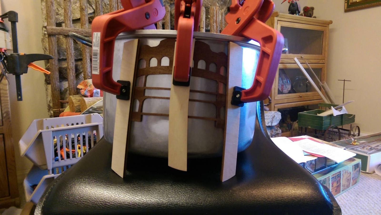
The transom piece needs to be bent to follow the deck contours. It is made of thin plywood and very brittle. It would most certainly break if pushed to meet the needed curve. I soaked it in an ammonia solution like I used for planking and then got the bright idea to use one of the Admiral's big cooking pots. I slowly bent it around the outside of the pot when it got soft and clamped it in place. I then used a hair dryer on high heat to dry it off. It is still there. I will remove it and see what curve it maintains. It didn't break though. Vince P.

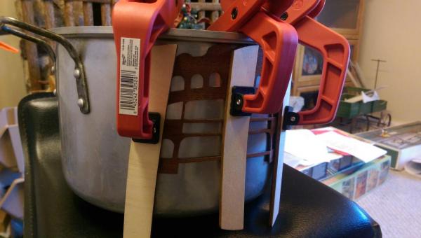
- 593 replies
-
- 6
-
-
- royal william
- euromodels
- (and 1 more)
-
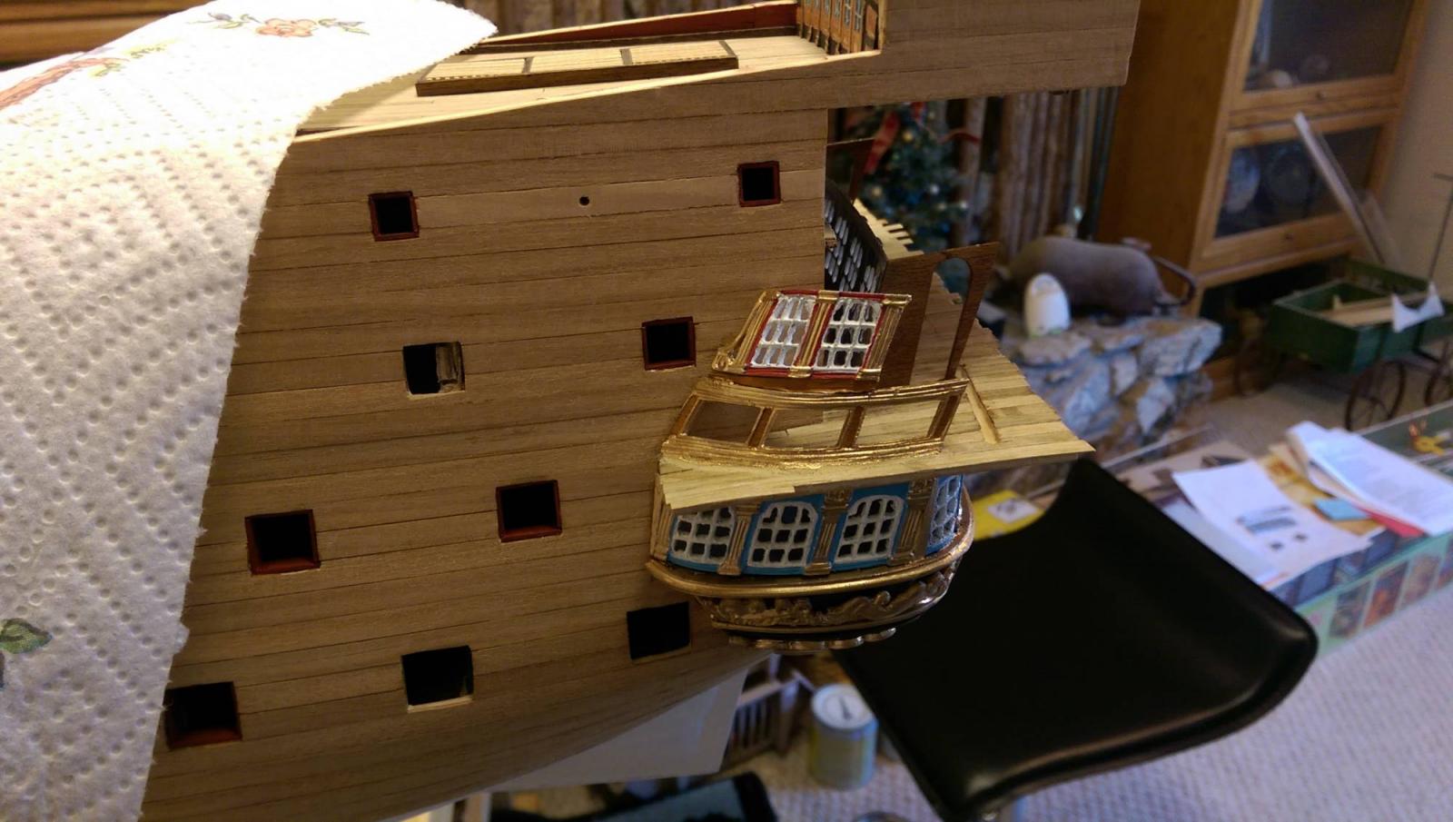
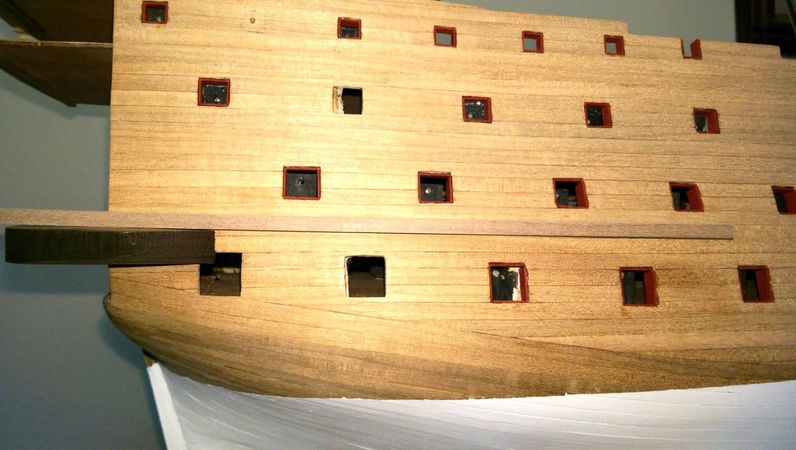
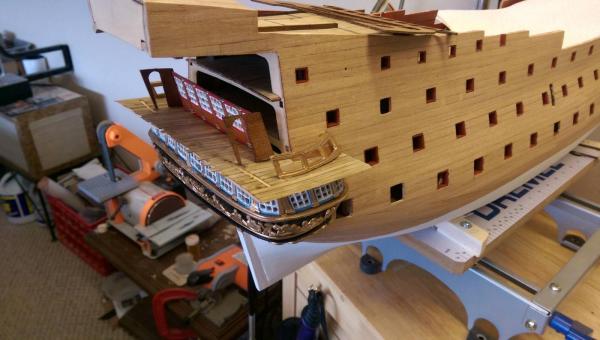
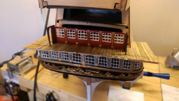
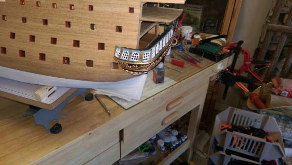
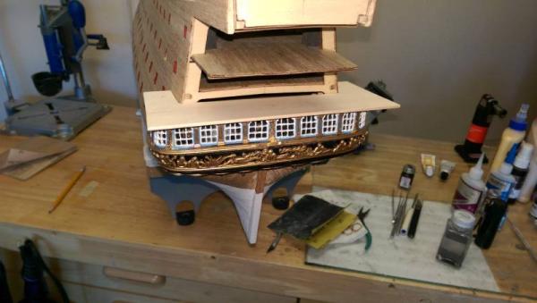
The 2 outside windows for the middle stern gallery are in place. These took considerable trimming and shaping to fit correctly. Vince P.

- 593 replies
-
- 6
-
-
- royal william
- euromodels
- (and 1 more)
-
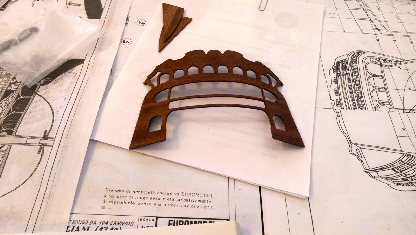
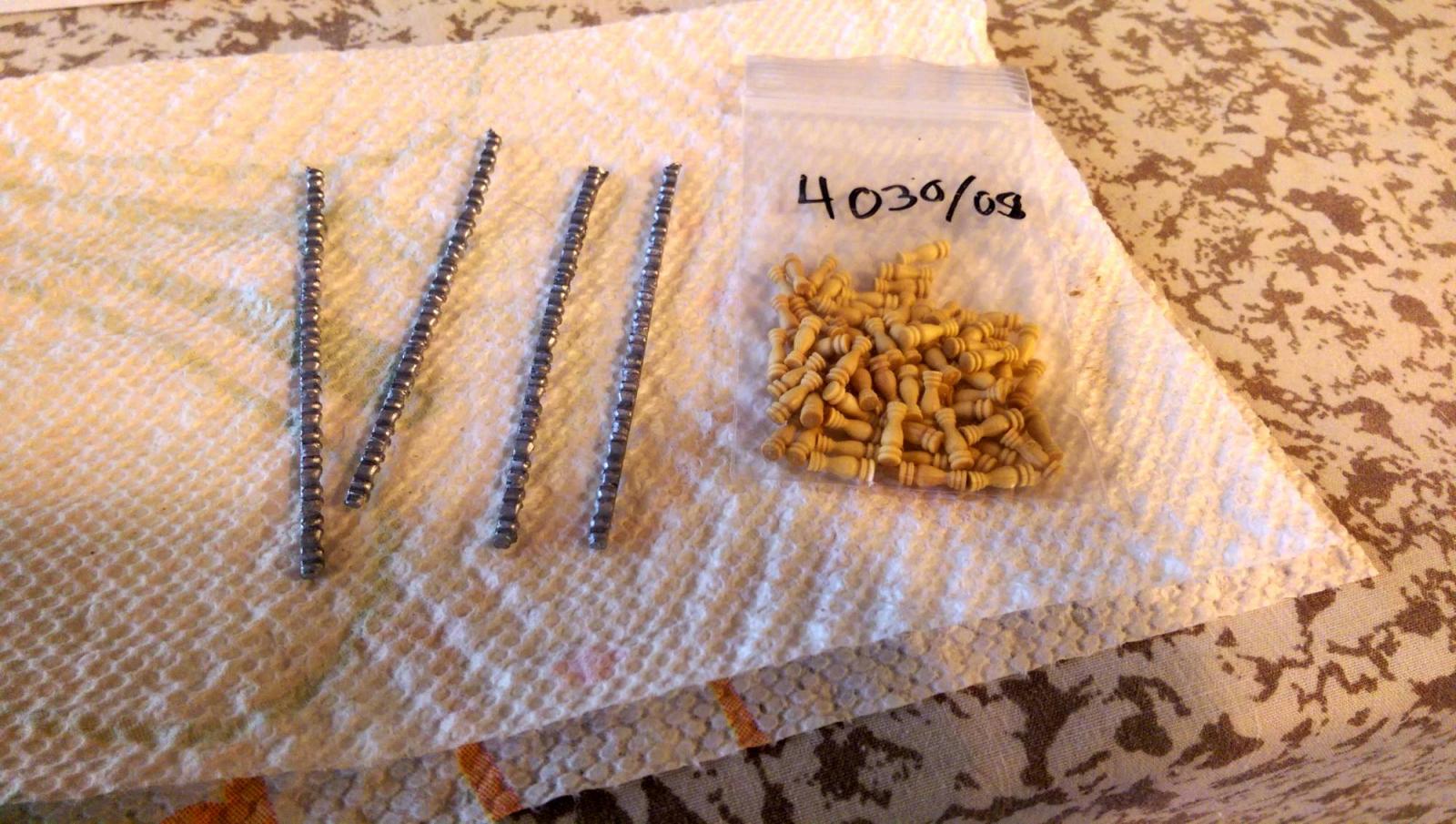
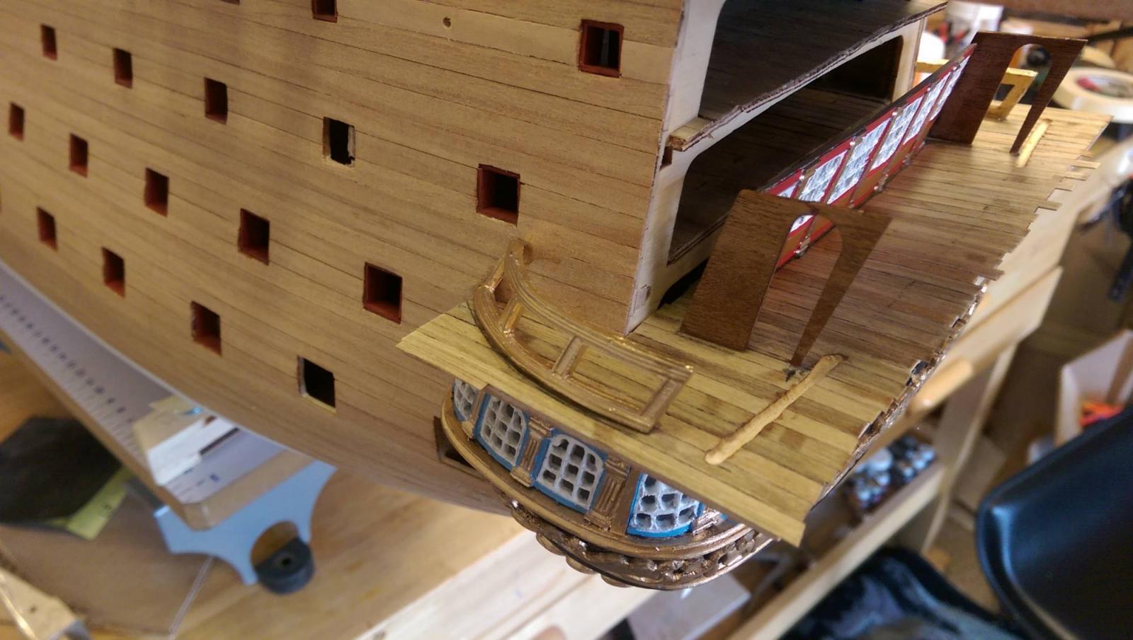
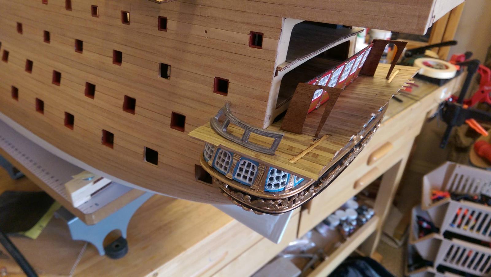
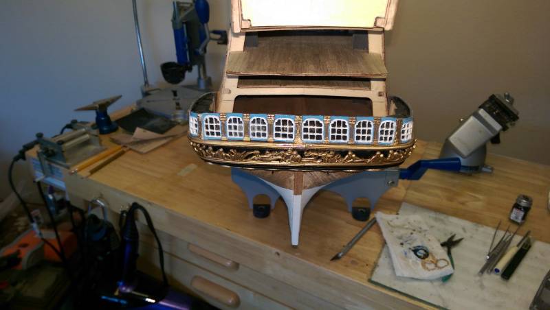
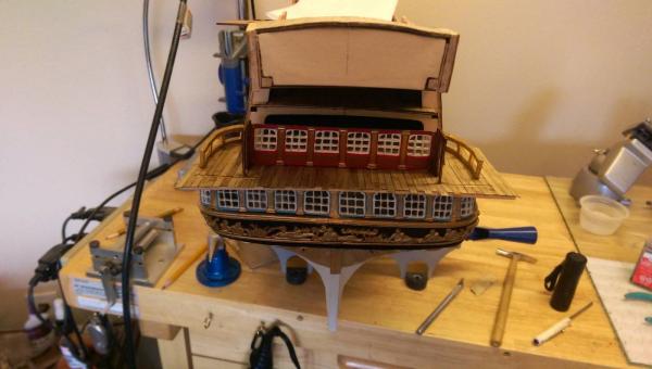
The bannisters for the railing had to be added. The kit provides metal decorative strips that must be cut to form stanchions, and they are ok, but I decided to use carved wood stanchions instead. I think they look better. These were 8mm made of boxwood from my stash. I painted them a medium brown. Vince P.


- 593 replies
-
- 7
-
-
- royal william
- euromodels
- (and 1 more)
-
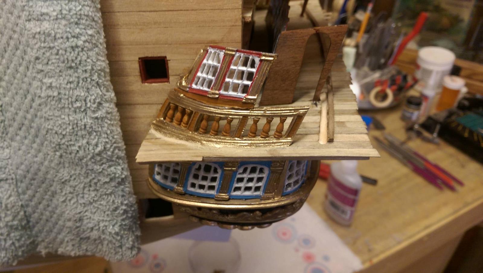
The outside windows for the middle deck are added on top of the end railings. These also needed to be bent and formed considerably using a torch. Vince P.


- 593 replies
-
- 5
-
-
- royal william
- euromodels
- (and 1 more)
-
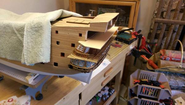
Still working on building up the transom. It is very slow tedious work. Every single piece has to be custom fit and there are no clear plans or dimensions to work with. And, as antcipated, nothing fits correctly. I am relying heavily on photos of completed models on the Euro and other websites for some inclination on how this is supposed to look. Pete's reference notes and Julier's build log are also helpful here. It seems that every piece relies on all of the other pieces to fit together. This requires placing other pieces temporarily to fit each piece as you go. If you miss considering just fitting one piece, you could wind up with a piece later on not fitting at all which requires removing other pieces and readjusting. This has happen to me and is a real nightmare. These photos show the middle deck railing ends. The railing is actually 4 pieces and the 2 end ones must be mounted first. The 2 middle pieces can not be added until the transom back is installed later on. Vince P.
- 593 replies
-
- 5
-
-
- royal william
- euromodels
- (and 1 more)
-
Hi Greg, I had not thought about putting lights in her. I just did not like the metal windows in the kit and decided to cut them out and use a window film to make the glass panes look realistic. Vince P.
- 593 replies
-
- 2
-
-
- royal william
- euromodels
- (and 1 more)
-
The side railings for the middle gallery deck must be contoured significantly as well as filed in order to follow the gallery curves. Once again, a small torch and very careful hammering was needed to do this without breaking them. The last 2 photos show them before and after reshaping. Vince P.
- 593 replies
-
- 6
-
-
- royal william
- euromodels
- (and 1 more)
-
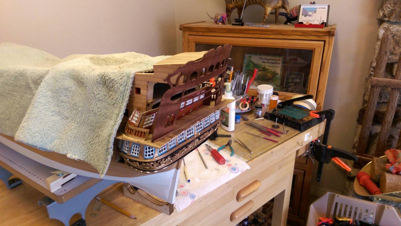
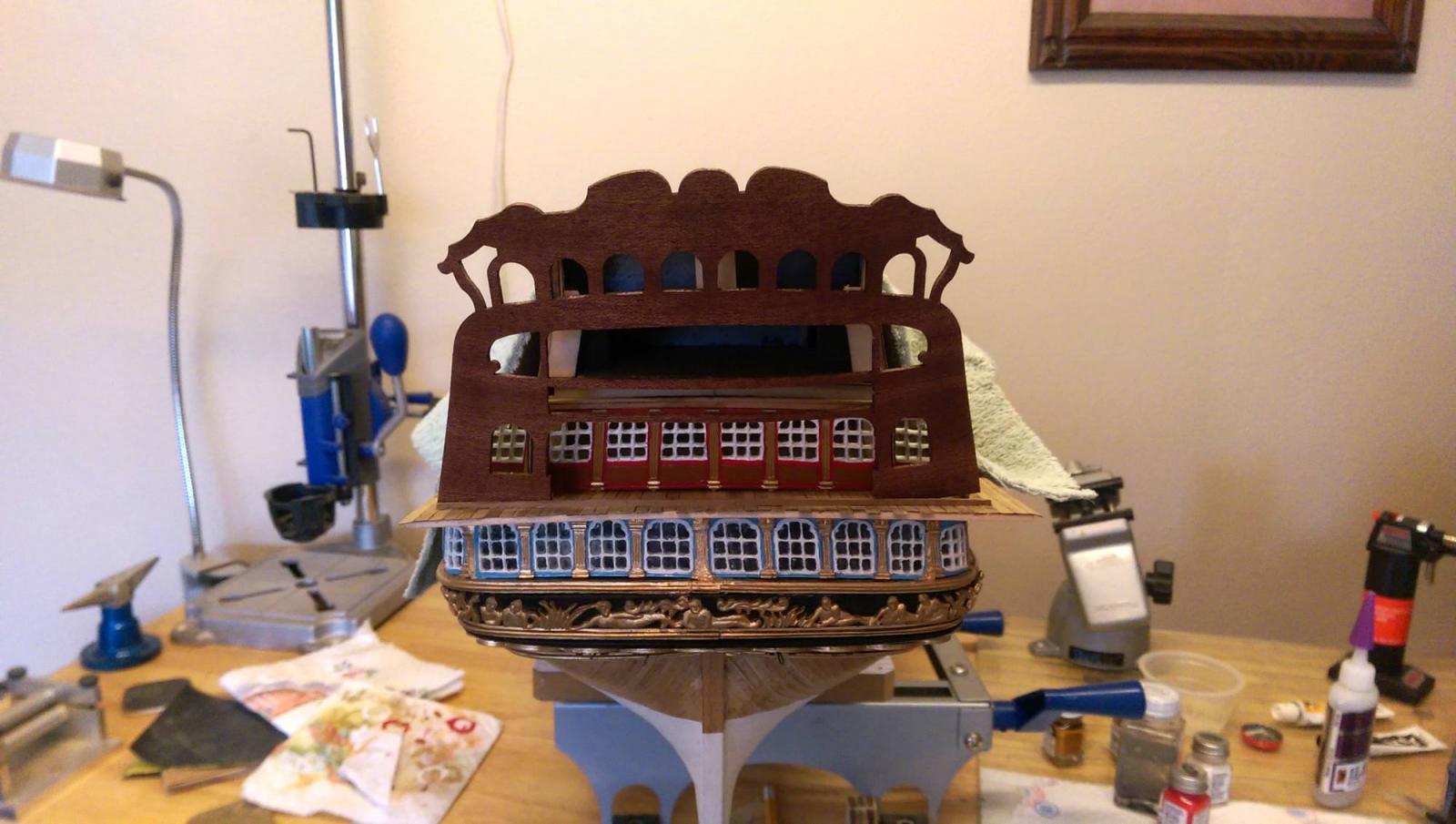
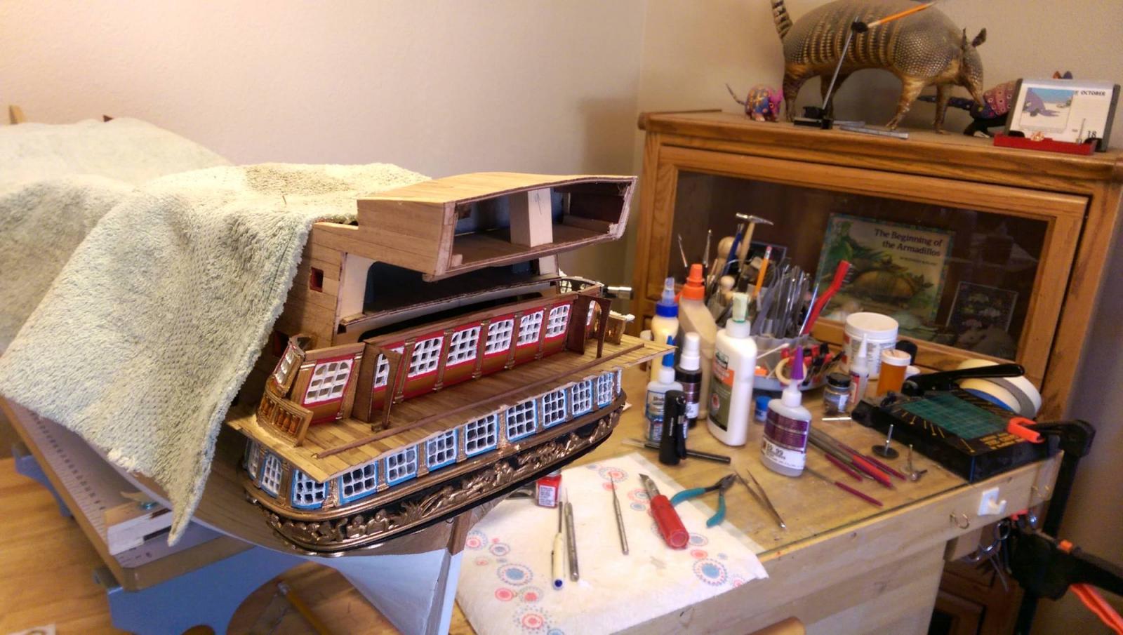
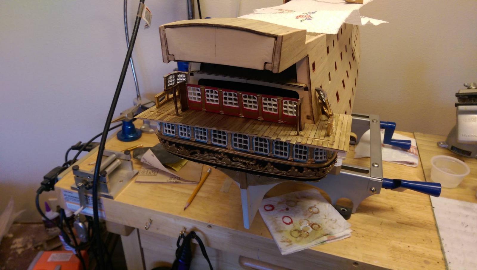
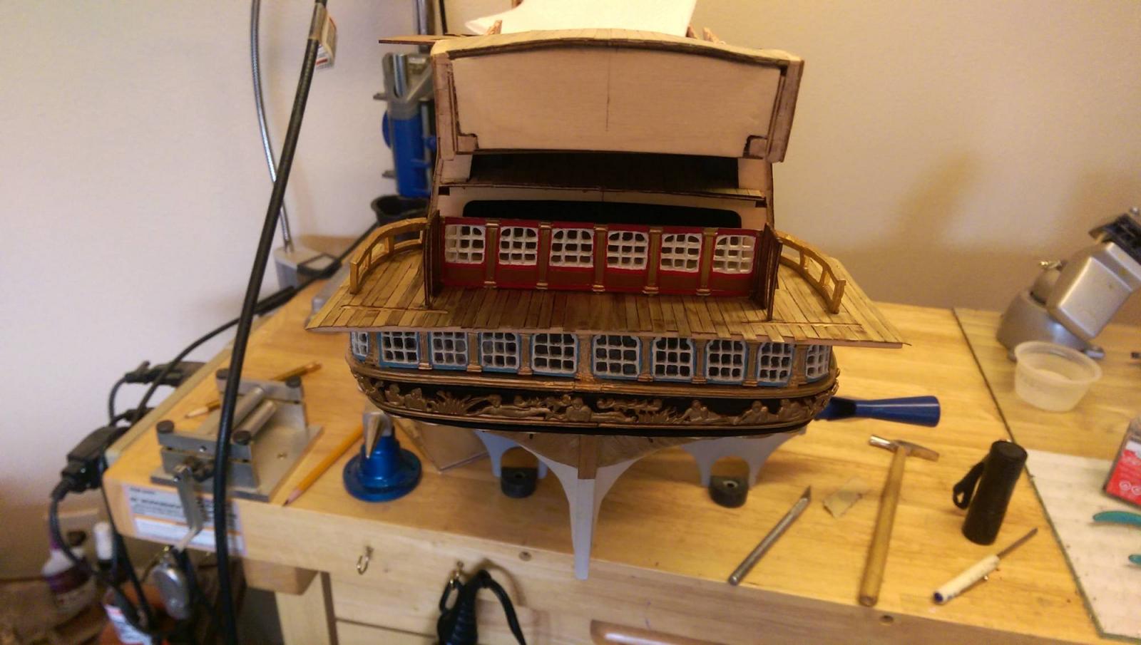
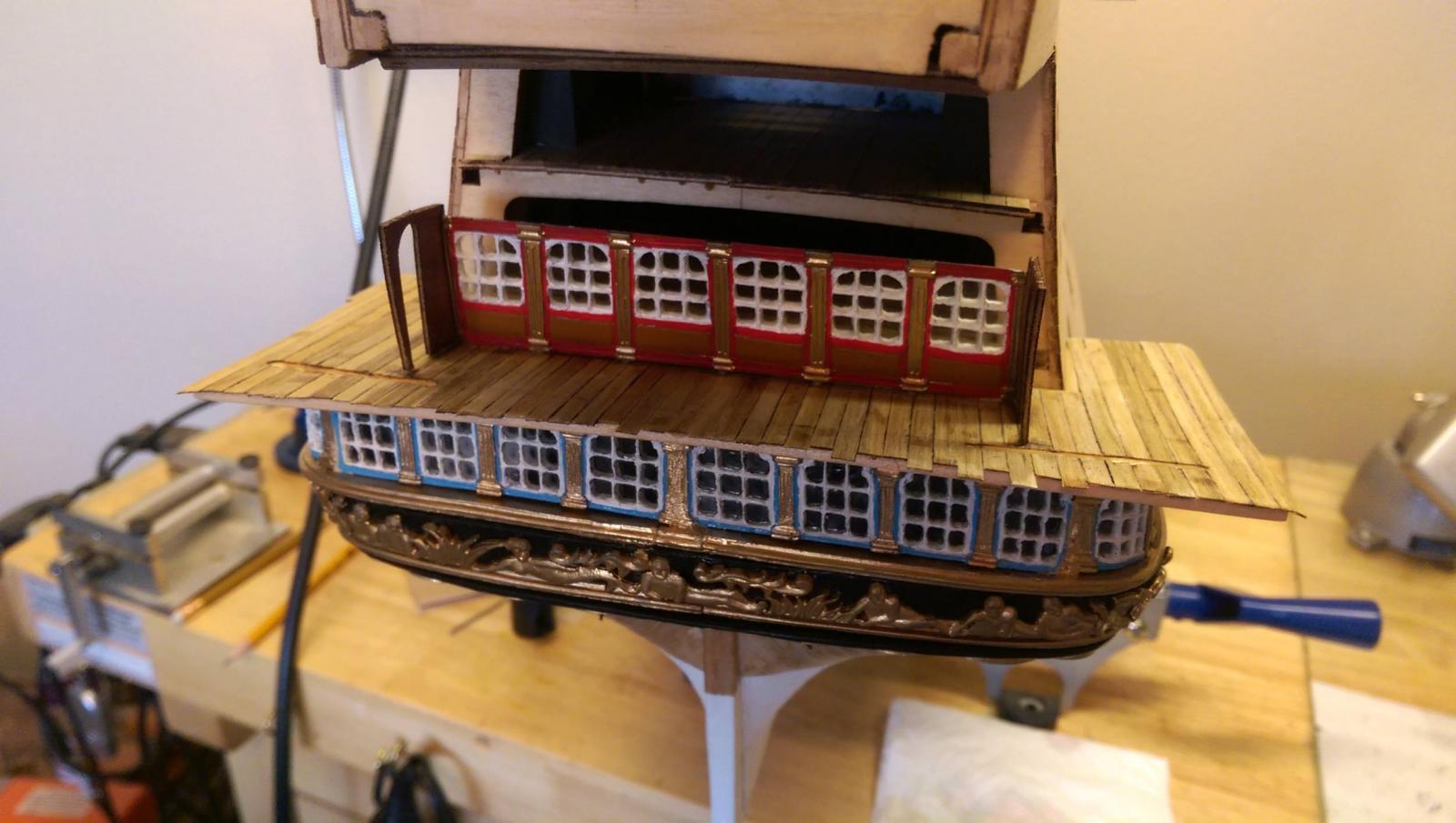
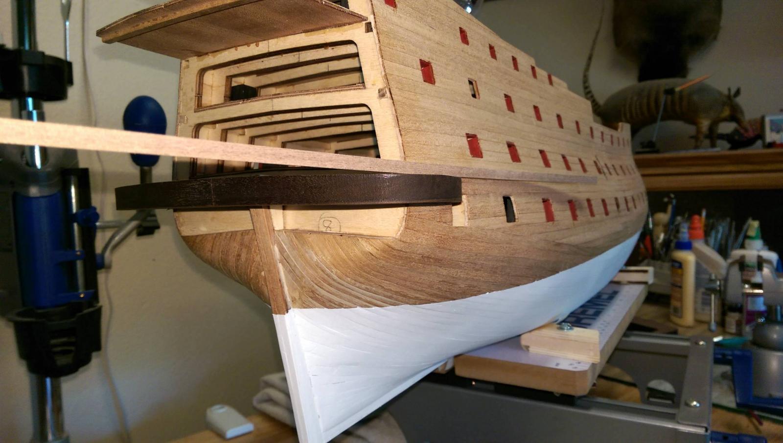
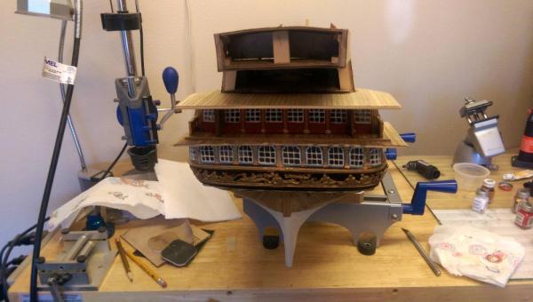
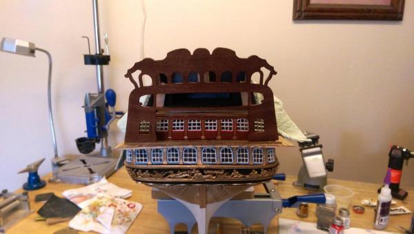
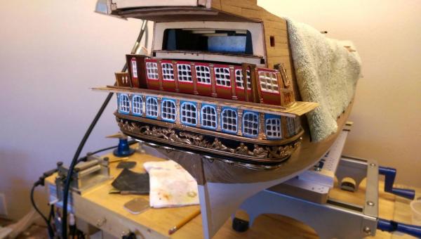
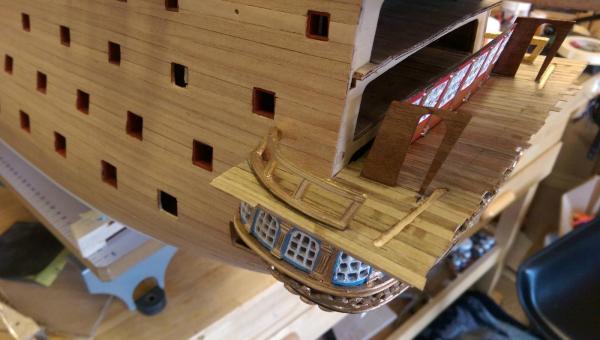
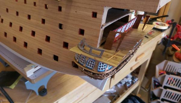
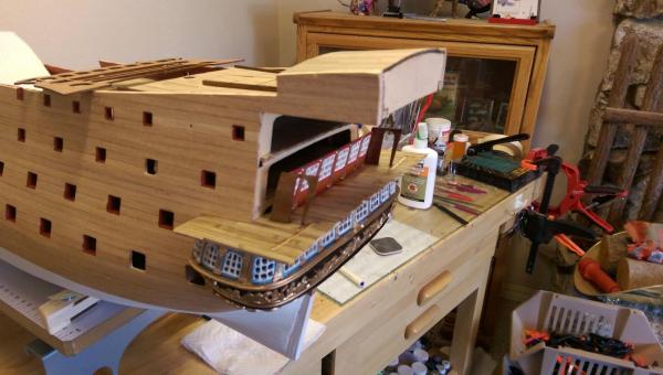
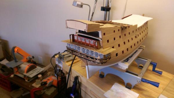
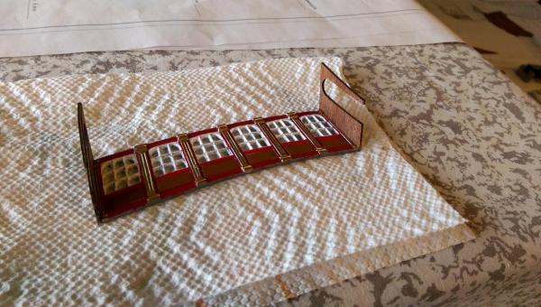
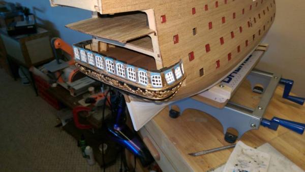
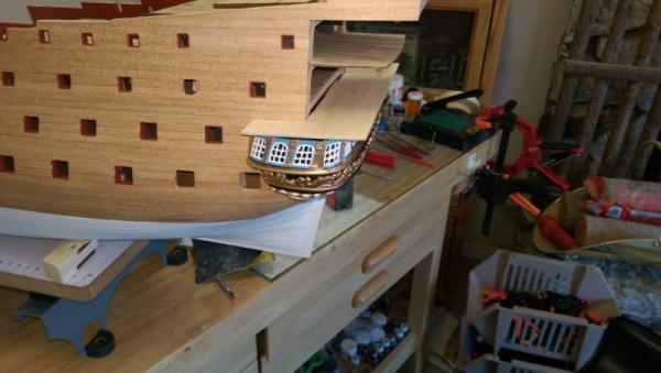
The middle gallery deck has been planked and the window section has been mounted. Two slots are cut in to the deck to take the bottom of the transom backing, which will be placed after the upper deck and windows are installed. Next up will be to continue the middle gallery windows around to the hull sides and install the ballestrade railing around the edge of the decking. Once that is done, the deck will be trimmed back to the curve of the stern and a trim added to this edge. Vince P.
- 593 replies
-
- 11
-
-
- royal william
- euromodels
- (and 1 more)
-
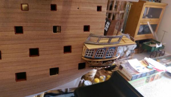
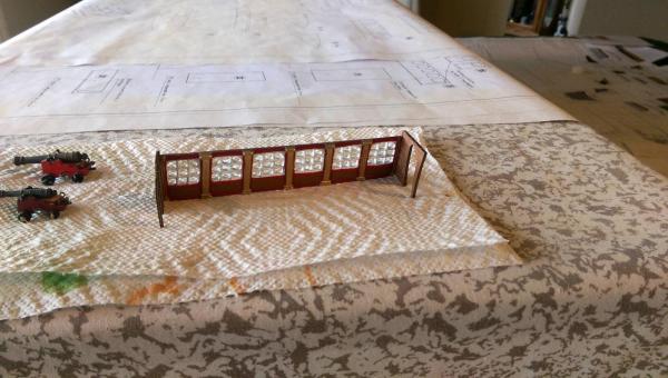
The middle gallery windows are ready for the window glass. These windows are the first set which are recessed on the transom. Locating where to place these is critical to the placement of the actual transom, which butts up against to 2 outer doorway panels on the ends of these windows. The plans are not much help here at all. Vince P.
- 593 replies
-
- 5
-
-
- royal william
- euromodels
- (and 1 more)
-
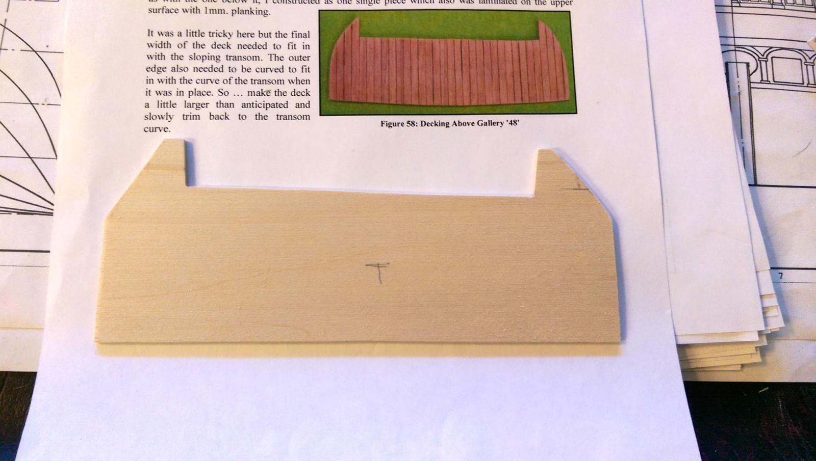
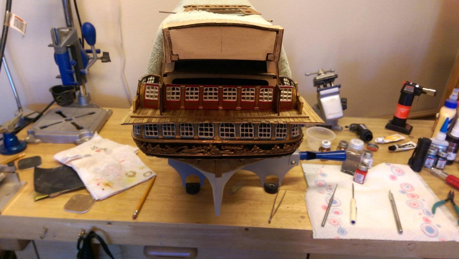
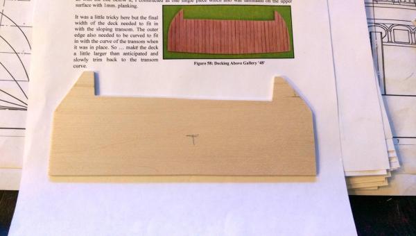
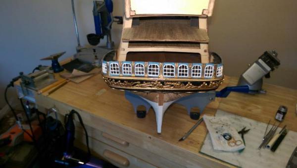
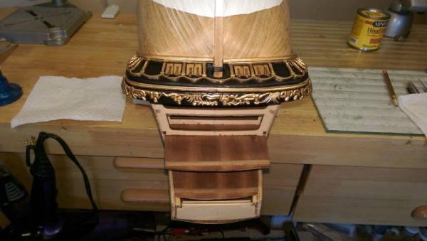
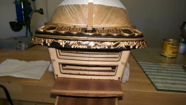
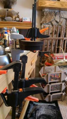
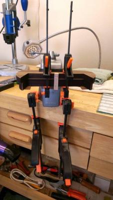
Continuing on with the stern galleries and transom. 1. The upper metal trim piece is placed on the transom base. 2. The lower gallery windows which consist of 6 pieces are put in place. They had to be bent and contoured considerably using a butane torch. A number of backing plates made up of scrap wood were glued to the base and painted black. These are needed to support the metal window pieces. There were some gaps in the window pieces which had to be filled in with a filler. 3. The extended deck which mounts on top of the lower gallery windows was made from a sheet of 3/32" x 4" x 24" basswood (not included). The width from the frame 8 to the deck end needs to be 48mm to allow enough overhang from the windows to support the transom back and also the stanchion railing. Once placed permantely, it will be cut to match the contour of the stern galleries. It will also then be planked on top with deck planking strips.

- 593 replies
-
- 10
-
-
- royal william
- euromodels
- (and 1 more)
-
Good idea JP. I will try to glue them back on with epoxy. Will let you know how it turns out. Thanks, Vince P.
- 593 replies
-
- 1
-
-
- royal william
- euromodels
- (and 1 more)
-
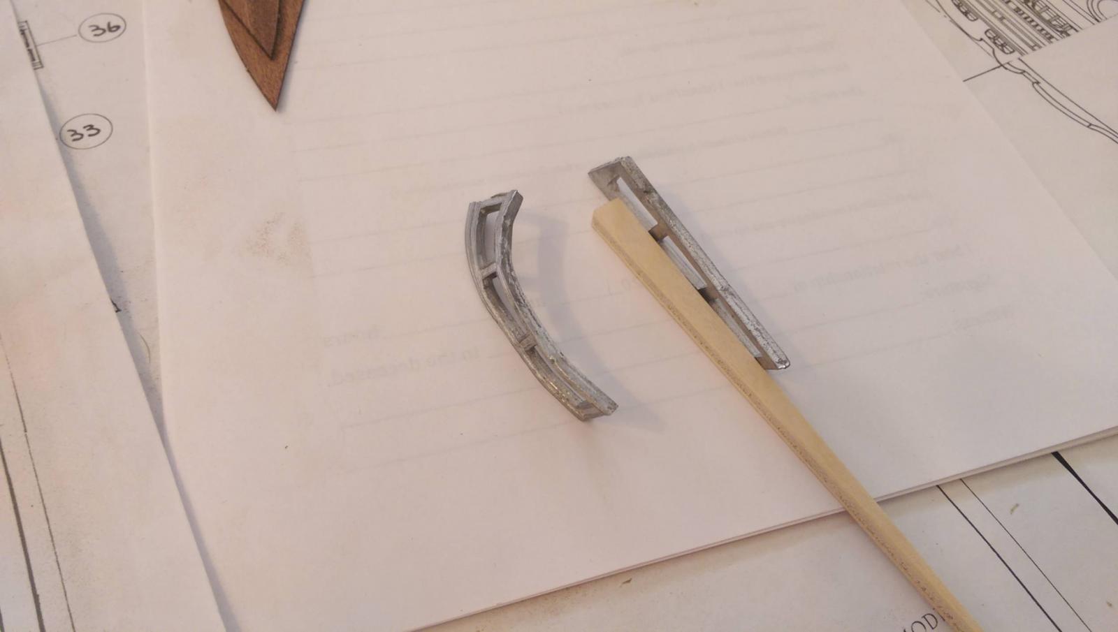
I am bending many of the metal castings and some require severe curving. To prevent breakage, I use a butane torch. I heat the metal to just hot enough that you can't touch it, so it doesn't melt. Then use an anvil and tiny hammer to gently tap the metal. It bends easily and does not break. Vince P.

- 593 replies
-
- 3
-
-
- royal william
- euromodels
- (and 1 more)
-
Just learned another lesson the hard way. As you know, I cut out the tiny window panes in the metal gallery castings and filled them in with a liquid window glaze. They came out very nice and look like real glass. I then glued the castings in place using very little CA glue. It seems the fumes from the glue turned most all of the nice panes white. It took about a day for the white to show up. . I had to remove the castings and scrape out the windows and do it again. Now I have to figure out what glue to use that won't fog up the windows and still be strong enough. I don't think PVA glue will hold metal very well. Vince P.
- 593 replies
-
- 2
-
-
- royal william
- euromodels
- (and 1 more)
-
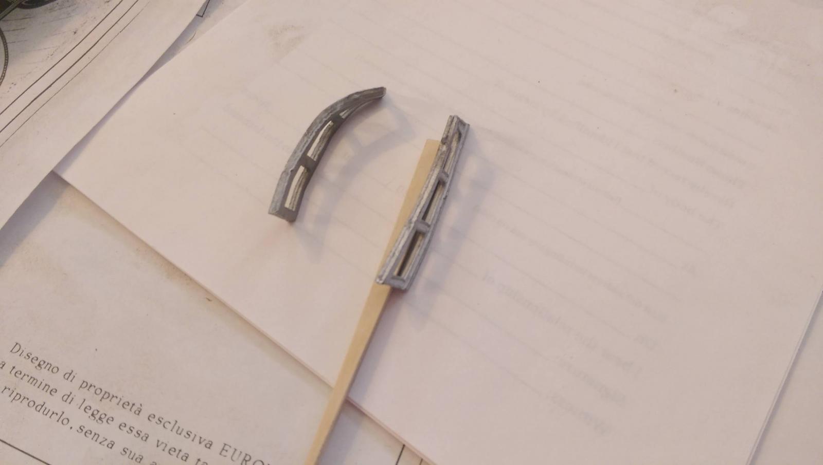
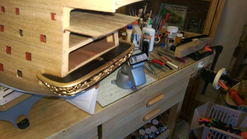
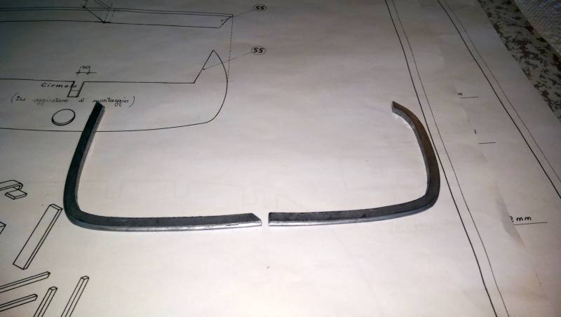
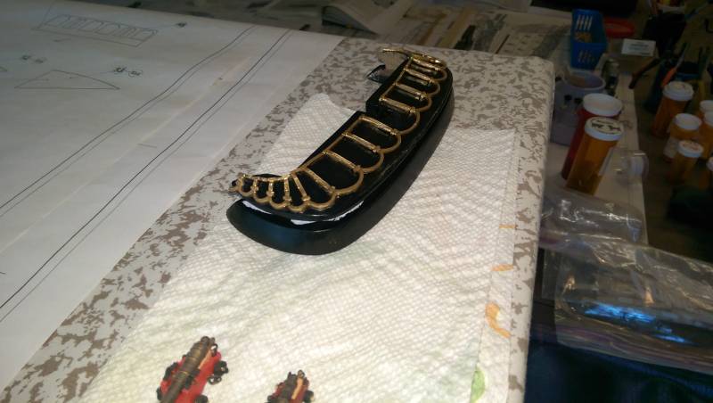
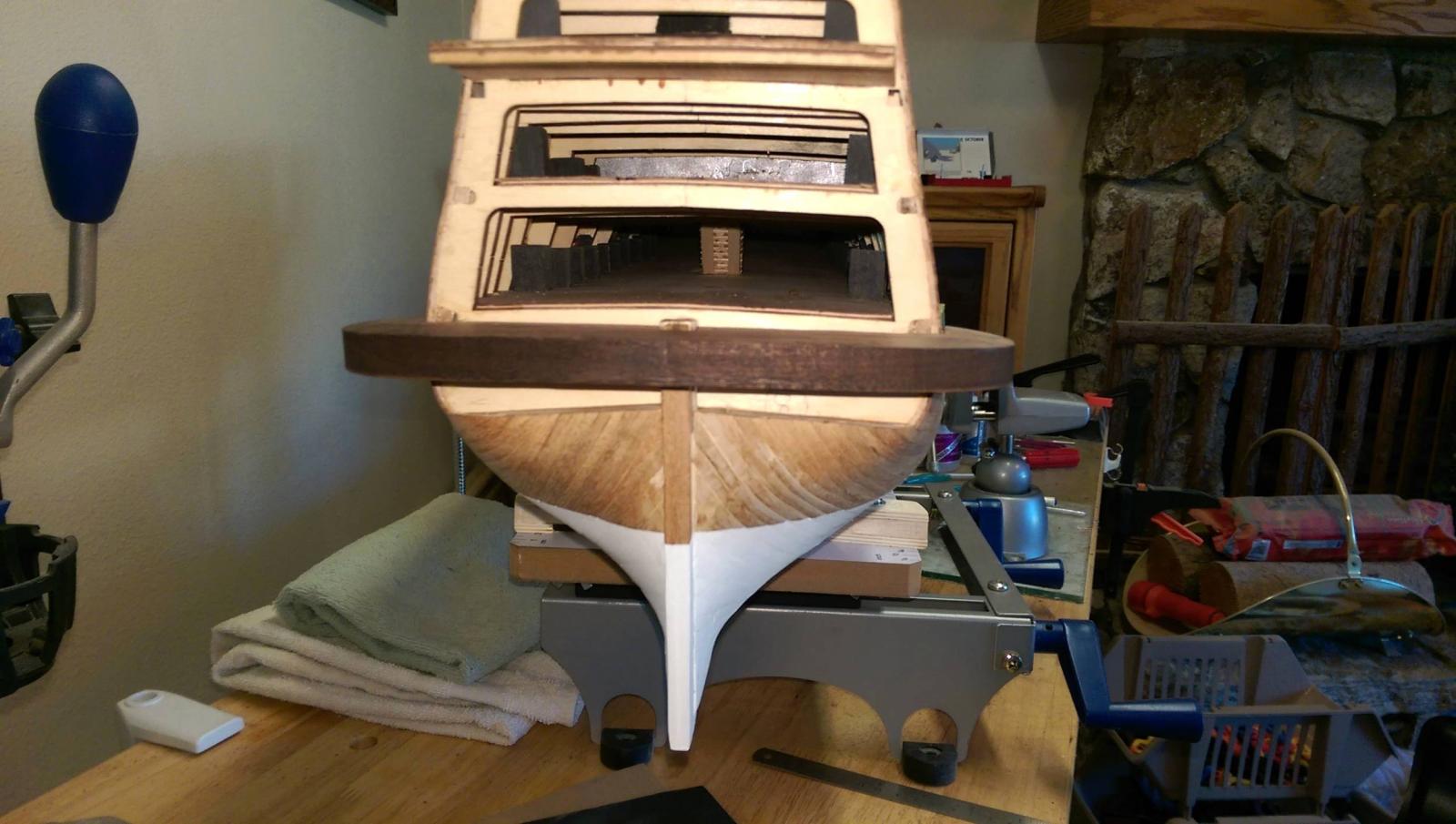
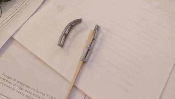
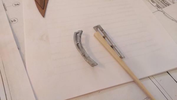
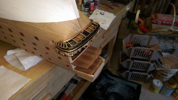
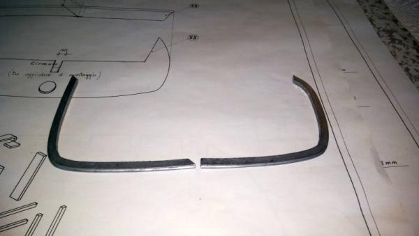
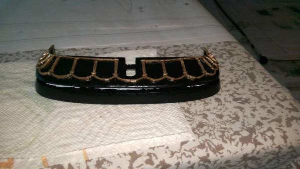
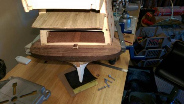
I am still working on the transom base. The base has been mounted on the hull with all of the decorative pieces except for the top rail. It will be placed once I flip the hull over. The last photo shows how much the metal trim has to be shaped. The piece on the left is before and on the right is after. The metal is hard to bend without breaking and requires a little heating to make it softer. I used a plastic hammer and an anvil to make the bends. There are 4 gunports in the transom base. The lids had to be made from scratch and were placed along with the hinges and pull ropes. Vince P.
- 593 replies
-
- 9
-
-
- royal william
- euromodels
- (and 1 more)
-
Great work Denis, as usual. Vince P.
-
Micro-Mark MicroLux LaserKnife 2525 – A Review
pirozzi replied to mtaylor's topic in Modeling tools and Workshop Equipment
Thanks Mark, for your feedback. It is appreciated that you put all this work into keeping us posted. Vince P. -
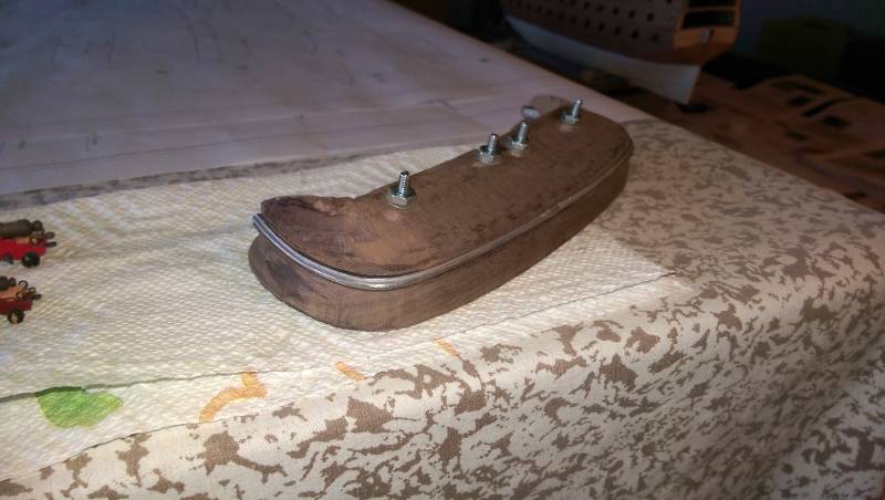
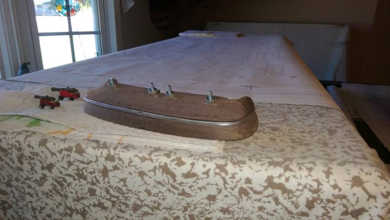
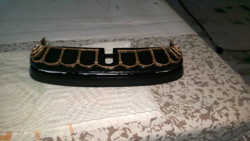
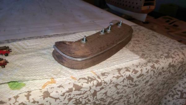
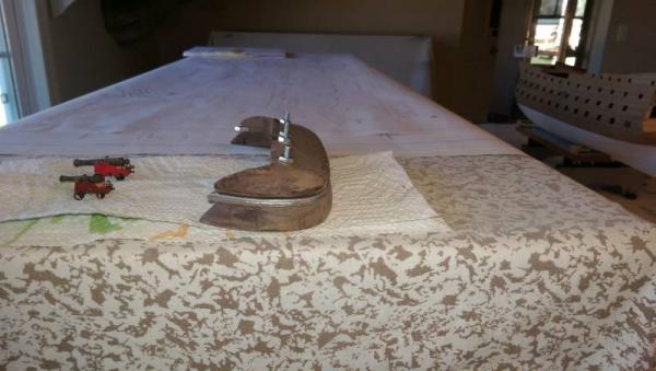
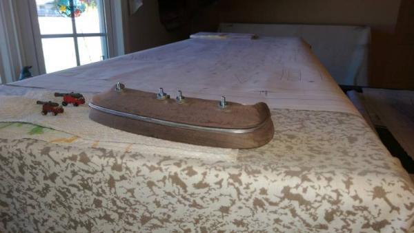
The transom base pieces have been fully carved and the channel cut for the metal trim. A hole has been cut for the rudder post and the whole thing painted black. Two pieces of the decorative metal have been placed. The metal is painted gold and then bent to conform to the wood base. The pieces have to be carefully trimmed of extra metal. The metal is very fragile and has to be bent ever so carefully to prevent breakage. Vince P.

- 593 replies
-
- 10
-
-
- royal william
- euromodels
- (and 1 more)
-
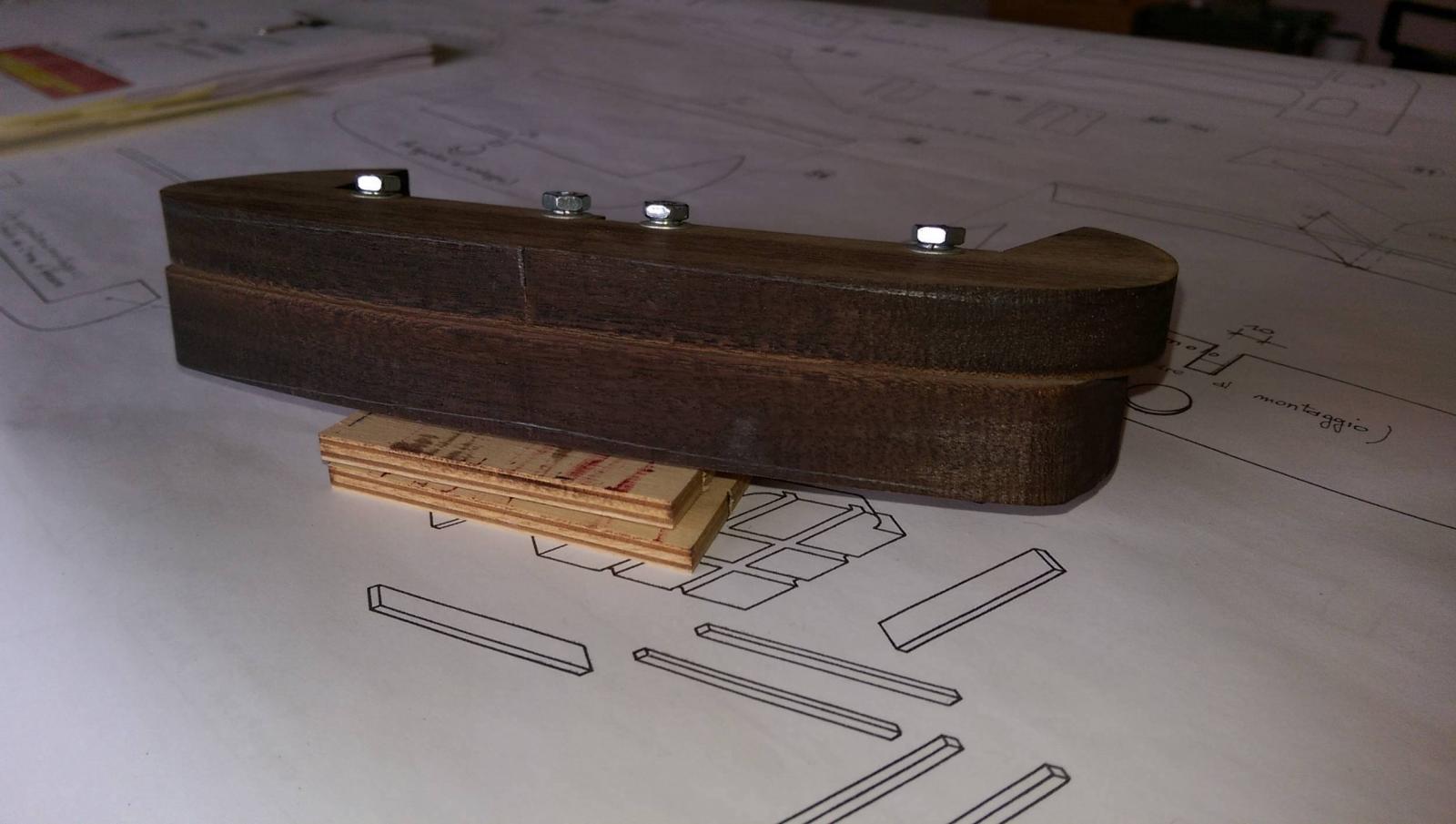
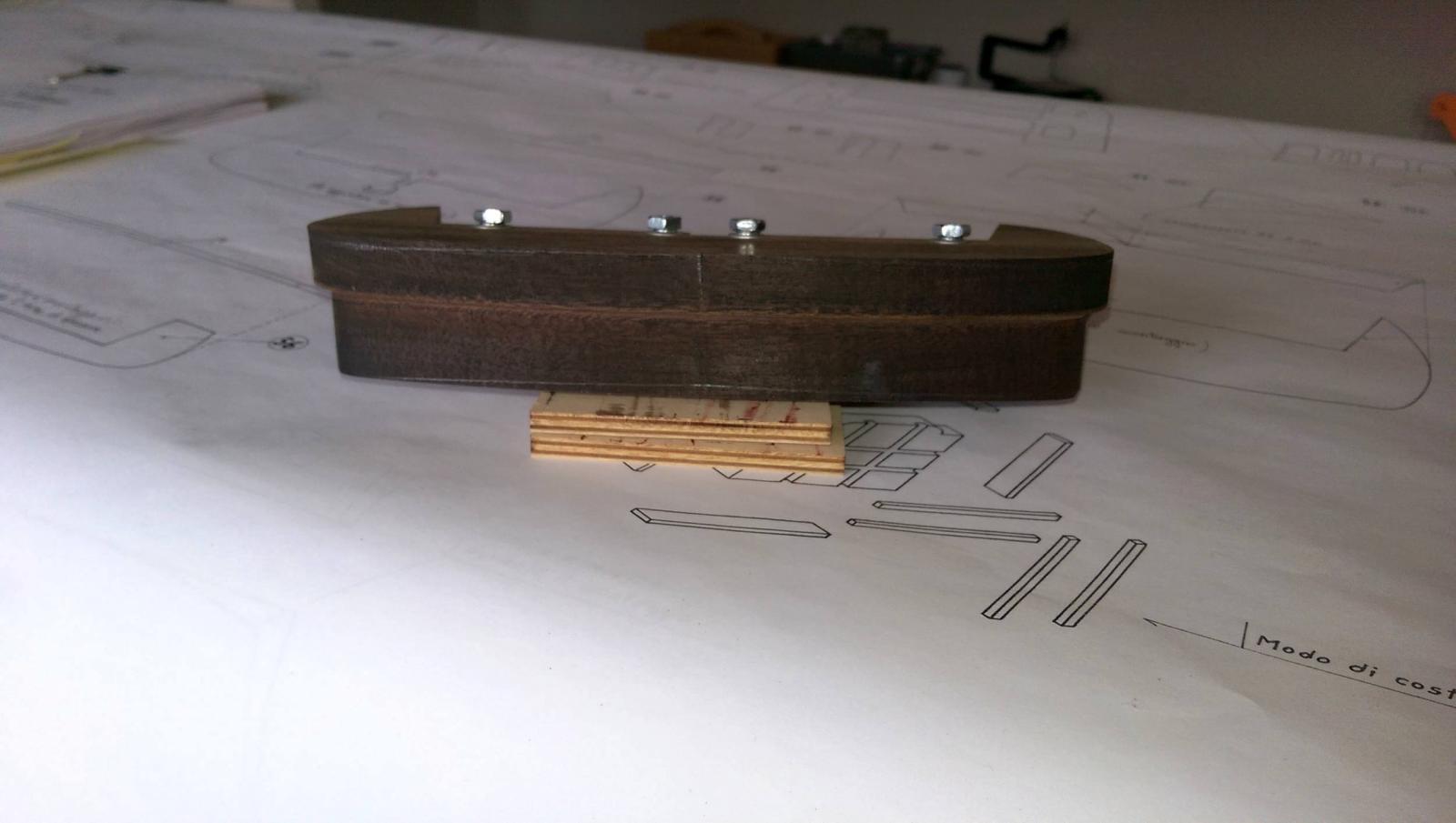
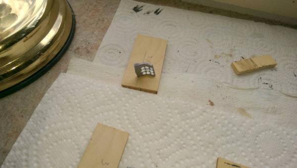
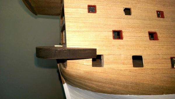
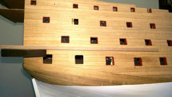
I have started to tackle what I believe will be the most challenging and difficult part of this build. That is construction of the transom and stern galleries. There are 2 ways to build these. One is using the plan drawings from scratch and the other is using the carved metal trim pieces included with the kit and using the plans for measurement references where necessary. Pete's notes in the Euromodel references cover both and Keith Julier's article deals only with the first choice. I have decided to use Pete's notes and the second method. There are 3 wood pieces that make up the transom base and they will require a considerable amount of carving in every plane. The parts are #56 which is a thin plywood piece, parts #55 and #54 which are thick walnut pieces. Since I am using the metal carved trim pieces, Part #56 will not be needed on the ship, but must be used to mark the edge of the bottom of piece #55 for carving. The first thing to do is temporarily join all 3 pieces together with either bolts or dowels so the edges can be marked for trimming. Part #56 on bottom, #55 in middle, and #54 on top. Line up the sternpost slots with a piece of 10mm wood and the forward edges of all the pieces. The first 4 photos show this. Next up is to seperate the pieces and work on #54 by shaving the top and bottom to form the correct camber. The piece is reduced in thickness from 13.0mm to 10.5mm. Once that is done, place the piece on the stern and mark where it will be heightwise. The distance from the top of the upper quarterdeck to the top center of #54 should be 98.0mm. The piece should also be slanted downward slightly. There are differences of opinion on what the declining angle should be, but I agree with Pete and the line of the lower gun deck should be in line with the top of #54. In order to get #54 to butt up against the last bulkhead, a considerable amount of wood has to be cut away on the insides of both ends to match the curve of the hull planks, and the slot for the sternpost has to be deepened as well. The lower edge of the outside surface has to be carved back using the mark made with the edge of #55 to form the inward cant, and the ends have to be trimmed back and beveled to wrap around the last lower gunport. Both Pete's notes and the plans have good drawings to reference this. Once the piece is sitting correctly on the stern, mark the edges all around with pencil lines and remove it for later. Vince P.


- 593 replies
-
- 8
-
-
- royal william
- euromodels
- (and 1 more)