No Idea
-
Posts
1,036 -
Joined
-
Last visited
Content Type
Profiles
Forums
Gallery
Events
Everything posted by No Idea
-
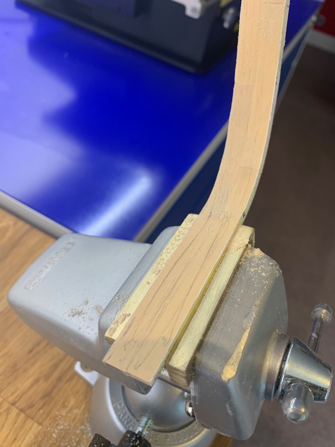
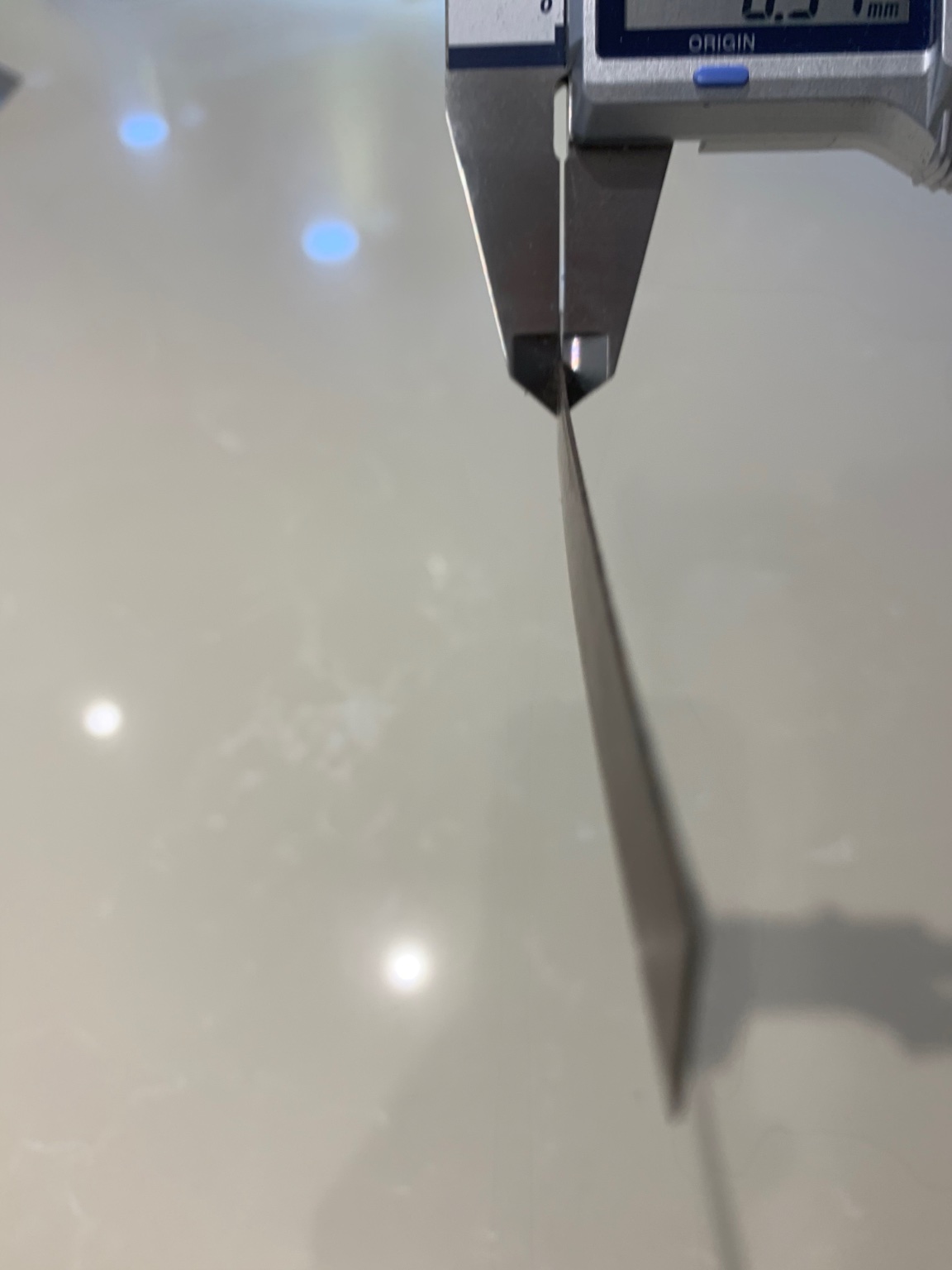
 The mill is indexable on each axis. So I mark out the width with pencil and then touch to cutter to the surface. Then drop the cutter 0.5mm and make the passes. I check the width using a vernier so that I know its correct
 -
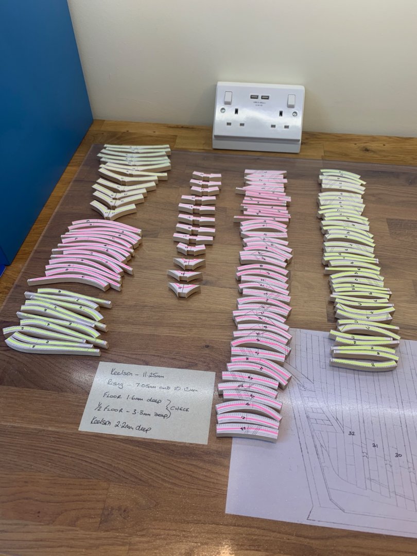
Hi clogger the floor side is the side of the frame that sits the lowest on the rising wood. The half floor is raised slightly - If this doesn't help drop me a PM and I'll do my best to help you more. The good news is I've now sorted out the home heating I'm just waiting on the plasterer to arrive tomorrow to patch up the holes that we had to make in the walls and ceiling. So I'm now back onto this build and I'm very happy about that. Today I've been milling the slots for the floor chocks and drilling the holes for the frame bolts.

-
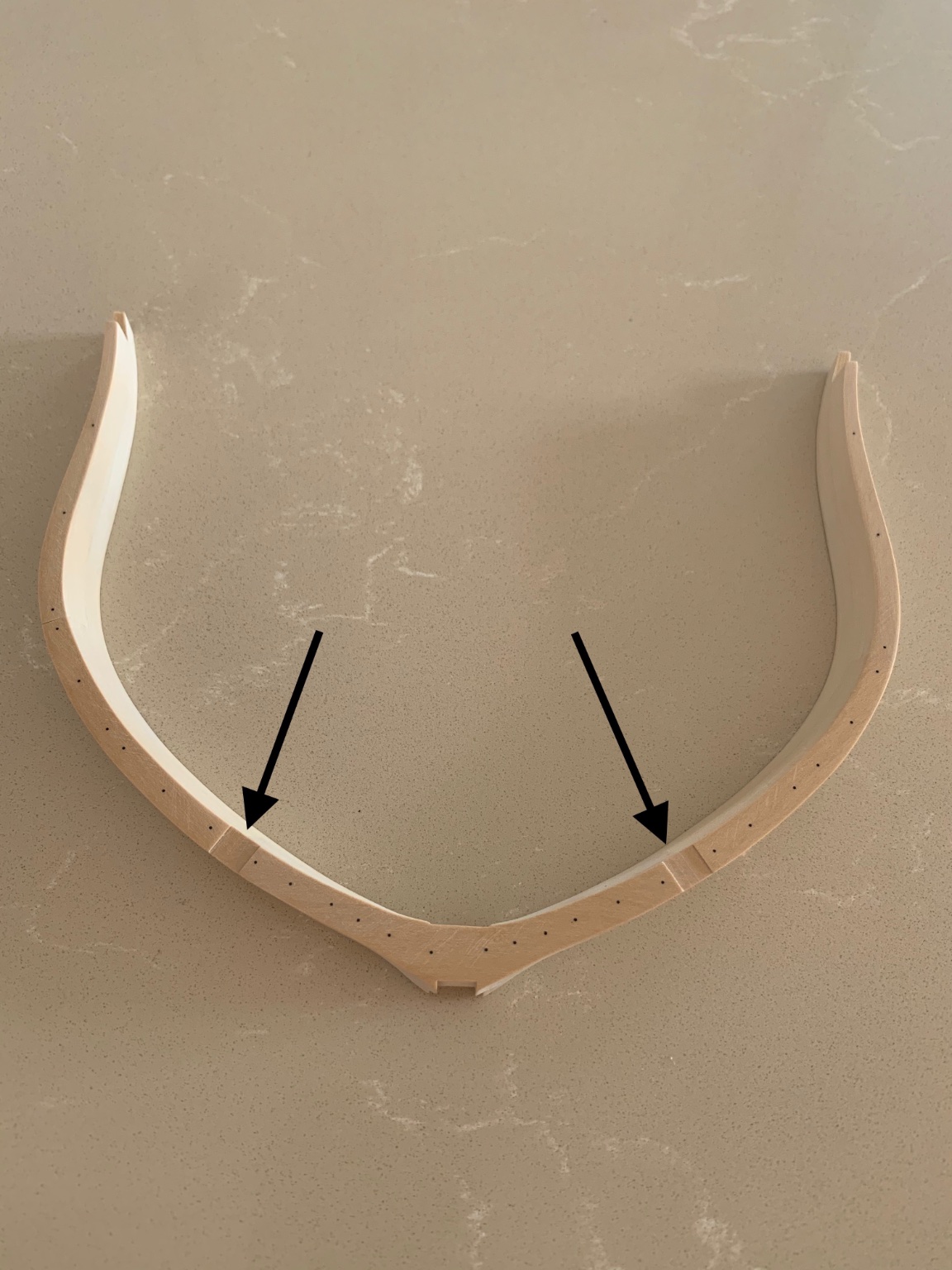
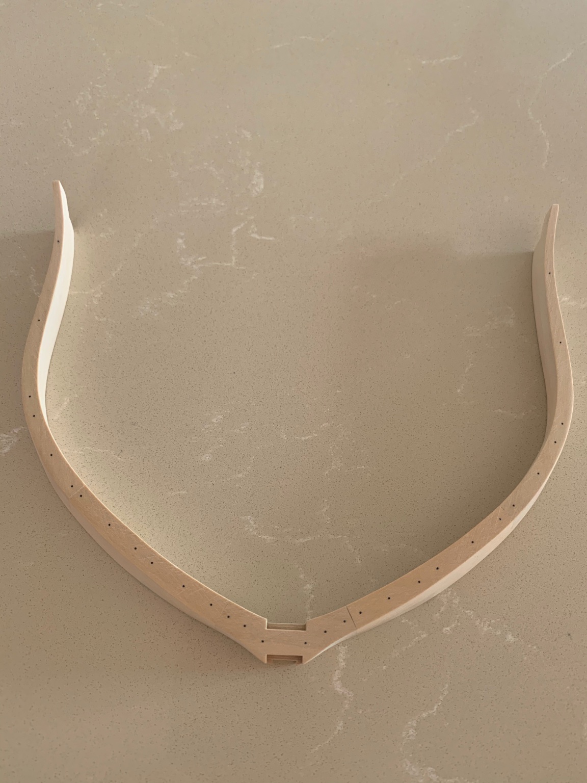
Hi Clogger - On frame 2 the floor side of the frame is the tallest. All of the floor side cuts have a solid line and this marks out the individual pieces. Similarly the dotted lines mark out the half floor side and this is the same for all of the frames. I'm sorry that I've not posted anything but our heating system at home has been causing us major issues. I've had to cut holes in the drywall to find a problem and its taking up a lot of my time to get it sorted out. Attached are a couple of pictures of frame 2 for you.
-
Hi Roger - I always clean my blades with something similar to this. Removes all of the gunk and restores its cutting ability. https://www.axminstertools.com/axcaliber-blade-bit-cleaner-500ml-104736
-
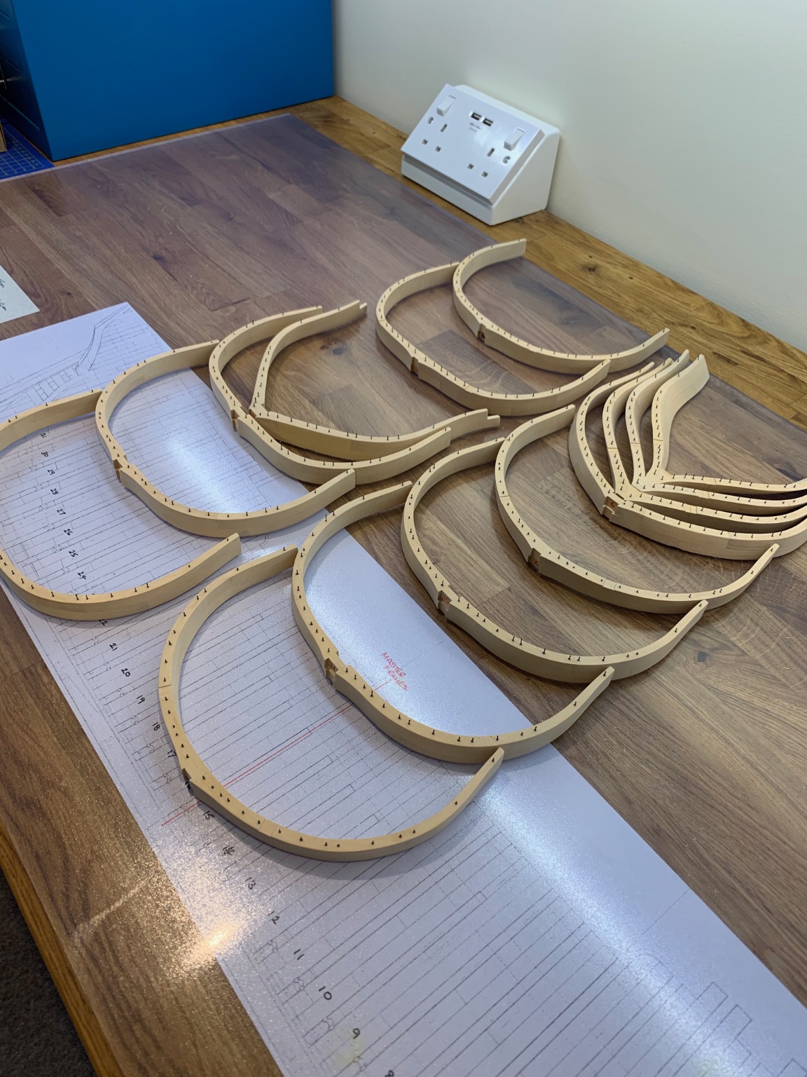
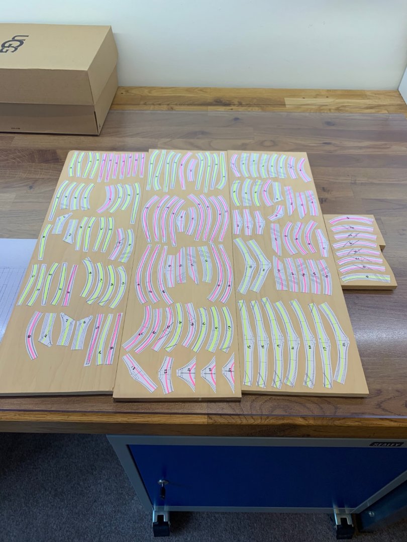
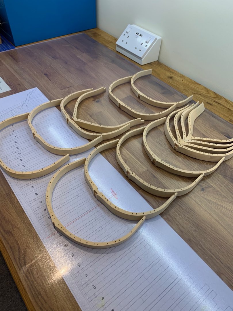
Another small milestone achieved today. I've now completed frames 16 - 27 and I'm definitely getting better at making them. Practice really does make perfect! I still need to cut the slots for the frame spacers and also drill and fit all of the bolts. I really do need to work on my butt joints though as I have a few which are really visible. They look OK when I'm gluing them up but a bit more precision on my part is required.


-
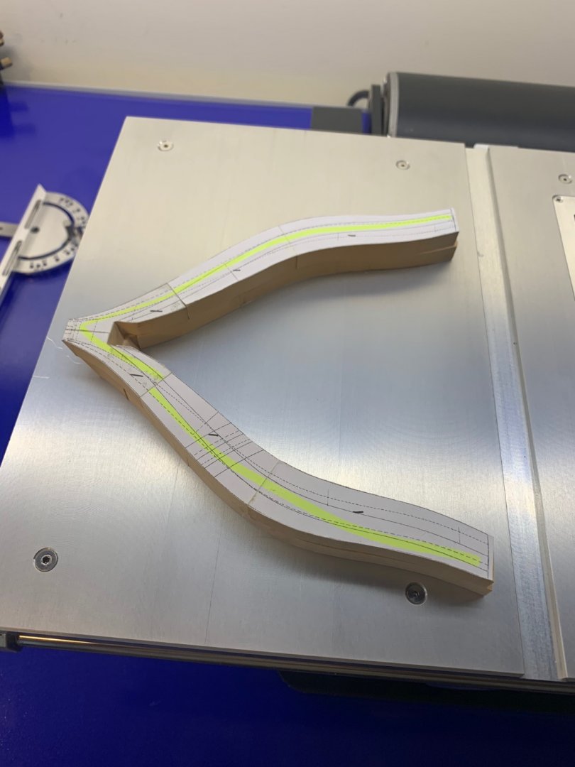
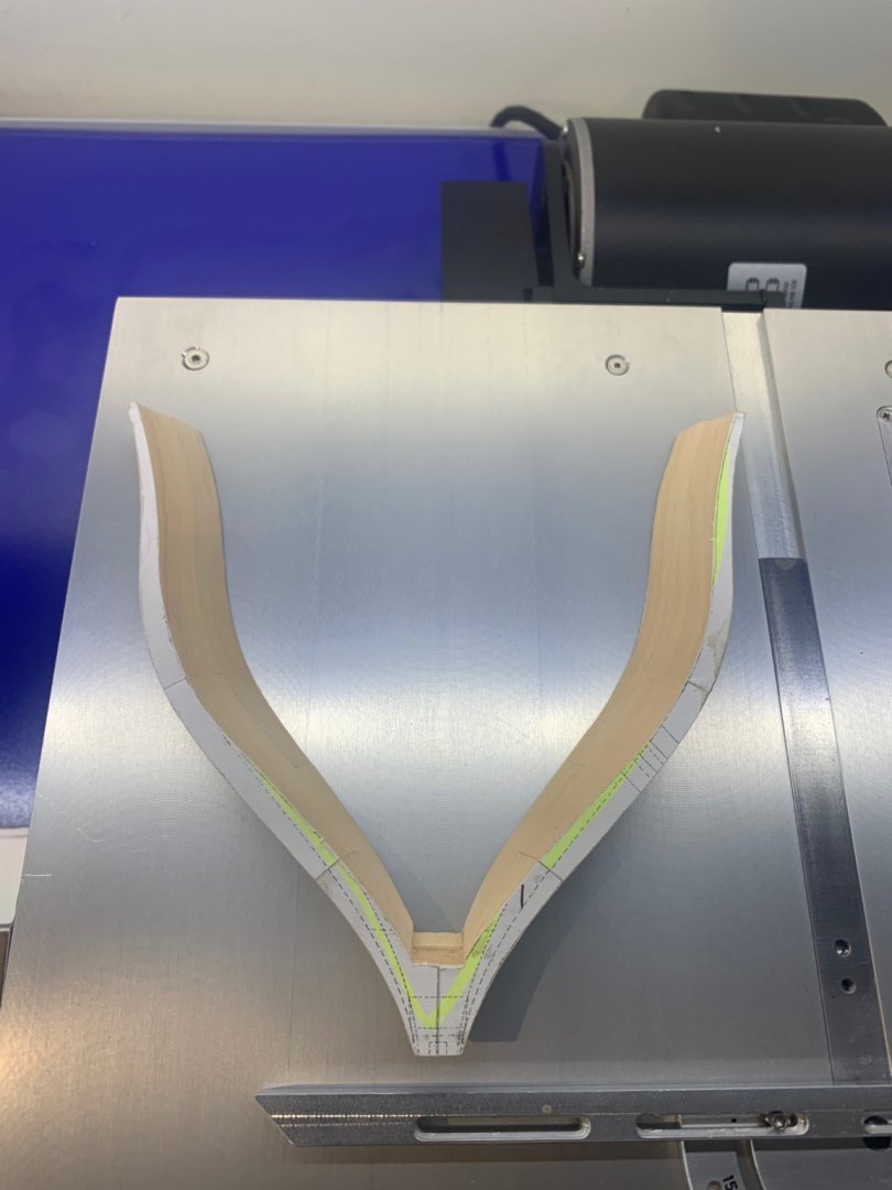
Hi Clogger and thanks for the nice comments I cut out the parts using a bandsaw but I stay away from the finished line. I then sand them down using a Dremel and a face sander before gluing them together. If you don't already have it I would recommend Adrian Sorolla's book called "An introduction to model ship building dockyard style". Its a full blown build of this model and I am using it as guide as this is my first POF build. What I do though is to make sure that when I sand the bevels the surfaces are sanded all of the way across. I think that this will make the assembly of the frames and final fairing a bit easier. I do this by simply using pencil witness marks on the piece. Just colour it in and you can see where you are sanding and also when you have achieved the flat face too. A few pictures below to explain. I use a file to do this work


-
Any soft solder will be ok - I still prefer the old type with the higher lead content it just flows better. Just have a good practice on something that doesn't matter and you will be ok. I should have said that the Powerflow flux is for soldering metals together only; never use this stuff on electrical connections.
-
Hi Dave - I can't vouch for the quality in any way but if all your going to do is the odd occasional bit of small soldering these will do you An 80W plug in iron £13.79 https://www.ebay.co.uk/itm/80W-LCD-Digital-Electronics-Soldering-Welding-Iron-Adjustable-Temperature-Tool/283979616080?hash=item421e810f50:g:1YoAAOSwWGNfN1N6 Or if you want to go with a gas soldering iron here's a pretty good make for £26. You can get cheaper ones and some come with a small gas torch adaptor https://www.ebay.co.uk/itm/GAS-SOLDERING-IRON-25w-80w-PRO-IRODA-SOLDERPRO-70-REFILLABLE-BUTANE-BLOW-TORCH/362052633206?epid=2147176154&hash=item544c04c276:g:VlQAAOSw21RbxwNF Use some Powerflow flux and you will have no problems. This is an aggressive flux that plumbers in the UK use for soldering pipework. I've used it for years and never had an issue. https://www.ebay.co.uk/itm/Fernox-FRY-Powerflow-Flux-For-Lead-Free-Solder-100-grams-WRAS-Approved/383565740013?_trkparms=ispr%3D1&hash=item594e4cb7ed:g:R9MAAOSwLEdfNZM9&amdata=enc%3AAQAFAAACcBaobrjLl8XobRIiIML1V4Imu%2Fn%2BzU5L90Z278x5ickkxFtV7J5P58ubuVigtBH%2Fey0ngebVyVAiyrzn%2FM%2F9TIttaXRgTC94tVdLWWclQb3zAIuzuu4gCMS47M1lHBRPE%2FSHXWXlm3rA1MCvKBdA9pzD%2BKjOltq2pJftFrbgvty8Vk3LyBPpkayBJdLMcBI25zdo%2FRjxGjv%2FTfikZzDpOpXGbvMMCcI85D7SyE7gbLb8upBeoebOwflvD%2B4xRaDeYMb5SiNDg%2B0PhQeXqbHK9JRuxyQCVKwHhA6tWZkzJC7LUhwEqIMmkYsFgnVaXN%2BzeQ8lbZgvE5kdQvucv7PtcXAizYxWWlITWDweX319HjrohTlYccBekicsVKz0DYogJw52Xuzvy6sIBuDKI8VxiIebas9qdLn6zFlTSLoz5ChCI3iE%2BXkVqiaER3ovvgSwo4ShZWbUJQjYNrATokLHn%2BUJ7jgYhwVT3eedl0XaFpvOFb0cZt3D0uue1Y7vxQnUNSFGC2A%2BMHGuXyiSdqDaSYL2w6DM85BZXhFH%2B1eOgbkXB%2FEIBLjJJiKgbUks0Z1S7R3mJX%2FRM3uyXaySGuQtI26owYEzrvZ8nHtsq4SW4K%2F4zrv5d2iClim2vA4gK1x1j29sW569npqXJtbUqcxaR94t9ysgktPG%2FfSpHqd4o6R%2Fzudl%2B6Ww3%2FbmZm%2BDBbx1JWF1ZZ0PzMFvkQcgZUGoqXQUotR60%2BOVrLk5H27Gvq1%2FGs%2BANC17Kd7jHT3h91SWwUgeDe4O4uf%2BLZ2hkOUGcr8cgoNQnYK7kczBsfs8A3ybMDuDIUVTdM3UFXpFTZXVqg%3D%3D|cksum%3A3835657400136ee460c97e55433c906e775df77bac7f|ampid%3APL_CLK|clp%3A2334524
-
Hi Dave - The problem with using a gas soldering iron with soft solder is one of heat. If it's too cold it won't solder and if its too hot it won't solder either. They do not have any kind of way of measuring their heat output other than the size of the flame under the tip. Electric irons are set to work at the best temperature and generally always work. I only use gas with silver solder and then its a pure flame. I've never had much success with a flame and soft solder as the temperature is critical.
-
Hi Dave - If you really want to get one for modelling I can honestly say that I have the cheapest and lowest wattage soldering iron you can get. It cost about £20 and I've used it a few times on copper and brass parts but I could have just as easily glued them together. The type of solder and flux is pretty irrelevant as cleanliness is the most important thing when soldering. Clean the parts with wire wool to remove all residues and then get going. The all singing and dancing soldering stations are great for electrical engineers but well over the top for your average modeller in my opinion. Buy cheap and practice.
-
Miniature Russian carving tools
No Idea replied to druxey's topic in Modeling tools and Workshop Equipment
I too have ordered a set from Mikhail - He must be quiet at the moment as I paid for them today and he is starting work on my order in the morning. I've gone for the full set with pear handles as I just couldn't justify the extra cost of the nicer handles even though they look amazing. So if you want some now the time to order and as others have said Google translate works great and he takes payment through PayPal so no risk either. -
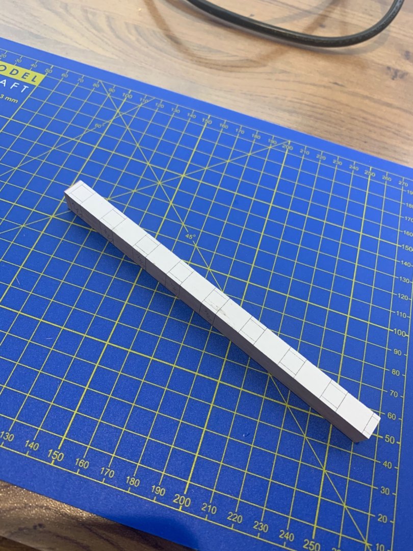
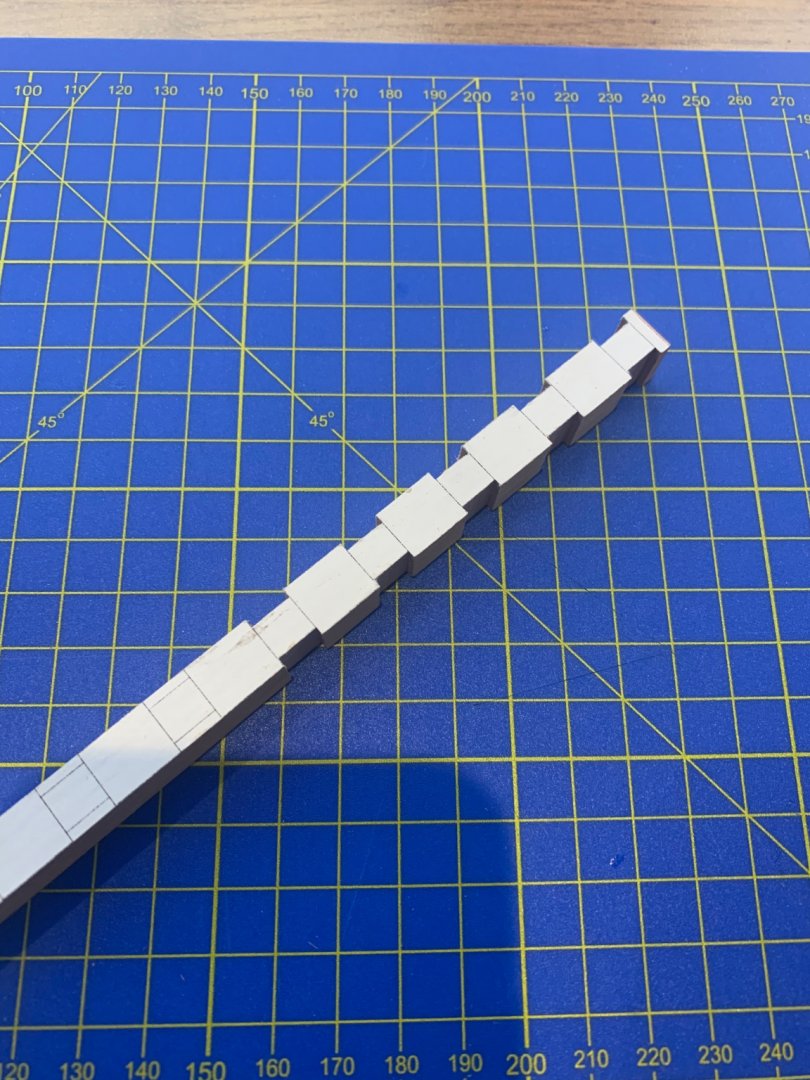
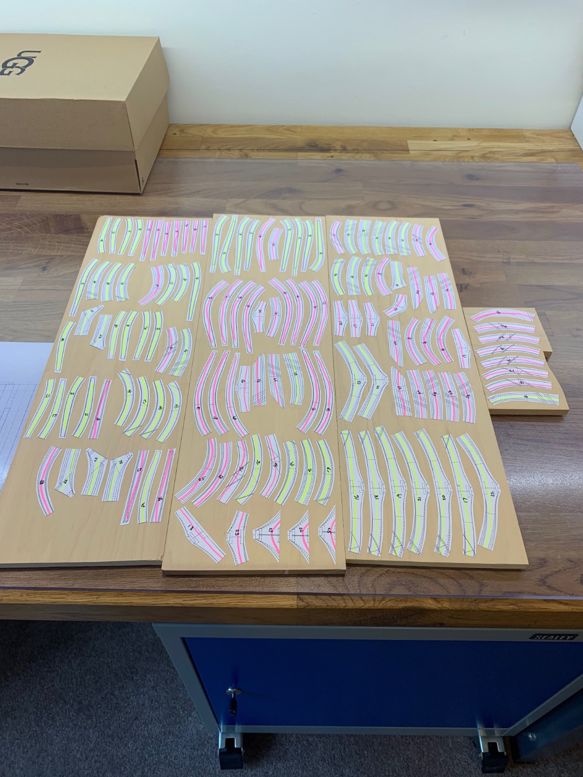
I've now finished all of the bolts in the forward frames and there's nothing else I can do with these until they get installed. I've now packed them away for sometime in the near future. So I've made a start on the aft frames - I'm starting with the 12 standard frames (Is that the right terminology?) that are not rising. I ran the wood through the thickness sander and made the templates as before. This time though I used 100gm paper and I have found it to be much better than the standard 80gm photocopy paper for the templates. It holds its shape far better and is just stronger when it's glued to the wood. Since then it's just been a case of hours of cutting, sanding, milling and filing the 133 parts which is where I'm at now. Next up is to start gluing the frames together and then get sanding again.
-
No pressure there then - the master Jedi is watching your build
- 589 replies
-
- 6
-

-

-
- le gros ventre
- cargo
- (and 1 more)
-
The results speak for themselves and I see a masterclass in CNC programming. It must be so difficult to work out all of the cutting passes and just how to hold the piece which probably needs turning around. How you work out the datum on something like that is incredible. This is an art in itself and more than likely the future of model ship building. I just wish that I could do it to be honest
- 589 replies
-
- 4
-
-
- le gros ventre
- cargo
- (and 1 more)
-
Hi Tony I get all of my wood from here https://shop.exotichardwoods.co.uk/boxwoods/page/4/ Although you can buy these pieces that are already cut, if you give them a call they will cut you pieces to your own sizes for a small charge. I simply worked out what I needed and gave them a call. The frames on this build are 7.90mm thick so I ordered the wood to be just over 8mm. I then just cut the planks into three to make them more manageable and then ran them through a thickness sander. Mark
-
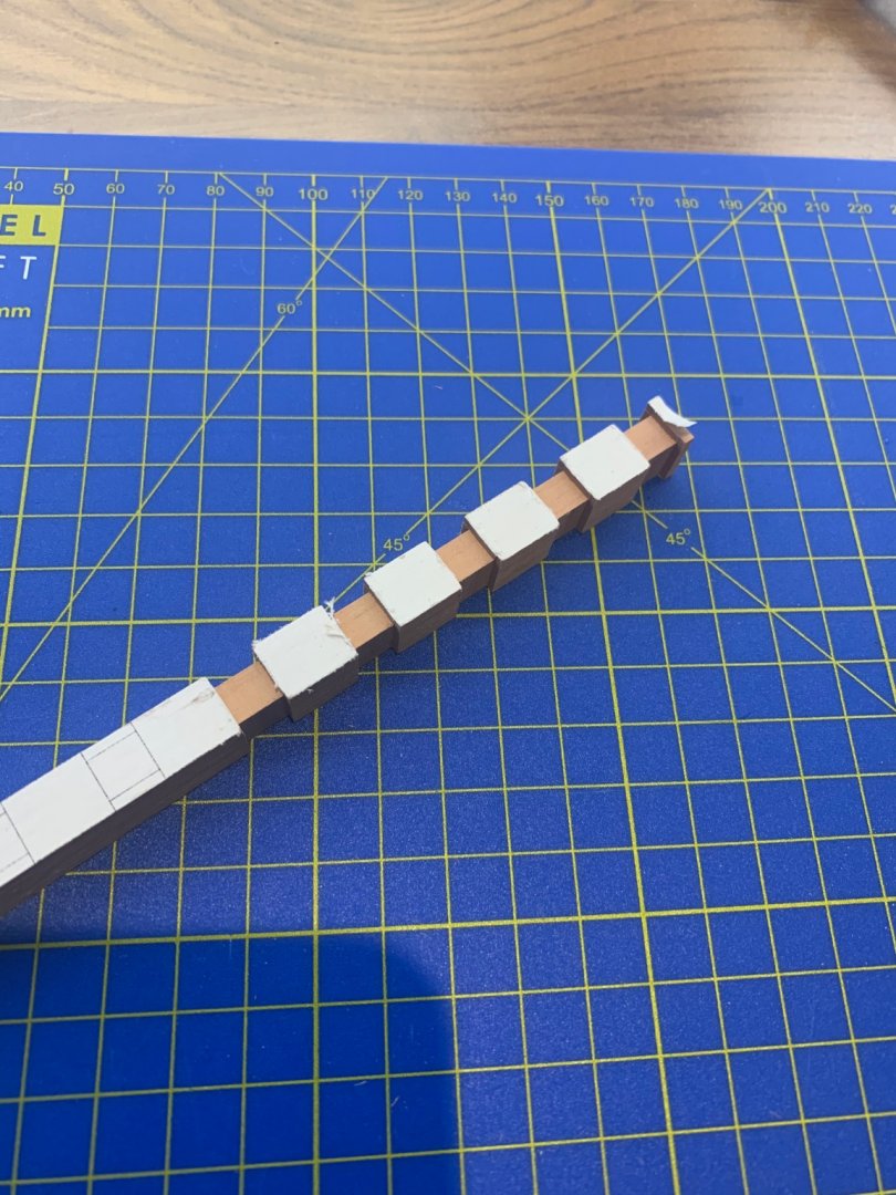
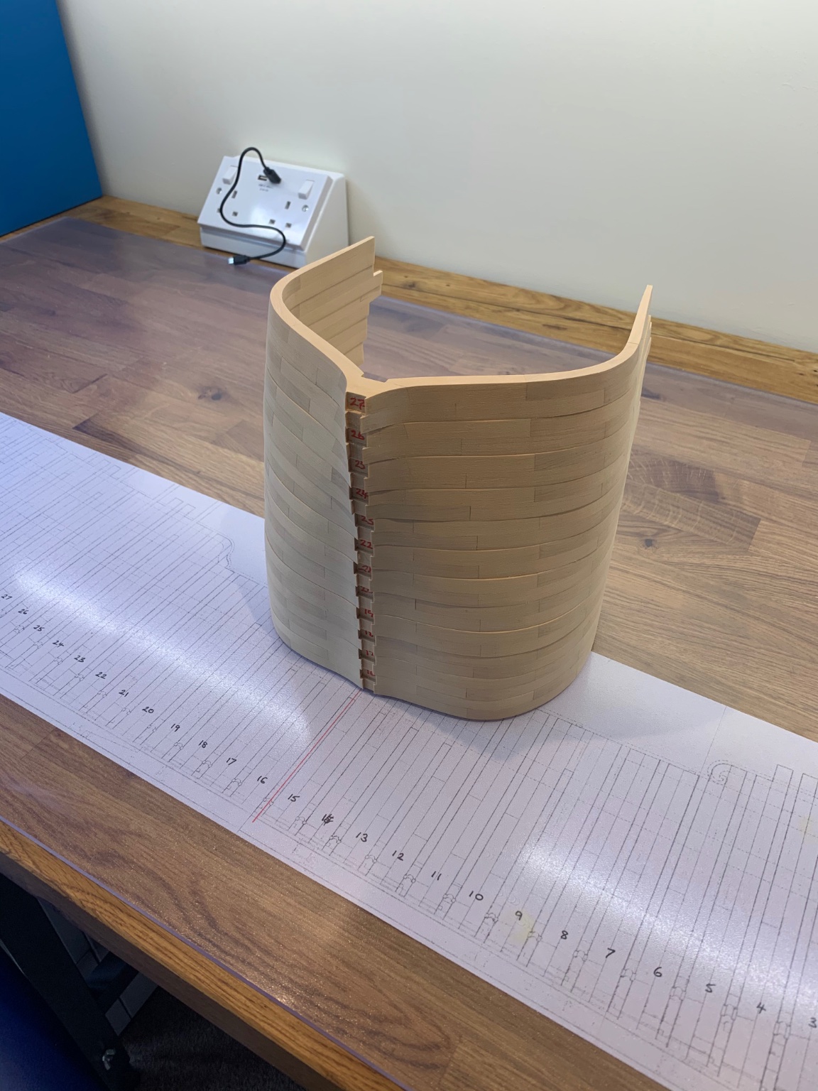
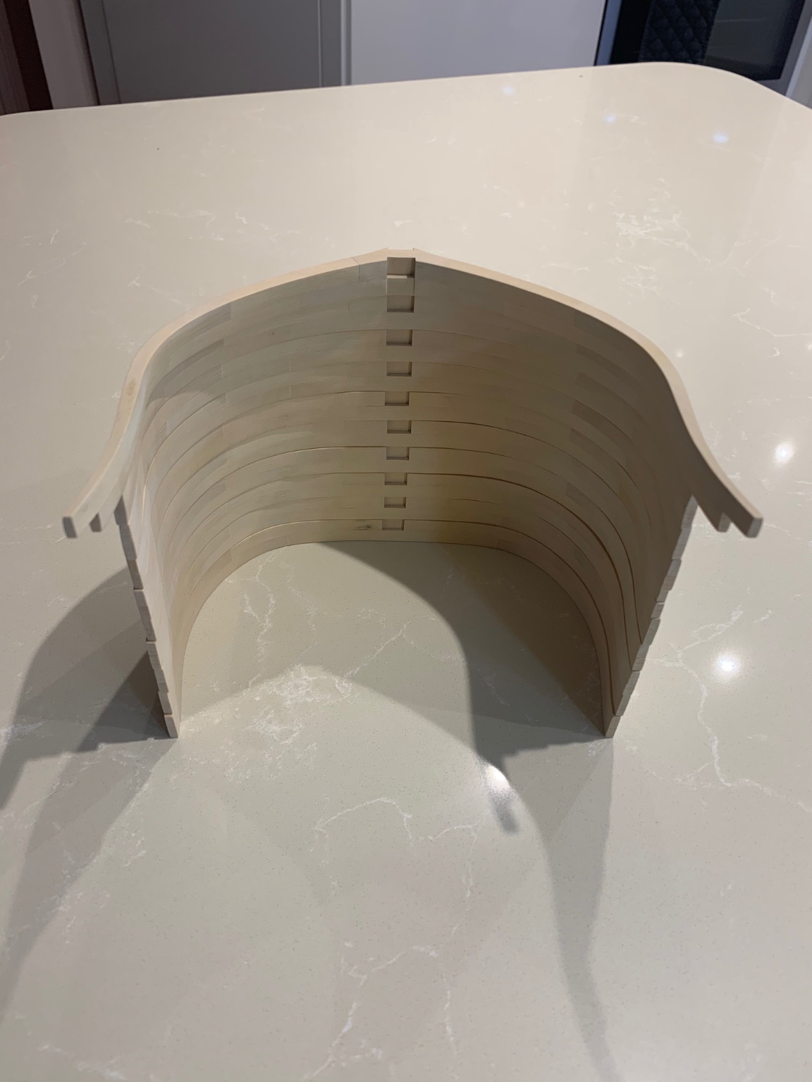
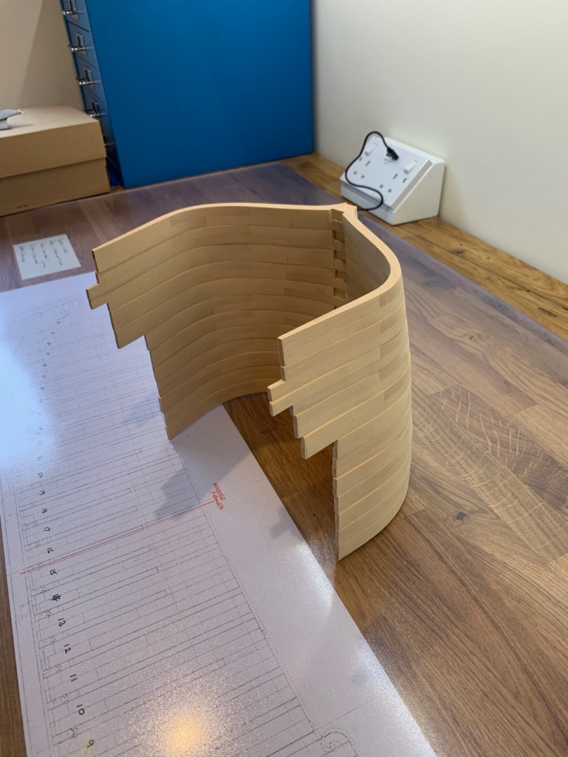
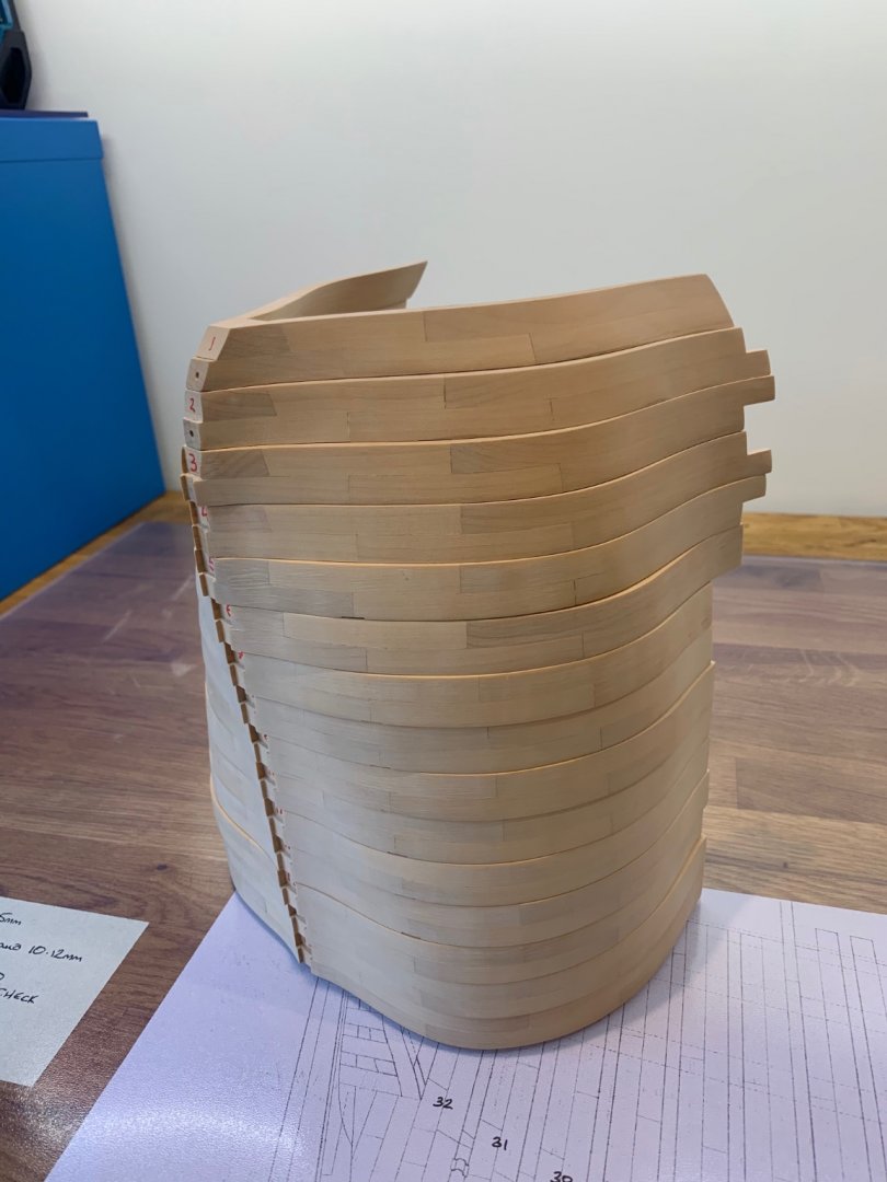
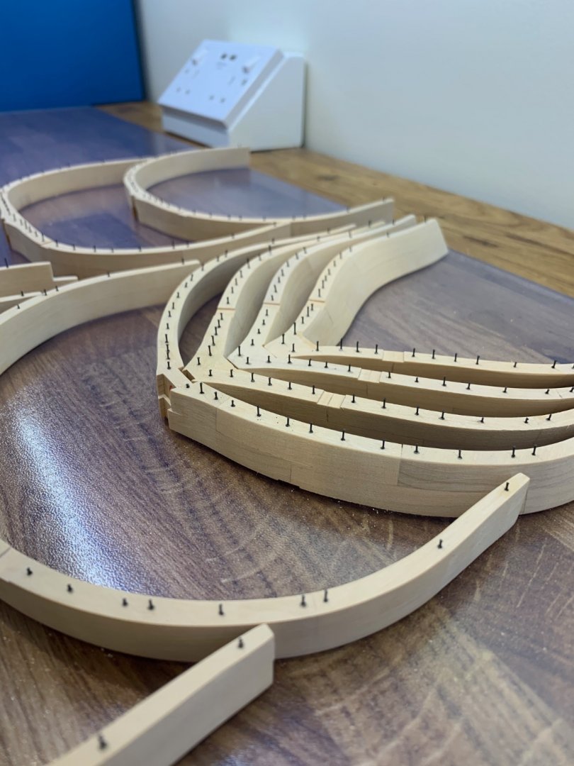
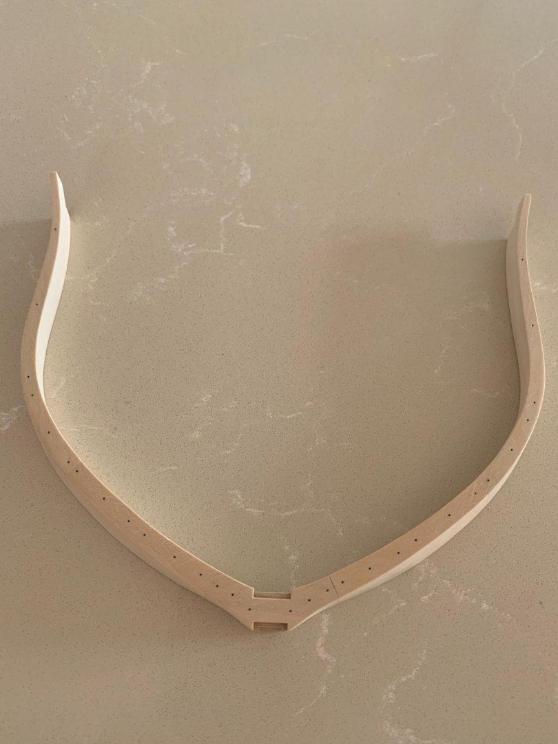
I'm now getting on putting in all of the bolts into these 15 frames - all 900 of them. I've already used 4 metres of 0.5mm carbon rod so I'm glad its really cheap to buy! Also a picture of the frames so far not quite lined up correctly. I just need now to get these bolts finished and clean up the frames. I guess I can then start on the rear frames.

-
I've managed to get some more done. I've now completed the 4 forward rising frames but not without a problem. I found an error in the frame that I made above so it had to be made again. No big deal as I would rather it be right to save problems later.

-
Thanks Tony thats a good suggestion - As this is my first POF build I really want to do things the right way as much as possible. I want to hopefully make a nice job of it and learn as much as I can for future builds. Well if I survive this one
-
Thanks Mark much appreciated
-
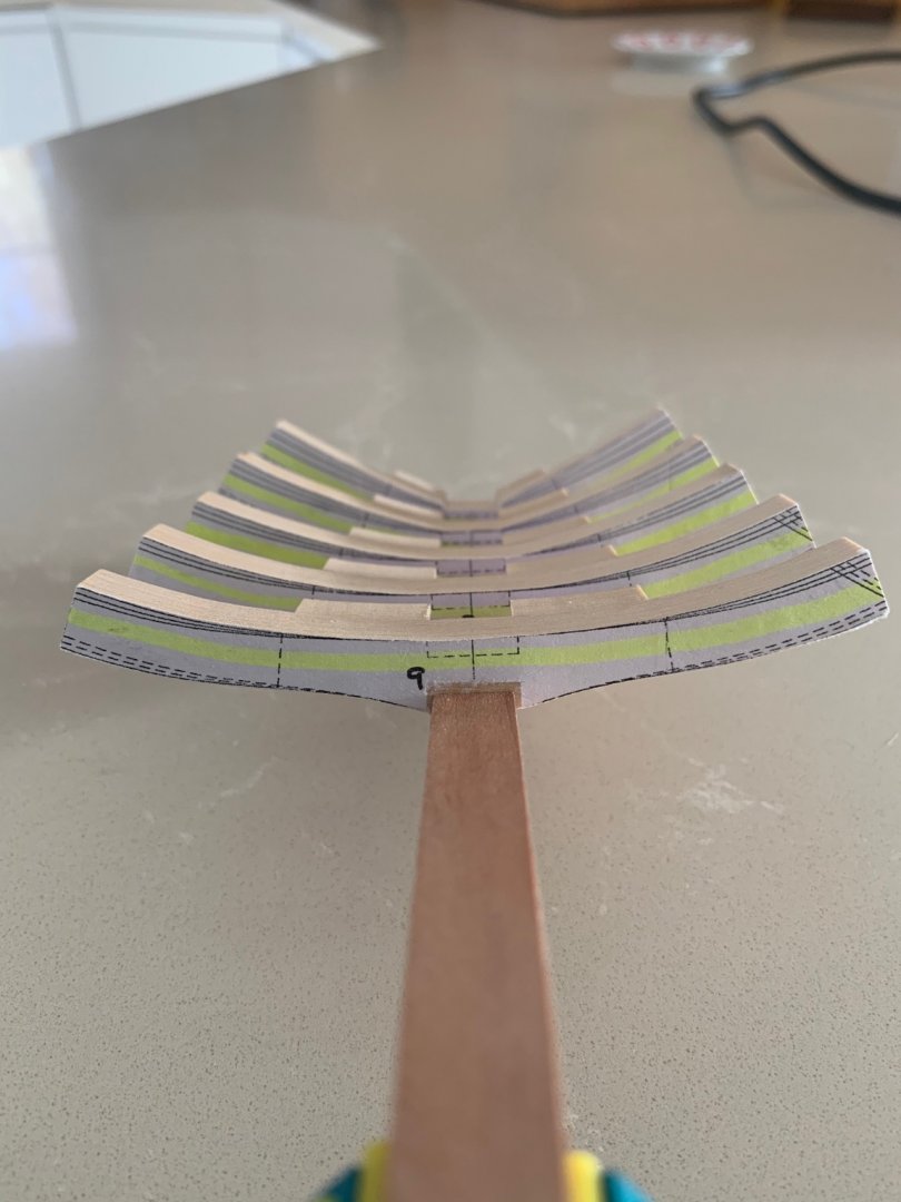
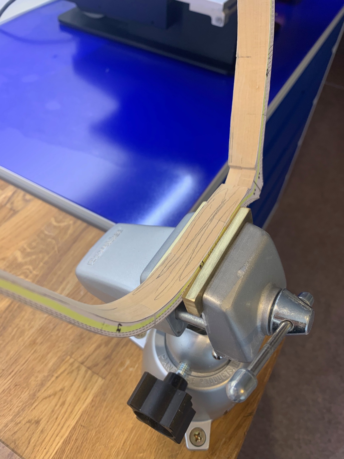
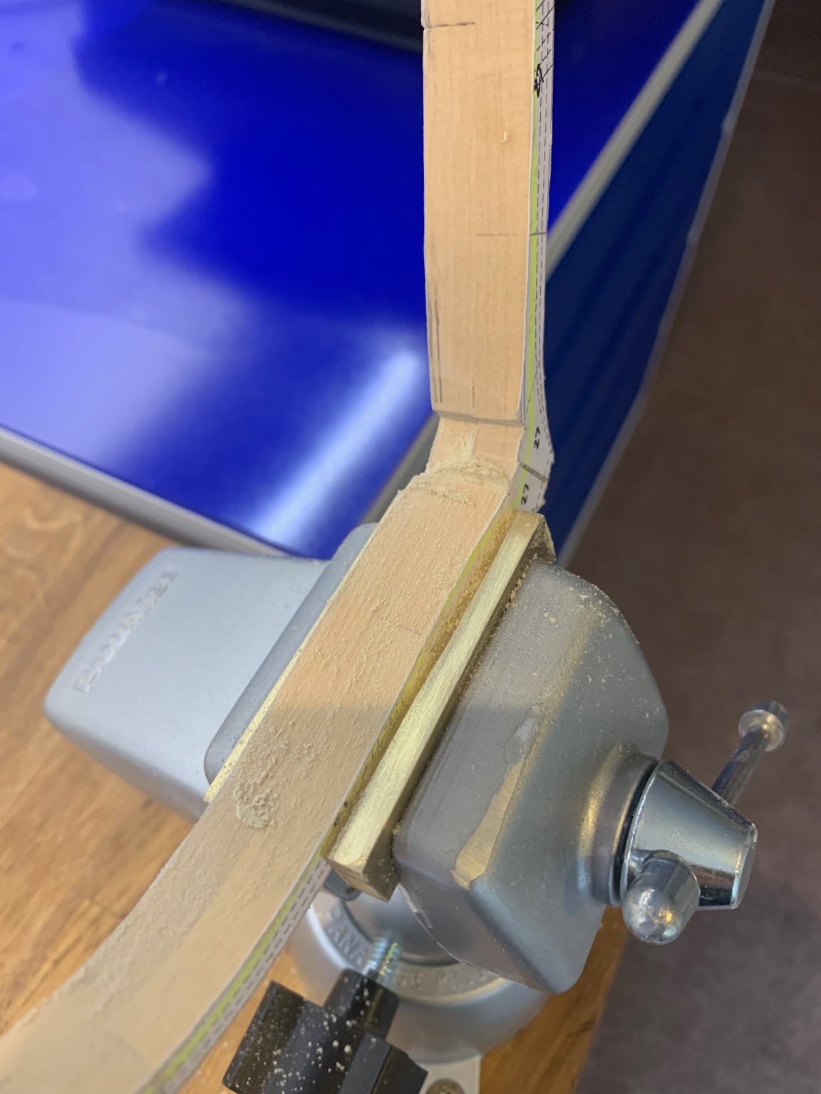
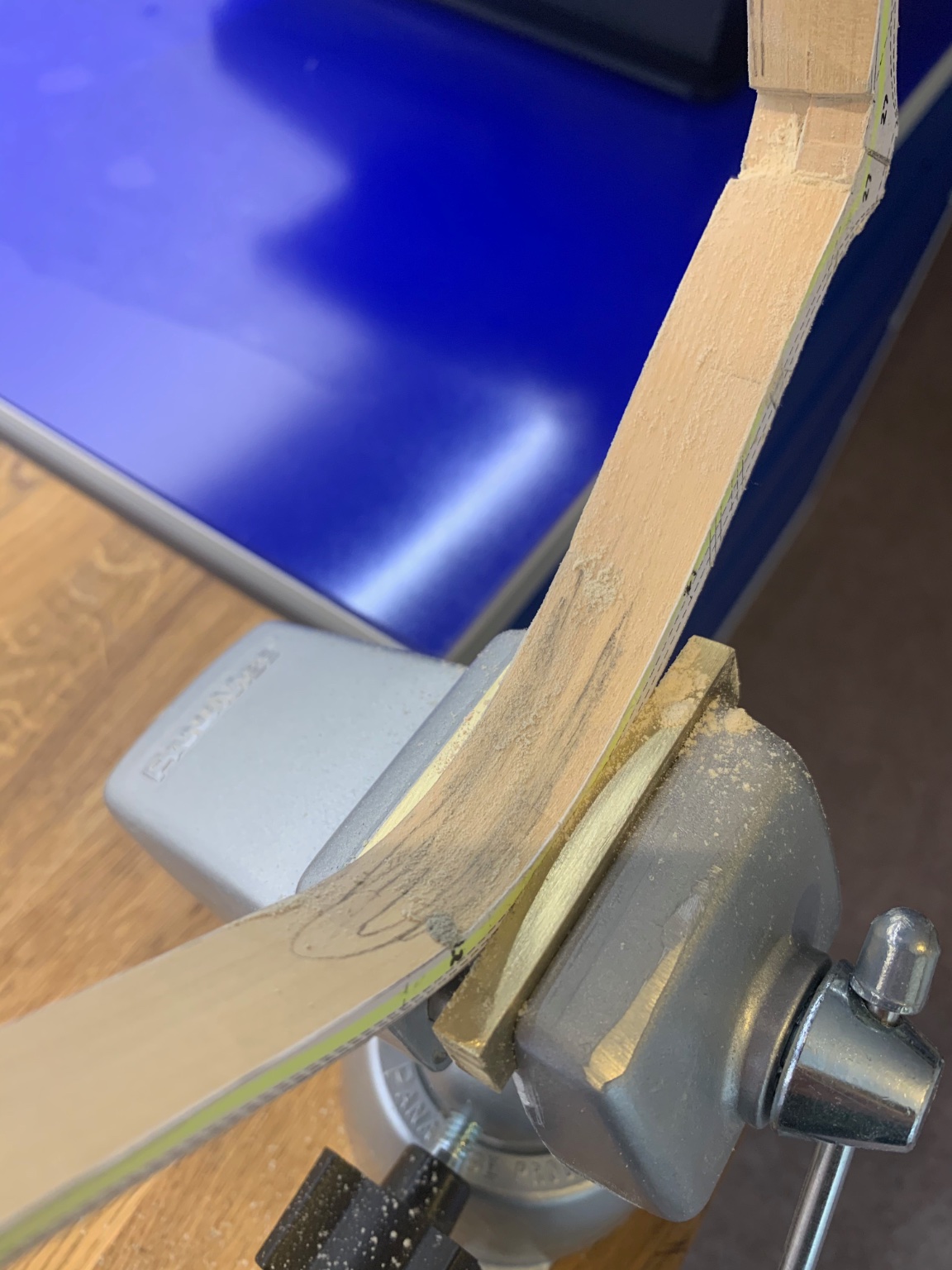
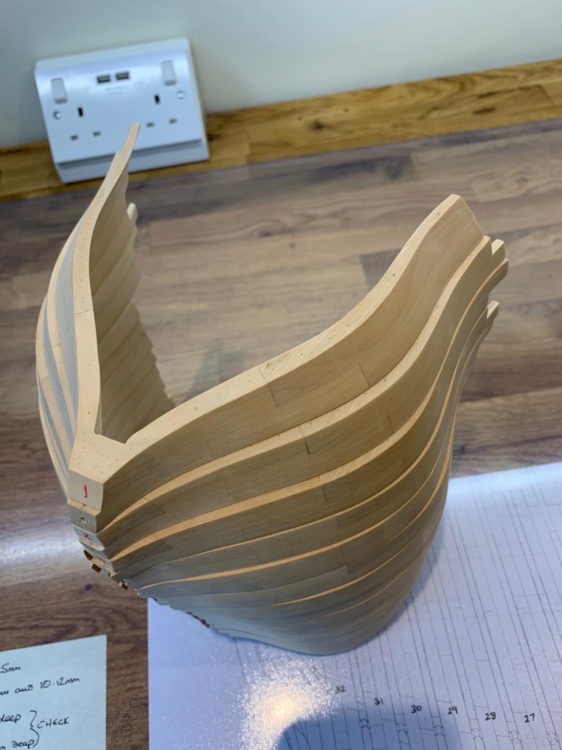
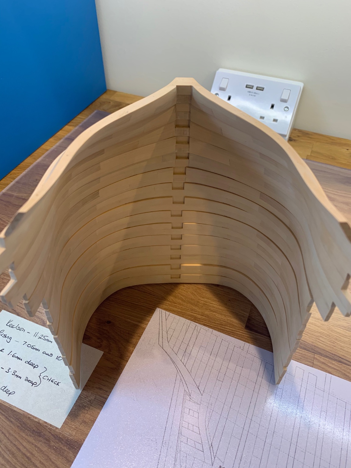
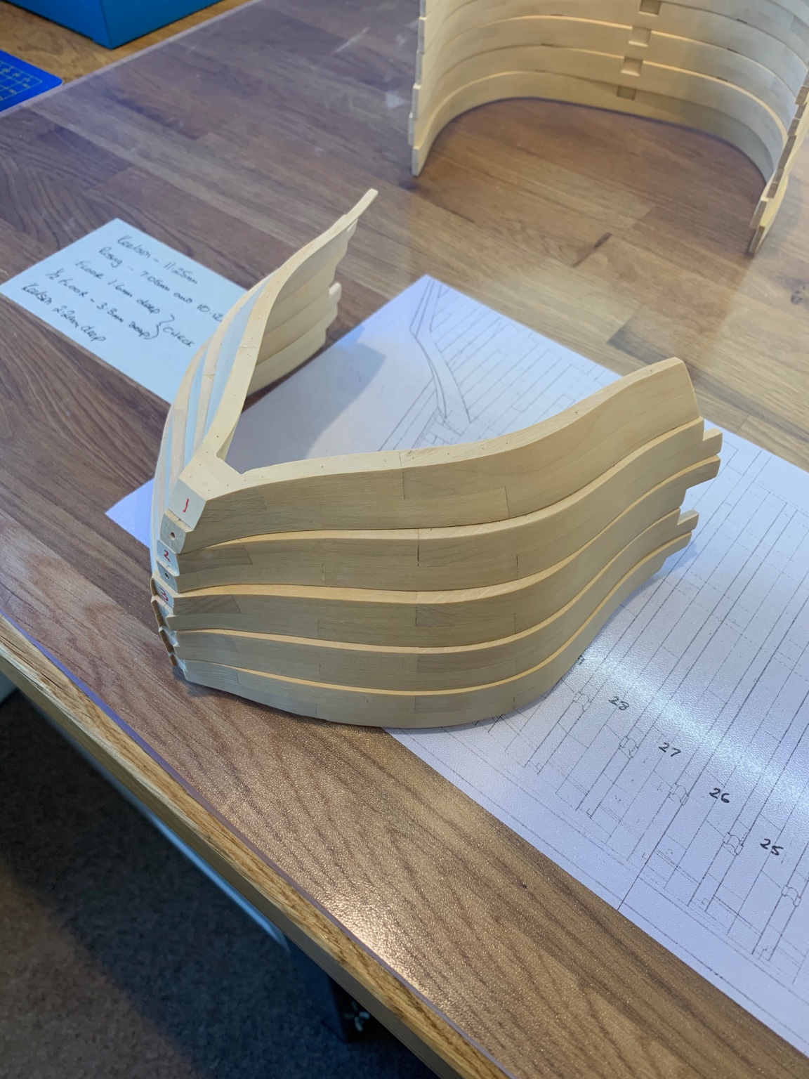
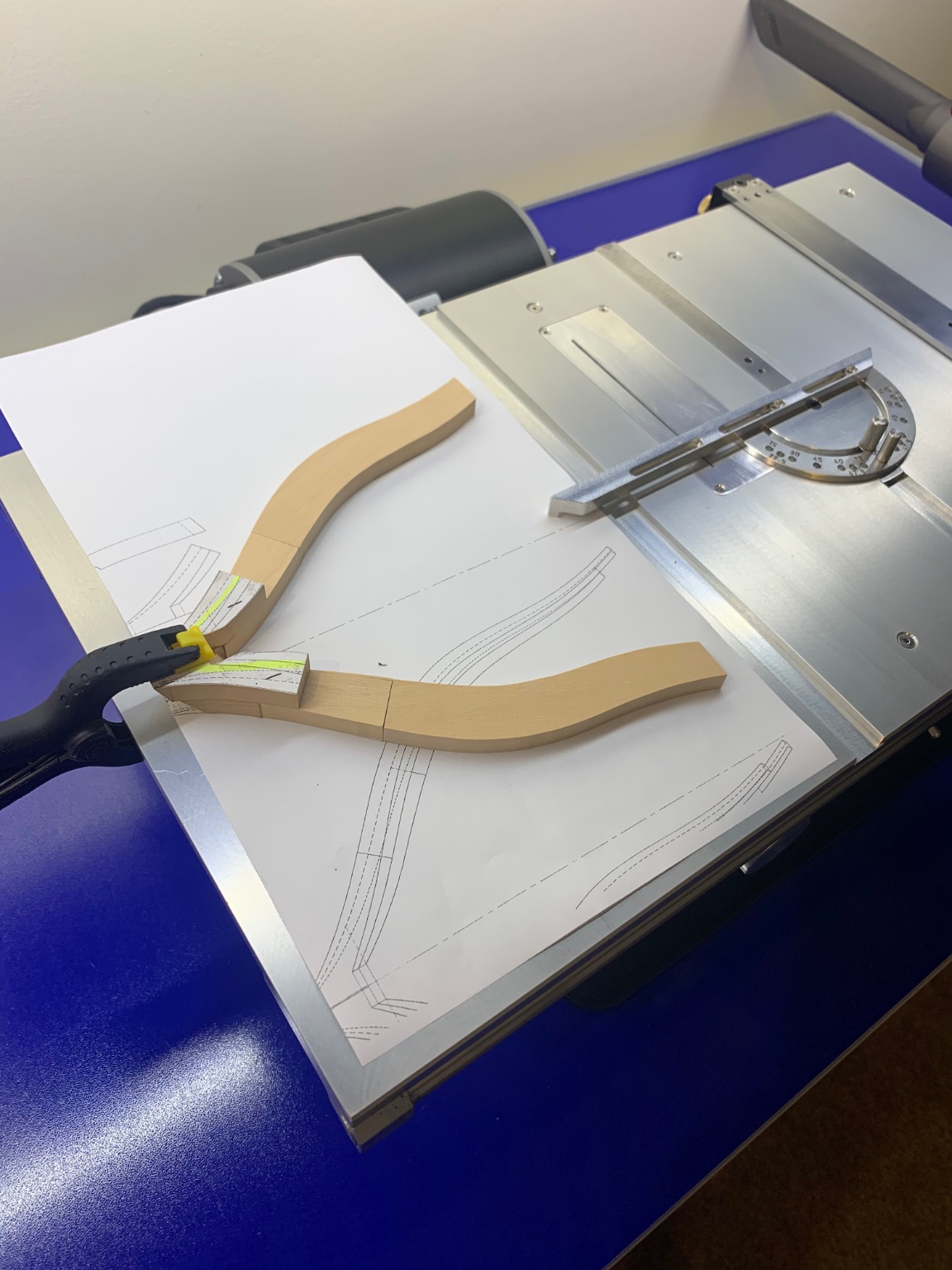
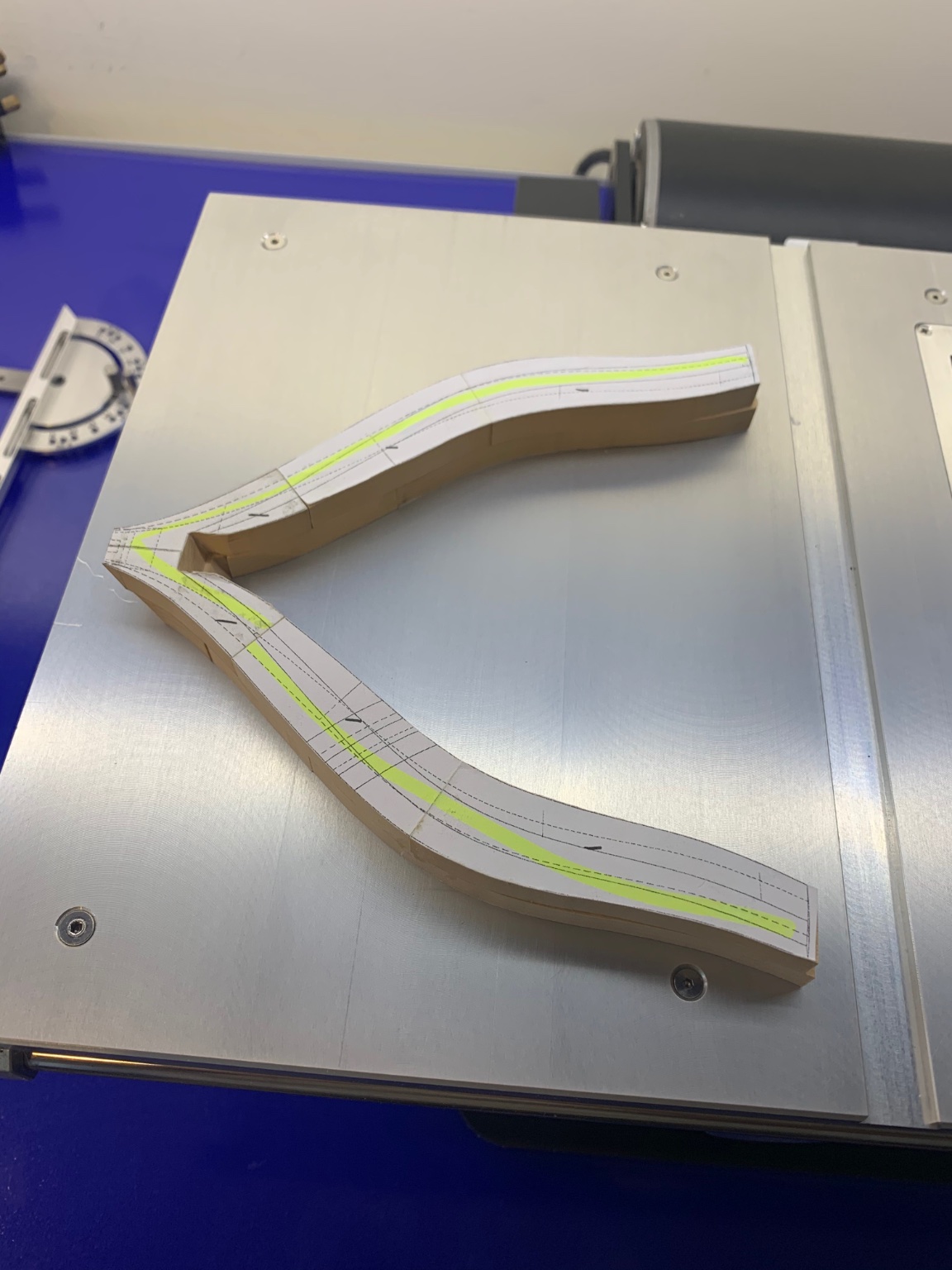
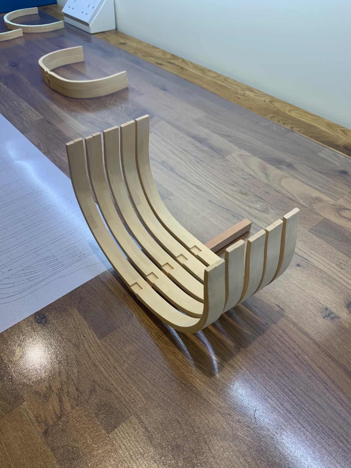
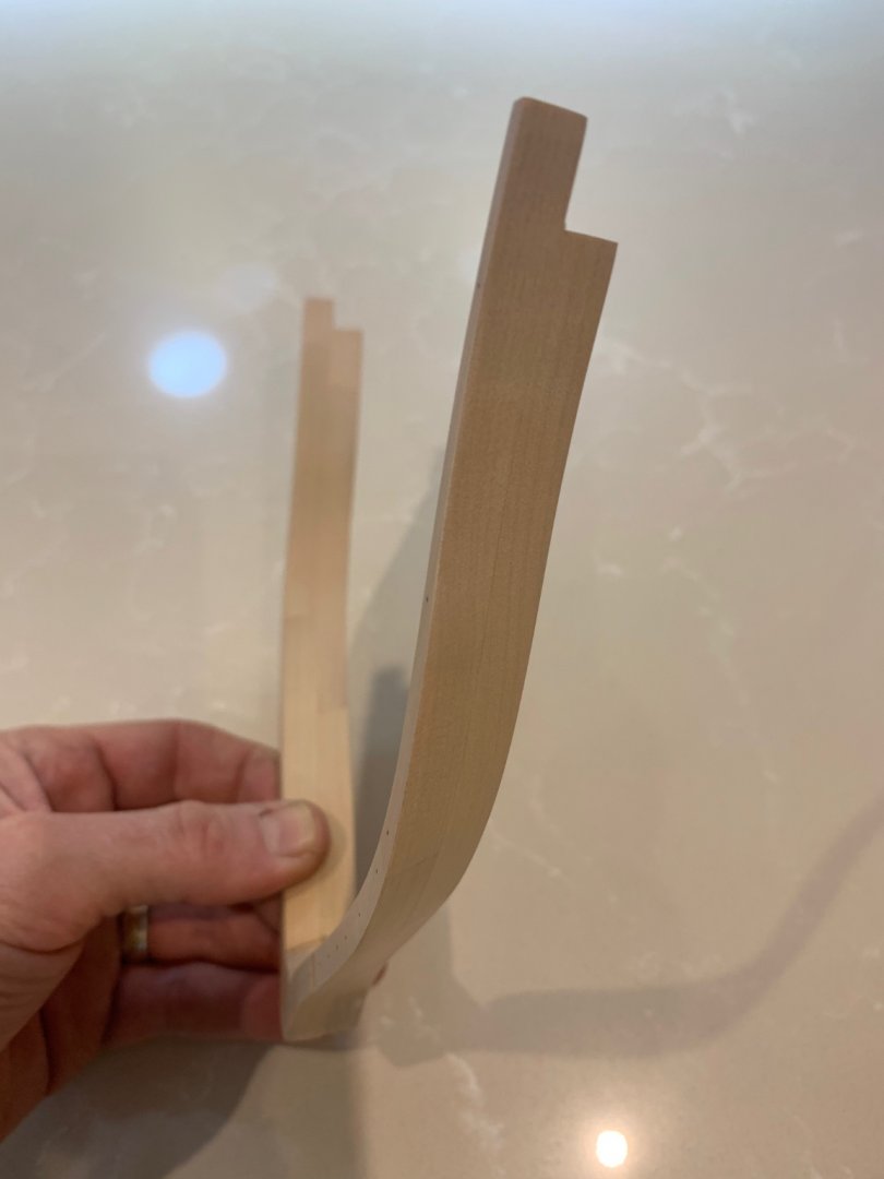
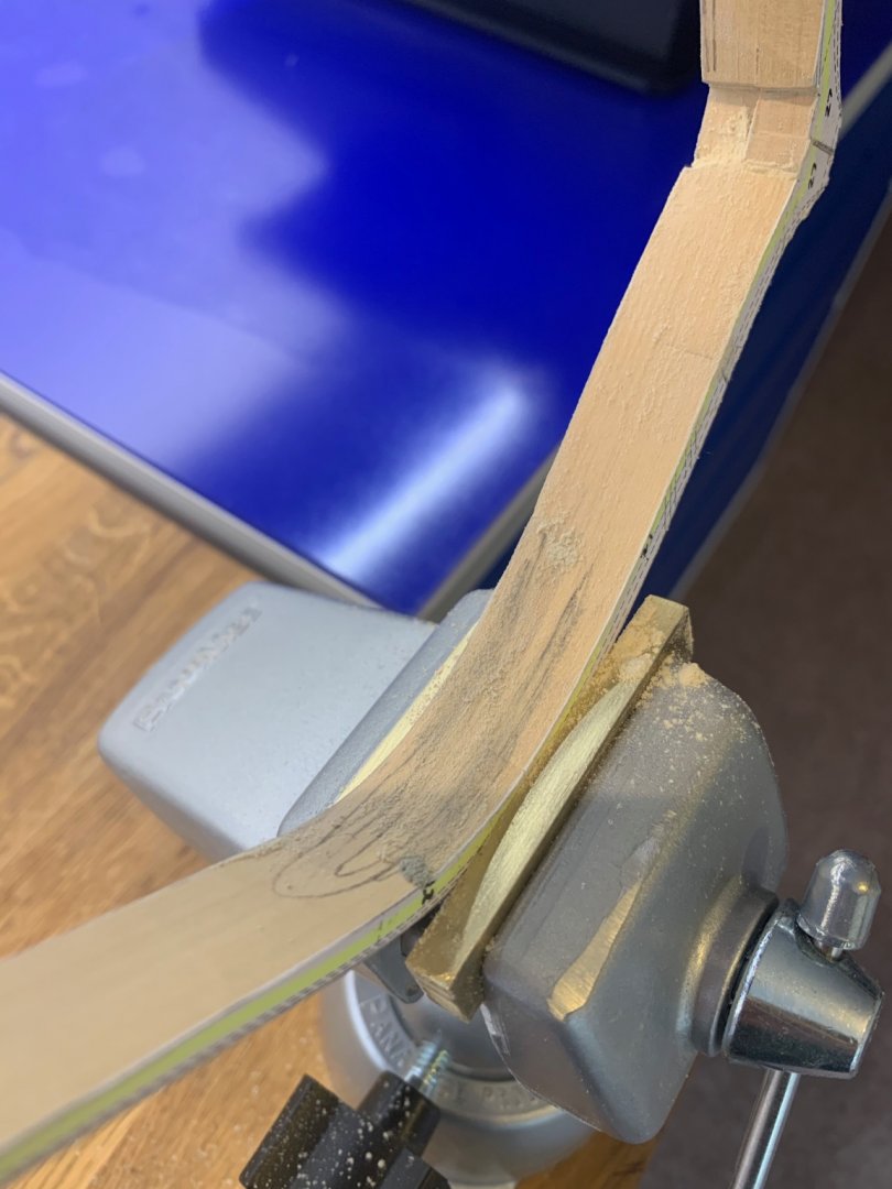
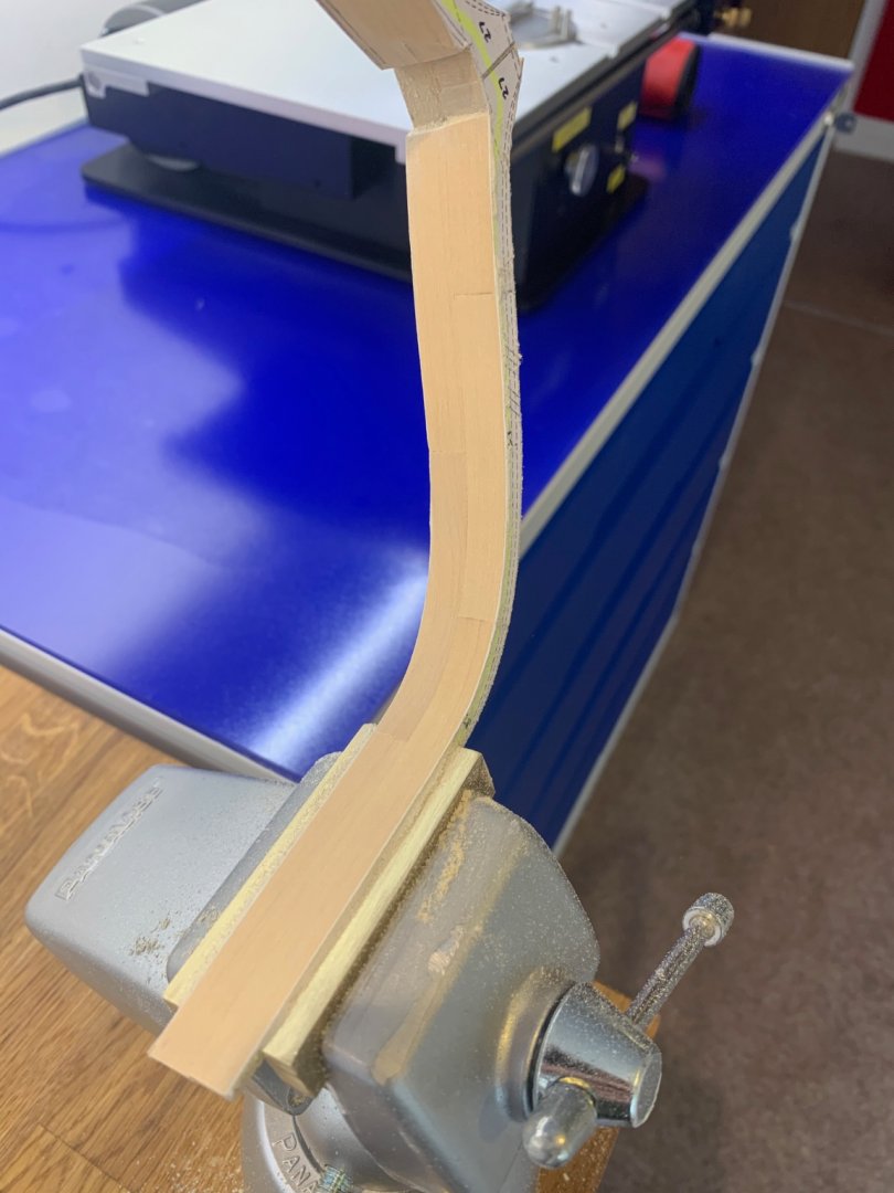
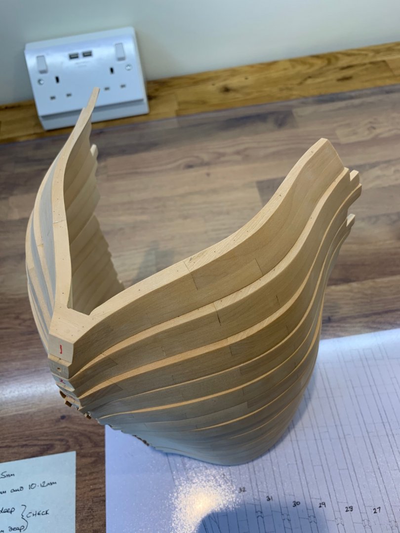
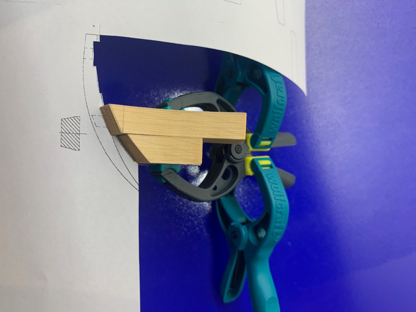
I've had a go at building the first of the 4 forward rising frames. This is frame number one and it needs to be spot on as all of the hawse timbers are attached to it later. I think if I get this one wrong it will have a lot of knock on consequences later in the build. Just out of interest what do you all think is a good wood to make tree nails from to complement Castello? Bear in mind that I will need to source it in the UK and I quite like the subtle look. I do have quite a good stock of pear and mahogany but I would very much appreciate any advice. I used a photocopy of the plans to workout and check the angle where the frame meets the rising wood. There's also a lot of material to remove too to get the bevel. I must also thank Barkeater as he helped me to understand the drawings of the rising frames as I just couldn't see them until he explained - cheers mate!

-
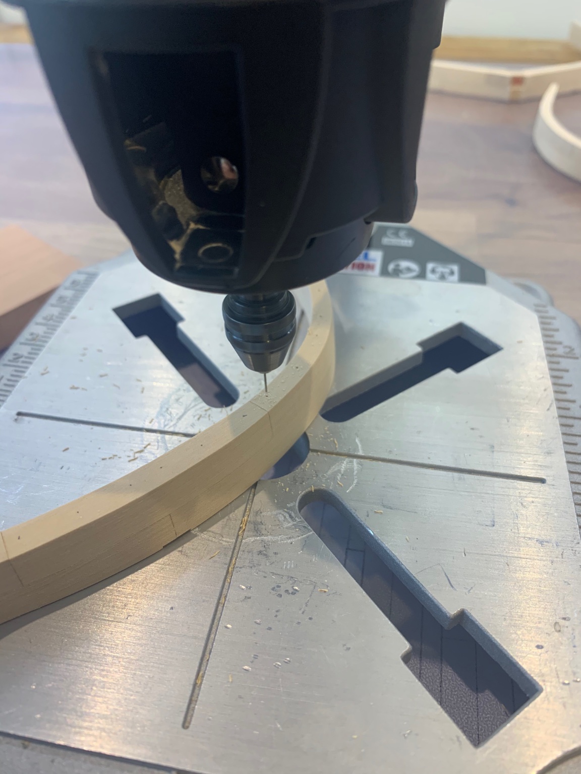
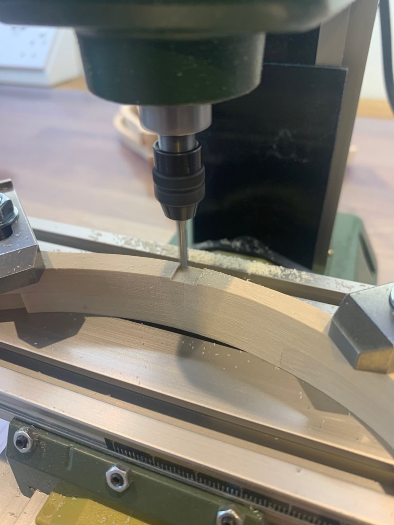
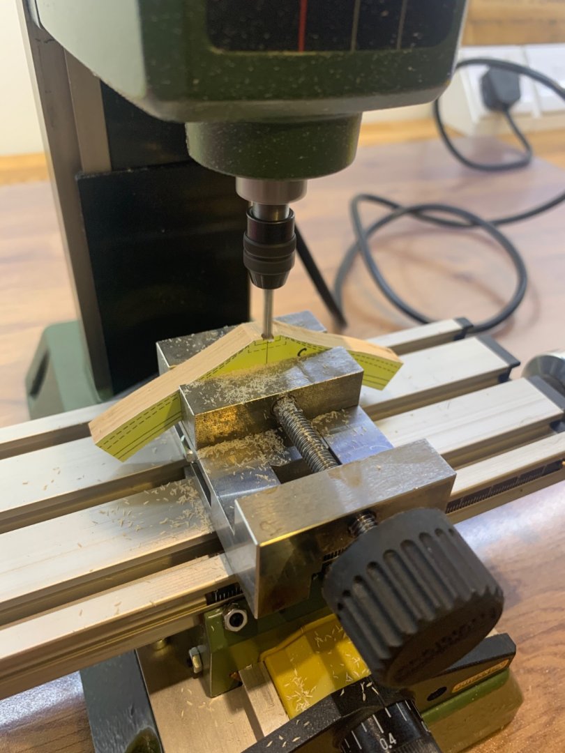
Hi G.L. and thanks very much I think that they are OK as these are the first frames I've ever made and I'm learning every time I make another. To make the cuts I have a Proxxon ML70 mill which is a nice little machine. Its tiny but it does a pretty good job.
-
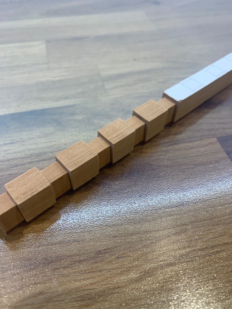
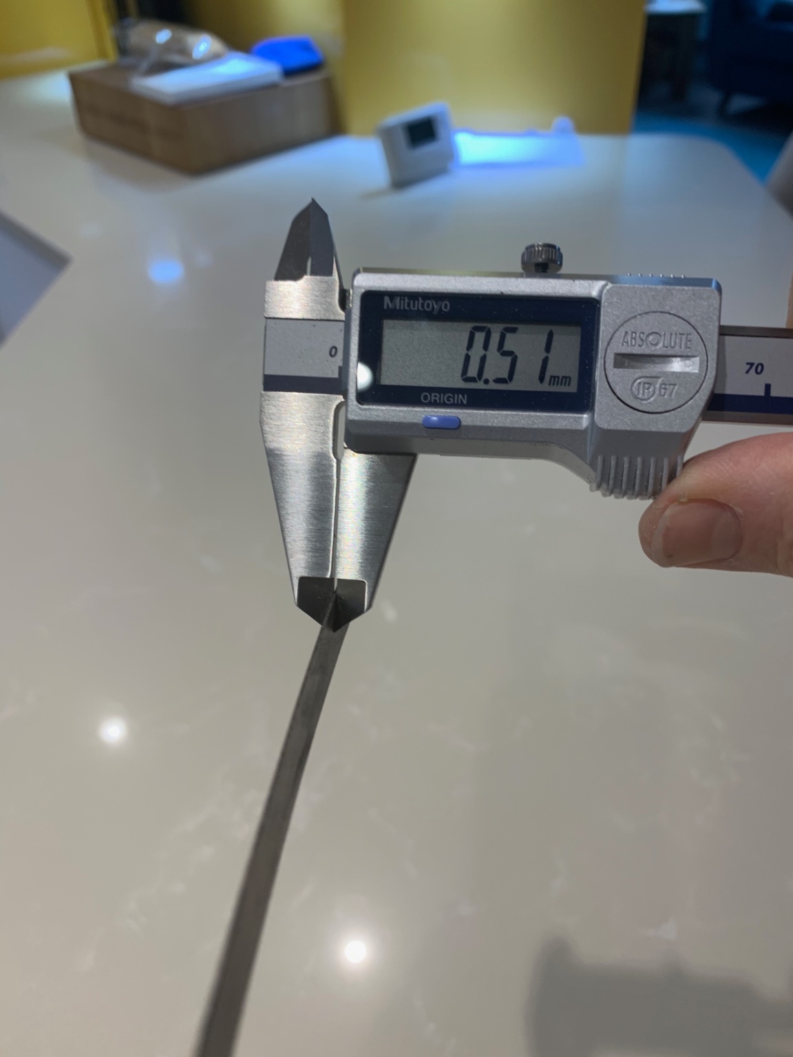
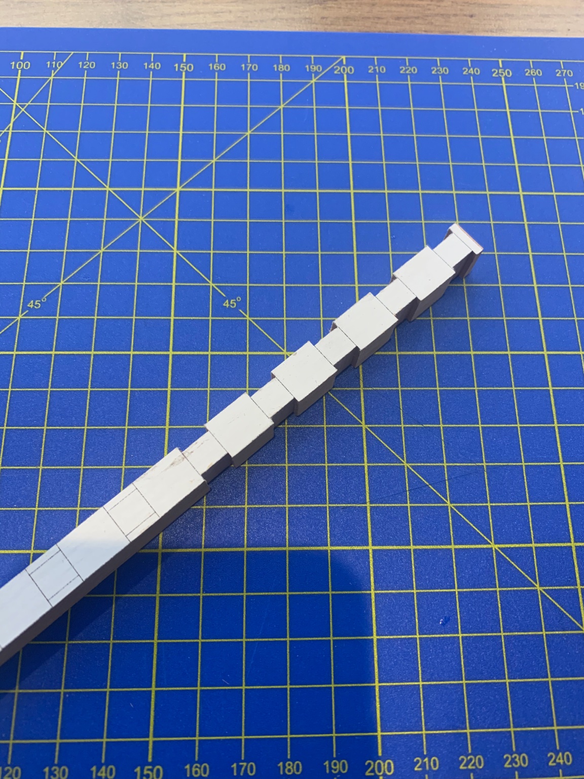
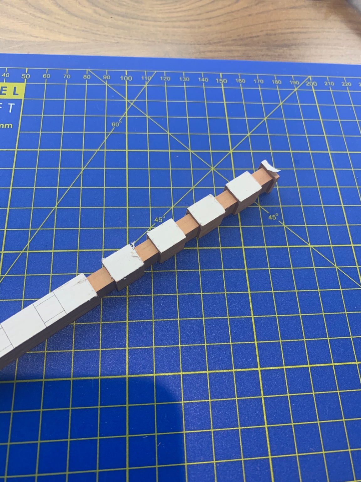
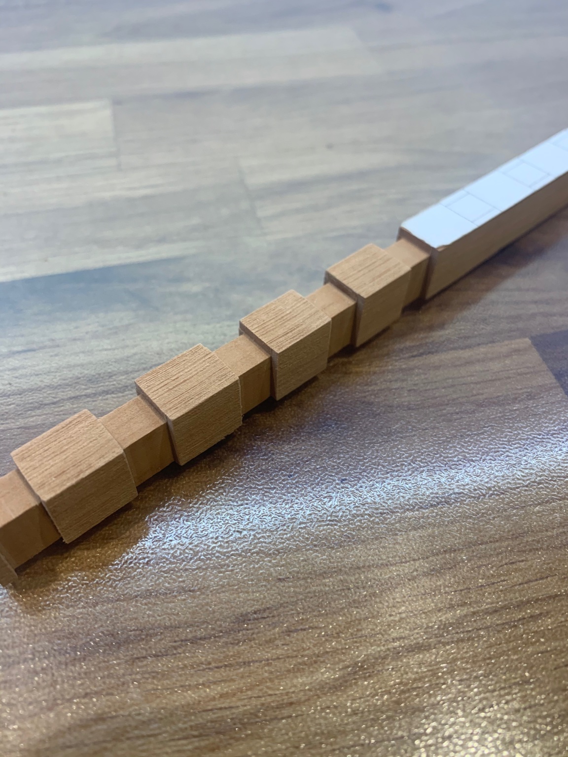
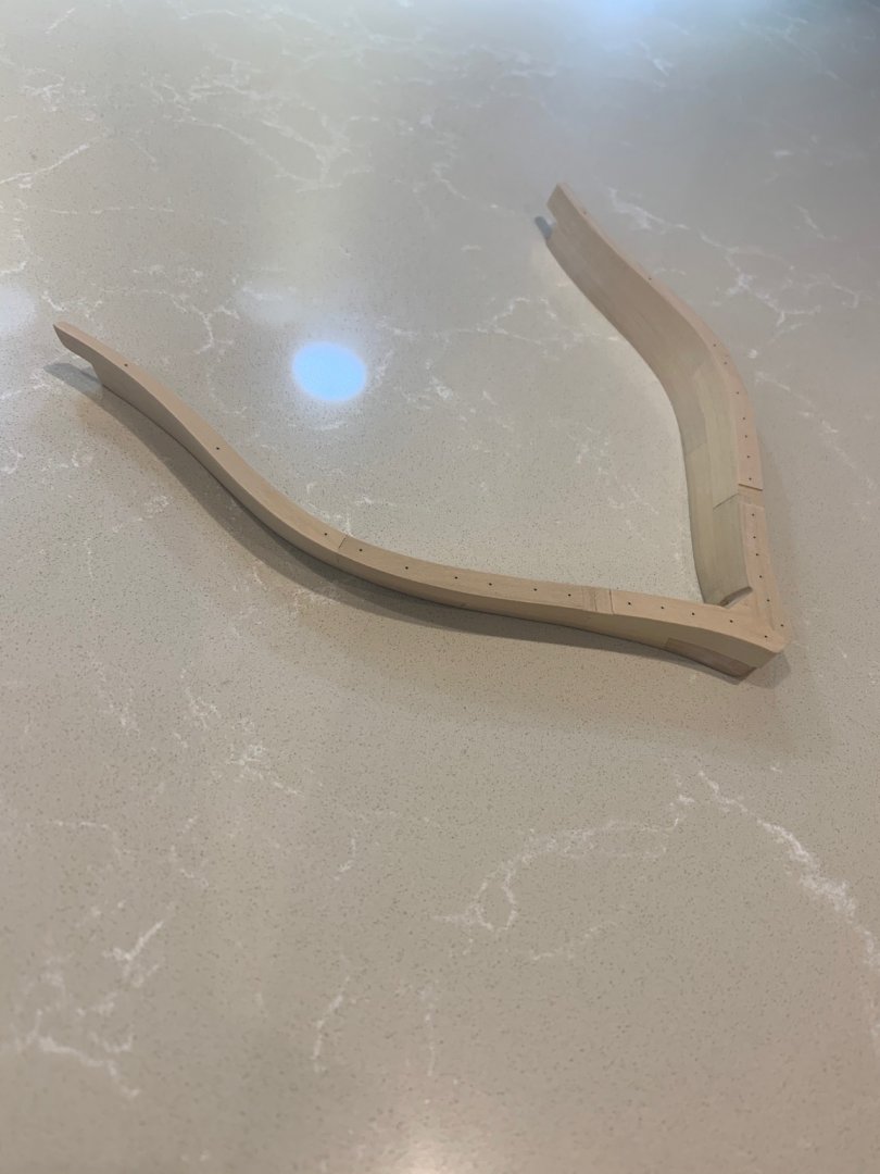
Next and to finish these frames for the time being was to make the bolts which help hold the frames together. I needed 0.5mm bolts to make them scale and I tried to make them out of ebony following the instructions by Adrian Sorolla. But I literally found my limit!!! I just could not replicate what he amazingly does as I really need a lot of them too. So I did the sensible thing and used 0.5mm carbon fibre rod instead which I think looks great. The instructions are clear that there should be 3 bolts at every joint overlap so thats what I did. I also cut out the rebates for the lower chocks which space out the frames. Later once the hull is faired I can cut in the limber slots into them.


-
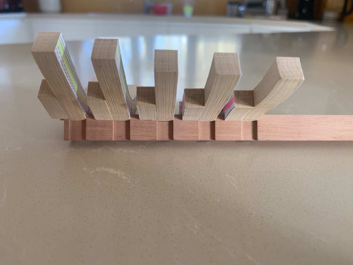
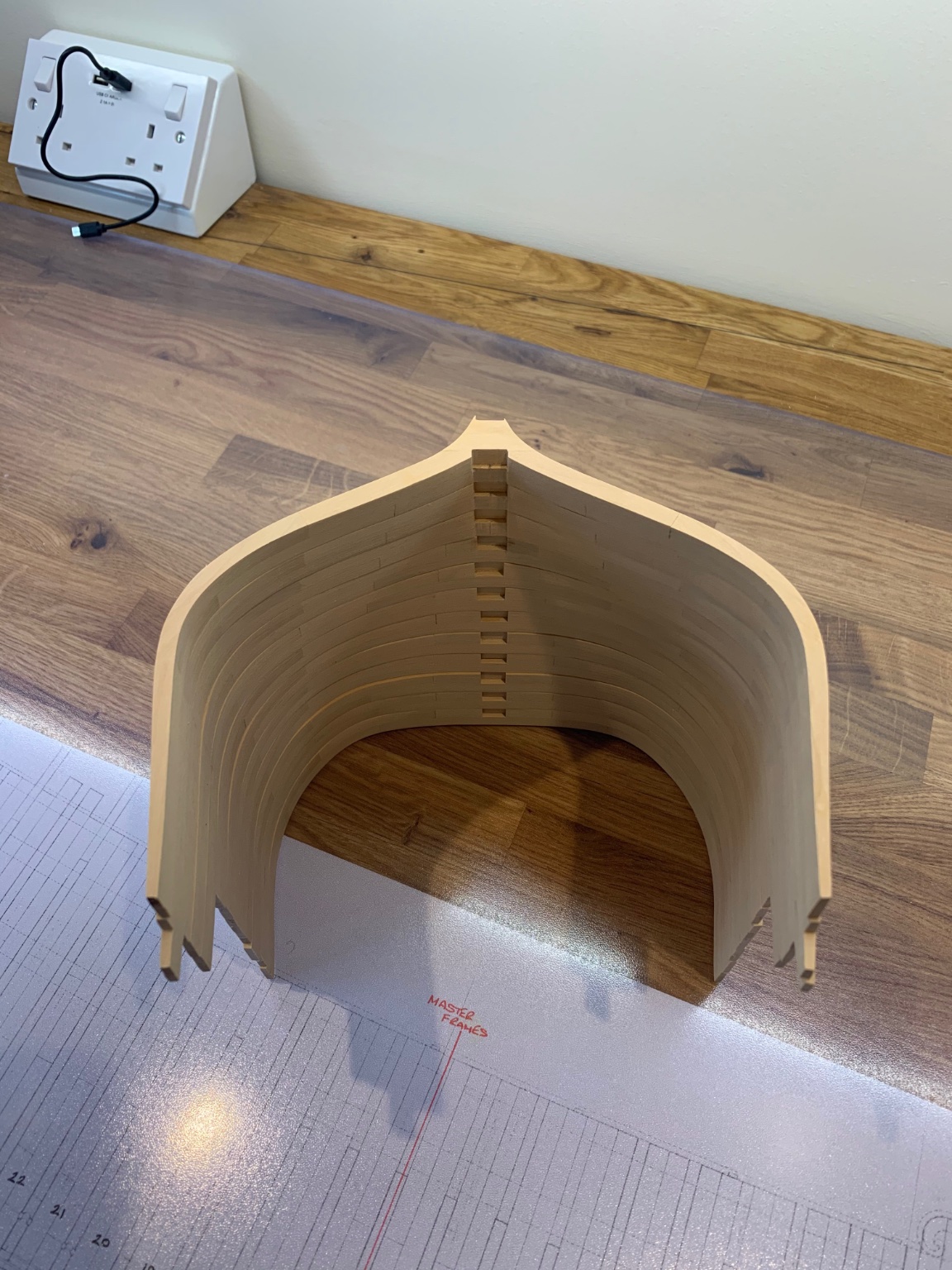
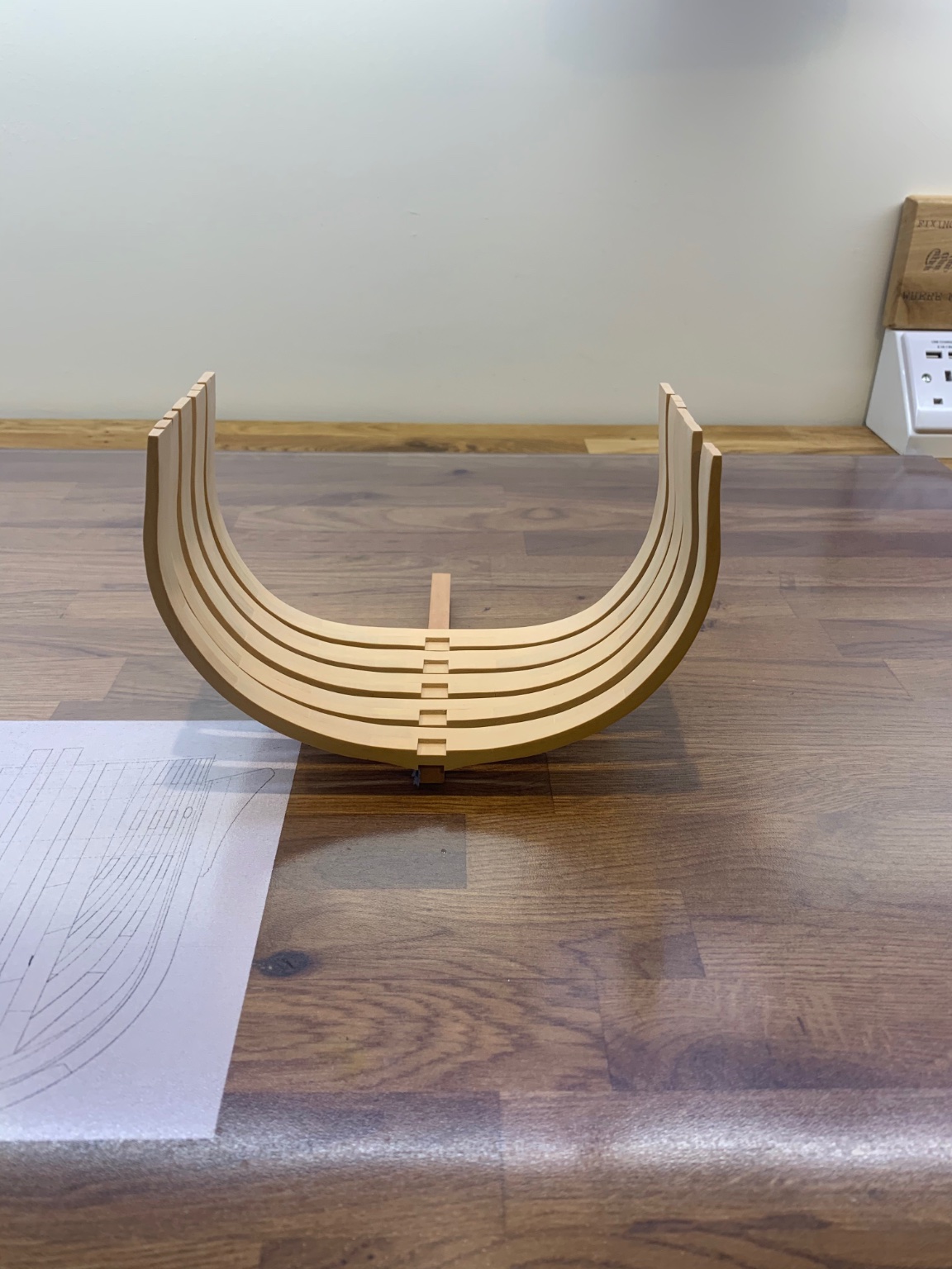
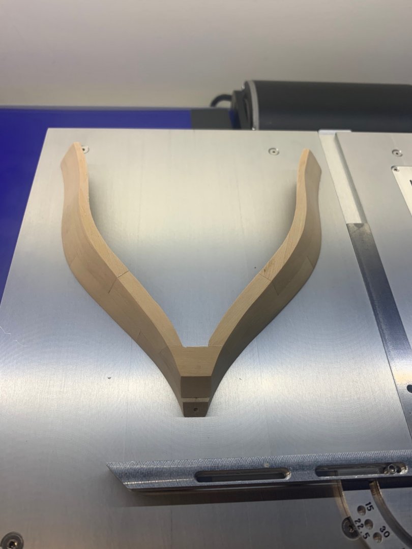
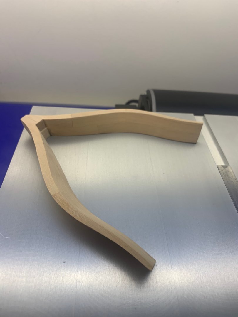
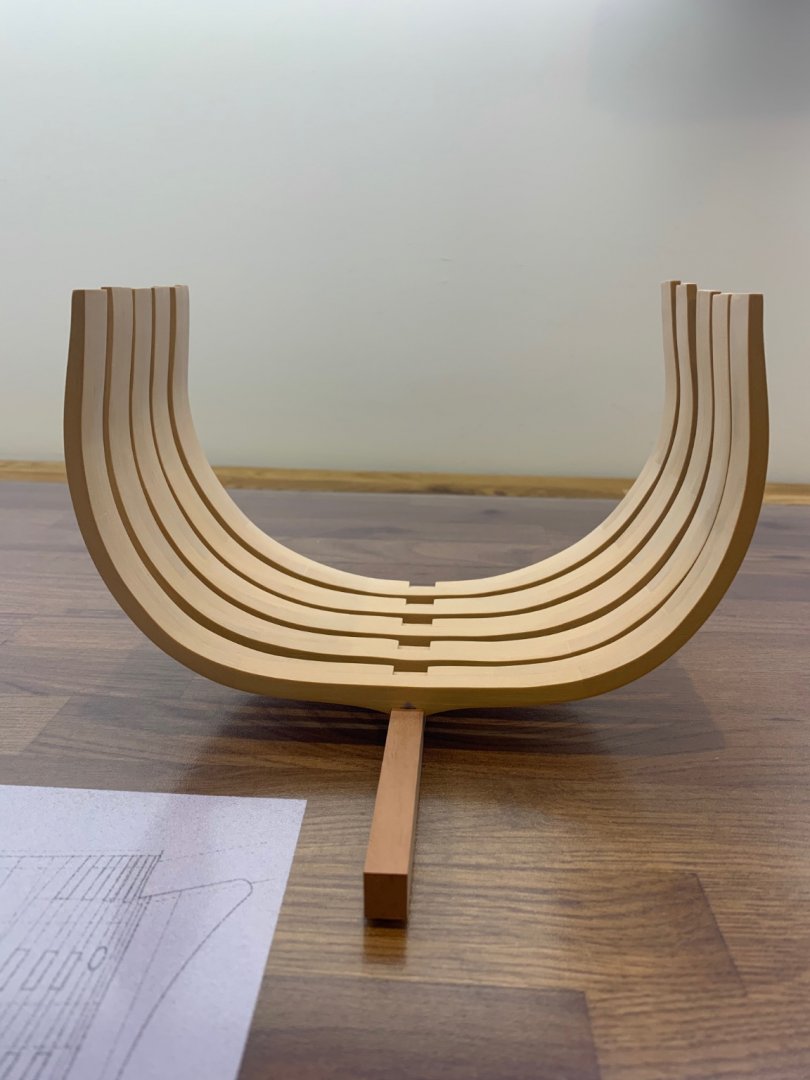
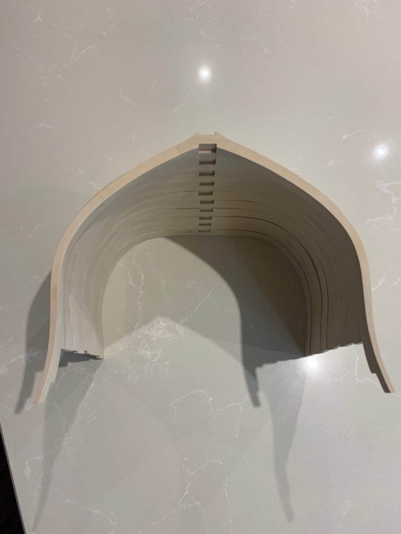
Assembled and bevelled forward frames which seem to have turned out OK. They match the plans which is always a good sign but I guess I will only find out of they are good when I start assembling them. I have to say that bevelling nearly 16mm wide frames means removing some serious wood!


-
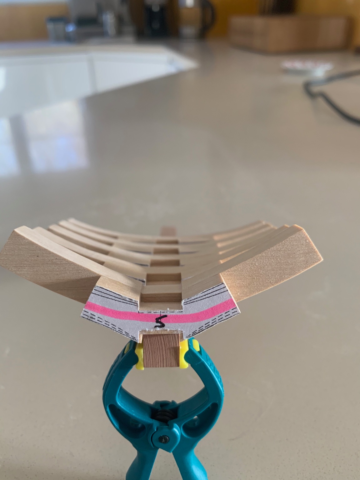
Next was to make a small piece of the rising wood so that I can glue the floor timber and the cross chock together. I would love to be able to say that my first frames went together with no issues - but no! I had sanded them far too much and had to make them again. Its not a problem I'm in no rush.