No Idea
-
Posts
1,036 -
Joined
-
Last visited
Content Type
Profiles
Forums
Gallery
Events
Everything posted by No Idea
-
 Thats really nice work Mark I think that it will sand up very nicely indeed. I wouldn't worry about the time taken as it took me 10 months to plank my last build correctly.
 -
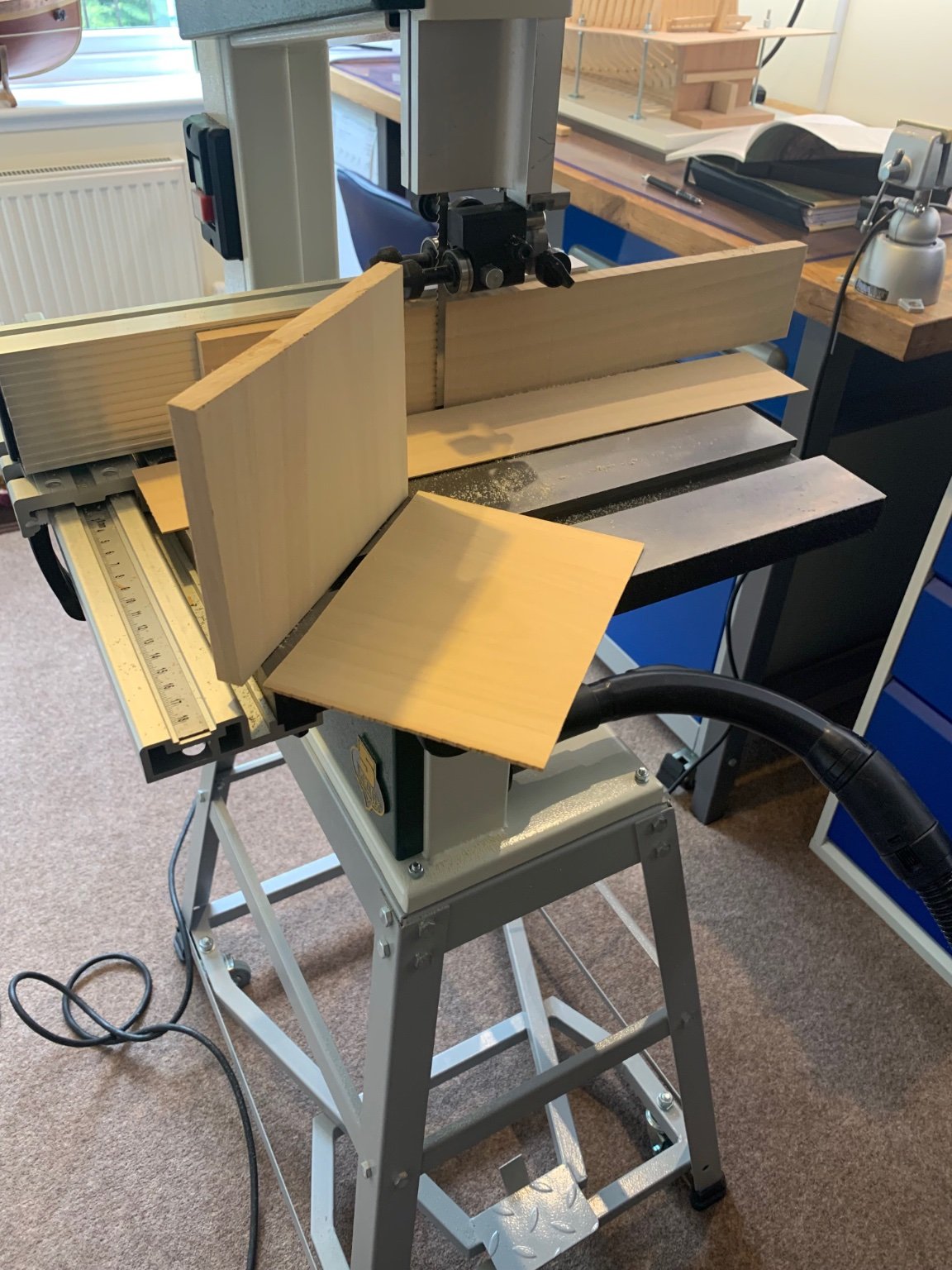
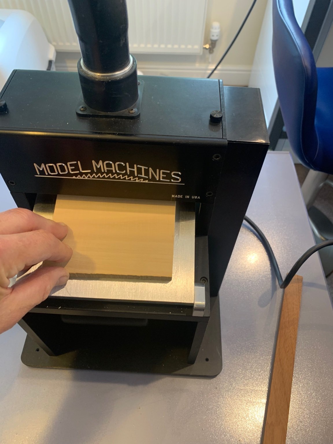
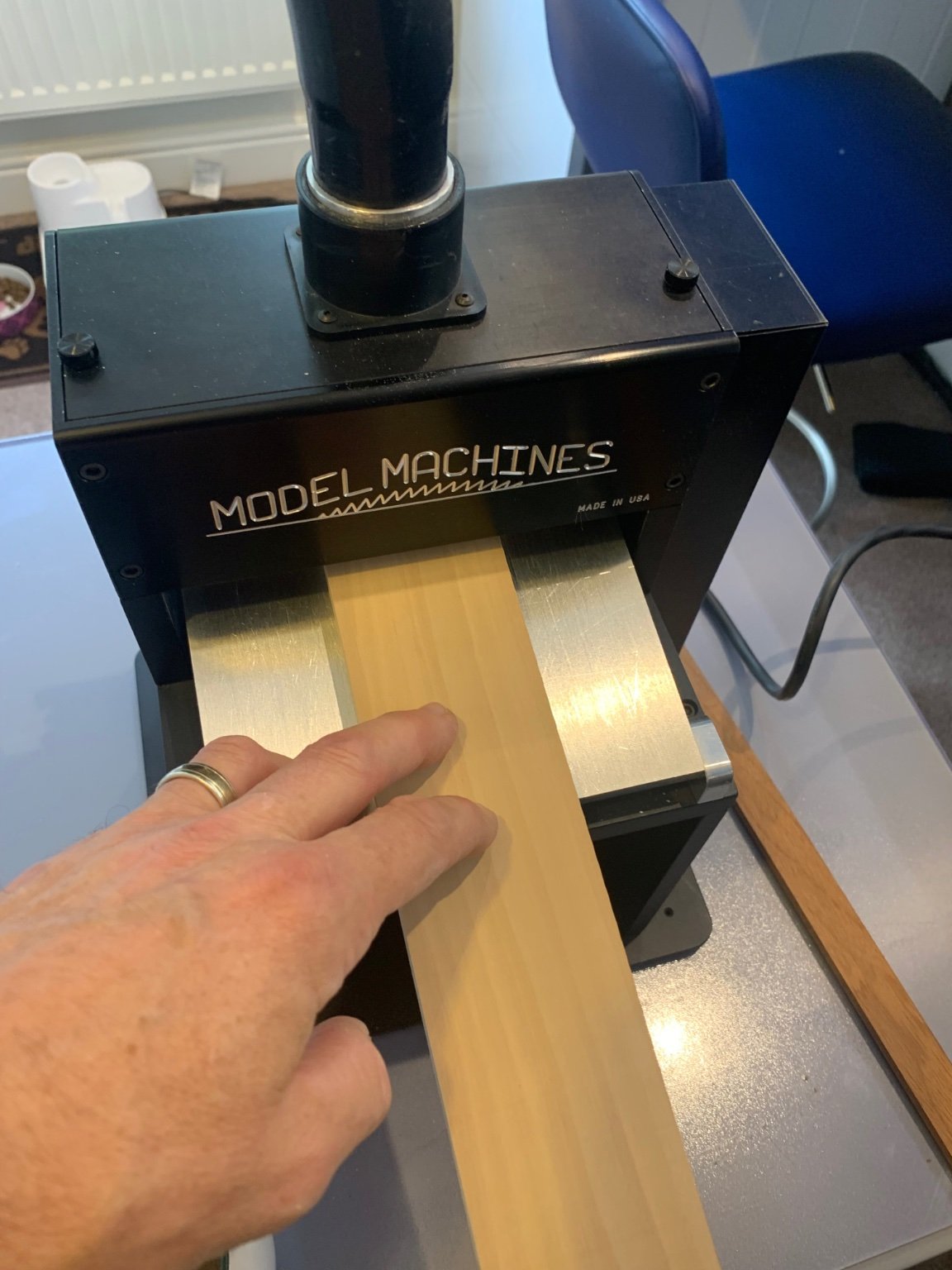
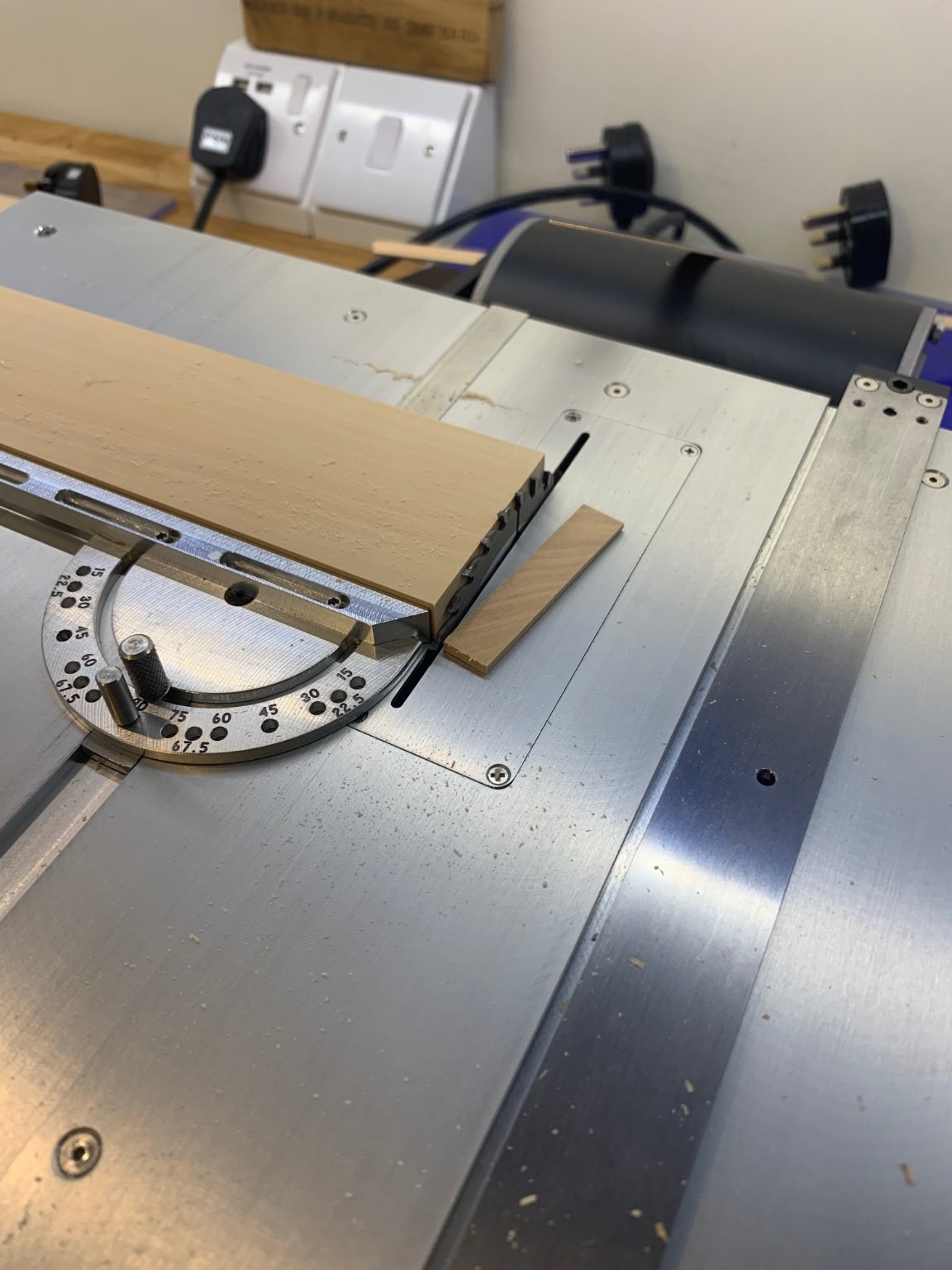
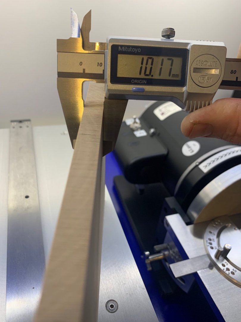
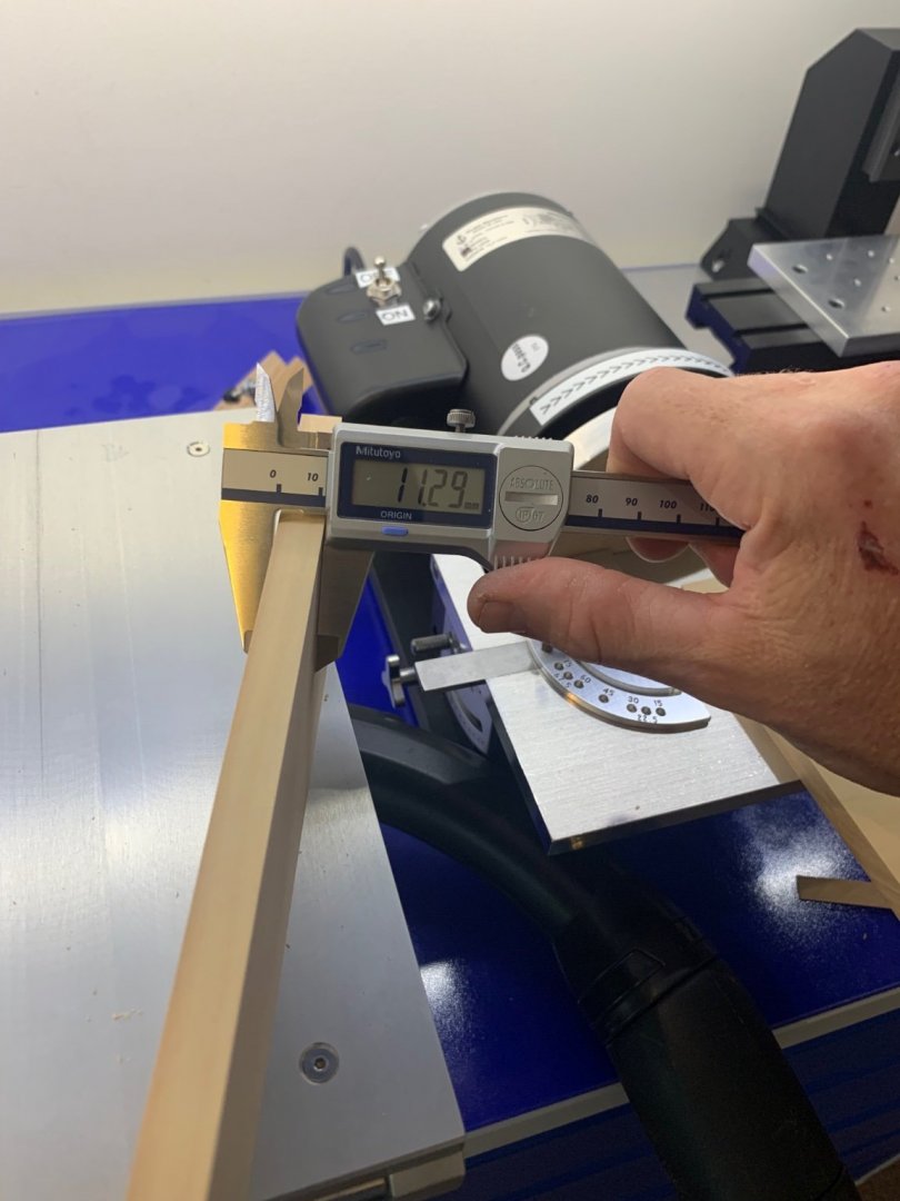
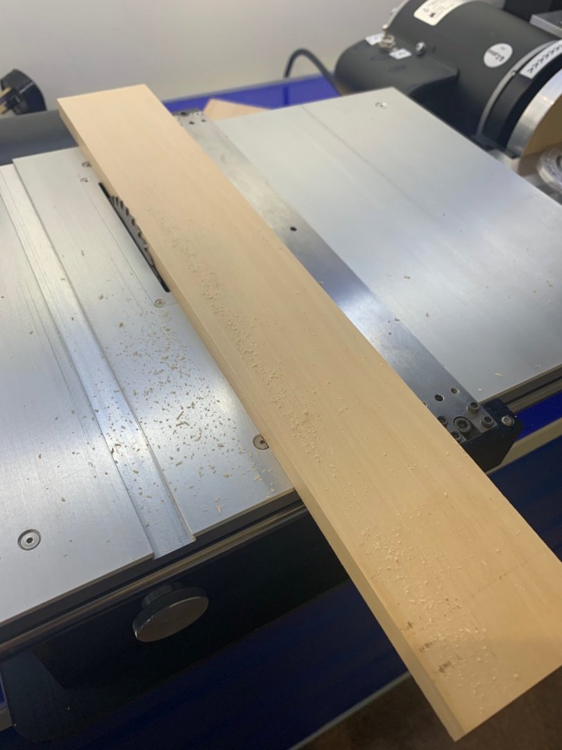
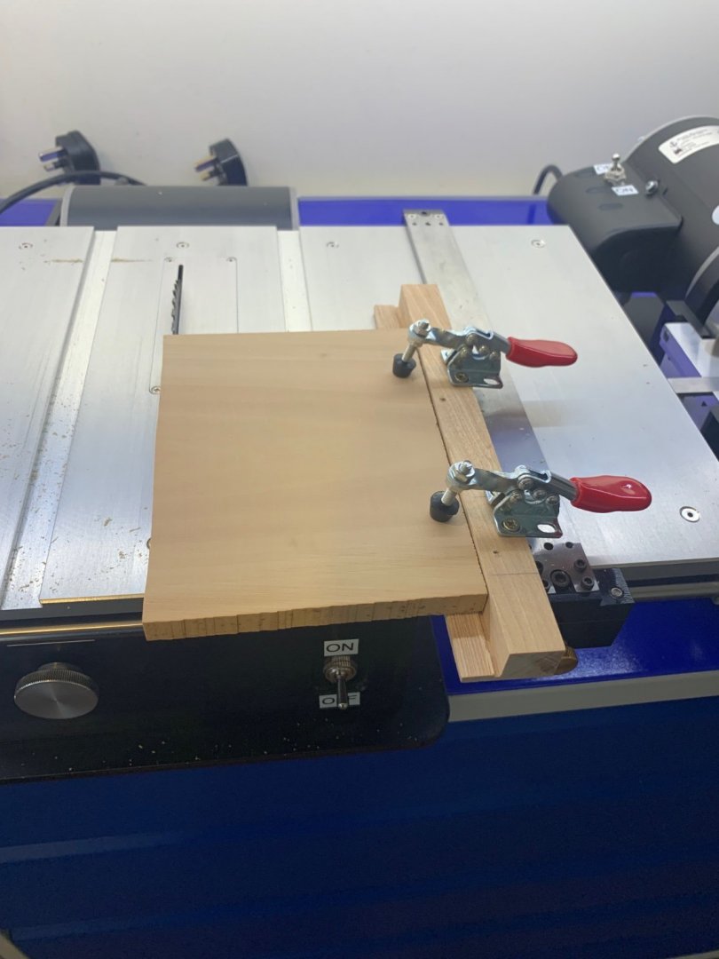
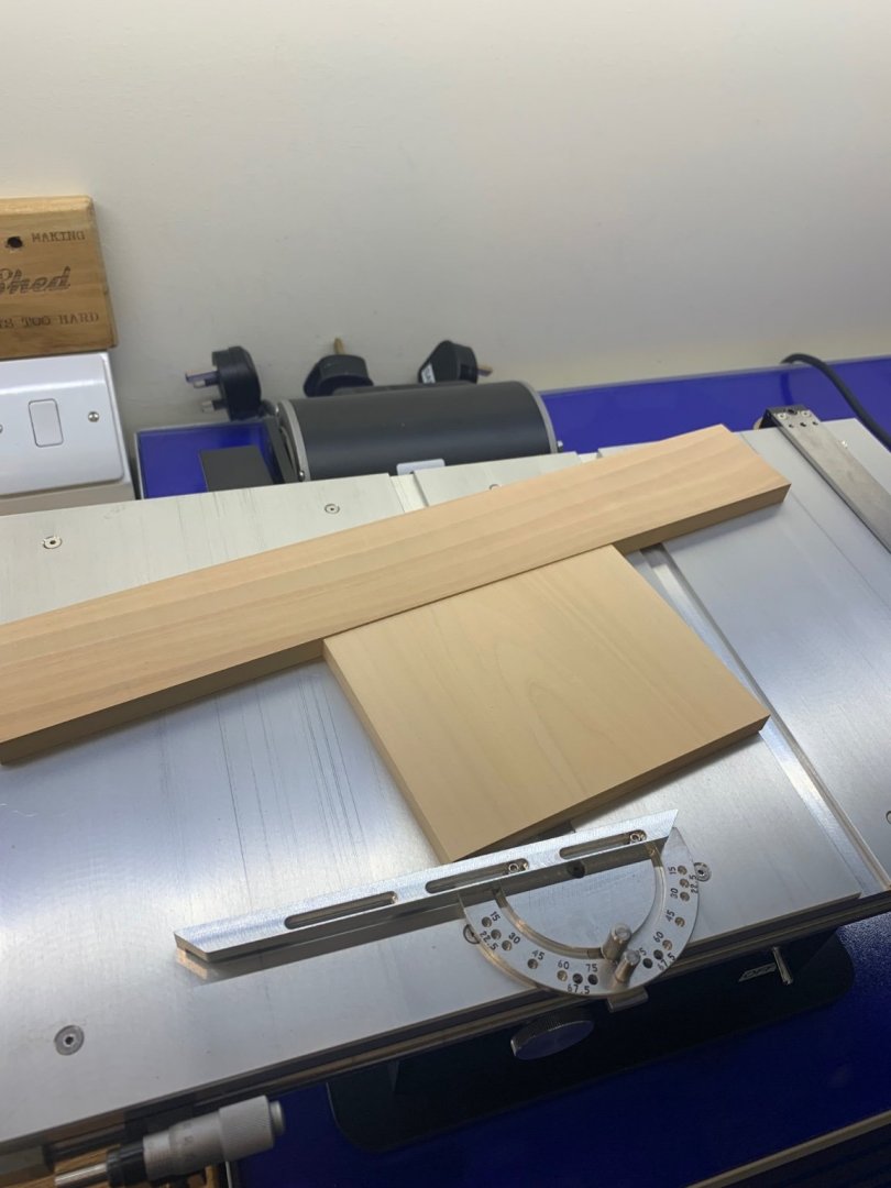
Thanks everyone for the tips - I'm glad to say that my hands are feeling much better this weekend 😀 I can't actually do any making this weekend as I forgot to go the the printers and get my plans reproduced for the keelson. I'm no good at drawing or tracing so I'll leave any machining to next weekend when I have a good set of copies. My wife has volunteered to sort this out for me while I'm away at work next week. I've noticed on a few build logs that people would like to see more posts about how things are done by the builders themselves. So today I prepared the wood ready for next weekend. The scantlings tell me that the keelson is 270mm thick and that the stemson and sternson are 243mm thick. So at a scale of 1/24 I need two pieces of wood the first being 11.25mm thick and the other 10.125mm. This is a big model and very wood hungry so I needed quite large pieces of wood to start with. The material I chose was just over 13mm wide so the first thing I needed to do was bring this thickness down on the bandsaw. I machined one piece down to roughly 11.5mm and the other to 10.5mm. Can I just say at this point I'm not going to talk about workshop safety at all. I trust that everyone looks after their own fingers and eyes appropriately. In all of the pictures the machines are stationary 👍 Next they were run through the thickness sander and I only needed to use fine grit paper as I didn't need to take that much more off. Then I ran them through the table saw to give myself nice straight edges and also make them square. If like me you have one piece that has no straight edges, just make up a simple sled using toggle clamps and voila its sorted. So now I have two pieces of wood at the correct dimensions ready for when I get my plans next weekend. The time taken was about and hour to do this including the clean up afterwards. I hope that his has been useful to someone - Mark


-
Thanks druxey - I've just looked on line and found lots of bronze wool. I didn't even know that this stuff was available until then! In the past I've used fine scotch bright pads but I don't think that they will give the fine polished finish that I would like on this boxwood. I'll order some up and do a few experiments with it.
-
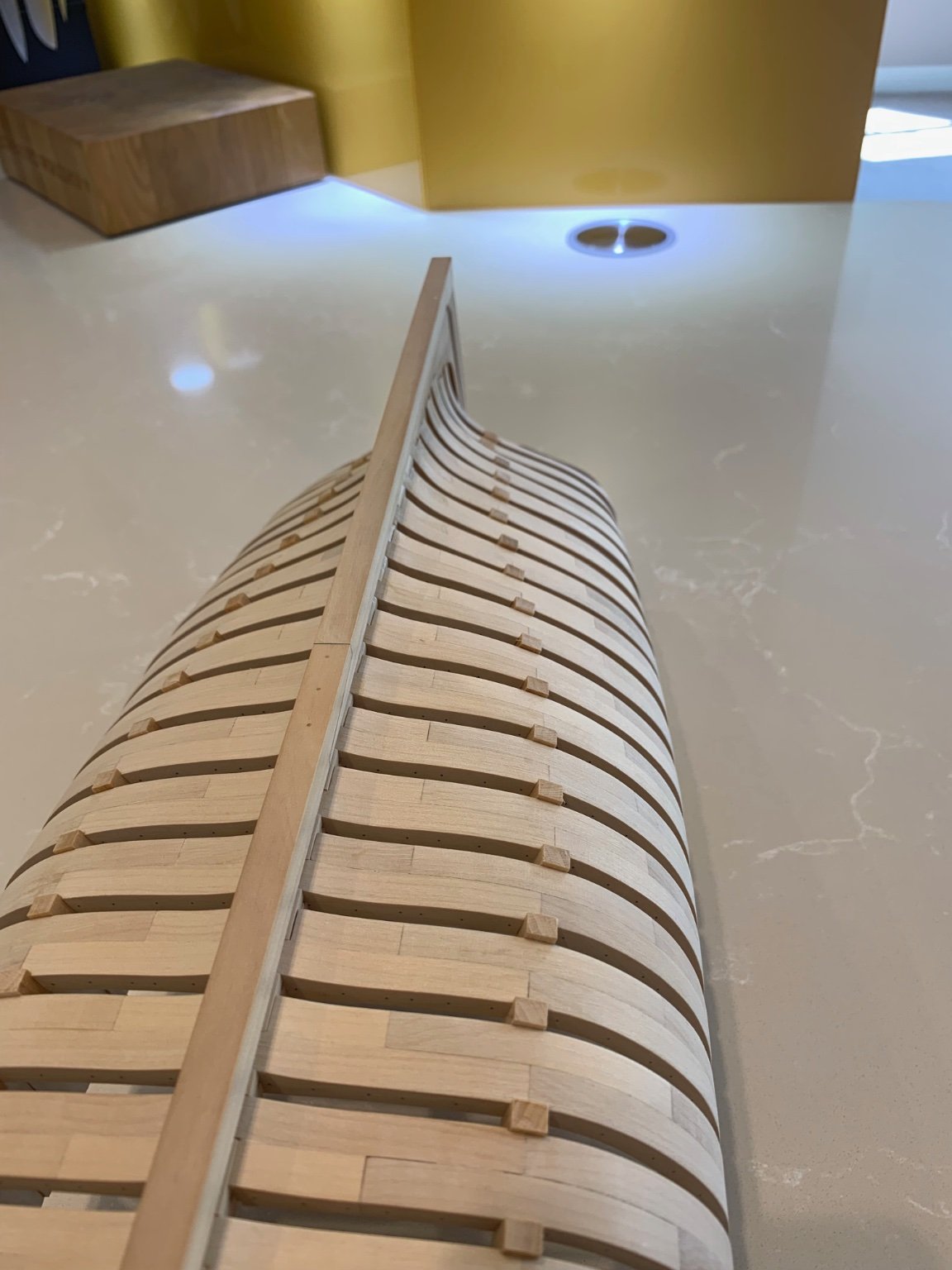
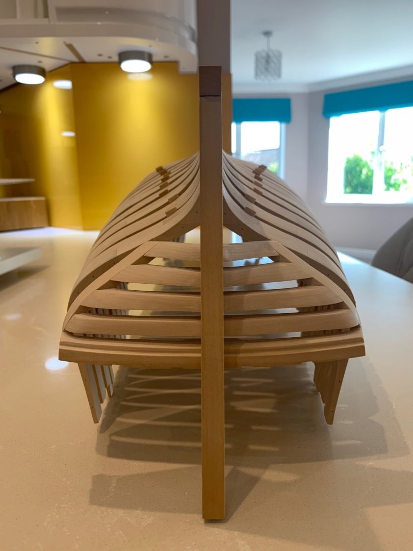
Hi Everyone I've now faired the inside of the hull which really does take hours. My hands and fingers are killing me they are so sore 😂 I wouldn't mind but I was using blocks too!!! I have learnt not to leave any frame chocks protruding too far into the hull; thats another one for next time too! I didn't have many places where I needed to remove too much material. It was more about lining the frames up correctly - please remember though I do have scale on my side as these frames are thick. How you builders do this at 1/48 scale must make the process so much harder and more precise in the first place. I have to say its a lovely job to do especially when you get down to some finer papers such as 320 and 400 grit. You can just feel that things are starting to be right - it's hard to explain. I've stopped at 400 grit as I'm sure that the interior is going to get a bit bashed around before it needs a final finish. I'm not sure what you all use for a final finish but I'm thinking wire wool is probably the way to go when I get around to that stage. The next job is to make the keelson and I will make a start on that tricky piece next weekend. Mark - BTW I think I should say thanks for all of the likes too its quite humbling to be honest.
-
Thanks druxey for the encouragement 👍 I know that my next build is at least a couple of years away so I can get lots of experience and advice in the mean time. The fairing of the inside is going well; in fact I think its starting to look really beautiful inside. I've been sanding for hours and I've got quite a few more before its done. I'll try and get some pictures up tomorrow but wow are my fingers sore from all of the sanding 😂
-
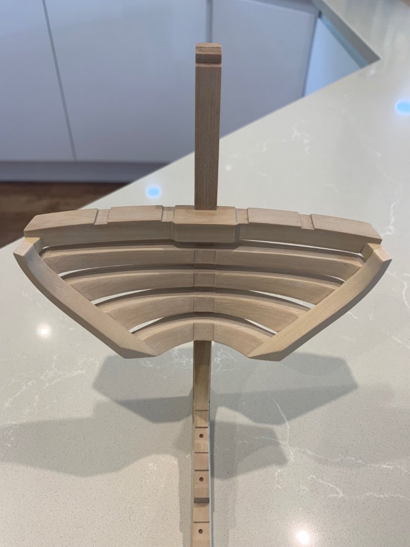
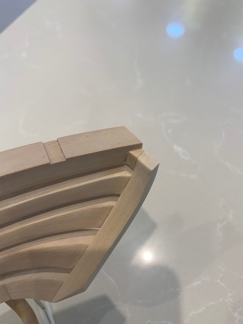
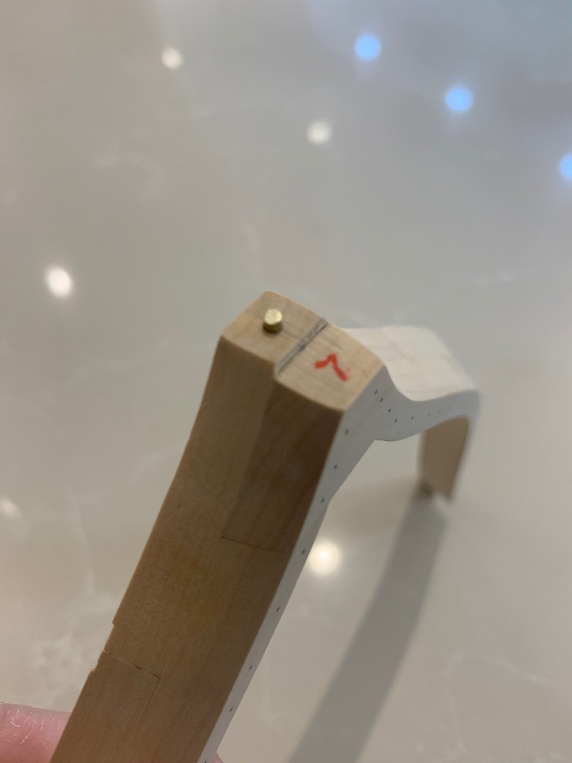
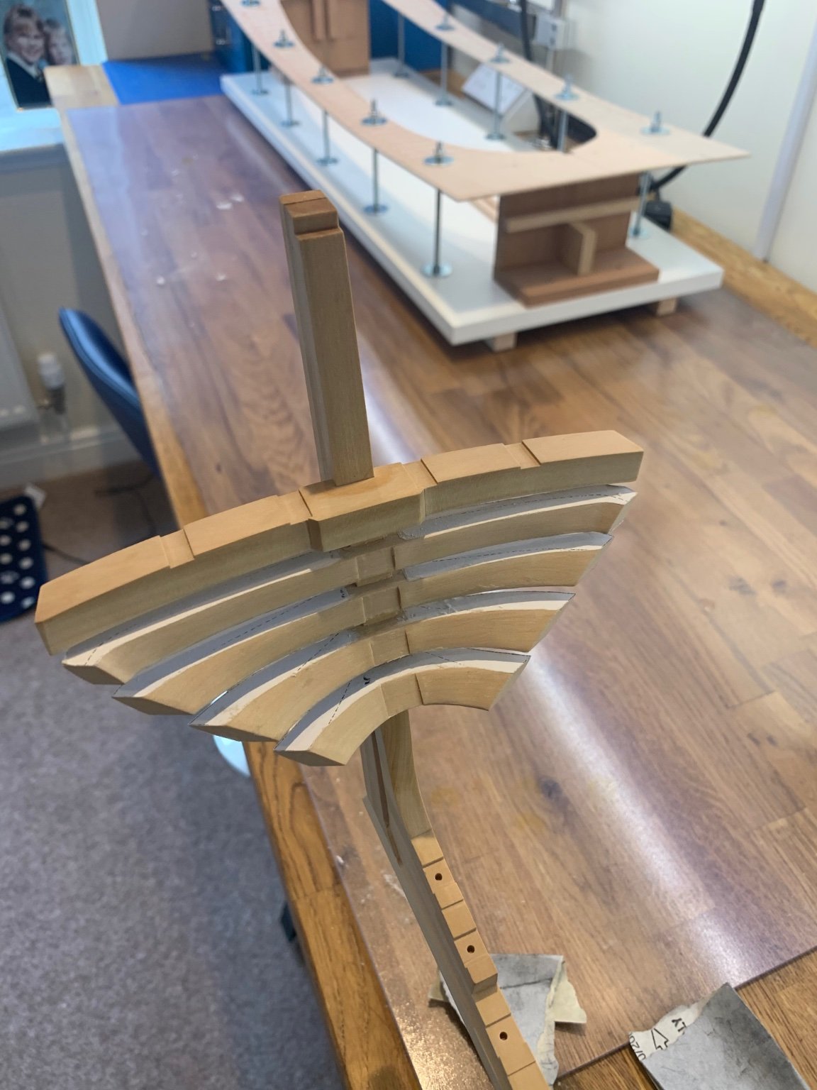
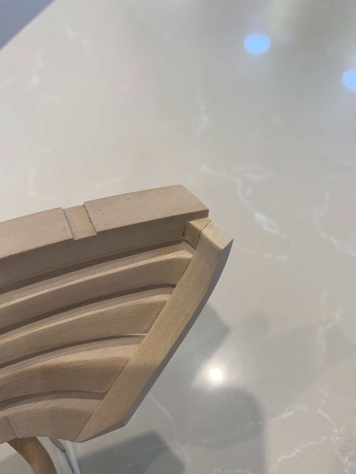
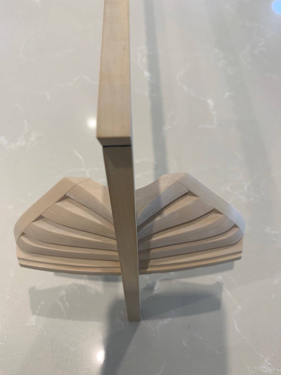
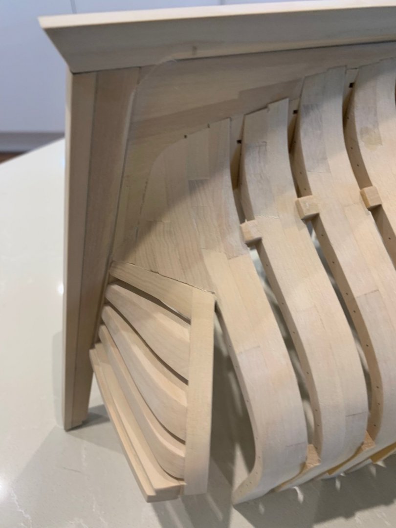
I've now roughed out this piece and glued it into place. It will get its final shape when I fair the outside of the hull. I'm not entirely happy with it but its my fault for not thinking ahead. A very small additional triangular piece had to be made for both sides to make the transition from the block to the sternpost smooth. I did have difficulty recessing the inside of the piece because it was difficult to hold due to its shape. In hindsight what I should have done was put a couple of screws into it where it wouldn't notice and then clamp onto the screws. They could have then been simply removed before gluing. I'll save that one for next time! I think my build will slow down for a bit now as my next job is to fair the inside of the hull. I think that this job is going to take quite a long time to get right but I'm looking forward to it. Once the hull has been faired inside I'll have a go at making the keelson, stemson and sternson. Cheers Mark


-
Hi Hubac's Historian, Mark and Greg; thanks for the comments 👍 I hadn't even made a wooden scarf joint until I started this build as my other two builds were both POB kits. Before that I had no real experience using wood. I did a tool room apprenticeship many years ago which was all metal work which I now see has stood me in good stead for model ship building. Everything back then had to be machined extremely accurately or it went in the bin which would not have pleased the foreman. This was before CAD or CNC so everything was made manually by hand. Would you believe that back then titanium was so rare that if we were given a small piece to machine, we had to collect the swarf and hand it in at the end of the working day 🤣
-
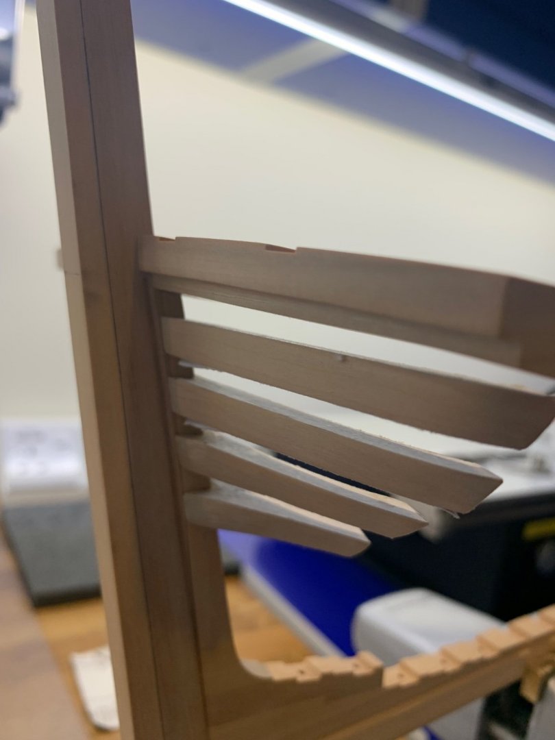
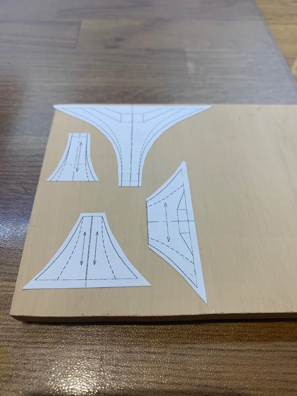
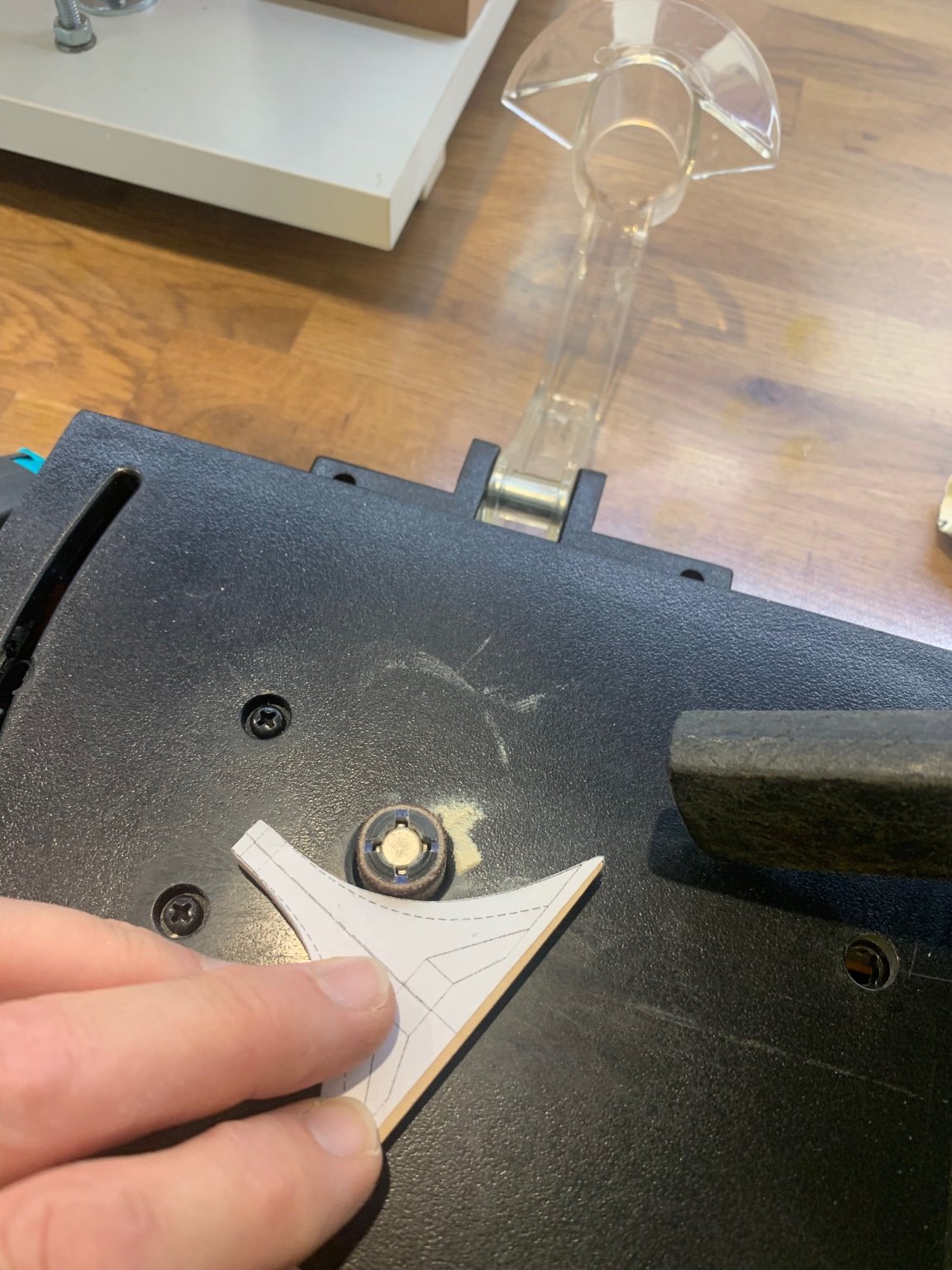
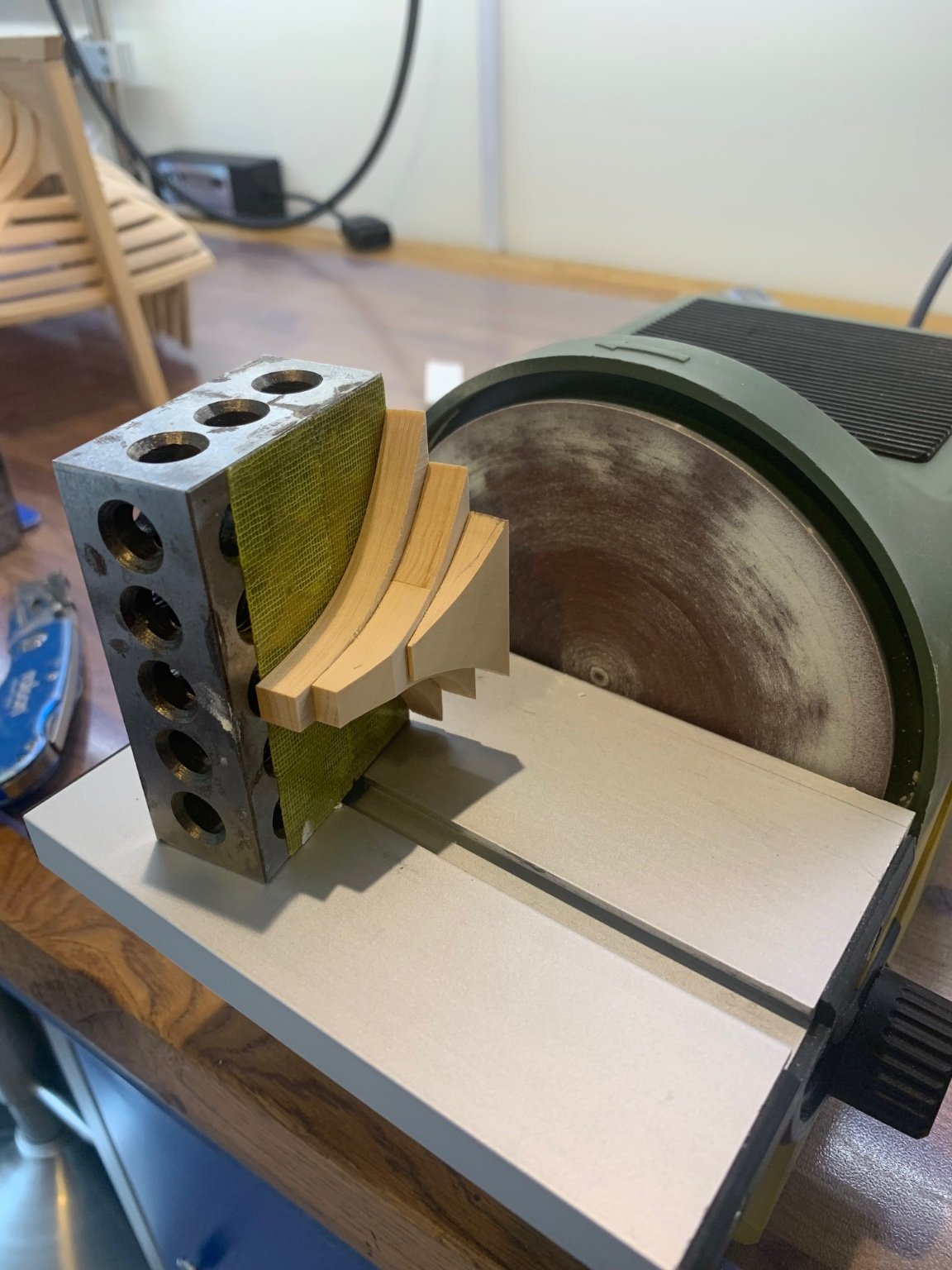
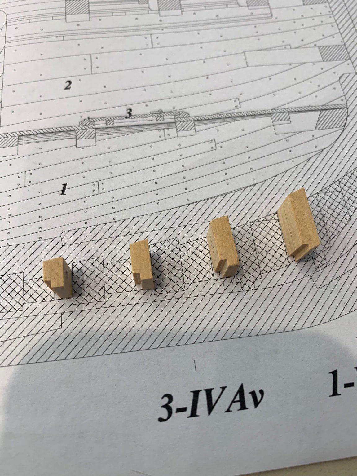
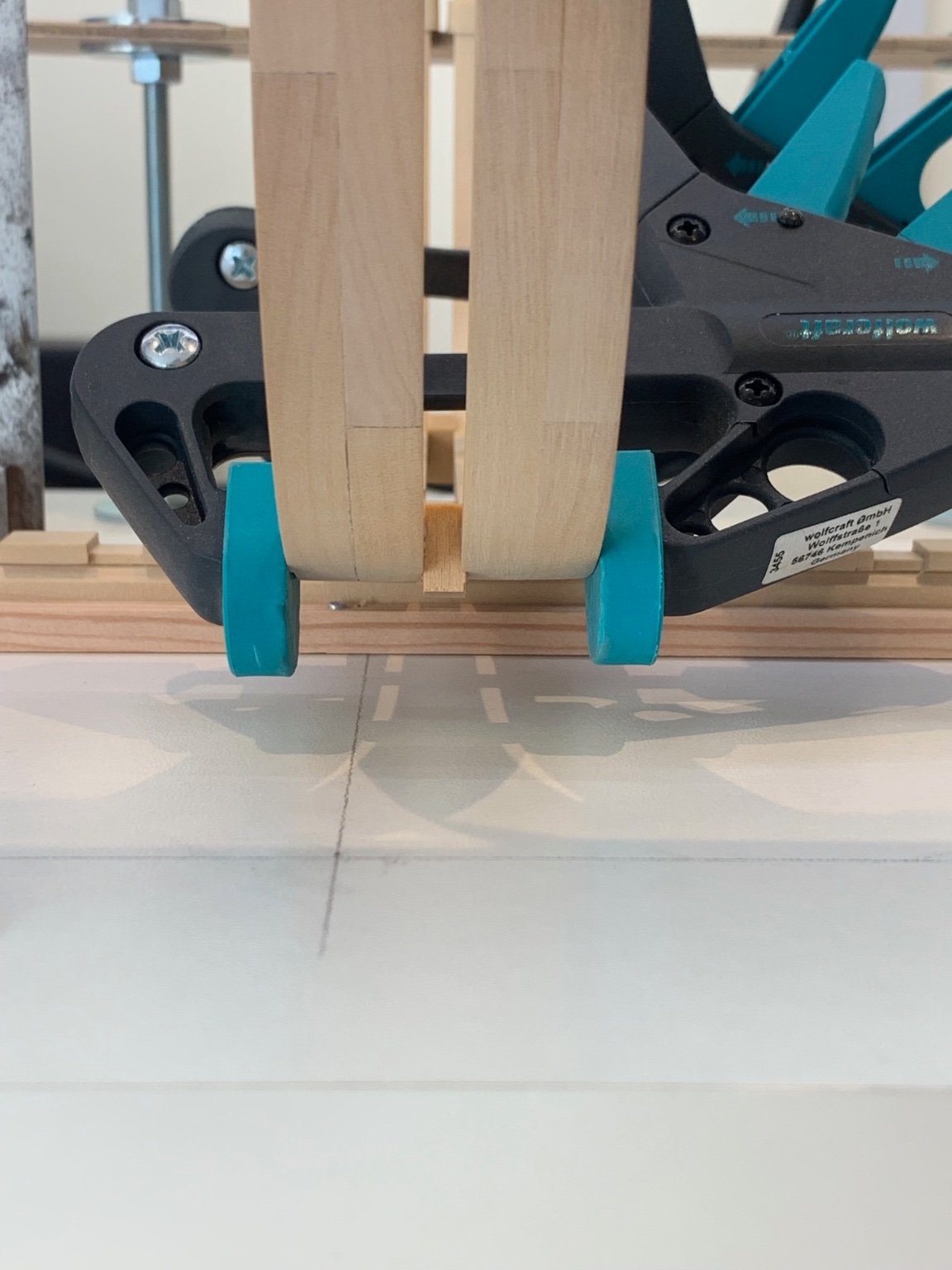
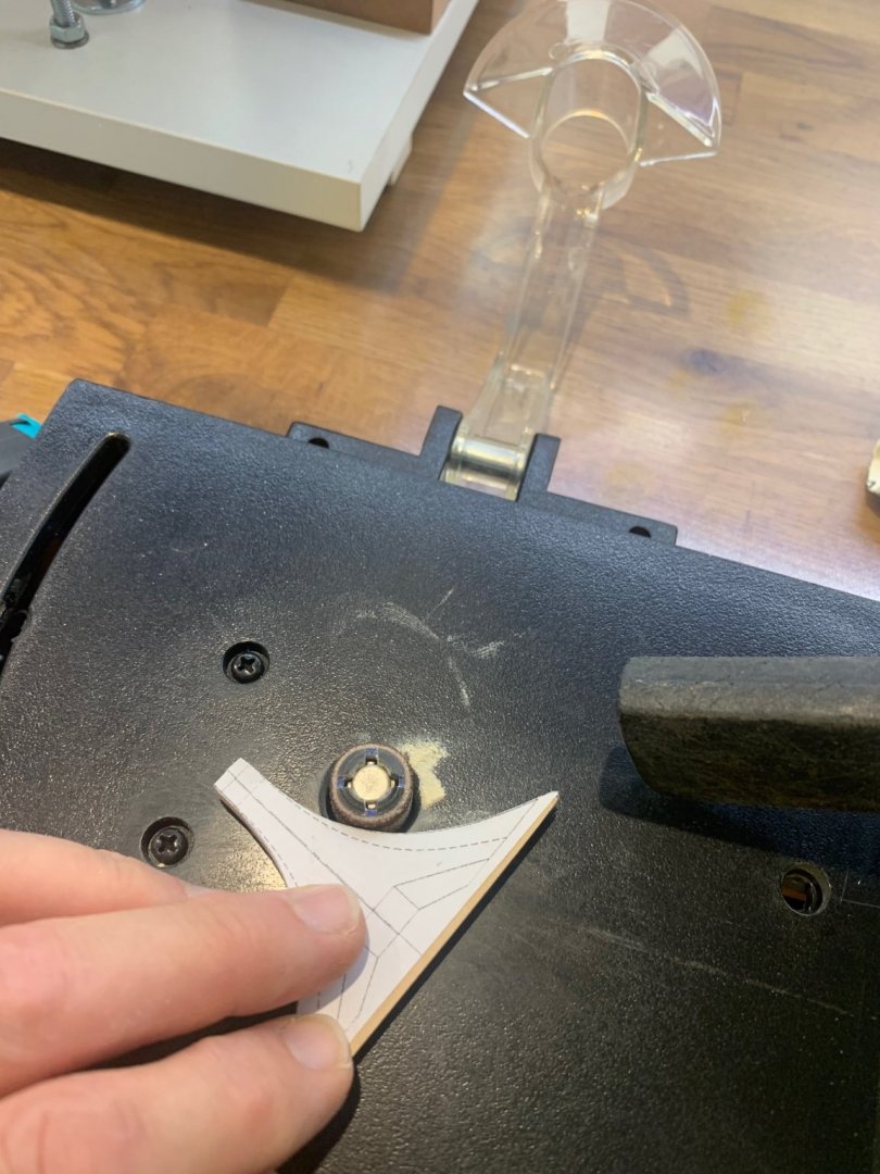
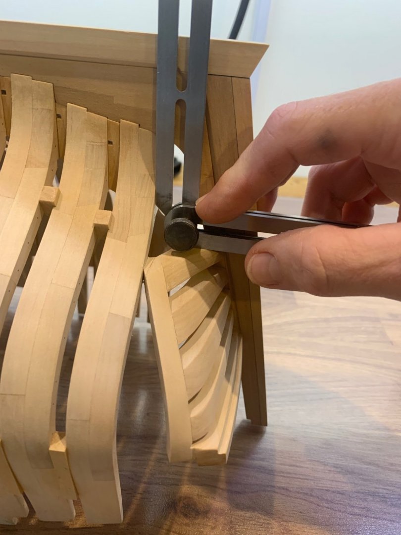
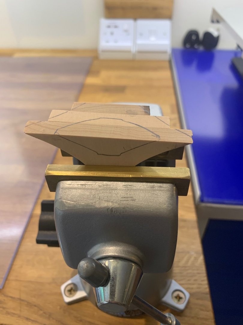
Hi All Things seem to have gone ok with the making of the solid piece that fits under the transom. I did the usual of cutting out templates making sure that the grain was correct before roughly shaping the parts and gluing them together. The angle between the transom and the last frame is slightly under 90 degrees; I don't know how everyone else takes the angles from either the ship or plans but I use a sliding bevel. I transferred this angle to a face sander and cut the top edge first but I forgot to take a photo of this step. I then I had to think about how to cut the taper at the rear keeping it square to the face. In the end I used double sided tape and fixed it to a metal block. This did the trick nicely and worked out the shape by taking measurements from the plan and scribing it as I went along. It's made now but I just need to rough shape it a bit first on the outside and also cut the recess on the inside. Cheers Mark


-
NAIAD 1797 by Bitao - 1:60
No Idea replied to Bitao's topic in - Build logs for subjects built 1751 - 1800
Wow your work is so inspiring - you are so precise its just lovely to see you progress. I'm watching this for tips and something to aim for in the future. Good luck moving forward. -
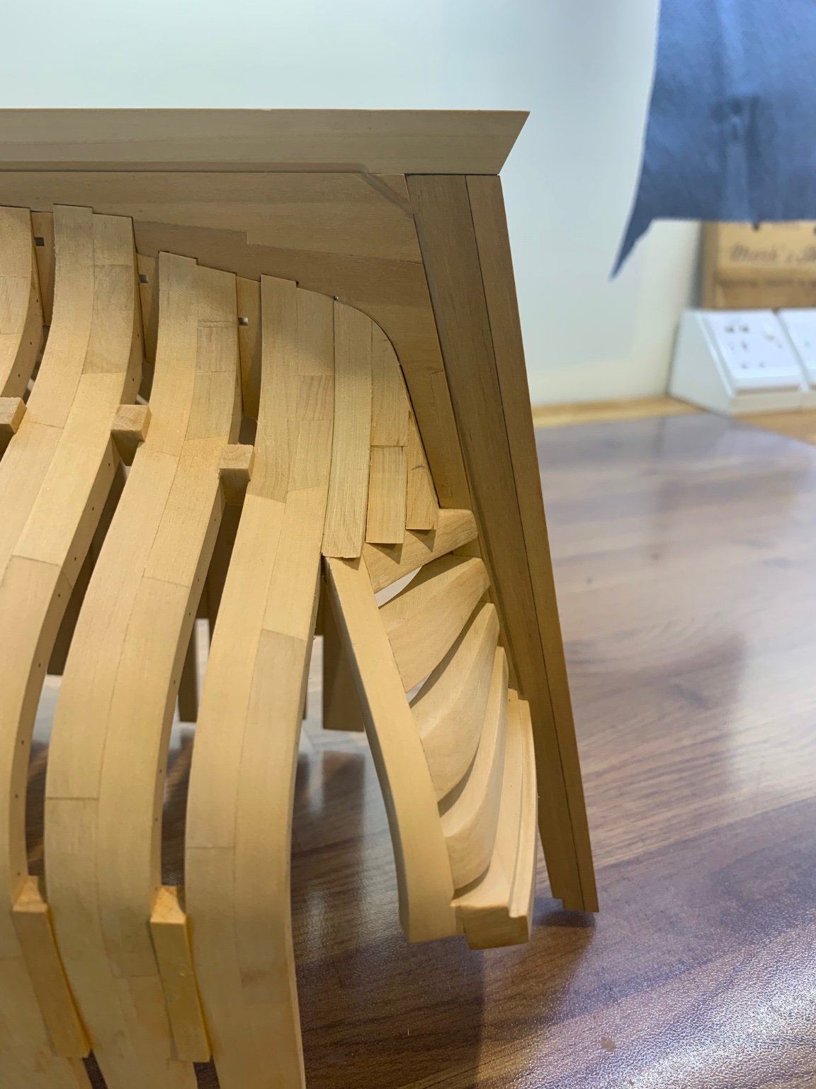
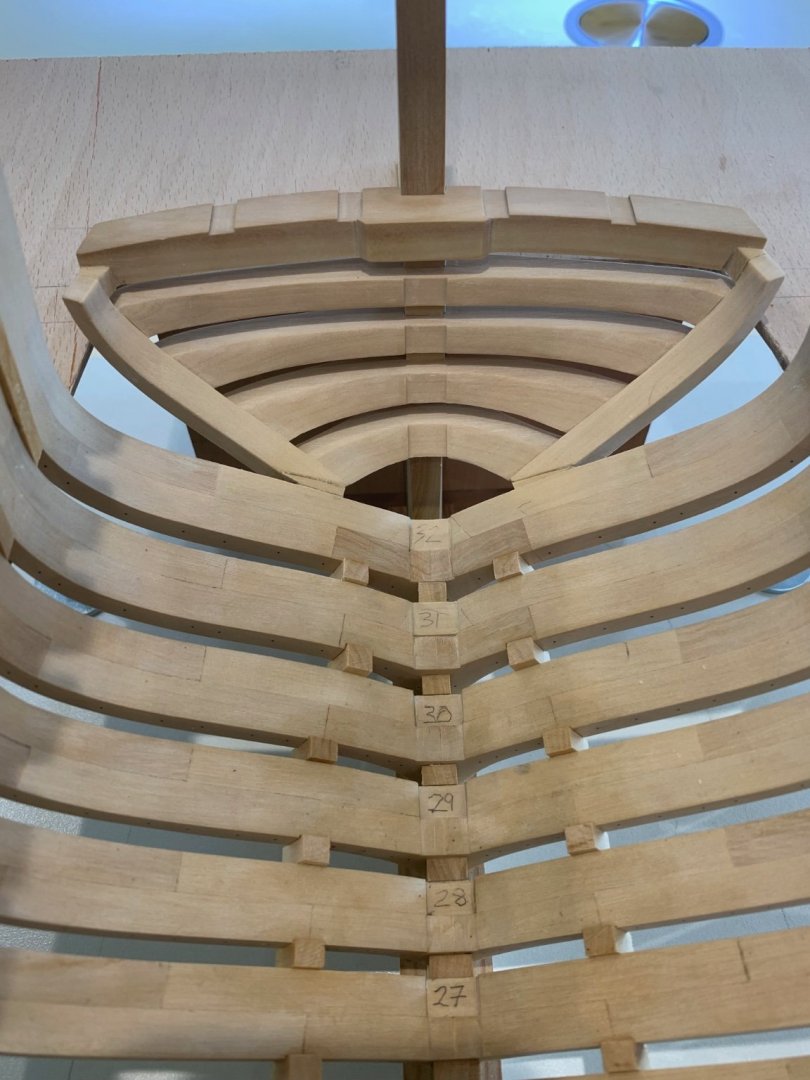
Hi druxey and Beef Wellington 🙂 Thanks both for the really nice comments and I'll try and post some more of how I work my problems out. I have created myself a real problem now; I should have filled the gap underneath the transom and behind the last frame before I installed frame 32. I was so focused on getting the frames in correctly this stage completely slipped my mind. So I now have the unenviable task of shaping this block to the correct shape and then sliding it into place. I'll give it a go and post my progress. Cheers Mark
-
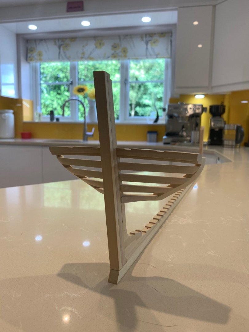
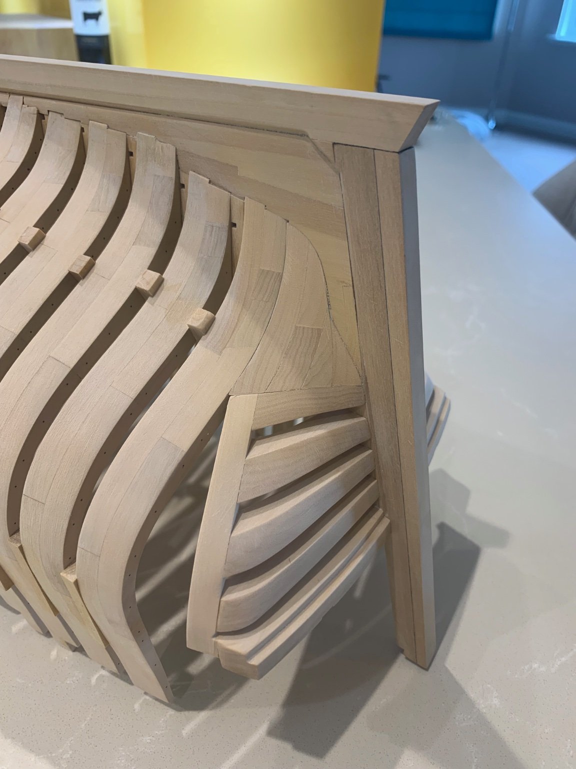
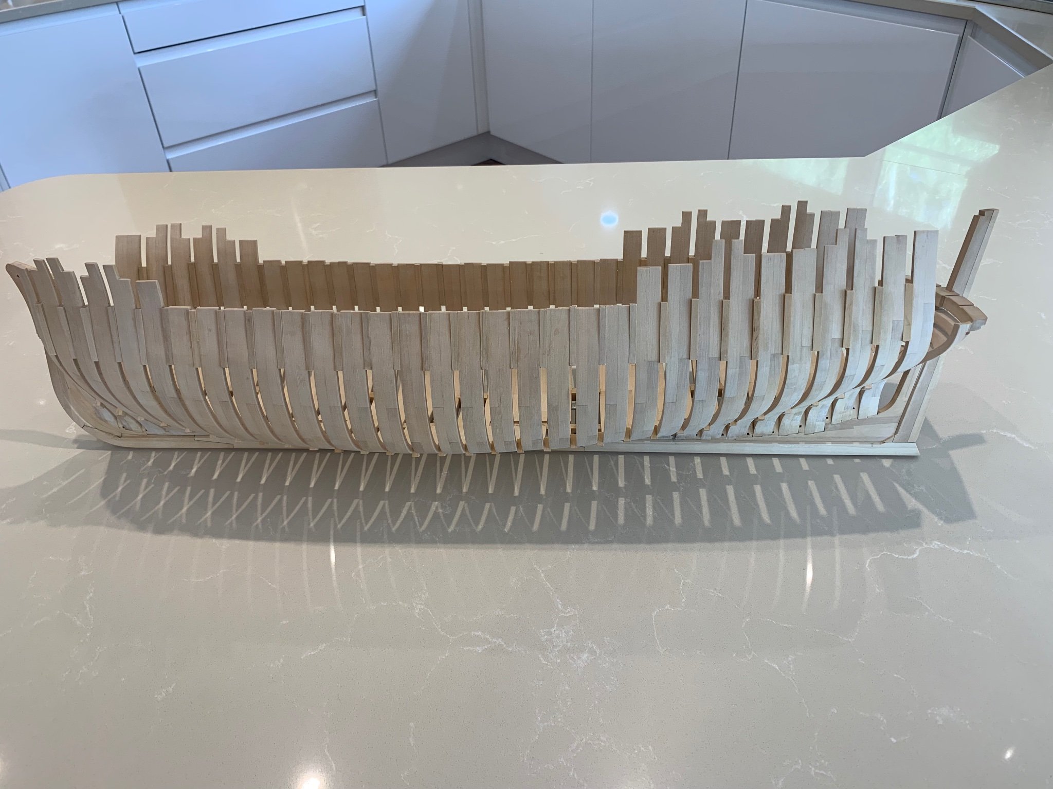
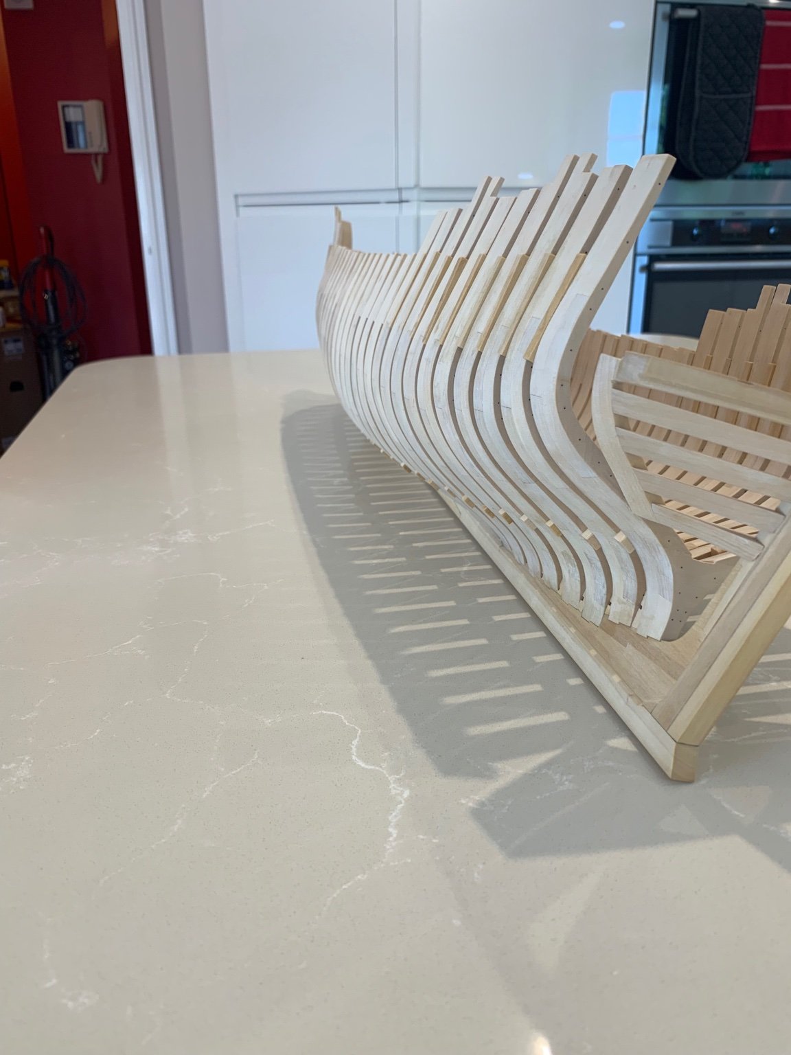
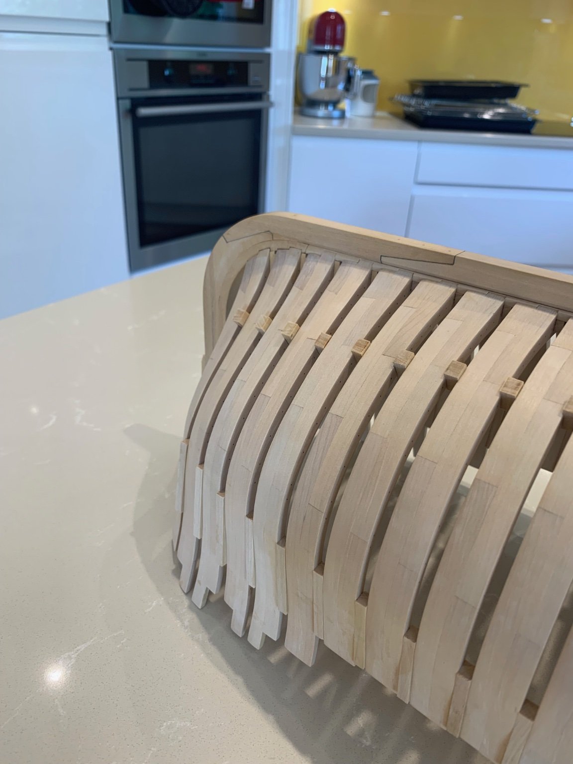
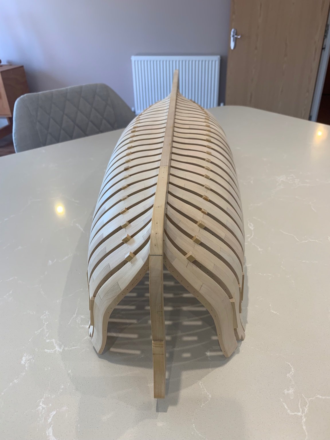
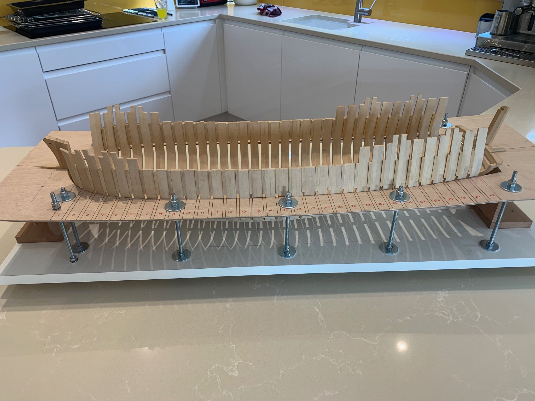
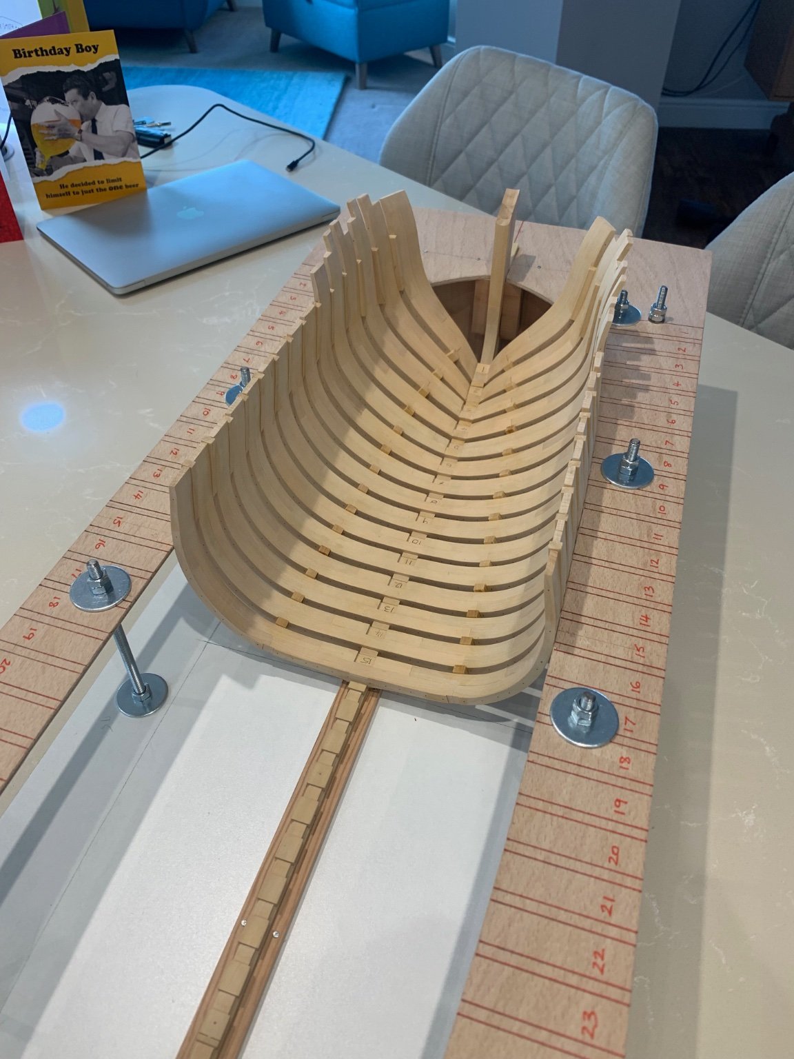
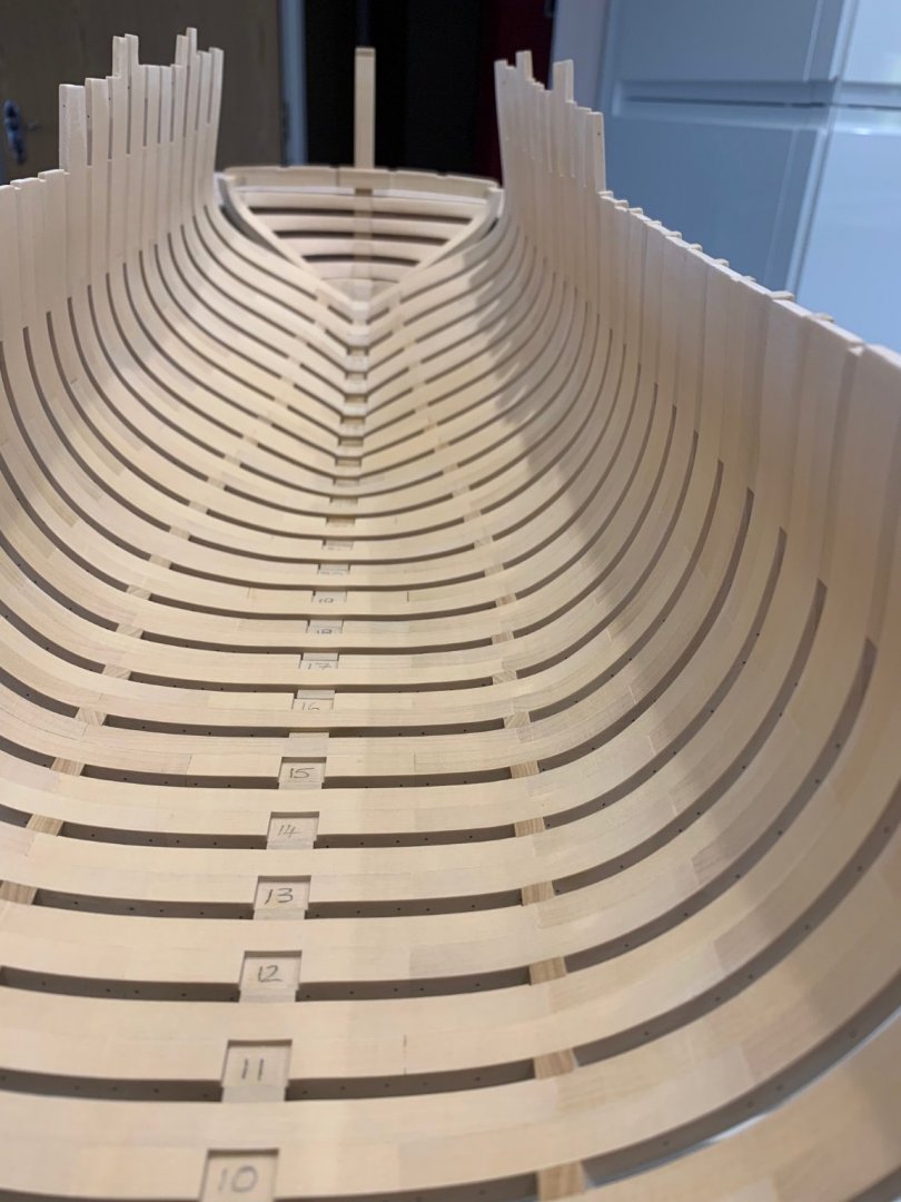
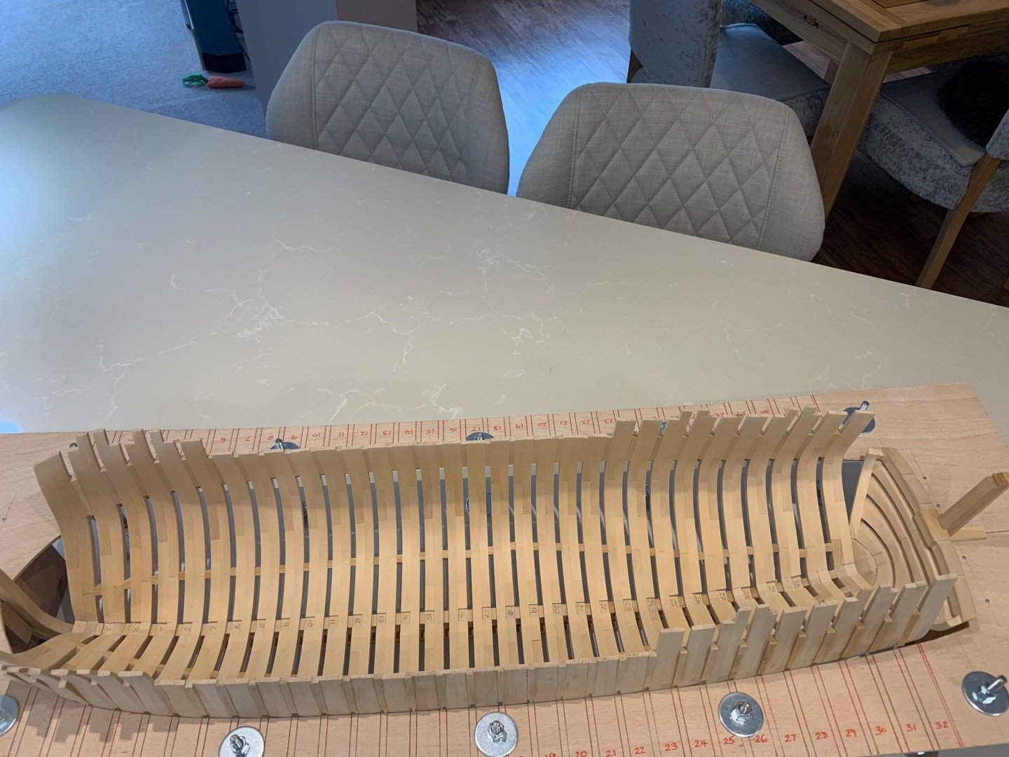
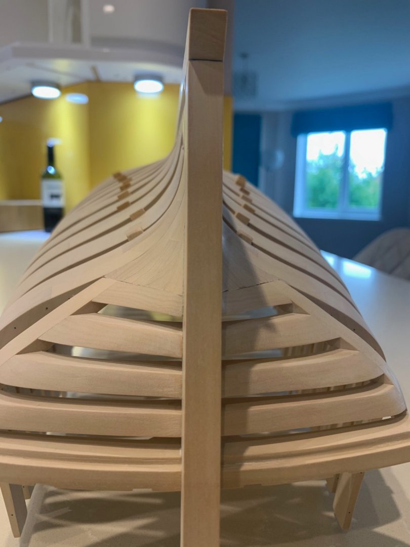
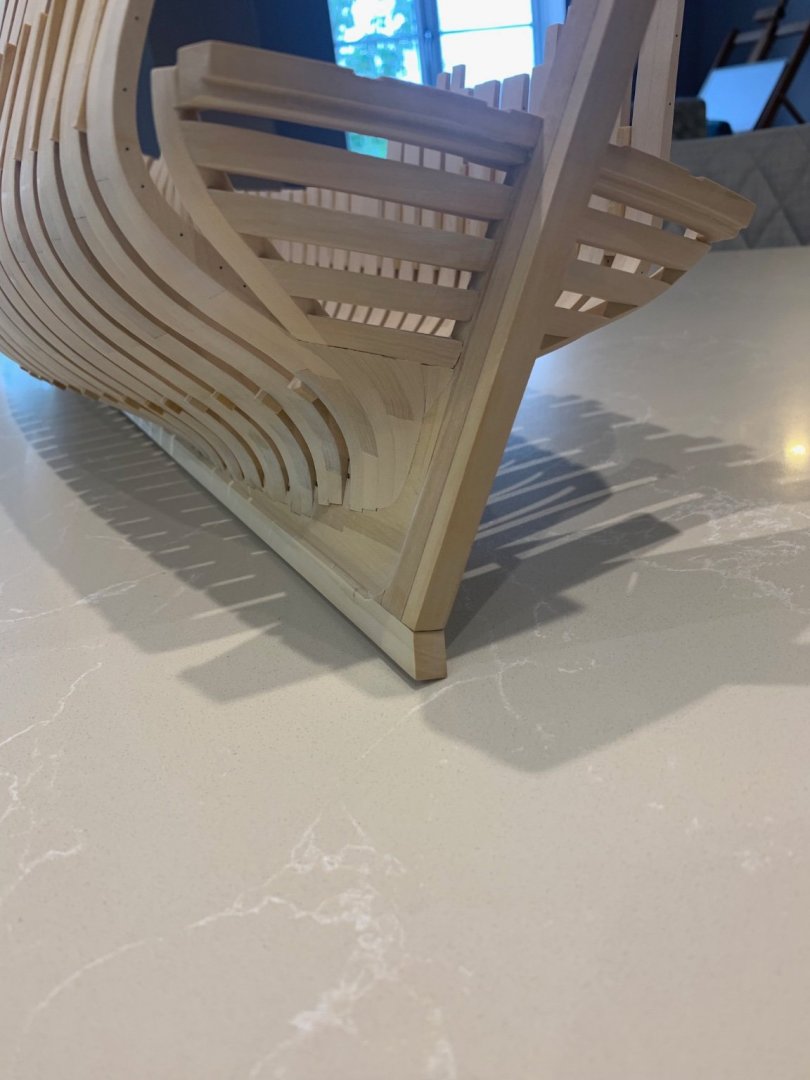
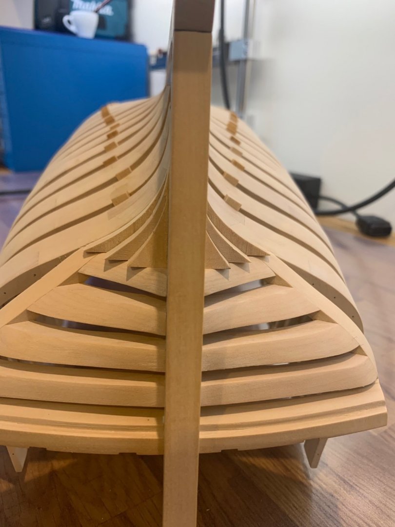
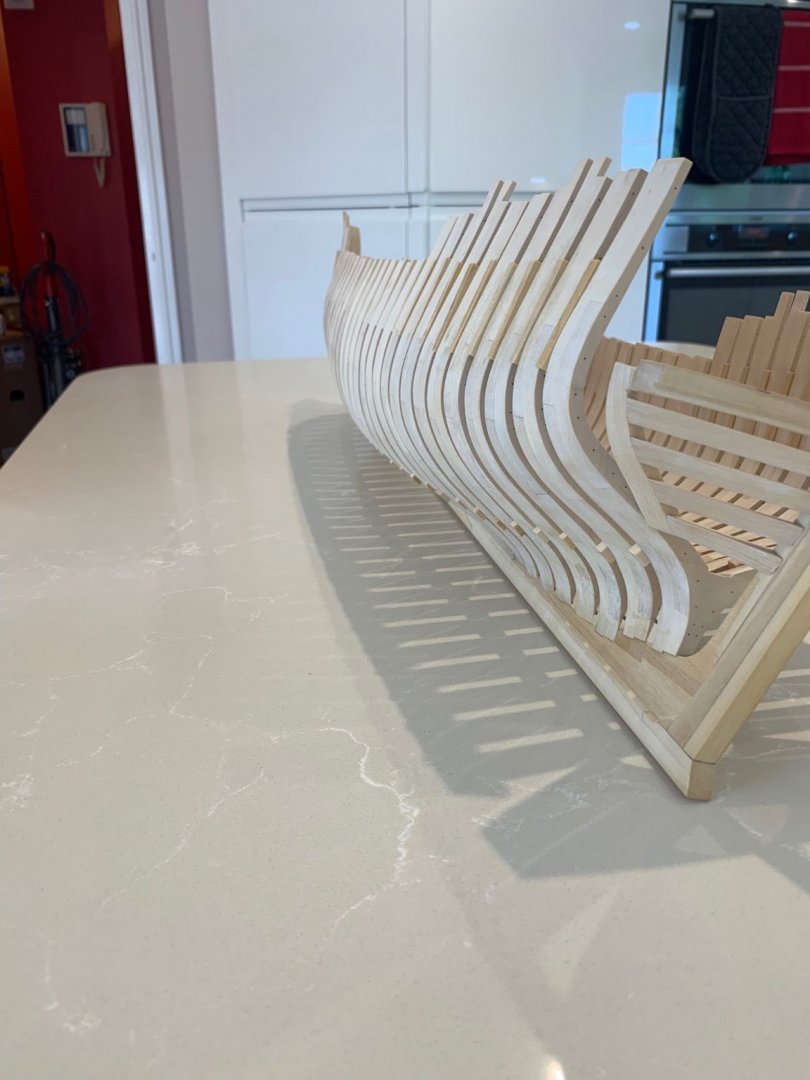
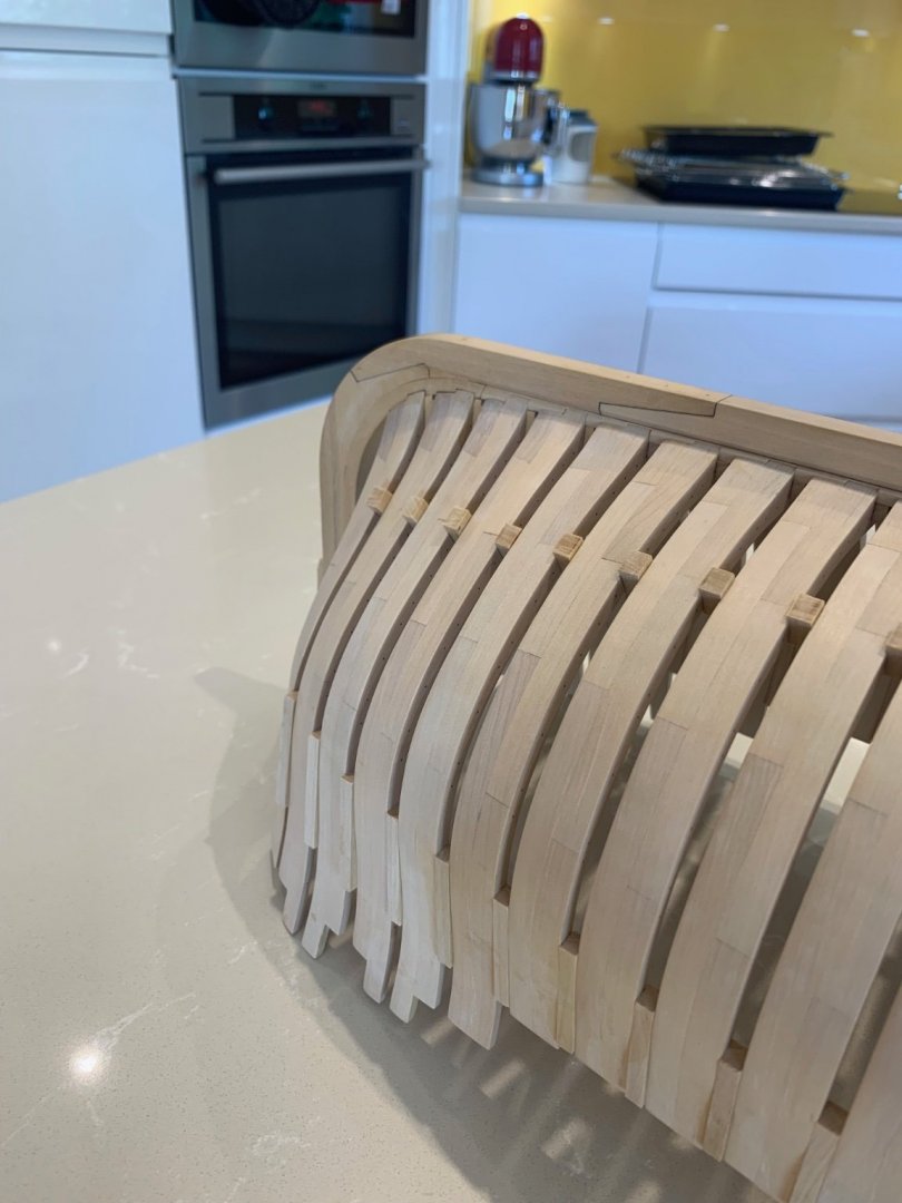
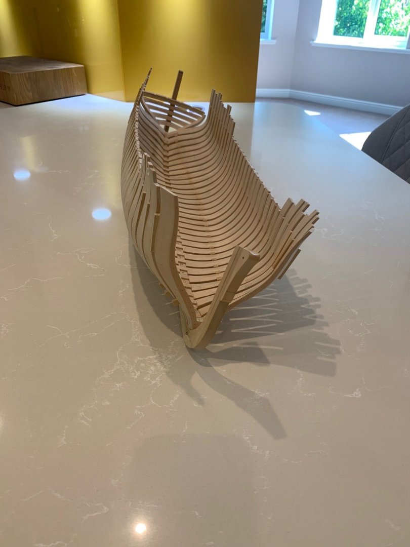
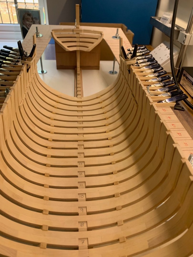
A few pictures of what is now starting to look like a ship.


-
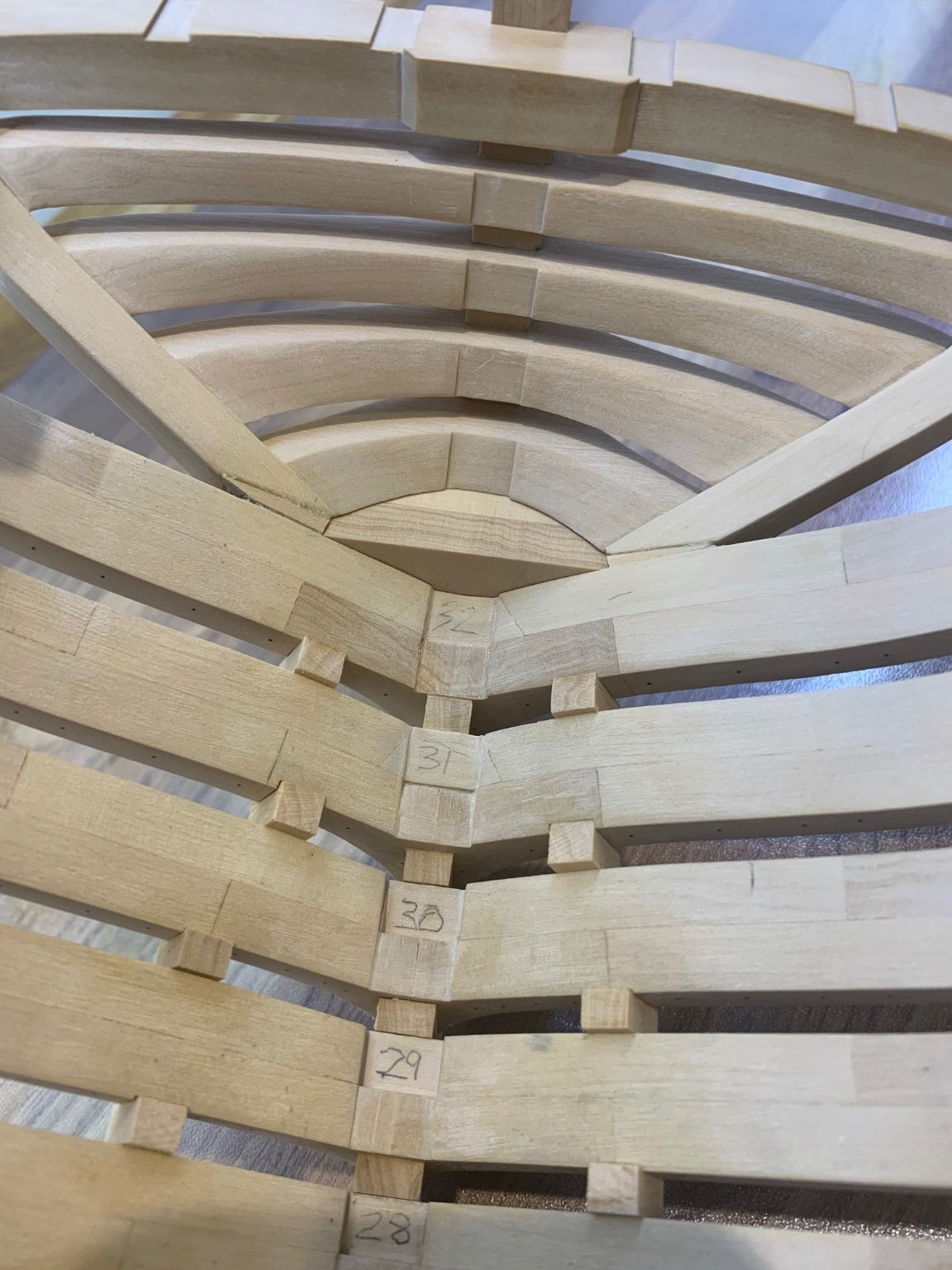
Hi Matt and thanks for the comment mate 👍 I've now finished raising the frames to the stern so thats all 32 frames installed. All was going well up to frame 28 but when I put the last 4 frames in I could see that they were leaning slightly over to the starboard side. Once again this was my fault as the aperture that I had cut on the assembly board was incorrect. So they all came out with some alcohol and I did what Greg suggested and started at the transom and worked my way forward. This produced a much better result. I'm glad to say that they all seem to be nicely vertical and square! I did have to make a couple of small wedges to fit between the last frame and the fashion pieces. There was a small gap due to my incorrect shaping of the mating faces. I can live with that though if I'm honest. Cheers Mark


-
Just read your whole build - fantastic job on this ship it looks really nice and clean 👍 I'm looking forward to your updates - BTW - best forum name ever 🤣
- 47 replies
-
- 2
-

-
- Modellers Shipyard
- Perseverance
- (and 1 more)
-
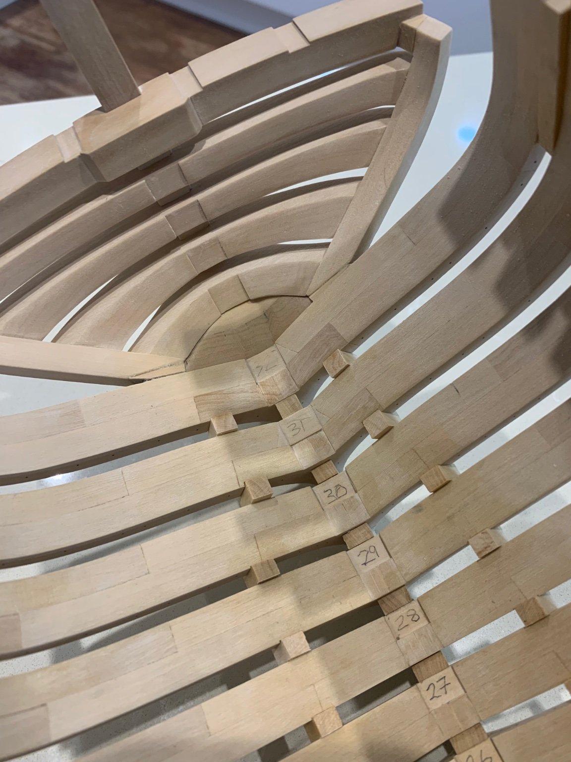
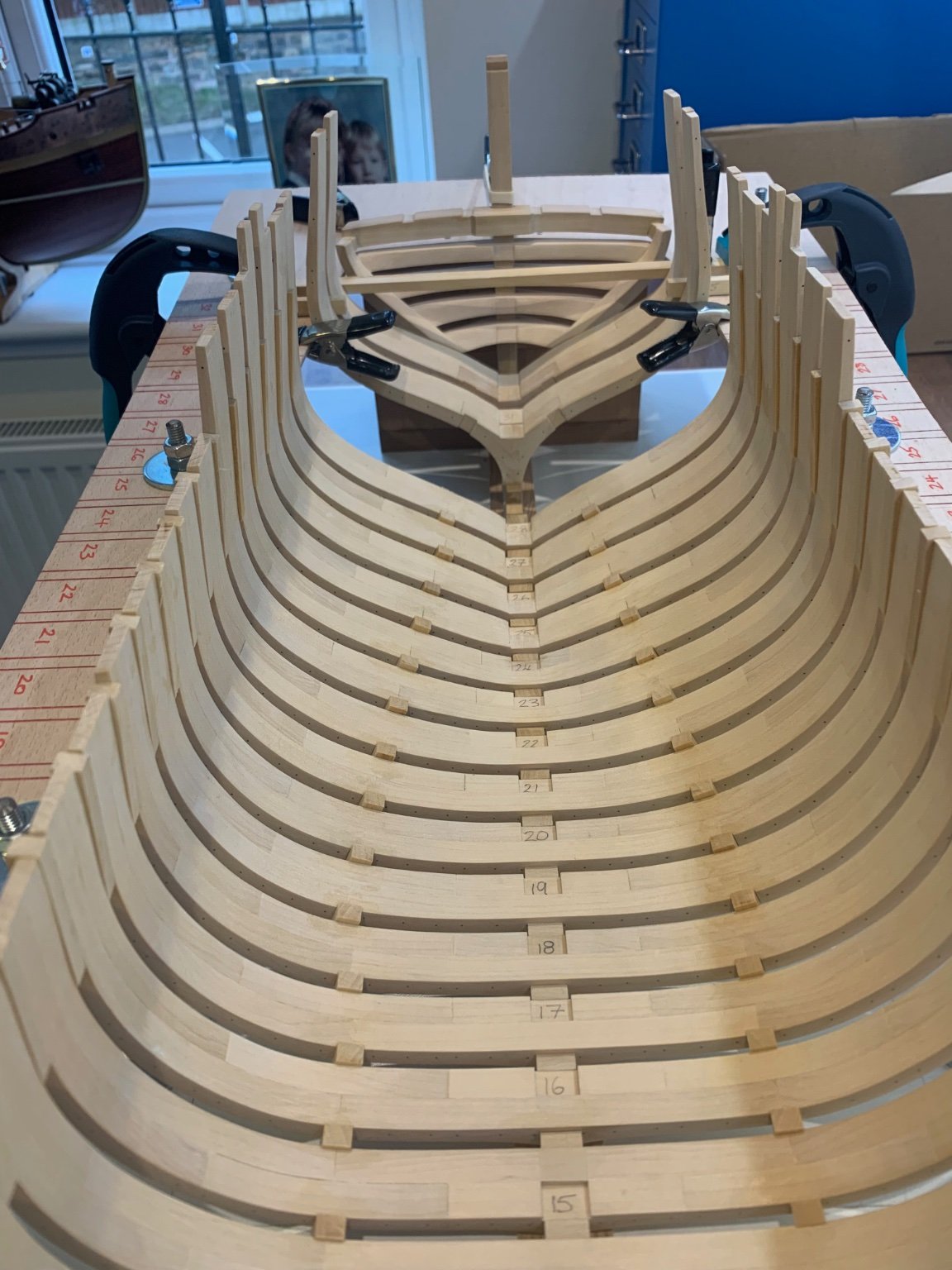
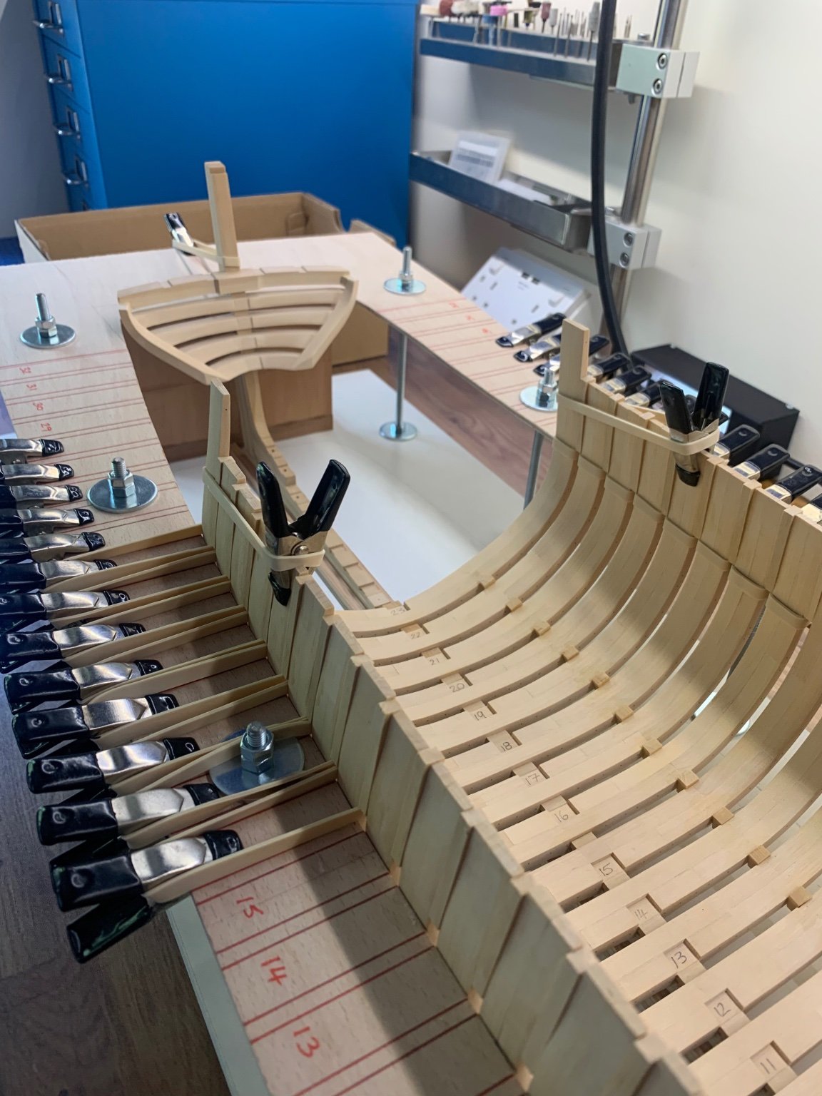
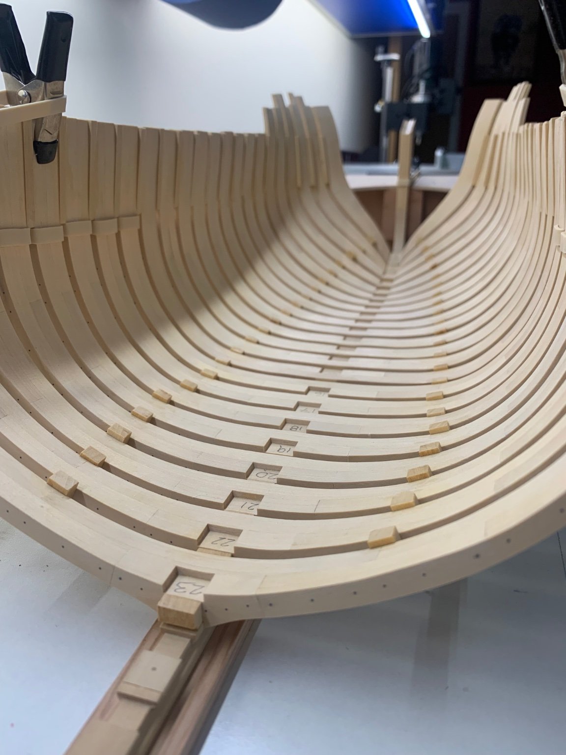
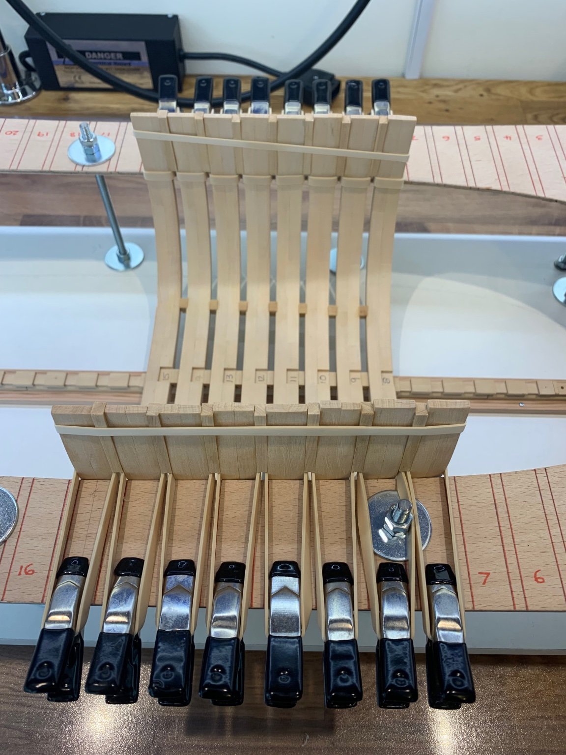
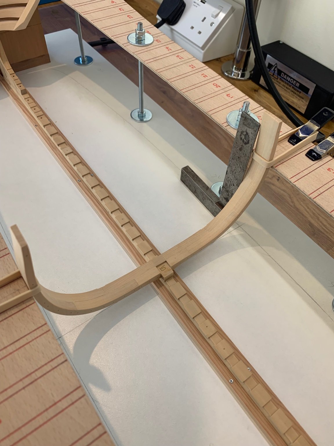
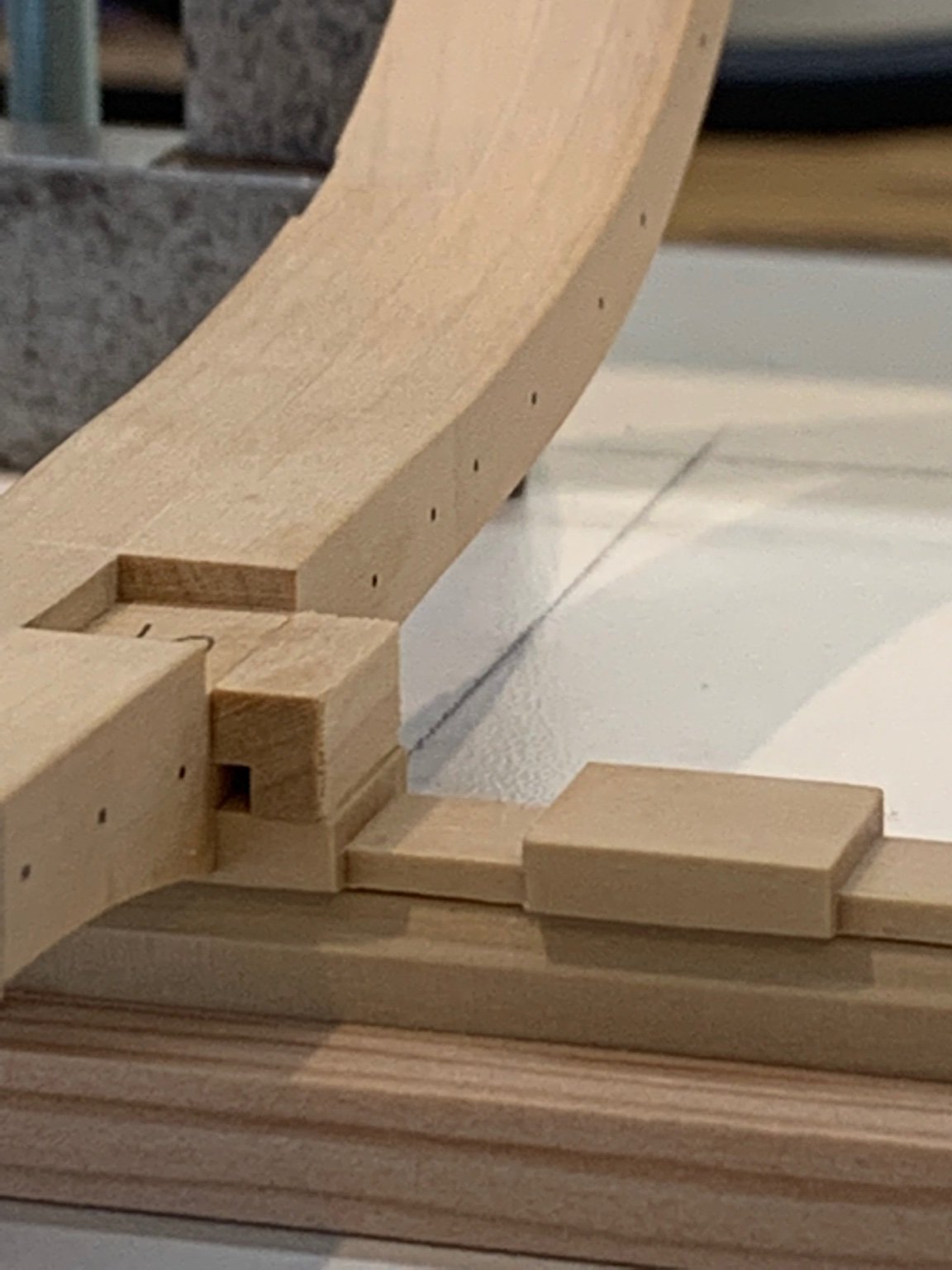
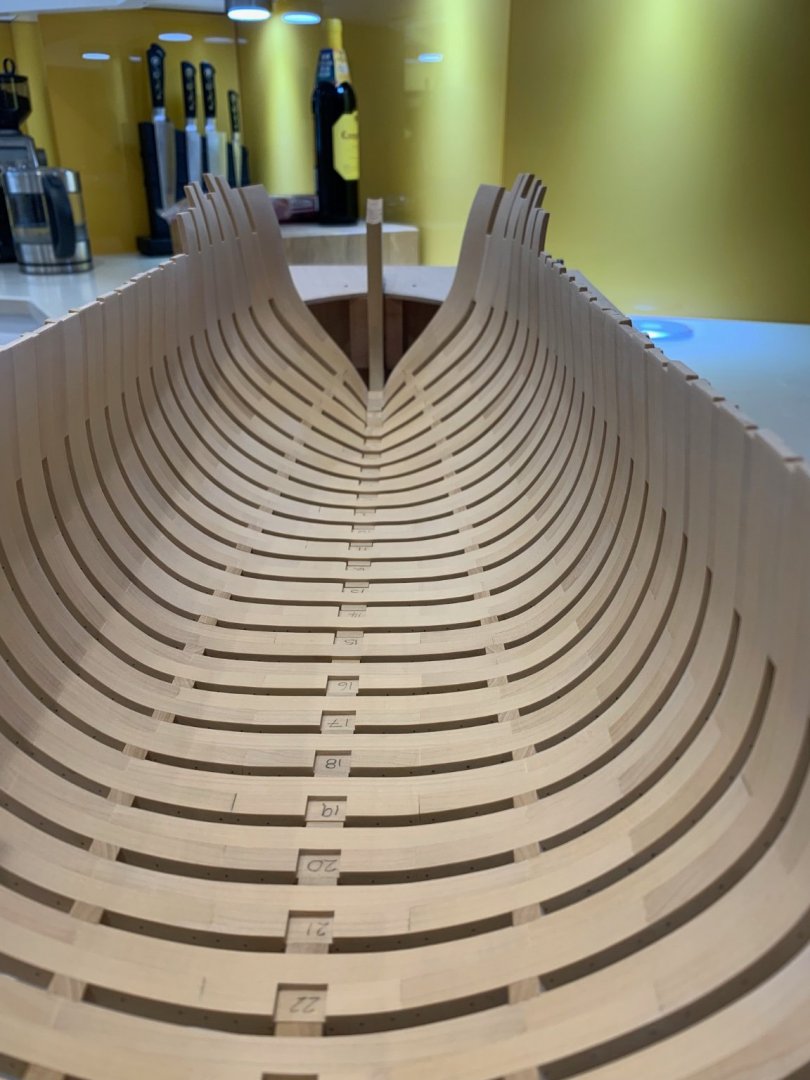
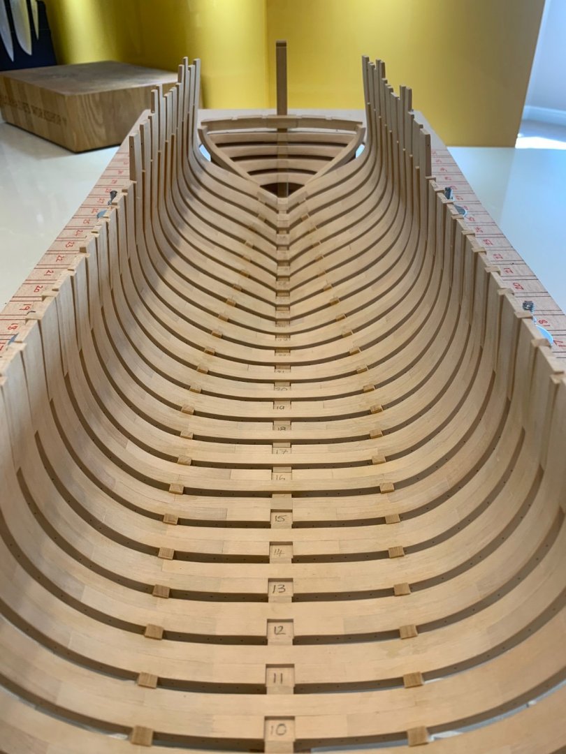
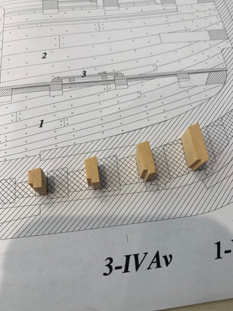
I actually managed to get some more frames in today which wasn't planned but you've got to take the time when its available! I've now raised frames 16 - 23 and they seem to have gone in nice and straight. There were no real issues it was just a case of repeating what I have already done. The floor chocks with the limber channel start to rise at frame 20 so there are a lot of bespoke pieces to be made. The rise starts off very slight and becomes much more pronounced as you move towards the stern. These chocks also rotate their limber channel 180 degree's at frame 23. I missed this until it was too late so mine will have to rotate at frame 25. Some you win and some you loose I guess. Cheers Mark


-
Just added my new membership number too
-
Hi Marc thanks for the really nice comment mate and I have to say I'm very surprised by the overall reaction to this build. I just try my best and thats pretty much all I can say. Please remember that I have pretty much built this ship twice over so far with the amount of things that I have made incorrectly. I think that the choice of ship for anyone's first POF build is critical - I chose Le Rochefort after much research and also have messaged people like Mark Taylor for advice. It would be so easy to try and build something bristling with cannon but that would have been far too much for me. I have in my building arsenal a fantastic book by Adrian Sorolla which is basically a step by step building guide. I also have Gerard Delacroix on this forum who made the fantastic monograph that I work from - oh and the many fantastic builders on this forum who give me the best advice. It's not one of those things that you do on your own and making mistakes is just part of the process it would seem. Typing this out has made me think that I really ought to join the NRG if only to put a few coins in their coffers.
-
Hi Nils and thanks very much mate 👍 I can't get much more done now until the weekend. I'll start installing the frames towards the stern next and fingers crossed they fit as well.
-
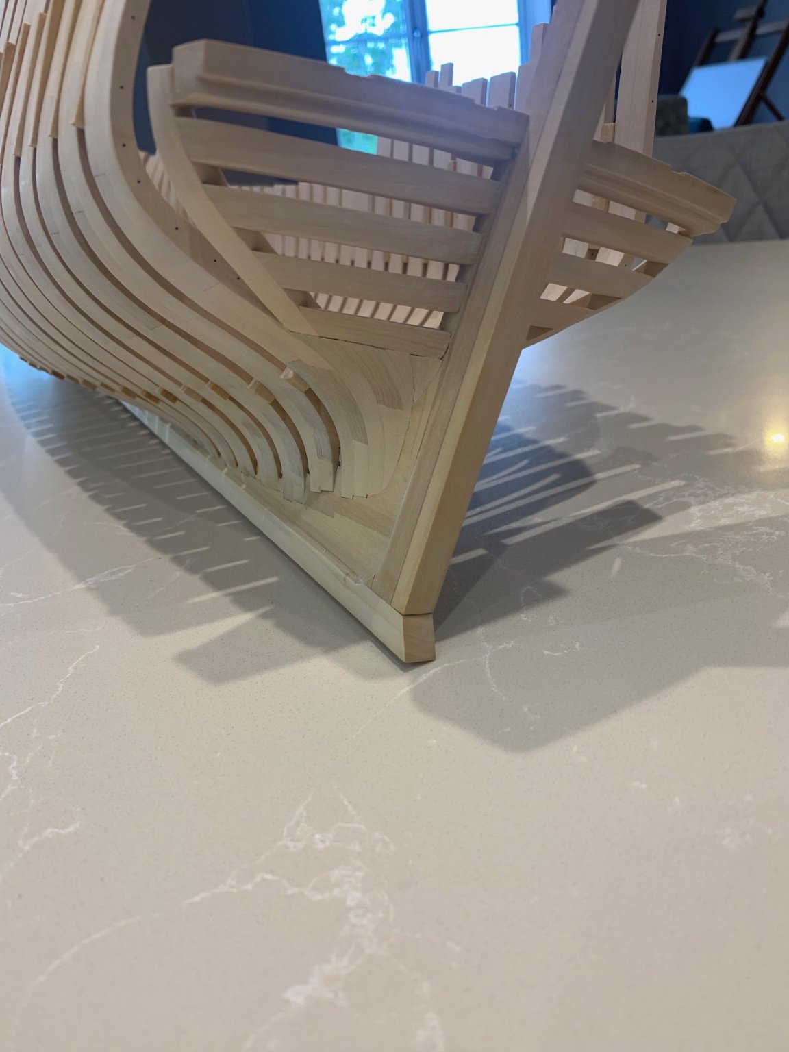
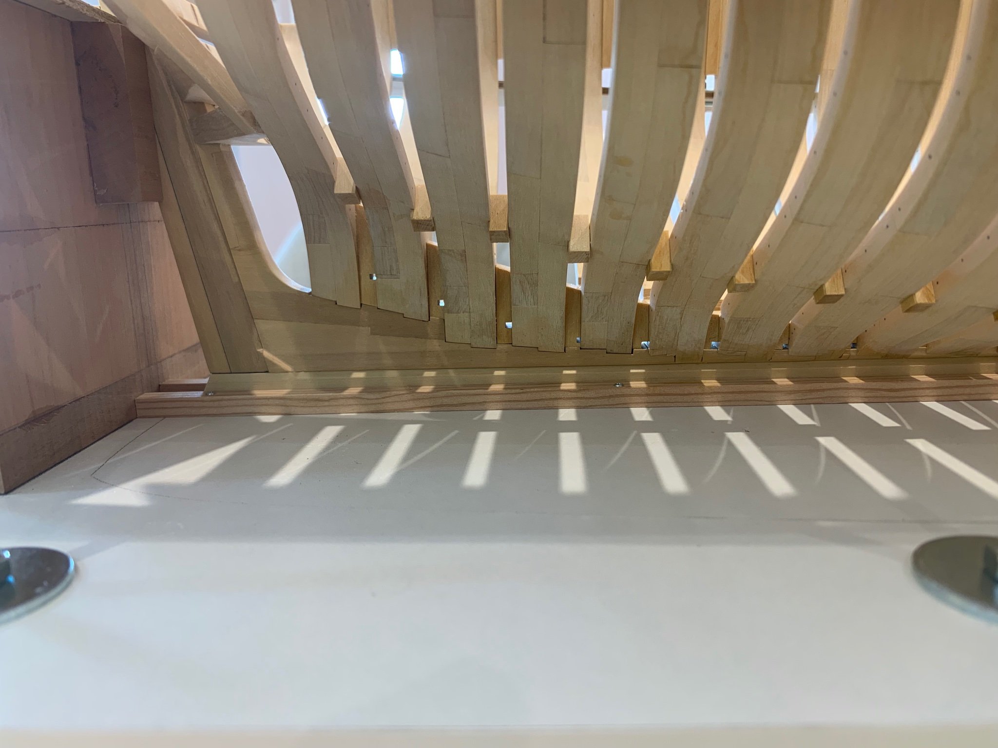
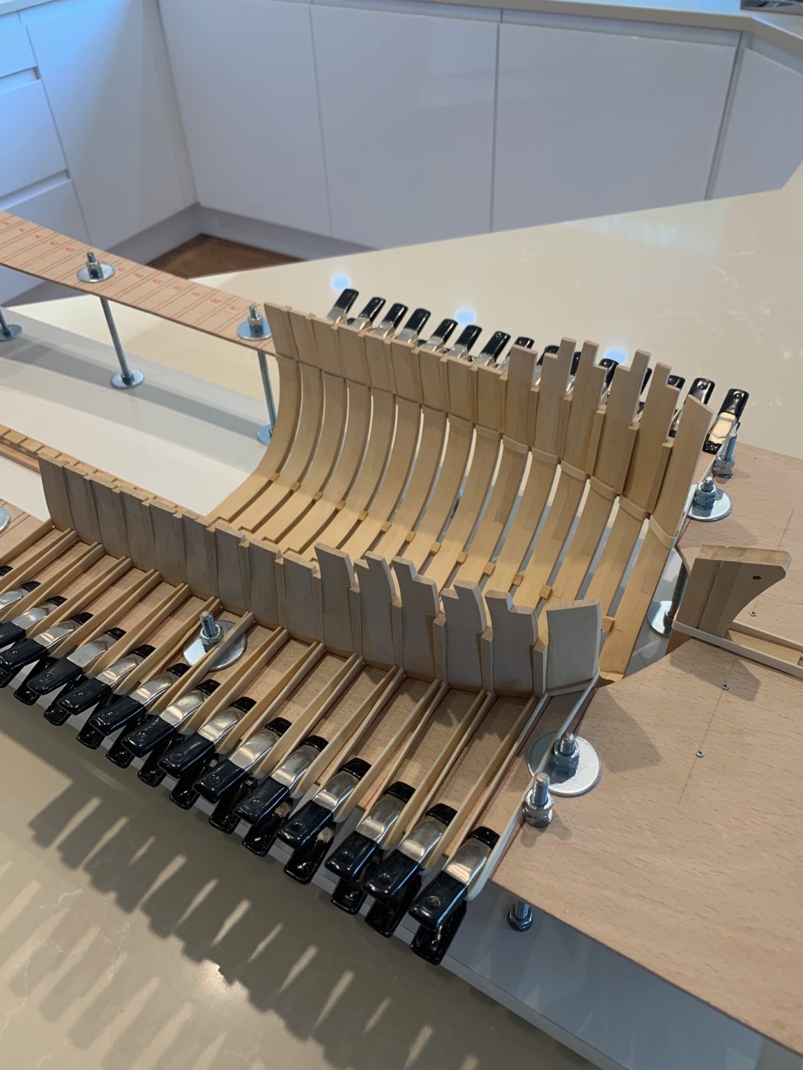
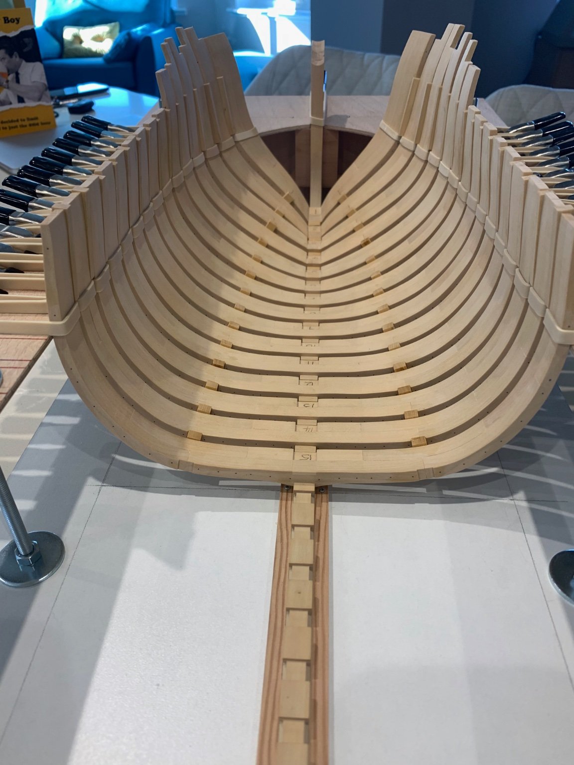
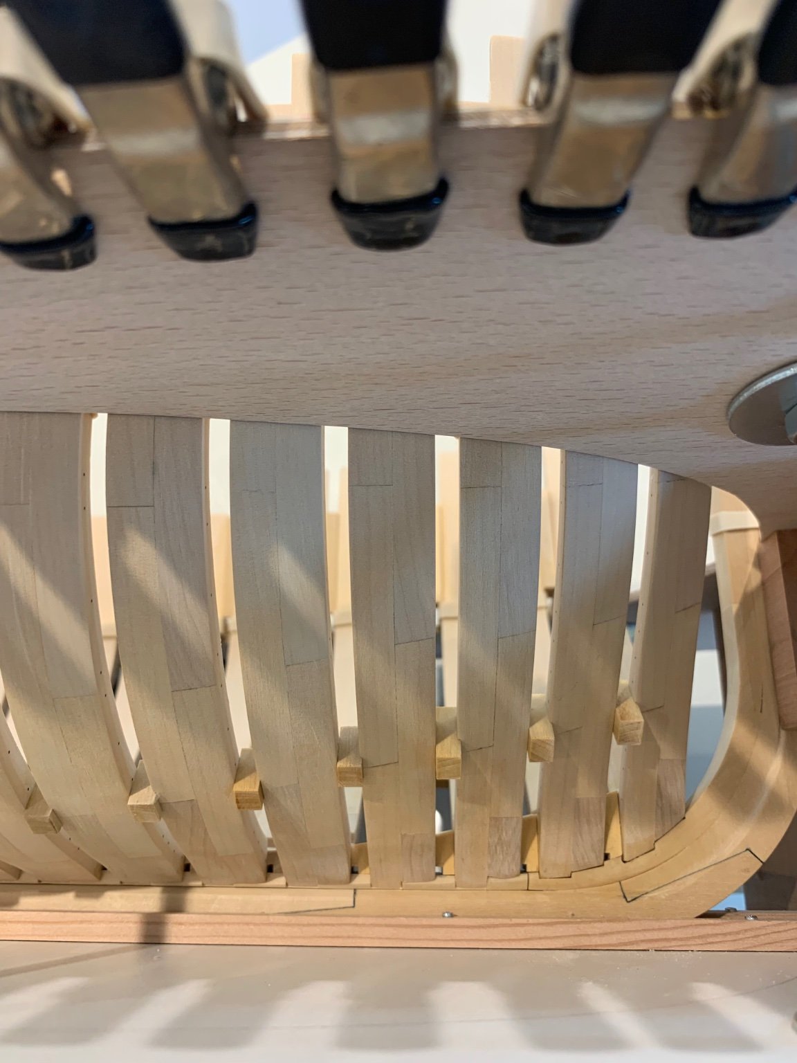
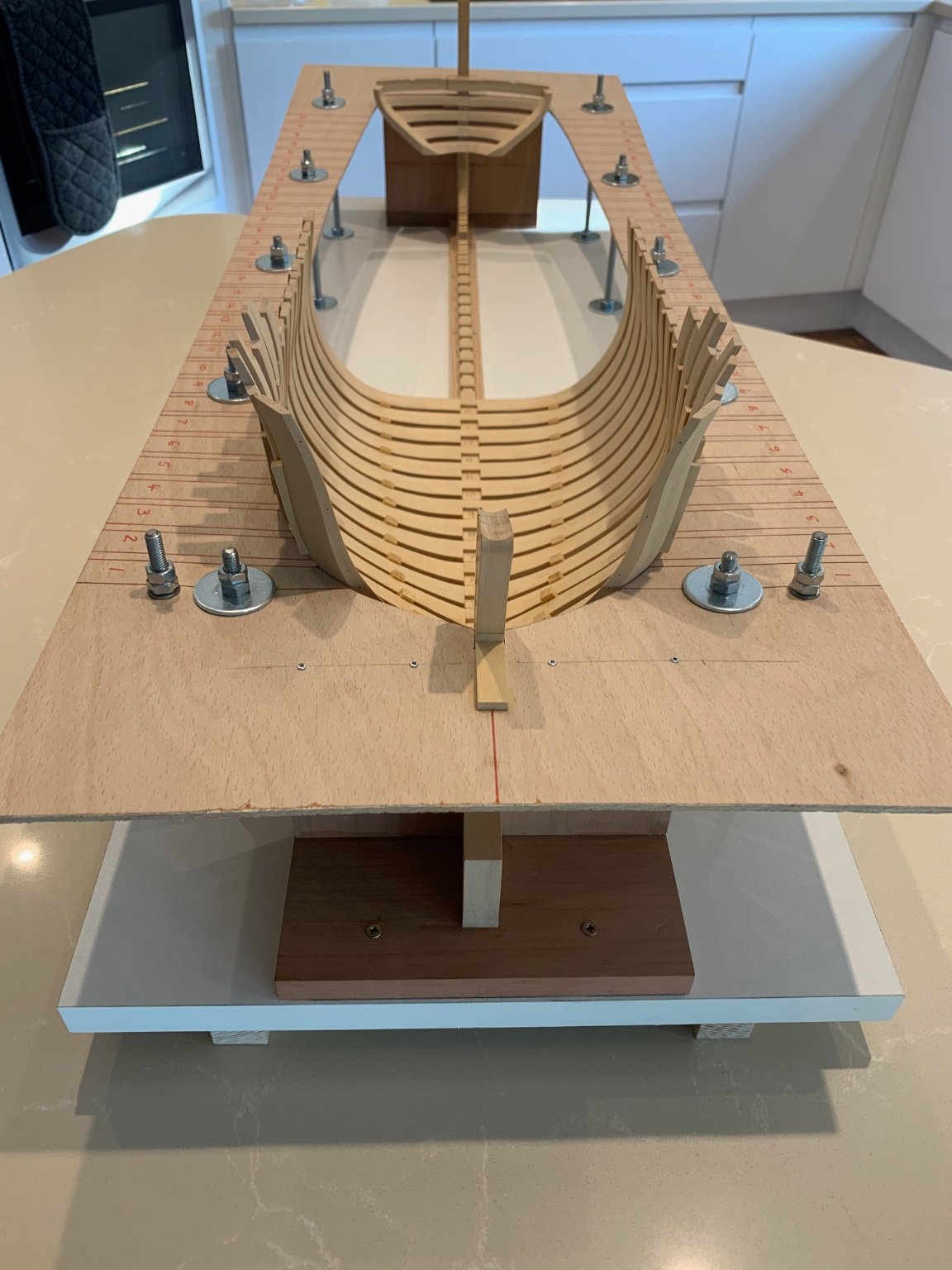
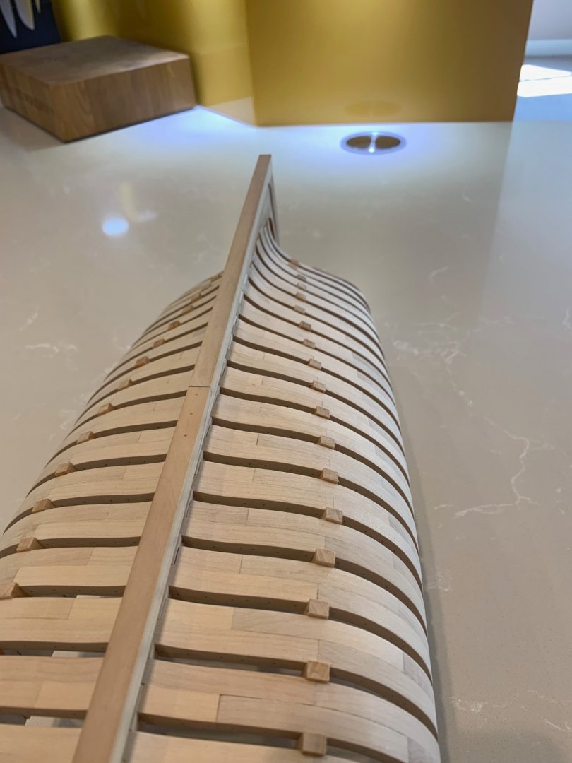
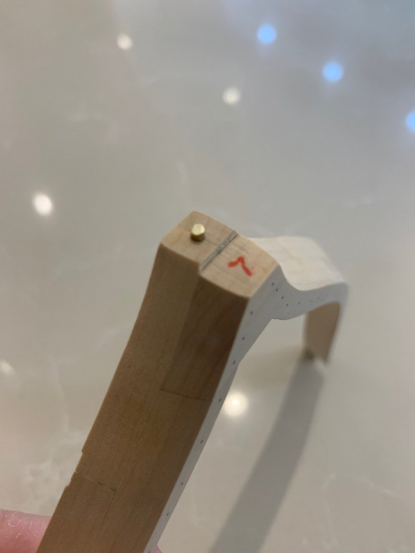
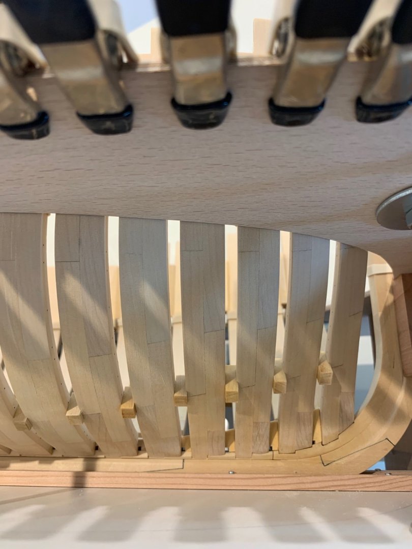
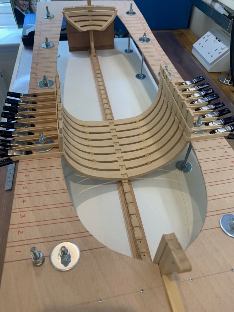
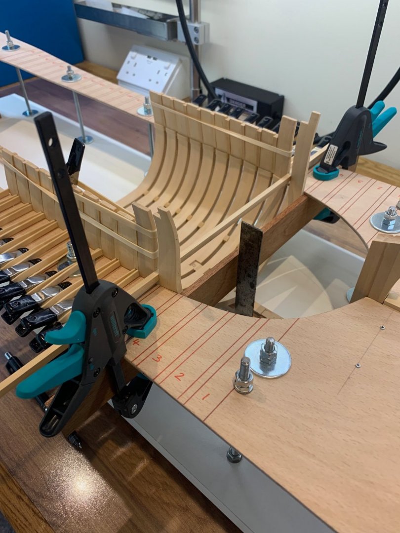
Hi All Thanks for the likes 😀 I've got some more work done in between decorating. I made the rising chocks as per the plan and have now installed the final four forward frames. I like the way if you look through the frames underneath the way the chocks rise up to meet the stemson. One is slightly high but its nothing a quick shave with a chisel won't sort out. Frames 1 and 2 have a small 2mm dowel to hold them in place - I didn't have any wood of this diameter so I used a small piece of brass instead. It all seems to have gone together ok. Here's a few pictures - with and without the holding bands Mark


-
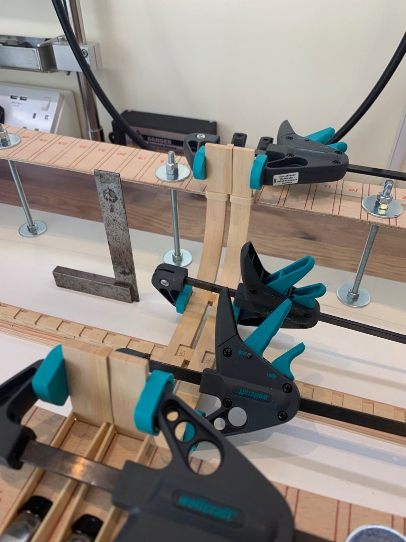
Greg and bitao thanks for the words of advice it really does help me learn. If I was starting over again I would have certainly left far more on the frames than I did. That's one for my next build 👍 I've got some more frames raised today and it seems to have gone to plan. I have found though that my frames are not quite matching the guidelines that I made on the building board. I have been checking the frames for square to the base board and they definitely are. I trust my engineers square far more than I do my marking out. Its a bit basic they way that I check for square - just a flat piece of timber clamped to the face of the frame; it seems to work. The next forward frames require me to make bespoke chocks off of the rising wood. As the frames rise up the apron the chocks follow. I don't think this will be too hard to achieve. Here's hoping

-
Thanks Greg - I love this forum as it gives me the inspiration to try harder. I have to be honest - I just don't know any better which maybe in my favour. I have been so aware of cumulative error since raising the frames and I think that I have been correcting this starting the process. I try and rely on the plans - wow this is still my first POF build and I'm learning so much. However - what a great challenge eh!!!!!!
-
Hi Mark and thank you - so far I have found that its my milling that is causing me issues. The top timbers have not been cut to their final height and the chocks between them seem to fit very nicely at 4.5mm. Its keeping the frames nice and perpendicular which is a positive sign. The small lower chocks are slowing me down simply because their width varies due to the rebates that I milled. I have had to make some very very fine shims to make sure that everything fits together tightly - I'm talking about 0.01mm shims but I think its worth the effort. If I had used my Sherline mill that I have now I think that my efforts would have been reduced as I used a Proxxon mill to cut the rebates that I am talking about. There is no comparison between these machines and I would also say that my abilities have reflected this too. We all get better as we move along. Thanks again - Mark
-
Thanks Hubac's Historian for the kind comment. I just use my iPhone as I don't actually own a camera. Hopefully the rest of the frames will locate where they should but based on my experience so far I think I may have a few issues ahead to overcome.
-
Hi Everyone I've at last made a start on installing the frames. I had to make a lot of adjustments to my building frame as I realised that I had adjusted it to follow the line of the whale rather than the line I required. I just misread the drawing but thats all sorted now. I've made up lots of chock blocks for between the frames so hopefully it will all go ok. A few pictures below of the first two frames complete with keelson chock with the limber channel and the upper and lower chocks too. I'm sure that I will need to make some alterations along the way but so far so good. Mark


-
I actually have no idea - thats not a pun - but I have never used an x acto blade. I use surgical blades and I can use up 10 a day as they blunt very quickly. However they are also very cheap so as many as I throw away I always have a sharp blade at a very low price. I also like the different shape of blade that I can get with surgical blades and I know that I can swap them out at any time and not worry about the cost.
-
Hi all - sorry for the lack of updates but I started some decorating at home which has turned into a full blown building job so I'm fitting the ship building in-between. So what have I been doing - well finding more patience than I thought that I would ever have. I discovered that just because I had made the parts for the transom did not mean that they would all fit perfectly together. Wow what a challenge this turned into for me! To get all of the parts to line up so that all of the joints were nice a square and that the shape of the transom was also correct was far more difficult that I thought it would be. I managed to pretty much ruin the first set of lower transom parts that I made in my efforts to get the fashion pieces to fit correctly. It then took a week of soaking in IPA to get them unstuck as the joints were tight without the glue. So here is what I learnt - leave the templates on all of the parts after gluing them together so that you have a reference to what you are trying to sand too. Without them I was just sanding blind which just made things worse. Also leave enough on the parts for the fairing of them - I'm starting to get better at this. Anyway the results are in the pictures below and quite frankly I think that this is about the best I can do at this stage of my ship building experience. I have also added the small wedges that are required between the wing transom and the fashion pieces. I hope that it's all ok and if anyone can see something that I need to alter please let me know. If not the next job is to start installing the frames. Wow what a few weeks this has been and now I know how Kevin Kenny felt last week! I have to admit I did enjoy doing it though!! Cheers Mark