


druxey
-
Posts
12,509 -
Joined
-
Last visited
Reputation Activity
-

 druxey reacted to Remcohe in HMS Kingfisher 1770 by Remcohe - 1/48 - English 14-Gun Sloop - POF
Thanks guys. Progress is a little slow, making the blocks hasn't got me over the block yet.. I'm not mass producing the blocks other than the method described in TFFM vol 4. I've seen how Chuck does it, clever but whenever possible I like to avoid powered tools. Cutting by hand is more satisfying and I'm not on any deadline to get things finished. And doing a repetitive task helps to clear my mind, that's what the hobby is for.
That said I had to turn the shaves on my lathe
I found making bigger blocks harder than the small ones, getting them the same shape and size was necessary as it really shows.
Remco
ps Pat, you can always come over and scavenge my scrapbox
-
-
druxey reacted to tlevine in HMS Atalanta 1775 by tlevine - FINISHED - 1:48 scale - from TFFM plans
April 13, 2012. I wanted to get the topsides faired externally to make sure none of the frames needed to be reglued (or remade!). With the spacers glued in between the toptimbers, the hull feels reasonably stable at this point to safely remove it from the building board. The final fairing of the lower external hull will wait until the fillers are in place. I have decided to install the gunport and sweep sills after fairing. I think this will increase my accuracy in determining the sill heights.
May 11, 2012. I have drawn out about 20’ of bamboo to start the treenailing. I equate this task to putting in rat lines. I started to mark out the gun ports and discovered that for two of the cast frames (nos. 4 and 8) I had placed the bend of the cast to superior. These frames were removed and new top timbers were made. Progress continues on the filling pieces I have found that the easiest way to tackle them is to make strips of wood the thickness of the largest space between the frames. Then, using a thickness sander, the strips are gradually thinned down and offered to the spaces between the frames. The filling pieces add significantly to the structural integrity of the hull at this point.
May 23, 2012. I have finished the filling pieces. I used Swiss pear to give a little contrast with the boxwood. In contrast to the pear that Danny is using in his Vulture build, this is less pink. Maybe it is the age of the wood; these billets are 25 years old. I initially installed port and starboard pieces simultaneously to prevent warping of the keel (thank you Danny for that lesson!) but once everything felt solid, I removed the hull from the building board and added them where ever they would fit. I deliberately left out the filling pieces on the frames that had spacers for aesthetics and to allow a little light to enter the lower hull. The pictures show them roughly faired in. They will be finished after the gunports are completed.
Filling Pieces
I have begun cutting out the gun ports. I read a lot of approaches and came up with the following. The top edges of the lower sills were marked out on the hull by taking measurements from the Atalanta draughts. These heights are a little different than shown on the Mylar. Next, I took a strip of blue masking tape (the kind that does not leave a residue) and ran a fair line along the hull connecting the marks. Any adjustments to the sill heights were made now. The lower edge of the upper sill was drawn in next, followed by the lower edge of the lower sill, sweep port and fixed block locations.
Now came the moment of truth! I started in the mid-ships area so that I would not initially have to worry about replacing the top timbers. The upper sill extends to the top rail. I cut the timbers about 2 mm above the final location of the sill seat on both sides. Then, a batten was placed through the opening s to confirm that the sill was level athwartship. The ports follow the angle of the deck so the fore end of the sill is slightly higher than the aft. The lower masking tape helps to prevent inadvertent damage to the frames and the upper tape adds a little extra stability. Although difficult to see, in the last picture the batten in running between the ports.
Masking for Gunports
Masking Removed
Gun and Sweep Ports Marked
Lower Sill
The next order of business is to cut the birdsmouth mortise. After marking it out I used an Exacto keyhole saw to mark the deepest part of the mortise. This helped me keep the Swiss files that were used to complete the mortise from wandering initially. This is easier than cutting out the cant port mortises since these are at 90 degrees to the keel. The sill was then slid into place. In the second picture, the space between the sill and frame spacer needs to be cleaned out. The upper sills have a triangular mortise. Because this is amidships, all that was required was to cut down to the top of the mortise and file the angle.
Birdsmouth
Completed Gunport
-
-
druxey reacted to EdT in HMS Naiad 1797 by EdT - FINISHED - 1:60 - 38-gun frigate
1:60 HMS Naiad 1797
Part 73 – Gun Port Sills 1
Posted 5/5/11
In an effort to finish up the hull framing, I decided to frame the gun ports and clean up the timbers around the forecastle rather than move back to the lower deck.
The first step was to mark out the tops of the sills. This was done from the base up and from the topside down as a check. Also from this stage forward I intend to take all measurements from the top of the timbers down to assure that as decks and outside work progress upwards everything will zero in on the topside. Of course the tops of the timbers had to be checked for height. Fortunately there was no appreciable difference when measuring from the base or the topside.
The line of the port sill tops was marked with the blue tape as shown in the first picture.
This was done on both sides. A few ports had already been framed toward the ends of the ship.
At this stage I was still on the learning curve in cutting the joints for the sills, so I elected to start with the starboard side where my mistakes will eventually be covered with planking.
In the next step the timbers around the port were marked at the top of the tape with a pencil. The tape around the port was then removed and using a piece of stock that was sized for the lower sills, the line of the sill bottom was marked as shown below.
The top of the port was then set off and the two timbers interrupted by the port were cut below this upper line with a small razor saw as shown in the next picture..
This cut did not have to be precise because the timbers above this line will be removed then reinstalled on the top sill. They can be sized more precisely, and more easily before that step.
The timbers were then cut on the bottom line of the sill and cleaned up with a sanding board as shown below.
In the next step the outside of the joint, the tip of the apex on the sill, was marked using the compass with the extended leg. A horizontal cut was then made with the razor saw to this line in the center between the top and bottom sill lines.
The next picture shows how the triangular mortise was cut using an X-acto knife.
My original process for making this joint was to use a square file then finish it up with a triangular file, but the knife was much faster, easier and more accurate. The two vertical lines marking the apex of the joint described above can be seen in this picture.
The sills were cut from the strip shown in the second picture. Before cutting, the apex was formed on one end usinf a sanding board. This end was then fit into one side and the length marked for cutting off. The apex was then formed on the other side of the sill and hand fit into the joint. It was then glued in leaving excess wood inside and out to be faired off.
The next picture illustrates another task that needed to be done on a few of the ports.
In this picture a small spacer is being used to bring the port to precisely the correct width. Notice that the pin holding the frame to the ribband has been removed so it can be shifted. I was careful when initially setting the frames to get the right spacing for all the ports, but inevitably a few were slightly off. A rectangular gauge was used to size the port initially and at ths stage. On Naiad all the gun ports are framed with main frame bends, without exception, so on every side of either port these would have had spacers between their two sections over their full height. I installed these on the lower hull but deferred their installation at the top. Now with the gun ports finally sized and framed the spacers of the right size can be installed.
The next picture shows some of the ports in the waist with their lower sills installed. The temporary pine ribband is starting to be removed and will be completely gone by the time the ports on this side are fully framed.
Having gotten the lower sills done all the way forward, the top sills were started from there back. The next picture shows some of these installed after fairing off.
Two of the four oar ports on this side have also been framed in this picture.
This picture shows a lot of the temporary pine spacers still in place between the frames. These are being removed as the work inside the hull progresses upward and their purpose is assumed by the permanent planking.
Quite al lot of work needed to be done on the timbers at the bow, so that was done as the sills were installed. This involved cutting them down to height and replacing a couple that were too short. I had been putting this off but now it is done – at least on the starboard side. The next picture shows some of this.
These timbers are faired pretty accurately on the outside but need wood taken off on the inside to get them down to the final molded breadth at the top. The stubs will need some temporary support for that work.
This picture also shows the bolting of the lower sills into the frames. There are similar bolts attaching the stub timbers on the upper sills from beneath. This bolting was done as follows: First the lower sill was permanently installed. Then, when the upper sill was fit, the stubs were glued to their top surface. When the glue dried they were removed and drilled for bolting. The lower sills were also drilled at this time. Monofilament bolts were then installed in the top and bottom sills and the top sills, with their stubs, were glued into place. The stubs were then attached firmly enough to the sills to allow fairing.
At this stage the starboard ports are about 75% finished and should be done in a day or so.
Ed
-
 druxey got a reaction from trippwj in 18th Century Model Builders
And don't forget, these old-time model makers had no power saws, mills or other machine tools to produce these masterpieces!
-
druxey reacted to augie in Hanseatic Ship c. 1470 by Foremast - 1:50 scale
I have never seen anything like your caulking method before. Talk about going over to the 'dark side' ! But the finished result is stunning.
It takes a brave man to post that low-level, full length deck shot. Very precise work.
-
druxey reacted to EdT in HMS Naiad 1797 by EdT - FINISHED - 1:60 - 38-gun frigate
1:60 HMS Naiad 1797
Part 71 – Stern Timbers 2
Posted 5/2/11
In Part 70 the side framing assemblies over the stern timbers were being installed. In the first picture these assemblies on both sides have been glued on and are waiting for bolts. The support fixture was removed so these could be more easily faired inside and out.
Before installing the inner stern timbers, I wanted to fit the upper transoms. The timbers would then be installed so further work on the transoms could proceed. Before beginning this work, however, I needed to do some research and rechecking of my drawings of this area and this resulted in some re-drafting and re-lofting of the patterns for the four upper transoms. I also took the occasion of these refinements to replace the plan that is attached to the building board. For these reasons it has taken a little time to get this installment posted.
In the next picture the upper deck and seat transoms have been cut out and fit between the side timber assemblies.
These round up and aft. The upper convex surfaces were cut out of thick stock from the patterns using the scroll saw and then sanding to the line on the disk sander. The thickness and the lower convex surface were done on the thickness sander in the way the bottoms of the lower deck beams were done.
The next picture shows the way these were located on the side framing before fitting.
The vertical pencil lines at the aft side of these were squared up from the corresponding line on the new plan on the board. The horizontal lines for the top surface were transferred from the framing elevation drawing, which also underwent some revision, and measured up from the base. The deck transom is of course at the height of the underside of the deck. The top of the seat ransom is on the line of the tops of the gun port sills and is actually the sill for the upper deck stern chase ports.
The next picture shows all four transoms fit up and pinned in place.
With this done the stern timbers could be installed permanently. This is being done in the next picture.
With glue applied, these were slid into their dovetails from the front.
The next picture shows these in place supported by the fixture, which has been re-mounted for the purpose and for the following steps.
The next steps involved some complicated layout and joinery, cutting the notches in the bottom of each transom so it could be let down on the stern timbers. With the transom held approximately in place the line of the joints is being marked.
The first of these, the upper deck transom, turned out to be the most troublesome. Because of the slants of the various faces and the curved top surfaces of the timbers it is difficult cut these to fit tightly. I will pass on describing all the gory details, but after some hours of work the first piece was not satisfactory. However, it was quite useful in laying out the lines on the second attempt. This is shown in the next picture from below, a much better result than the first one. Trust me.
The lower faces of the stern timbers still need to be faired in this picture. That will be done when all the transoms are installed with all their bolts.
The remaining three were done on one try and the next picture shows the lower three in place with the lower two pinned and clamped after gluing.
The holes for the pins holding all these pieces in place will be filled with the permanent bolts.
A corner of the nice clean new drawing on the board is also somewhat visible in this picture.
Ed
-
druxey reacted to EdT in HMS Naiad 1797 by EdT - FINISHED - 1:60 - 38-gun frigate
1:60 HMS Naiad 1797
Part 70 – Stern Timbers 1
Posted 4/26/11
I decided to install the stern timbers next, because they are needed for both the upper deck framing and also for the installation of the wale. First an alignment fixture for the top of the stern timbers was made from a strip of scrap pine using pieces extracted from the drawings. Being able to cut paste and print extra copies or fragments for patterns really comes in handy. The center section is curved up and aft to match the stern round up and round aft. Notches were then cut at the locations of the tops of the stern timbers so they would fit in place snuggly. The first picture shows this pattern held in place on the two clamped squares.
The pattern was located carefully, squaring up from the plan on the board and setting heights from the framing plan. The next picture shows the round aft on the pattern. The notches were cut to the line of the outside of the timbers.
The next picture shows all six full timbers in place. Except for the outer two they are dovetailed into the wing transom.
The outer timbers and the filling timbers in the space up to the aft fashion piece were made offsite as a prefabricated assembly. The next picture shows this fabrication in process.
Again, a drawing fragment was cut and pasted to form a template sheet, which was then printed, cut and used as a base for the assembly. The sidings of these timbers are oversized to allow some movement in fit up. They will then be faired back to the shape of the hull during and after assembly. The sills for the doors to the quarter galleries will be fitted later after all this is installed.
The next picture shows the starboard assembly clamped into place during the fit up process.
A fairing strip of pine is being used to align the assembly. It is clamped just above the strip put on earlier at the sheer line to align the upper timbers.
The next picture is a view of the same setup from the inside.
This picture shows pine spacers glued between the filling frames to give the assembly enough strength to withstand the heavy sanding in the fairing step. These will come out later. The picture also shows a temporary pine pattern piece crosswise at the height of the touch of the upper counter, right at the base of the upper staight sections of the timbers. This is to assure the correct spacing of the timbers at that level. If just held at the bottom and top they can end up twisted, throwing off the spacing at the center. A third constraint assures that they will be at the right spacing at the all-important level of the stern lights.
The next picture shows the foot of the outside timber on the wing transom, roughly faired and pinned to the aft fashion piece. Bolts will be put in between the filling timbers and the outer stern timber before overall assembly to give more strength to the assembly which now is just held with end grain glue joints..
All the stern timbers were made in one piece to simplify things. I will probably scribe the scarf joints on the outer ones to show how they were made in practice. There is still work to be done on the four inner timbers and their joints.
The last picture shows the current status from further back. The port filling frames assembly is still on the bench at this stage.
When both assemblies are fit up, the next step will be to clean up the inner timbers and then make the four “upper” transoms, the upper deck and quarter deck transoms and the seat transoms for those decks. I may then install the taffrail to give this structure more strength at the top. The basic structure of the hull framing will then be finished – a big milestone.
Ed
-
druxey reacted to EdT in HMS Naiad 1797 by EdT - FINISHED - 1:60 - 38-gun frigate
1:60 HMS Naiad 1797
Part 69 –Material Safety/ Ledges
Posted 4/23/11
The discussion of the last couple days on finishing has been interesting and I am glad to see others have found it useful, even to the extent of trying out some of the things discussed. It has also left me a little bit uneasy on the issue of materials handling safety and so I wanted to comment on that before discussing the wrap up of the Naiad lower deck ledges.
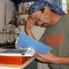
I believe the major health risk in the shop, apart from tool injuries, is wood dust and we have discussed that and dust collection earlier in the series. Solvents and finishes also carry health risks and I will discuss that below, but next on my worry list is flammable materials in an environment where there are sources of ignition – electrical devices, light bulbs, torches, etc. The first picture was taken this morning while I was thinking about this.
This is a chart of NFPA 704 Safety Ratings for materials I commonly use. I keep this posted as a reminder to take appropriate care. For those not familiar with these symbols, the blue represents health risk, the red flammability and the yellow reactivity. Zero is innocuous with 3 being severe. You will see that cyanoacrylate glue with a 2-2-2 rating is up at the top. The other solvents have mostly a 3 rating on flammability. So, the point is that there is a flammability hazard if these materials are not handled properly. There is plenty of warning text on the containers for these materials and they should be read and followed. I make sure the containers I use them in have tight lids and are labeled. To prove it here’s a picture, also taken this morning. Jars like this should be kept closed when not in use. When in use there should be ventilation, they should be kept away away from electrical devices and especially away from any torch activity – and by the way, no smoking.
Cyanoacrylate in droplets is pretty innocuous unless you glue your fingers together, and it is flammable, but with a reactivity rating of 2 it needs some special care. You don’t want to spill a bottle of this. I have done it and watched the rag it fell on start smoking. (Clean up is no fun either.) I now keep the bottle in the base shown below.
This helps avoid tipping over the bottle, which is sometimes necessarily open when in use.
Finally a few words on health risks. Overuse of the word “toxic” is a hot button for me, because this term can be applied to almost anything and so it tends to be ignored or unduly frightening. The NFPA chart above puts most of these materials in class 1, mild skin or respiratory irritants. But even this is a relative term and doesn’t deal with chronic, meaning long term, risks. I suggest that if you are using these materials or any others that may be harmful, that you look up and read the Material Safety Data Sheet (MSDS) for that material so you actually know what you are dealing with and how it might affect you. These are readily available online. Just search for, example “Acetone MSDS.”
There. This is by no means thorough, but now I feel better.
So, back to progress. The ledges on the lower deck have occupied most attention during the past several days. This has been easy work, if a bit tedious. The first picture shows the method for cutting the seats for the ledges in the carlings using a rectangular warding file.
The ends of the 4” X 3.5” ledges are then beveled to fit the seats and glued in. The next picture shows the finished area forward of the main mast.
In this picture the first tier on the starboard side is being left out for improved visibility of the lower hull. Also, since the outer tier on the port side, the tier that involves the lodging knees, will be completely planked over, I probably will leave those out as well. The next picture shows these installed on the starboard side where all the framing will be exposed.
The next picture shows a different view of this area. When these pictures were taken the deck structure had been sanded and rubbed down with steel wool. I didn’t take a picture of the mess that made below.
The last picture shows the entire deck.
The areas left open for viewing below can be seen better in this picture. As much framing as possible is being left open in the forward area over the detailed magazine, but this is becoming harder to see already. I’m glad I have the pictures of it.
I’m still thinking about the next step. It may be to install the stern timbers before getting into internal work leading to the upper deck.
Happy Easter, everyone.
Ed
-
druxey reacted to EdT in HMS Naiad 1797 by EdT - FINISHED - 1:60 - 38-gun frigate
1:60 HMS Naiad 1797
Part 68 –Finishing/Lower Deck Ledges
Posted 4/21/11
I have mentioned finishing with beeswax dissolved in turpentine on a couple of occasions, so maybe some further discussion at this stage, when the finish is being applied to the lower hull, would be appropriate.
The first picture shows this solution being applied with a brush to the lower framing.
The idea behind this finish is to impregnate it into the wood without build-up on the surface, hence the thin turpentine solution. This is made by dissolving solid beeswax in warmed turpentine to a very thin mix. Both these are natural products and I am attracted to them at least partly for that reason. I much prefer the pine-derived turpentine to mineral spirits and other petroleum distillates - for this process at least. The turpentine penetrates the wood and takes the dissolved wax in with it. When it evaporates out, the wax is left. I have used penetrating polymerizing oils, like tung or linseed for many years in various furniture finishing applications, but I prefer the wax for this application. Excess wax left on the surface, especially in tight places where it is hard to rub out, is easier to remove than excess dried oils. A dry Q-tip, bristle artist’s brush or a bit of rag will do the job and if not a bit of turpentine will redissolve the wax and help remove it. This problem with oils can be mitigated by thinning them before application, but they still have a tendency to ooze out later and harden on the surface. Also, since they are cross-linked polymers, they are not easily removed with solvent. Oils also have a more yellow hue that on pear comes out a bit more orange than I prefer.
In the picture below a dry bristle brush is being used to buff the surface and the crevices and also to distribute any excess finish.
As the finish dries, it lightens to a shade in between the finished and unfinished colors in the above picture. Sometimes when first applying this, light spots show up where not all the glue was washed off, so while doing this, I keep a small bit of 400 wet-or-dry paper handy to sand these areas while applying finish. This removes the glue film and it becomes unnoticeable.
Of course once this stuff is put on glue will no longer adhere. The following pictures show the finished lower hull about an hour after application.
More finish at this stage will add sheen. Wiping with turpentine on a damp rag will reduce sheen.
With this work on the lower hull finished, it was time to return to the lower deck – and the ledges. At the time of this writing the lower deck ledges are about 50% complete. The next picture shows how far they have progressed from aft forward.
The inner tier of ledges on the starboard side will be left off and some others, to improve visibility into the lower decks. At least part of the starboard side will be decked, but generally ledges are being installed on that side anyway so I can decide on the decking later - except for the outer tier which will definitely be decked over.
The last picture is just the same area from aft.
Spring chores are starting to cut into modeling time. It will be a few more days, at least, before the ledges are finished.
Ed
-
druxey reacted to EdT in HMS Naiad 1797 by EdT - FINISHED - 1:60 - 38-gun frigate
1:60 HMS Naiad 1797
Part 67 –Rudder Braces
Posted 4/15/11
The last remaining task on the lower hull before applying finish, was the installation of the braces for the rudder. There are six of these. Except for the top one, which was often iron, these were mixed metal – basically bronze. On the model they are made from copper sheet and hollow rod, treated with ferric nitrate to give them a bronzy patina.
In the first picture the stern post is being bearded using a Stanley No. 92 Plane. I find this tool, in spite of its large size, to be very useful for a variety of model tasks. It can be adjusted very precisely to give very thin consistent shavings.
After bearding back each side with the plane, the post was dressed off with a file and the brace slots re-cut – also with a file.
The next picture shows the straps for the braces cut and bent roughly to size.
The stern post widens from bottom to top, so each of these is a different size. These pieces will have a short cylinder made from copper rod silver soldered to it. The next picture show one of these being soldered.
The rod segment has a hole, which will later be enlarged. It is made of two pieces of telescoping rod, which had been previously soldered to form one with a thicker wall. A groove was then filed down one side of this to match the apex on the strap. Individual pieces were then sawed off. The hole allows the pieces to be pinned for soldering and also gives a center point for later drilling. Only one pin out of six got soldered in.
After soldering the pieces were pickled in white vinegar and appear as shown below.
After pickling, larger holes were drilled and the pieces cleaned up with a file. The holes were then enlarged to the final diameter of 3 inches using the very small file and the broaches in the picture. The final sizing in this way allowed the hole location to be adjusted to the center of the strap. This corrected any small misalignment when soldering.
The straps were then cut to final size, drilled for bolt holes, filed smooth and polished. They were then treated by heating and applying a ferric nitrate solution to give them a slight brownish patina. My use of this solution is still in the trial and error phase, but I like the permanence of it and the ability to go all the way to black by varying the heat and concentration of the solution. These parts were only slightly colored. They were then given some additional polishing.
The next picture shows 4 of the six installed.
Small pieces of wood of planking thickness have been inserted under the straps, since this part of the hull will not be planked. Bolts are made from stretched 22 gauge copper wire, cut to a length, driven into predrilled holes, the clipped off and peened over. The long brass rod in the picture was used to maintain the hole alignment so the rudder, when installed, will not bind.
The next picture shows the last brace ready for nailing.
And the last picture shows all the braces installed.
The top brace has been blackened more completely to represent iron. The lower hull is now ready for final polishing up and finishing.
Ed
-
druxey reacted to EdT in HMS Naiad 1797 by EdT - FINISHED - 1:60 - 38-gun frigate
1:60 HMS Naiad 1797
Part 66 –Bolts and Ribband Nails
I needed to get outside of the hull and get some fresh air so I took a day to install the remaining iron nails in the ribbands. I had held off doing this because I intended to use blackened copper and I did not want a lot of handling to rub off the black, but with the decision to use black monofilament this was no longer an issue.
In the first picture I am enlarging and deepening the holes that were drilled in the ribbands before they were installed. The first holes were done in the drill press after marking the frame locations to assure the holes were centered on the ribband. This was covered in an earlier part.
In the next picture the black monofilament, which has been dipped in medium viscosity CA is being inserted into a hole.
These holes go part way through the frame. The filament is moved in and out to help move the CA deeper into the hole.
The blue tape in these pictures is being used to mark the bottom of the thickstuff below the main wale on this side. I may elect to install that planking below the wale and if so do not want to install structural bolts in the location of that planking until it is installed. This is so the bolts will come through that planking, as they should.
Before cutting off the filament the excess CA was wiped off with a bit of paper towel. The filament was then cut off above the surface as shown in the next picture.
When all the bolts on the ribband were installed in this way, they were sanded down to a uniform height with 320 then 400 paper on a sanding stick. This does not make them rounded, but it does level them out. The result can be seen in the next picture.
The area above the uppermost ribband in this picture (actually below it), has been given a coat of wax, but nothing else in this picture has been finished yet. The sheen on the bare wood is the result of sanding to 320 grit and buffing with 0000 steel wool. Steel wool does a great job on hardwood but it is messy to used in the finer grades because it leaves steel fibers everywhere. These need to be blown out of the model, wiped off steel tools and vacuumed off the floor.
The difference in the state of the finish can be seen more clearly in the next two pictures.
In this picture the upper band has had a few treatments of beeswax in turpentine. The next two have been pretty well buffed and beyonf that just some sanding.
I am trying to follow the construction work progressively with finish in a way that will avoid getting wax on areas that may still need to take glue. This is more important inside where lower areas are becoming harder to reach. Once the braces for the rudder are installed all the levels of framing in this picture will be finished.
The next picture just shows more of the bottom.
The lower hull is starting to look finished.
The other work that was done at this time was to finish off the bolting of the lower deck knees from outside the hull. The next picture shows some of that.
There are a lot of copper bolts in this picture that appear to be randomly located. However, most fall into three distinct categories. First are the frame bolts, four at each frame joint, which were put in some time ago. Then, there are the lower deck lodging knee bolts. These can be seen running in a horizontal line just above the lowest ribband in this picture (actually just below it since the hull is inverted). I put in only one per frame. There were actually more. The last category is the lower deck hanging knee bolts. These can be seen running in vertical lines up the frame. One set of six is located just below the center of this photo. I imagine the bolt density in this area would have been about twice what is modeled here.
If all this looks confusing from the outside of the hull, it is.
Ed
-
druxey reacted to oneslim in Echo by oneslim - cross-section
Working on the Rising Wood. I didn't think I could do a clean job of the three faces on the saw. So I used a stop clamped to the miter gauge to make sure the corners were sharp.
-
druxey reacted to davec in Echo by davec - FINISHED - cross-section
My old log was lost, as was the Hannah one. After a lot of thought, I have decided to just restart both where I left off. I didn’t save them, and given the choice between spending time on the computer and spending time in the workshop, it was an easy choice.
I’m looking forward to the workshop in 2 weeks. I redid my keel (pictures below are the fifth redo). I had originally planned to use the previous one, but had made that with the dimensions from the contract, which are slightly different than the plans. When I made the framing jig and it was loose on the keel, I realized I might have other problems down the road, so I made another keel using the wood Greg sent. I have also made the dead flat and dead flat one frames.
I’m going to hold for now and play with my new ropewalk. I don’t want to make any more frames until after the workshop as I think they will be a lot better after.
Dave
-
druxey reacted to Cap'n Rat Fink in Echo by Cap'n Rat Fink - 1/48 - Cross-Section
nd a few more pic's........
cheers Mario.......
-
druxey reacted to dafi in Anchor making
Colored the shaft and the arms for the chamfers ... ... drilled the hole for the ring and most was done. Used my small template to cut the palms ... ...glued in place, cut ... ... cleaned up and done :-)
And here the family shot with all the needed tools that were needed for conception. All the best, Daniel -
druxey reacted to dafi in A small rigging bench
As five hands sometimes are not enough for rigging, I build myself a small rigging bench.
An inclined plane with a pin in the middle ...
... and two hairgrips on a holder. The holder can be fixed also pointing the other direction - or being left off - ...
... and even tiny bits can be worked on with ease :-)
For serving small parts I included a hook on a thread. Turning the part in between the fingers, it is still nicely held under tension and does not wobble around :-)
These are the nice bits one can do with it ...
... and even to be repeated precisely :-)
Gruß, DAniel -
 druxey got a reaction from Jeronimo in HMS Naiad 1797 by EdT - FINISHED - 1:60 - 38-gun frigate
It's so nice to be able to revisit your build in color. Thanks for re-posting it. I'm sure it's memory lane for you as well, Ed.
-
druxey reacted to dafi in Micro Power Splice
Halleluja, praise the heavens!
Why? Because also small things can make me happy :-)
Looking back: A year ago I was already working on the improved gunport lids but had a grandious failure on the gunport tackles:
Looks like a ball of hair straight out of the shower plughole :-(
These days I broused through Gil Middletons wonderful Jotika-Victory and dicovered the splicing that he presents there:
(Edit: Later I discoverd this in use by many others too!)
We proudly present: The Powersplice
It is simple but effective:
Thread - here 0,3 mm - through the ring, neadle through the thread, it is more easy than it looks ...
... make tight, secure with a drop of glue ...
... and once more through it with feeling ...
... pull thight and ...
here we are!
Great, isn´t it???
All the best from a happy Daniel to all of those who showed it before!
-
druxey reacted to gjdale in What kind of glue do you use on your seizings?
I'm another devotee of dilute PVA. When I wanted to re-do a couple of ratlines recently, I simply worked a bit of isopropyl alcohol into the knots with a stiff brush and they came off easily.
-
druxey reacted to dgbot in What kind of glue do you use on your seizings?
Stick with diluted pva glue. If you use ca for your knots the line may become brittle and snap.
David B
-
-
 druxey got a reaction from Sailcat in Cutty Sark by Sailcat - FINISHED - Revell - 1/96 - PLASTIC - Rescue kit bash morphed to Dame Tisane
Good to see you back again, Sailcat. Thanks for re-posting your meticulous re-working of this model.
-