HOLIDAY DONATION DRIVE - SUPPORT MSW - DO YOUR PART TO KEEP THIS GREAT FORUM GOING! (Only 20 donations so far - C'mon guys!)
×

Erebus and Terror
-
Posts
410 -
Joined
-
Last visited
Content Type
Profiles
Forums
Gallery
Events
Everything posted by Erebus and Terror
-
 Hi Matt, Thanks very much for your kind words. To answer your questions: 1: I use a brand called "Fusion". It melts at a fairly high temperature, but it works well. http://www.amazon.com/Solder-Paste-Flux-Silver-Easy/dp/B000VQ9HX4 2. I use a small butane pen torch. It's very underpowered, but it will get up to the melting point needed for silver soldering. 3. I use Jax blackening agent (http://www.jaxchemical.com/jaxshop/shopexd.asp?id=45). It was recommended to me by Druxey and it's a really awesome product (mix it 1:10 with deionized water). I had problems with brass and Blacken-It, so I've switched to using copper for simulating iron. 4. The bolts are Corel brand brass nails (http://www.cornwallmodelboats.co.uk/acatalog/corel-nails.html). They are slightly undersized, but they blacken well (they require a bit of filing and prep, however). 5. The propeller tracks on the Erebus and Terror were made from gunmetal, so I don't plan to darken the tracks at all. 6. All of the copper sheeting was removed on the E and T, as this was expected to be a short duration voyage and likely the last voyage for both ships. Both ships had double planked hulls with extra thick planking at the wales. At the bows, each ships had extra bolsters added to make the stem flush with the hull. On the Terror, an extra layer of 4 inch thick planks was added which extended twenty feet aft. Finally, 5/16 inch iron plating was added over this. With the bolsters, Terror essentially had four extra layers of planking at the bow. Internally, the bow was lined with and additional eight to twelve inch layer of planking. At the load waterline, Terror had more than eight feet of solid oak between it and the ice! It was essentially a wooden ice-breaker. Does that answer all of your questions? Thanks for your interest!
- 346 replies
-
- 3
-

-
- terror
- polar exploration
- (and 2 more)
-
Thanks for the kind words Antony. What are you working on at the moment? I haven't seen your wonderful cross section in a while...that's a real work of art.
- 346 replies
-
- 1
-
-
- terror
- polar exploration
- (and 2 more)
-
Hello Noah, This is a wonderful idea for a build. You're setting a blistering pace! Looking forward to following along. E&T
- 59 replies
-
- 1
-
-
- fram
- polar exploration
- (and 1 more)
-
Thank you for the comments and likes - they are sincerely appreciated. Druxey, I'd pay to see what you would create with a laser cutter! I admit to feeling a little like I was cheating, until I saw the results. Another reason for not feeling overly guilty - my scroll saw recently had a catastrophic malfunction (and is now in the heaven for well-loved, but worn-out, power tools).
- 346 replies
-
- 1
-
-
- terror
- polar exploration
- (and 2 more)
-
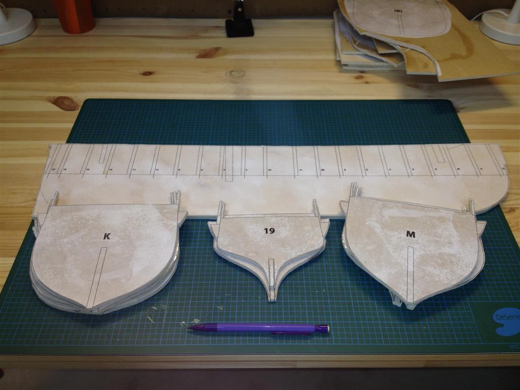
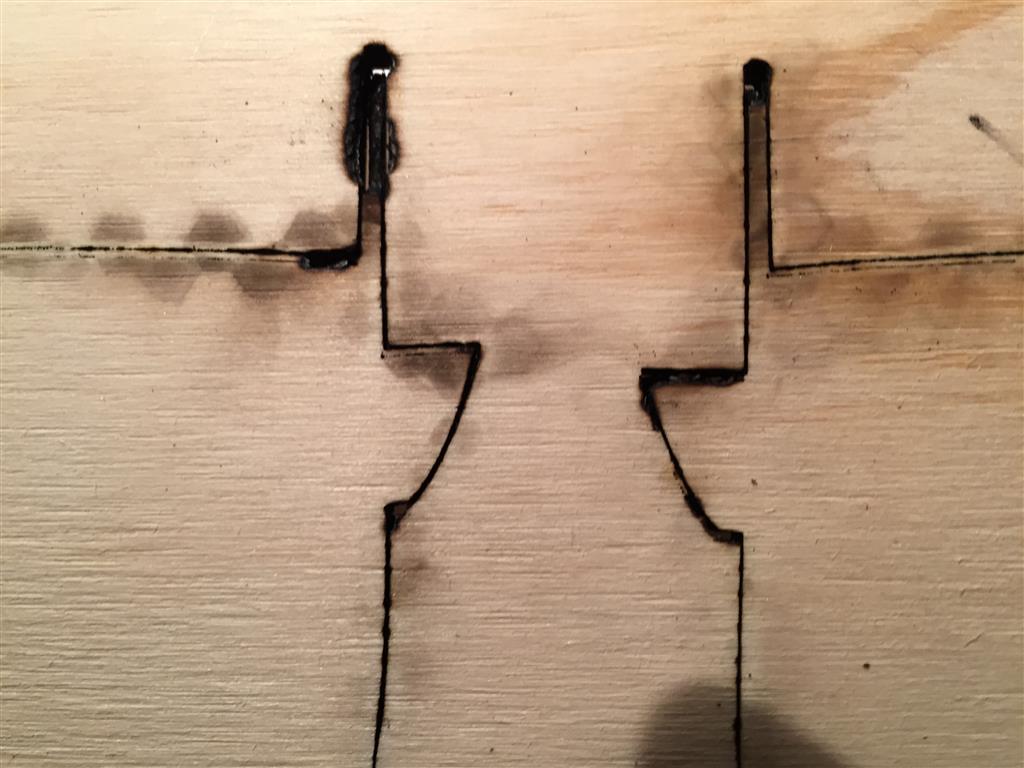
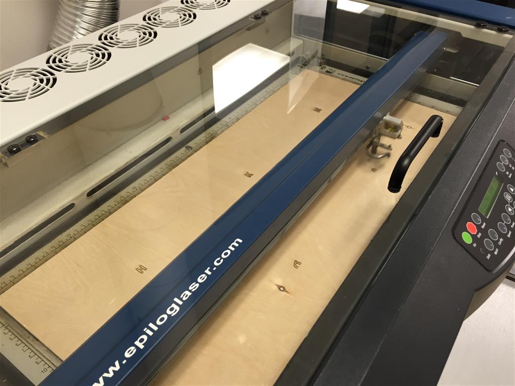
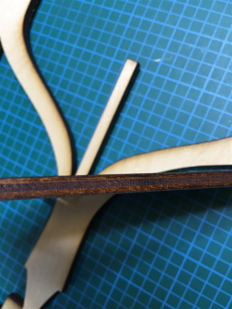
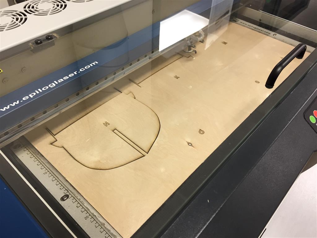
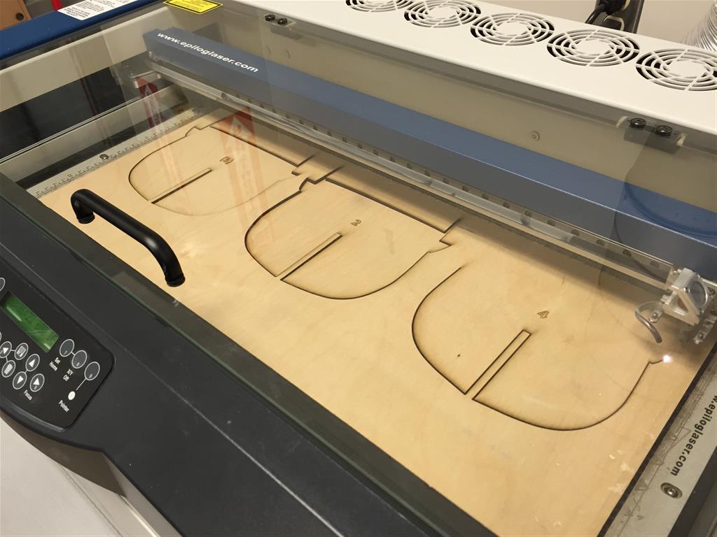
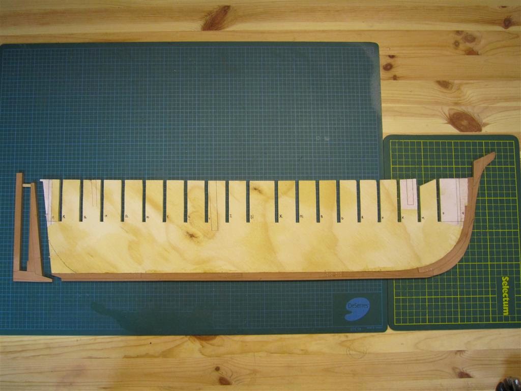
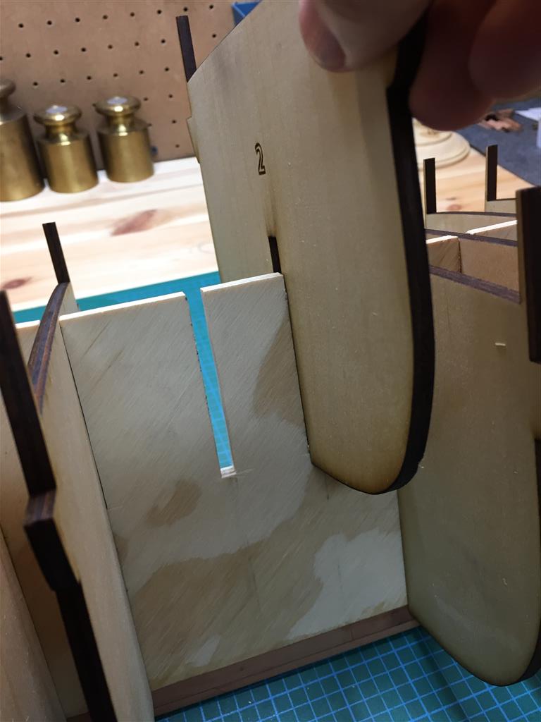
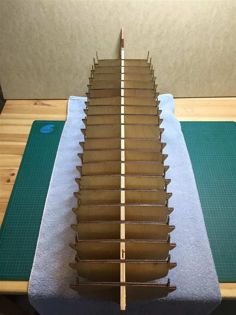
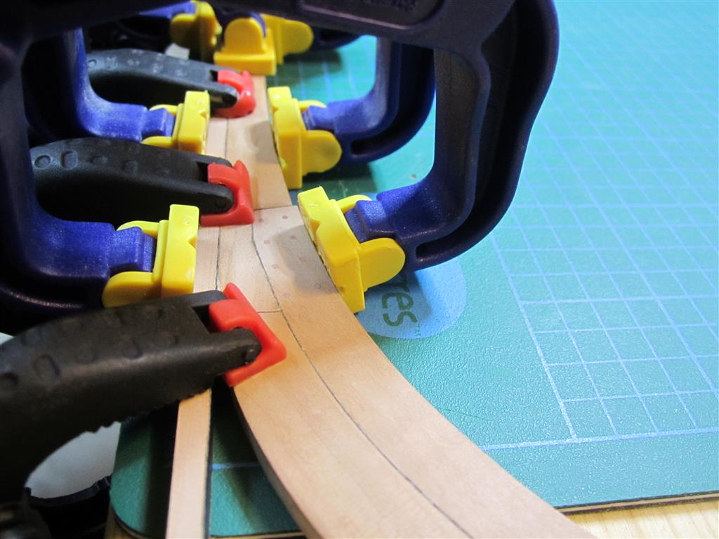
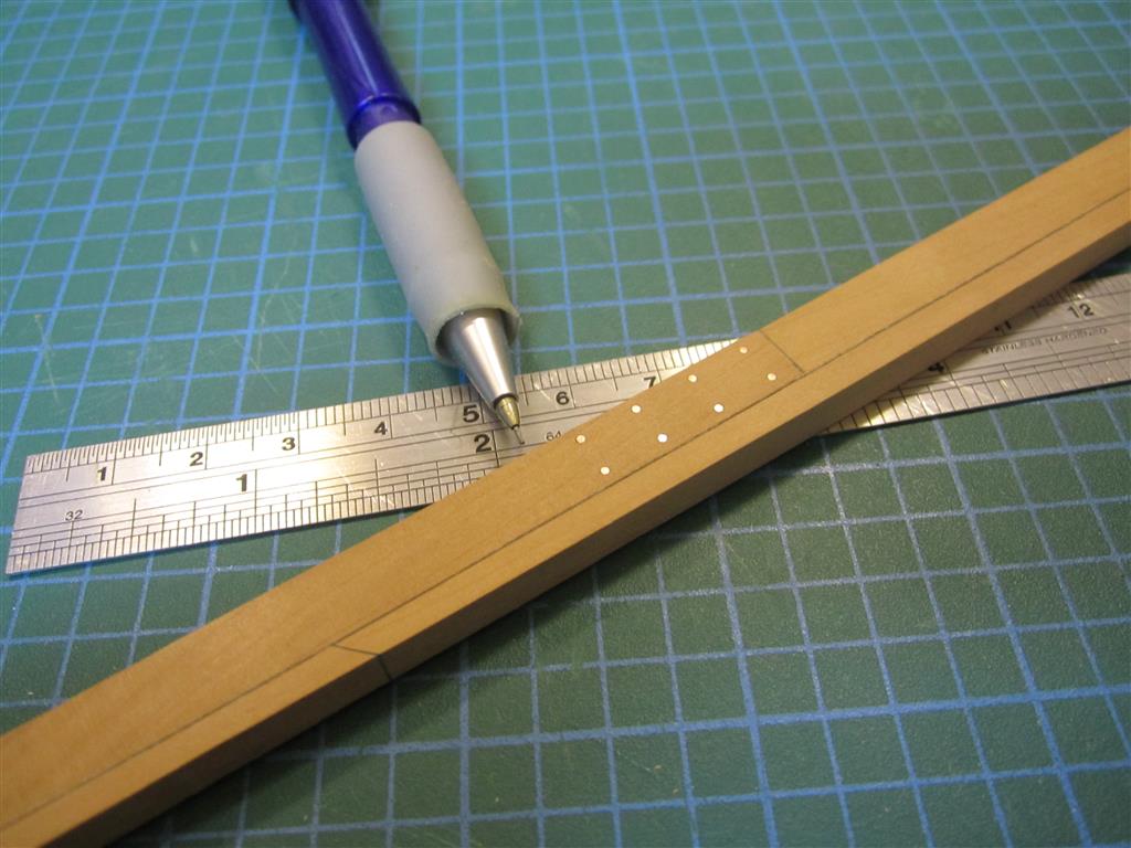
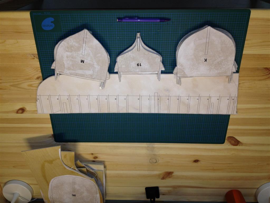
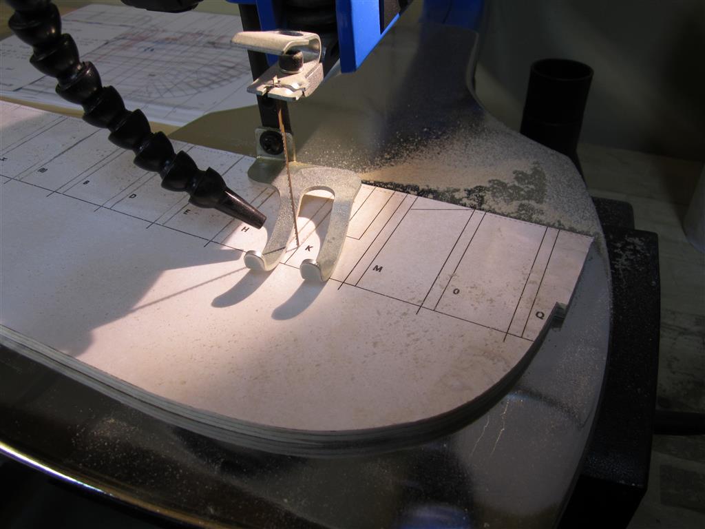
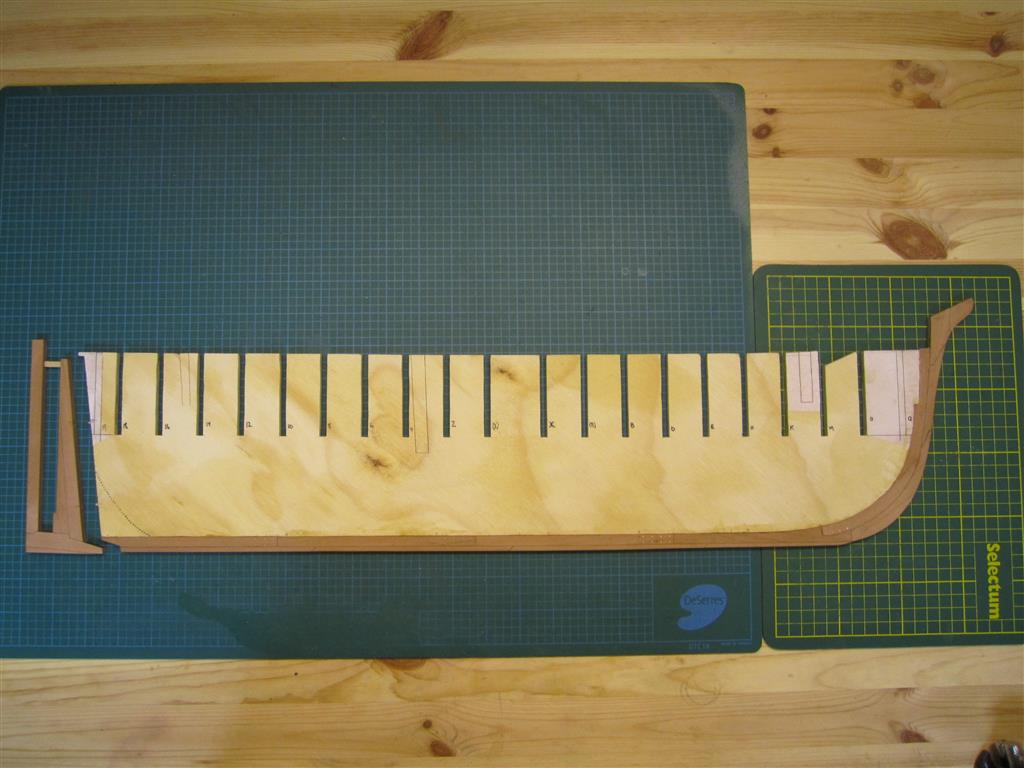
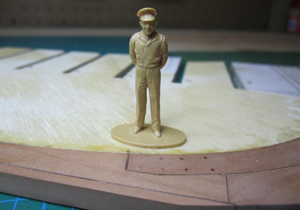
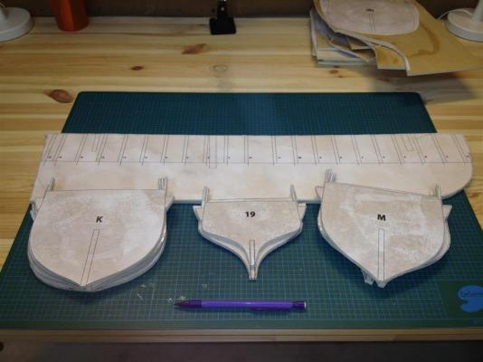
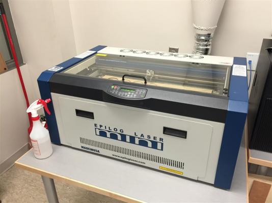
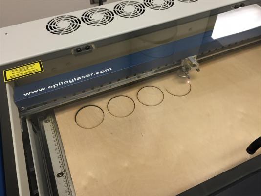
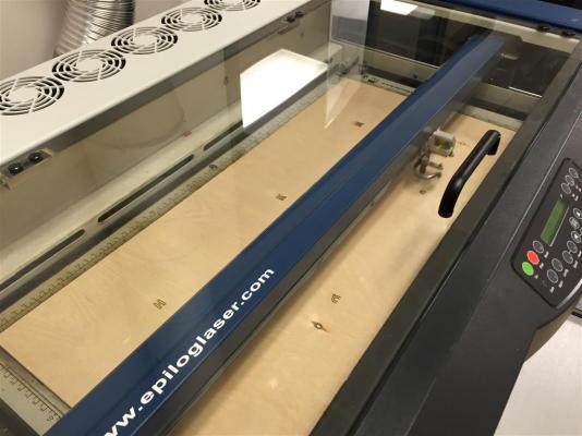
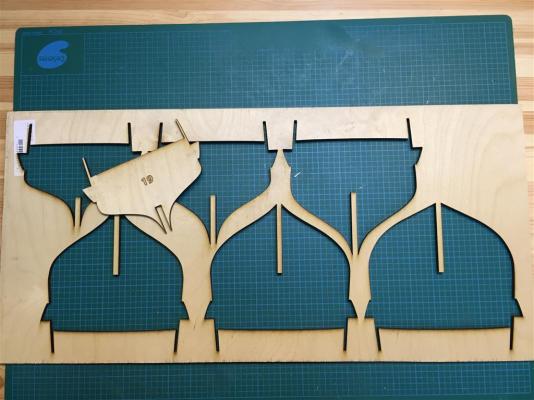
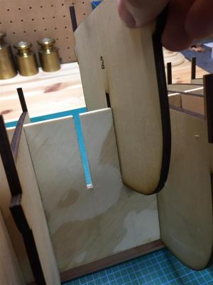
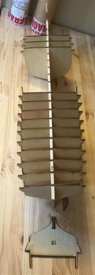
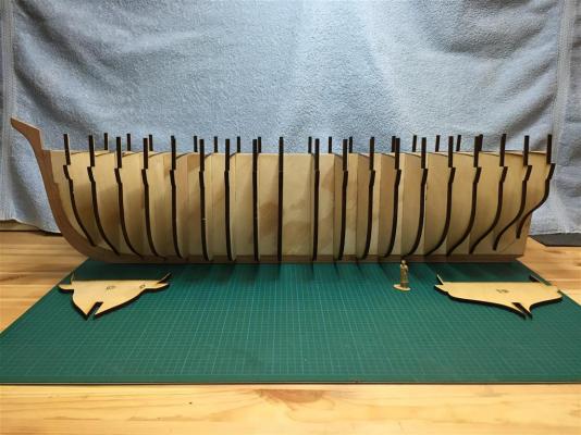
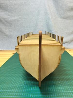
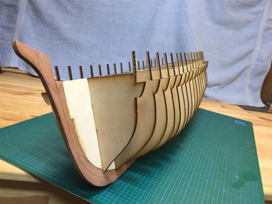
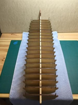
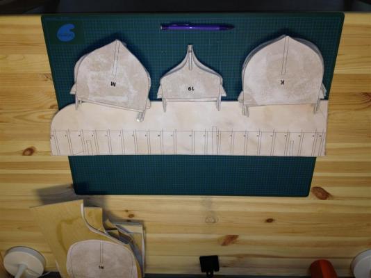
LASER CUTTING TERROR’S BULKHEADS I have arrived at the stage of my build where I am assembling the bulkheads that will give shape to the ship’s hull. I have already created bulkheads for this model using the traditional method – gluing the plans to plywood and cutting them out using a scroll saw. The old bulkheads - cut using a scroll saw (prior to sanding). However, I recently decided to change the way I will construct the bow of the model. I had originally modified the forward stations to account for the extra bolsters and planking at the bow, but I've recently decided to try to build these fittings (as a means to determine how Rice actually reinforced Terror against the ice). This necessitated rebuilding the two most forward station bulkheads. And this gave me an excuse for a whole new mini-project. Following a current trend, my local public library recently opened a prototyping studio, which includes design software, 3D printers, and an Epilogue Mini 24 Laser Cutter. The library allows you to book the equipment for several hours each month - for free. I've wanted to experiment with a laser cutter for some time, and since I needed to make new bulkheads anyway, I decided to recut all of them. My hope was that it would result in a more accurate build. The Epilogue Mini 24 Laser Cutter. The bed capacity is 12" x 24". The cutter works very much like a traditional printer and will engrave (raster) or cut (vector) based on the thickness of the lines shown in the image file (I used high resolution PDFs for this). My first attempt, using factory recommended settings, was somewhat of a disaster, resulting in charred and smoldering wood and unusable pieces (plywood is notoriously difficult to cut because of its inconsistent composition). My first disastrous attempt. Note the burned and charred edges. For my second attempt, I conducted some tests and determined the proper power settings needed to cut 5mm plywood with the thinnest, most accurate, cuts and a minimum of charring and burning [1]. As a test, I cut a series of discs with different power settings. The appearance of the cut edge with the proper settings (no charring). I engraved the station markings on each bulkhead. The machine automatically engraves before cutting. The bulkheads being cut. You can tell the cut was successful if the part drops away from the sheet. A finished sheet. Each bulkhead fits into slots on the false keel. The bulkheads slide snugly into place. Test assembly proceeds. This is just a dry -fit. The bulkheads dry-fitted in place. They need to be properly aligned, but I'm happy with the run already. Mini-Crozier allows us to visualize how large Terror actually was (quite small for a Royal Navy vessel). A view from the bow. This view shows the run of the ice channels very nicely. A top-side view from the stern. The bulkheads are just dry-fitted here and will need to be aligned properly before gluing. I am very pleased with my experience using the laser cutter. The bulkheads are much more accurate than I could have produced by hand, and the process took about a tenth of the time normally required to cut and sand these parts. I will certainly be using it again when I need to cut more complex shapes and components for my build. Footnotes: [1] For those interested, low speed, power, and PPI settings are a must, and the recommended wood settings for the Epilogue Laser will not work on plywood. Your goal should be a setting that will just barely cut completely through the wood, as this results in the thinnest cuts and edges that are browned, but not charred. My settings for good quality 5mm birch plywood were: Speed = 10, Power = 38, and PPI(Frequency) = 150.


- 346 replies
-
- 18
-
-
- terror
- polar exploration
- (and 2 more)
-
Exquisite craftsmanship and display. A true inspiration. Congratulations on your wonderful achievement!
- 662 replies
-
- 2
-
-
- bonhomme richard
- frigate
- (and 1 more)
-
Thank you for the kind comment, Ed. In fact, I have been meaning to thank you for putting me on to copper instead of brass when blackening metal. Since the switch, I haven't had any problems with corrosion - and the blacks are nice and even without flakes. It's also much easier to work than brass. I also need to thank Druxey for introducing me to Jax copper/brass blackener. It produces much more consistent with results at a 10:1 ratio than Blacken-it. I love the stuff.
- 346 replies
-
- 1
-
-
- terror
- polar exploration
- (and 2 more)
-
Thank you all for the comments and "likes", they are very much appreciated! Druxey, that is a good observation, and I'm not looking forward to making the lowest gudgeon straps! I didn't mention this in my post, but the straps were actually bolted through on either side to each other - to provide more strength. The short answer is that I do not know for sure, and it's likely we won't know for some time. I was lucky enough to see a photograph of the Erebus rudderpost in a recent lecture (hence the slight alterations to the propeller rails) and the entire structure appears to be buried up to the position of the seat for the propeller. So, placing them on top of the wood seemed the safest bet until we know for certain - I can always remove and inset them later. Regardless, I think it's possible that they were not inset flush with the wood surface. On Lang's plan they are drawn with a three dimensional effect precisely the same as the gudgeons - giving no indication that they were inset. To me, this suggests Lang's intent was to construct these similar to the gudgeon straps. I've poured over the many models of early screw vessels and while none are precisely like Terror, all the reinforcing straps I've seen are not set flush. The other issue here is that the keel is sided only 10 3/4 inches at this point and removing many inches of wood to make the straps flush might have compromised the strength of the structure. Slim evidence, to be sure. But my main reason for doing it this way was to provide me options later if we actually get a look at this portion of the wreck! I won't be installing the rudder for some time...
- 346 replies
-
- 1
-
-
- terror
- polar exploration
- (and 2 more)
-
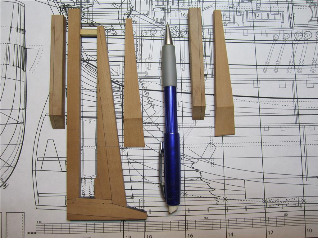
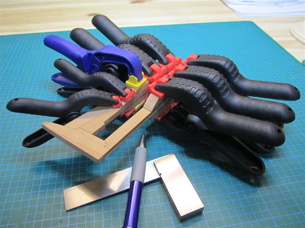
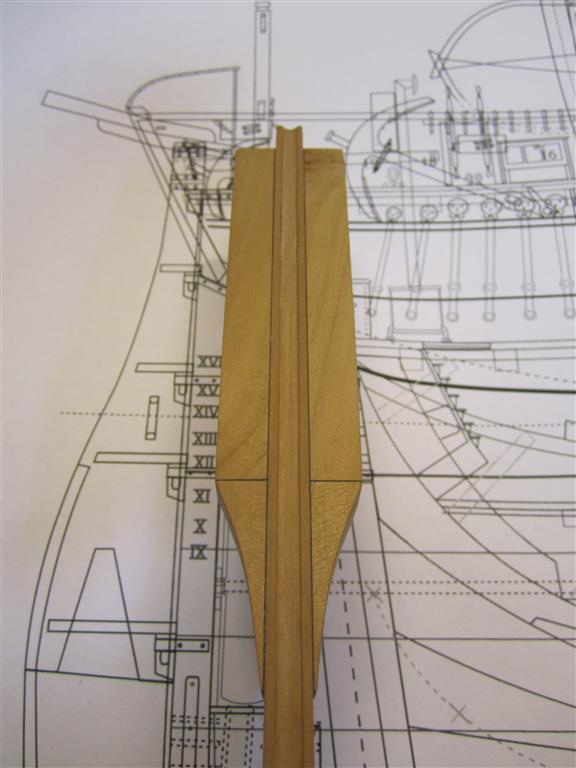
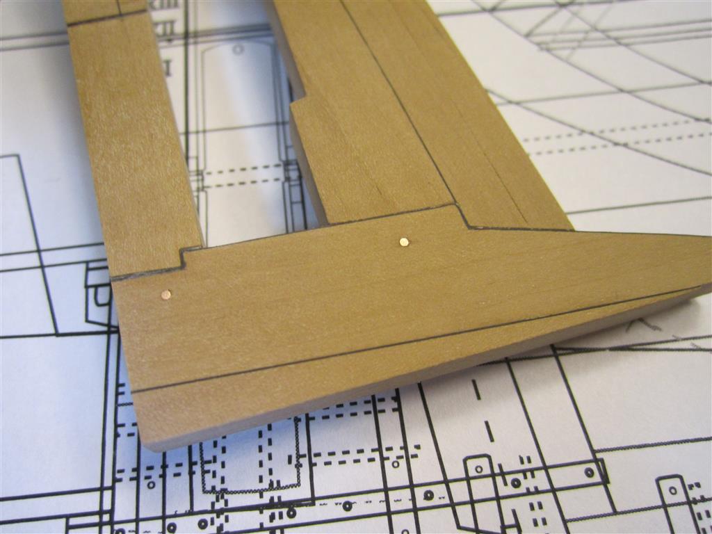
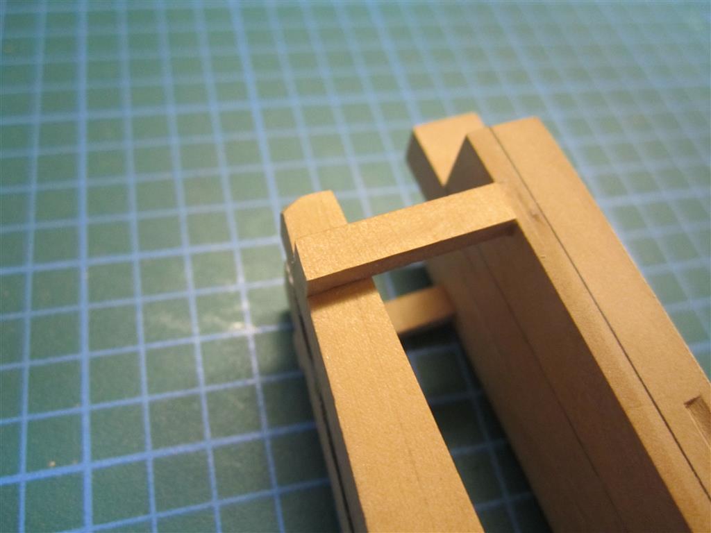
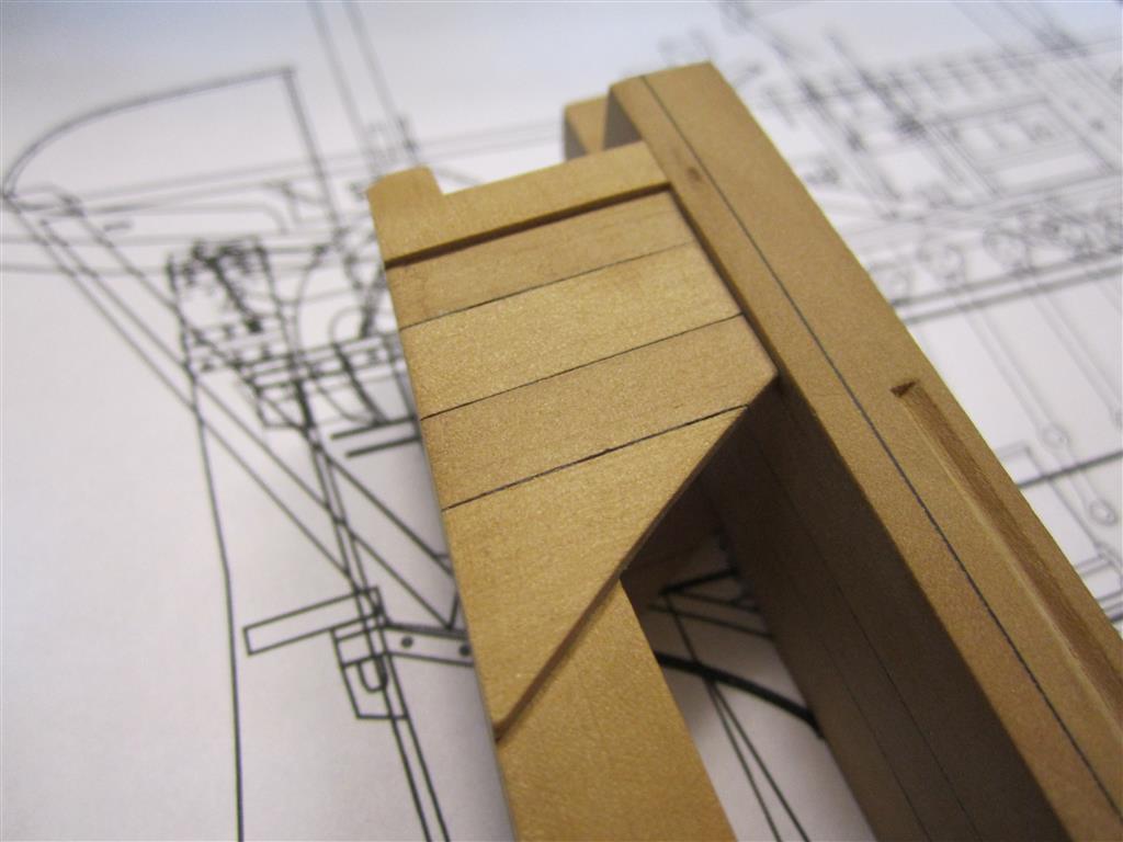
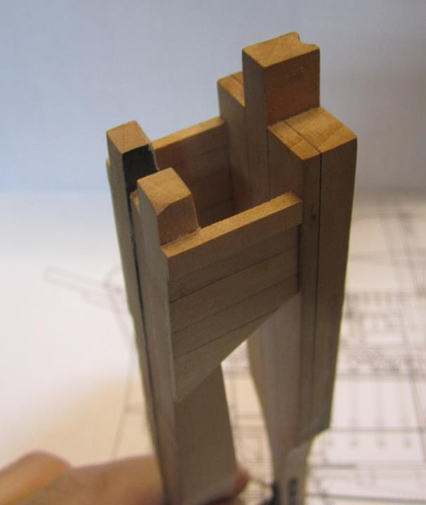
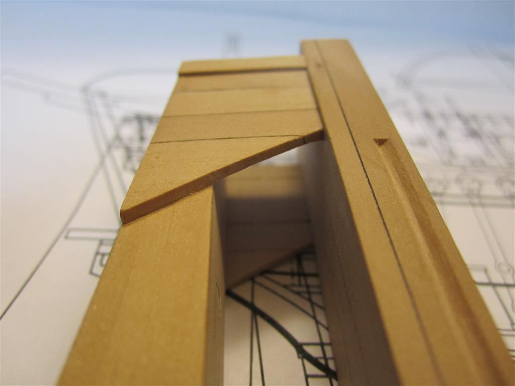
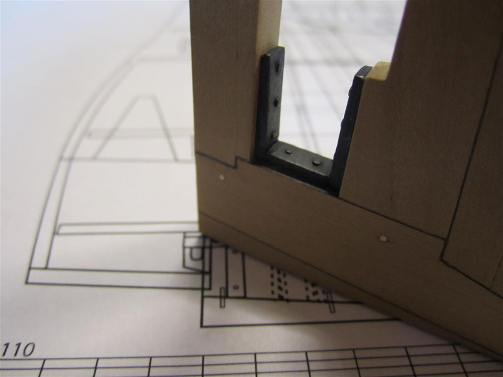
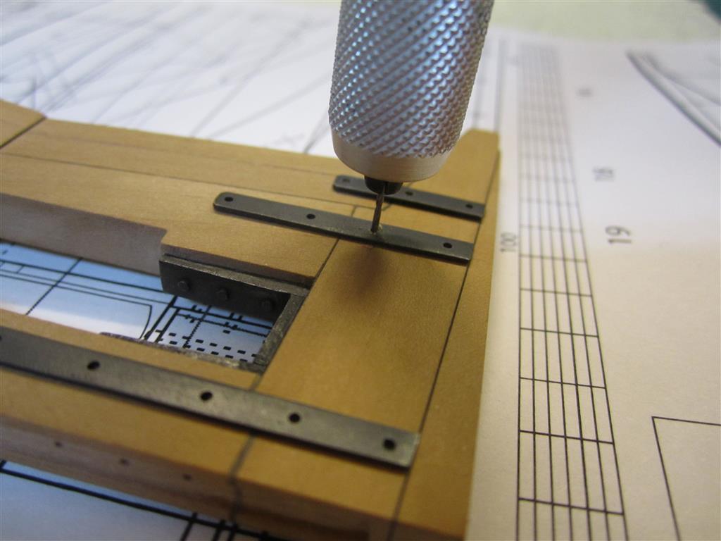
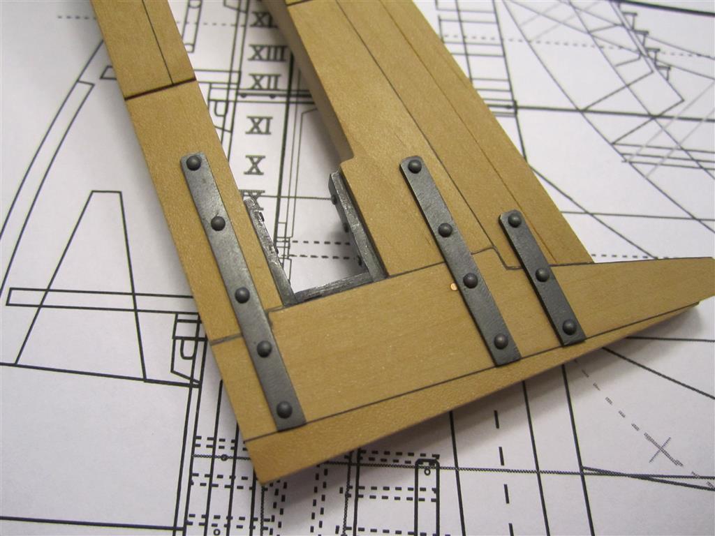
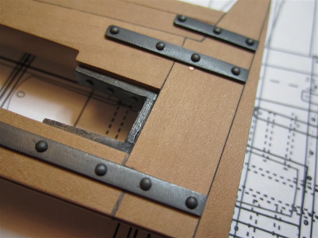
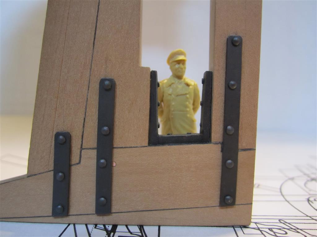
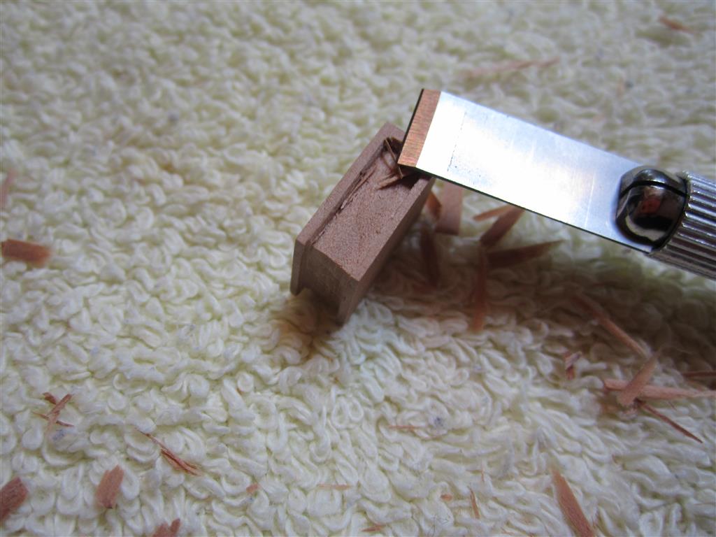
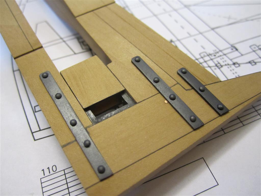
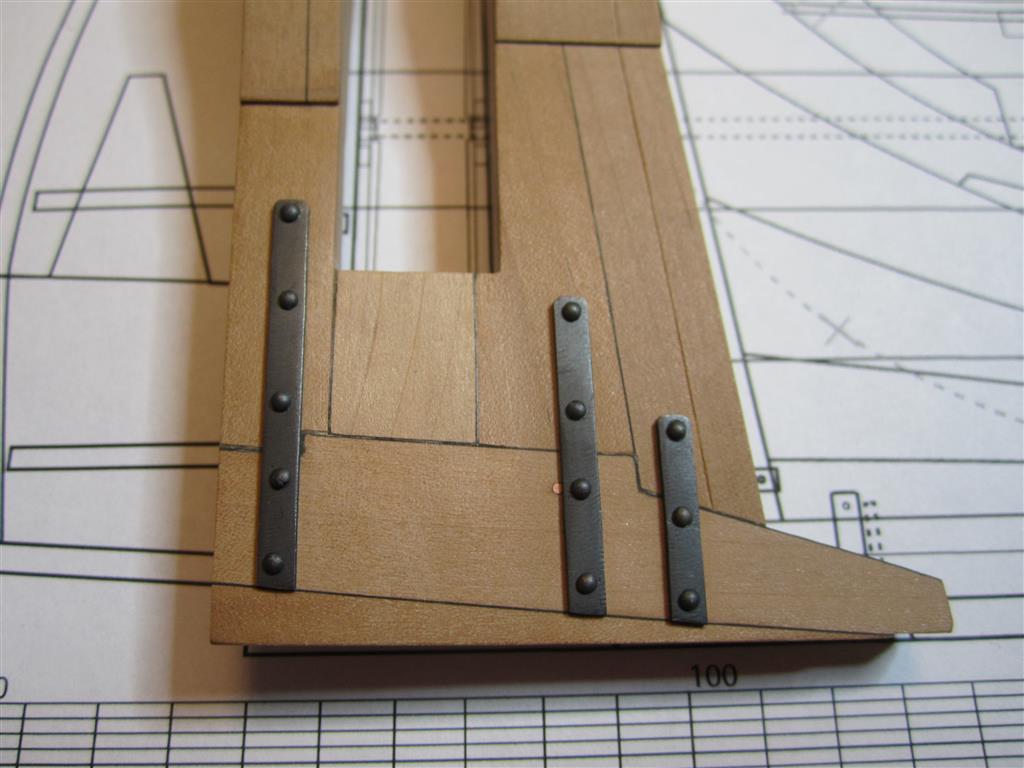
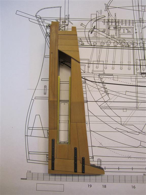
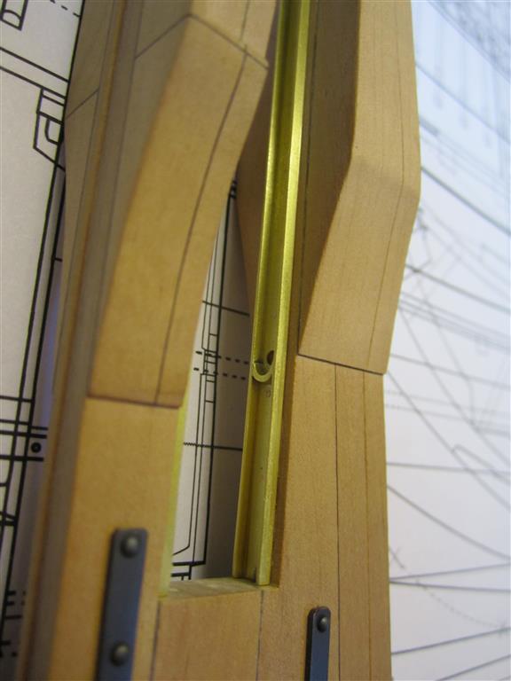
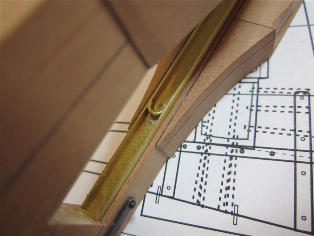
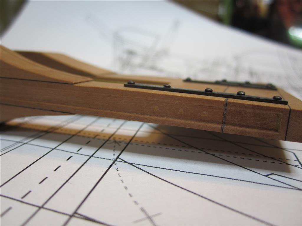
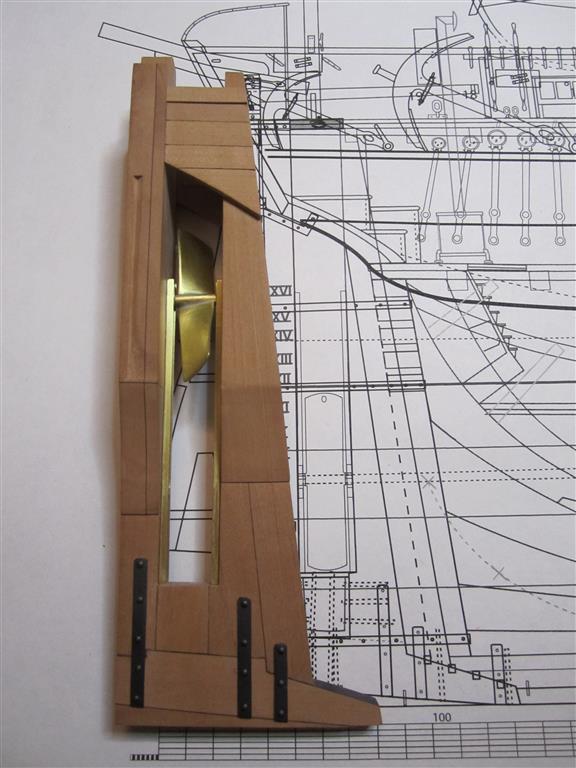
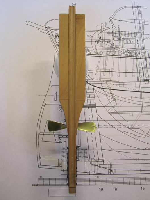
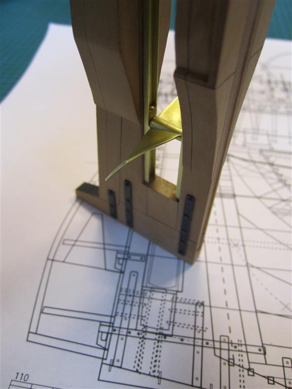
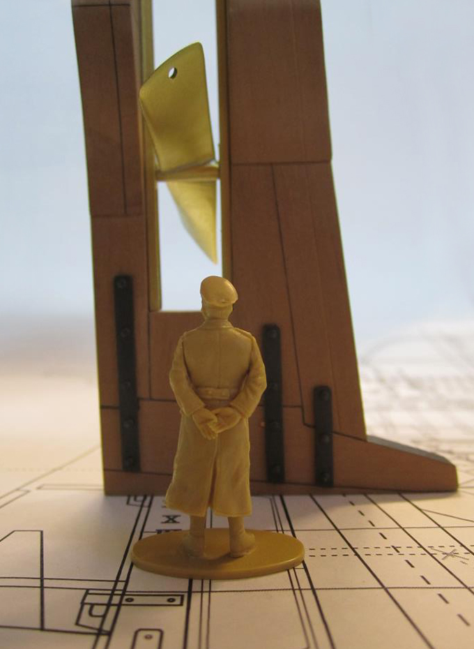
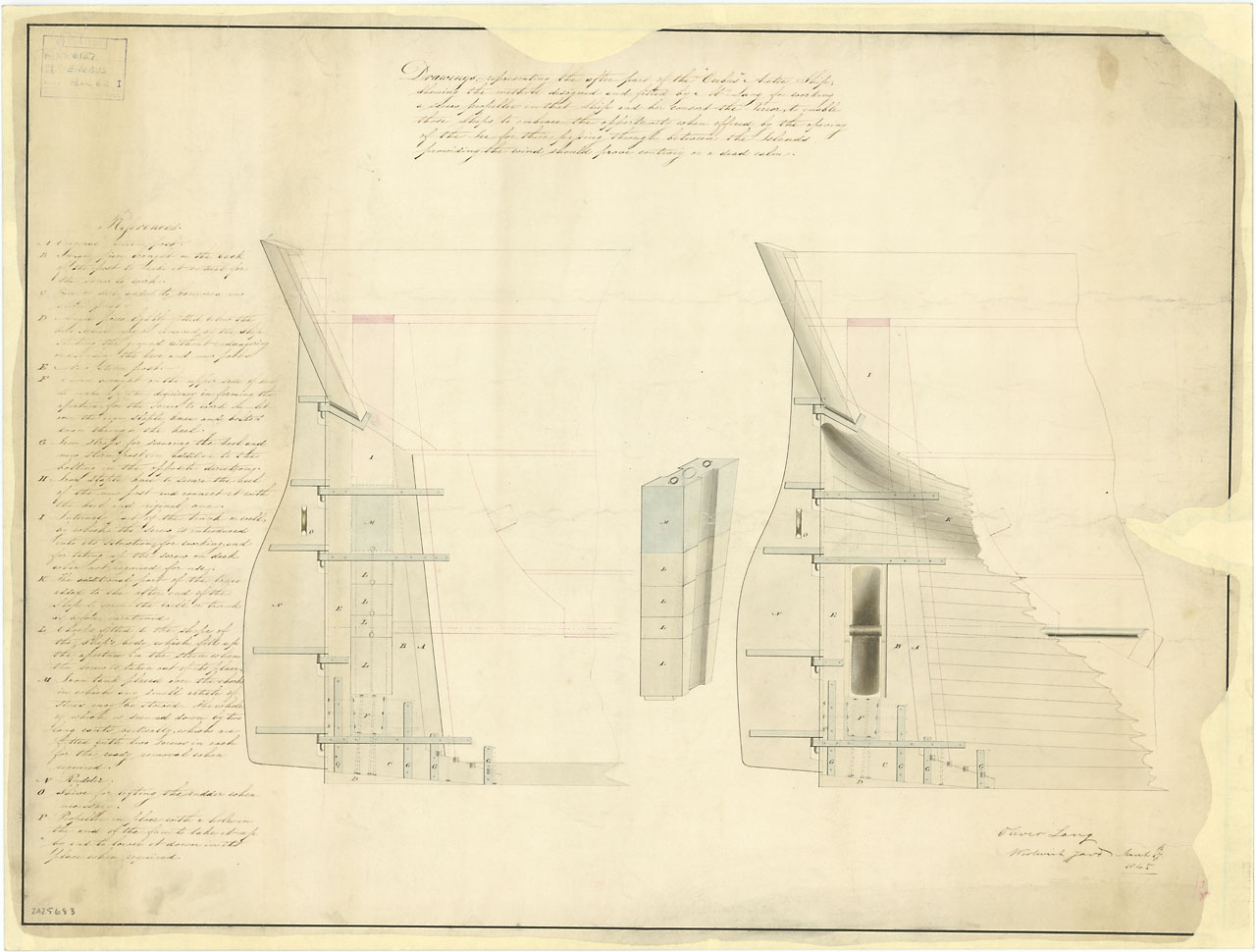
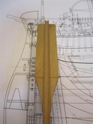
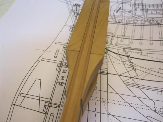
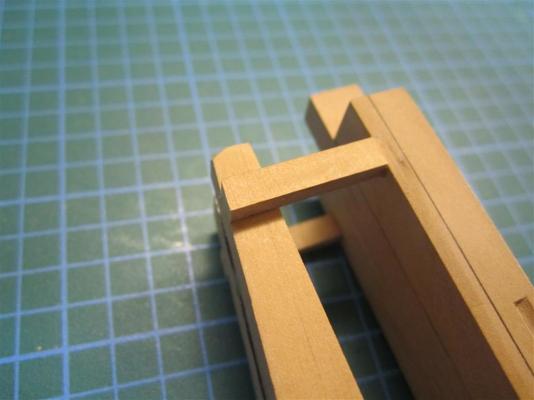
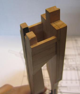
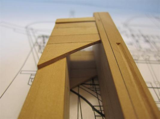
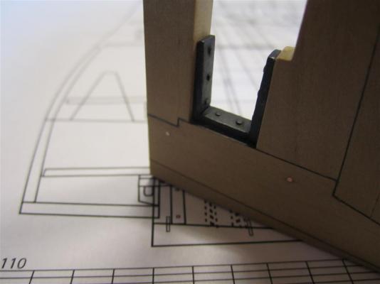
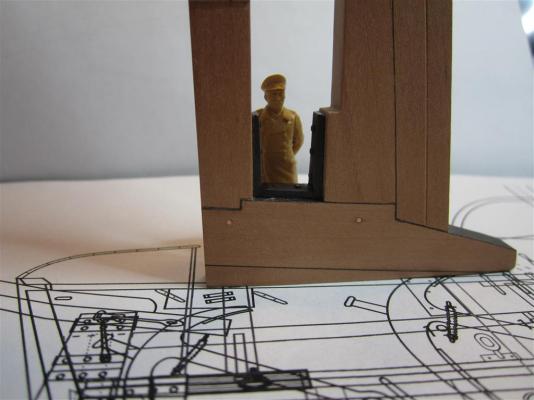
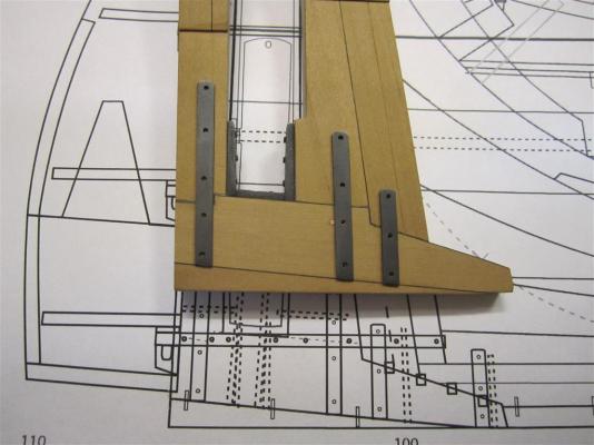
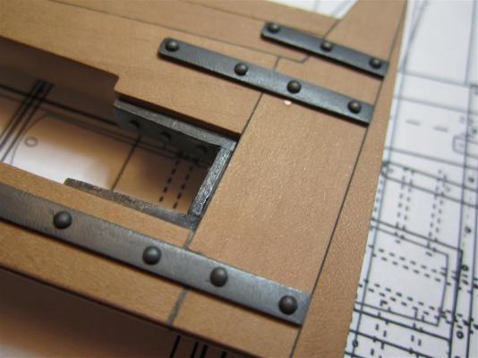
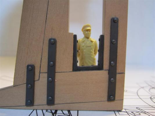
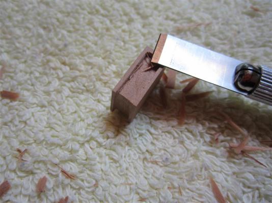
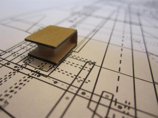
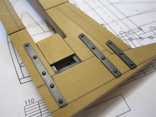
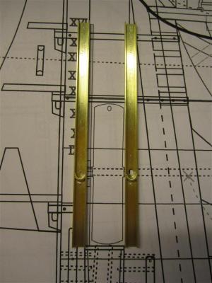
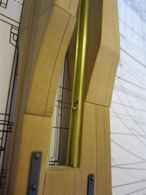
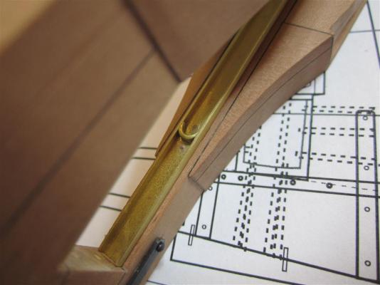
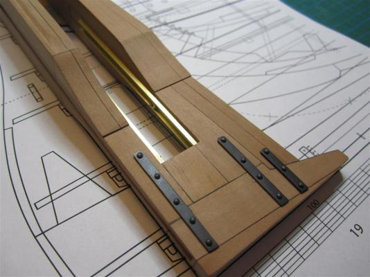
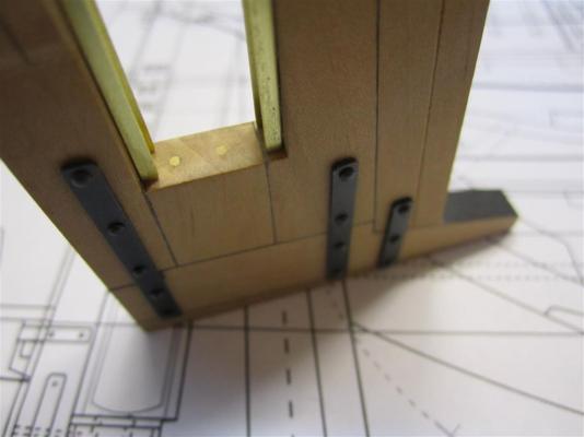
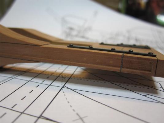
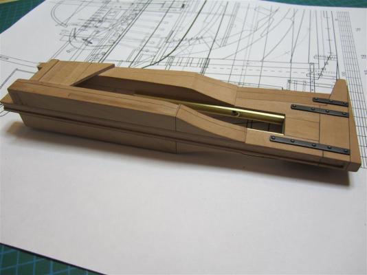
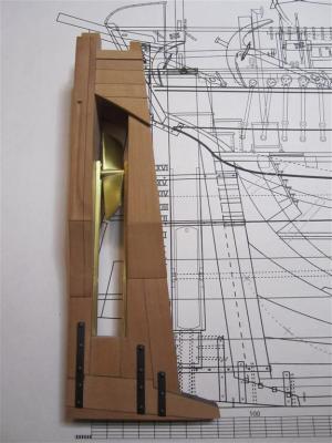
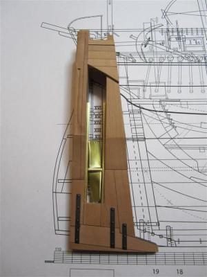
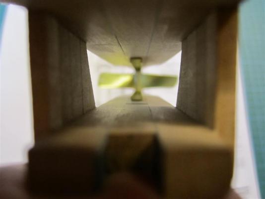
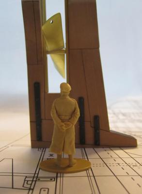
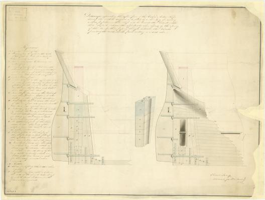
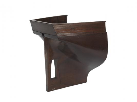
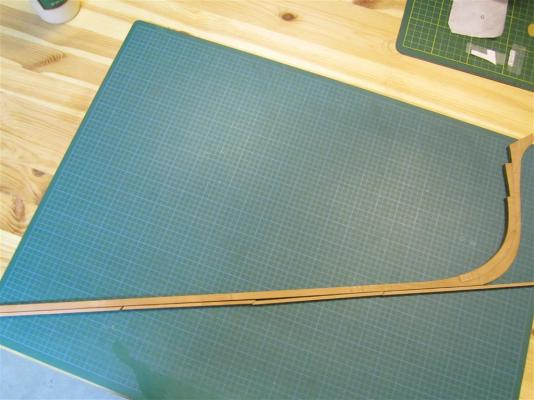
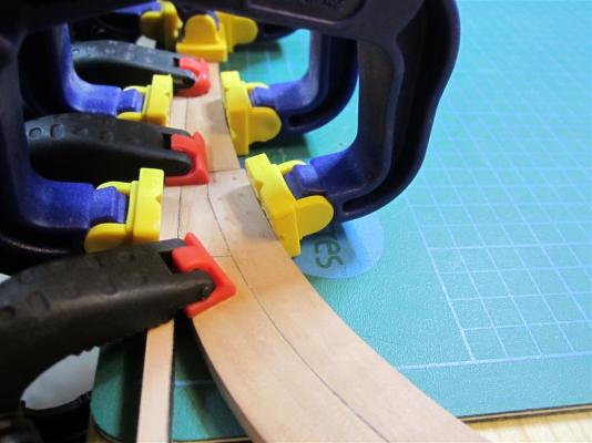
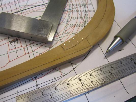
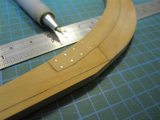
ASSEMBLING TERROR’S STERN (Or, finally some sawdust!!!) I haven't posted an update regarding my model in several months. While I've kept busy with side projects, the real reason for my delay is that I had reached an impasse with Terror’s stern. As I've discussed in previous posts, the sterns of Franklin’s ships were modified in 1845 to accommodate a new auxiliary screw propulsion system – to be used as a time saving device “providing the wind should prove contrary or a dead calm”. There are two sources of data on these modifications: Oliver Lang’s original design plan, and its counterpart, a contemporary model of the design. I had purchased full resolution copies of the plan many months ago, but unfortunately Lang did not include a cross section in his draught. That information could only be gleaned from the contemporary model held at the National Maritime Museum’s storage facility in Chatham. The contemporary model of Oliver Lang's 1845 design. National Maritime Museum, Greenwich, London (SLR2253 [L2251-001]). Used under Creative Commons Attribution-Non-Commercial-ShareAlike (CC BY-NC-SA) license Fortunately, I recently had an opportunity to visit the Chatham model ship facility. Assisted by the expert curators, I was able to study the stern model in detail. It is quite unique, being constructed using a series of carved blocks arranged to conform to the position of major structural and engineering elements of Lang’s design. The information I gathered has allowed me to complete my construction of the stern; below, I’ll reveal the new information I've learned from the contemporary model, while documenting my final assembly of Terror’s stern: 1) The propeller well used to raise and lower the screw was rectangular, almost square-sided, with the sternpost and rudderpost forming the fore and aft sides of the well, respectively. To accomplish this, thick timbers were bolted to the sides of the rudderpost and sternpost. The rudderpost bolsters were much more complex than I originally assumed and were each constructed of at least two pieces, with the lower portions tapering gently to the width of the rudderpost, following the lines of the body plan (see here for my original conceptualization of the design). The stern pieces prior to assembly. The bolster on the left is the old design I intended to use, which was incorrect. The overkill method I used to glue the bolsters to the stern and rudderposts. Thankfully this was just a dry-run (note the older bolster design). The new bolster timbers glued on the rudderpost. Note the groove for the "Lihou" rudder on the rudderpost. I may need to sand the bolsters somewhat to match the run of the planking as they may be slightly oversized - but no by much. Another angle showing the bolster timbers on the sternpost. The NMM model shows that the bolsters on the rudderpost are longer than those on the sternpost. 2) The rudderpost and sternpost were each tenoned into the keel extension, as was typical, but each was secured with a single bolt, which was not indicated on Lang’s plan. Marking the precise position of the tenon bolts. The bolts were simulated with 20 gauge copper wire, precisely the same as that used on the keel scarphs. 3) The propeller well was framed on the port and starboard sides in three distinct sections. The upper section included stout rectangular framing fayed to the deck beams, which formed a ledge for a scuttle on the upper deck. Below this, the well was probably enclosed by watertight planking down to the height of the stern timbers. Because of the construction of the contemporary NMM model, such planking was not shown, but it is unlikely that solid timber pieces would have been used, as these aren’t shown in contemporary models. The heavy framing used to form the top of the propeller well. The upper part of these timbers formed a lip for a scuttle to the well. Planking on the upper section of the well. I've estimated a width of 12 inches. The actual width is unknown. Note that this section of the model will be covered so I haven't simulated bolts or spikes here. A view of the topside of the well. The upper pieces of the sternpost and rudderpost bolsters will be trimmed at a later stage of the build, but are useful for alignment at this stage. 4) A new section, clearly visible in the well of the model, started at the position of the stern timbers. This suggests the stern timbers were bolted to the sides of the rudderpost and sternposts to provide major structural support to the new rudderpost and well. This makes good sense, and Lang’s 1845 stern plan clearly shows the stern timbers as a major element of the design. In fact, these new timbers are substantially more robust than Terror’s original stern timbers, suggesting they were an integral part of the strength of the new structure. Again, this type of structure is supported by contemporary models. The bottom portion of the framing planks were trimmed to match the run of the stern timbers. Note the rabbet on the rudderpost on the right. 5) The lower section of the propeller well was composed of the second layer of hull planking where it ran aft, horizontally. Eventually, the run of the higher planks would have veered away from the straight-sided wall of the well. At this point, straight horizontal planking would have been used to frame the sides of the well. The position where this occurs is marked by a block seam on the contemporary NMM model. Unfortunately, Lang’s contemporary model does not include any of the ironwork used to strengthen the stern, nor does it include the propeller rail/track mechanism. I've based these portions of the model on Lang’s plans and extensive research on other contemporary models and designs. This research is outlined in several blog posts (and here, here, and here). Oliver Lag's stern design. Note the extensive ironwork and the propeller systems. National Maritime Museum, Greenwich, London (ZAZ5683 [J1529]). Used under Creative Commons Attribution-Non-Commercial-ShareAlike (CC BY-NC-SA) license. The iron staple knee glued in place. The knee provided essential support for the rudderpost. Mini-Crozier inspects the staple knee in dry dock. Lang used iron strapping to further reinforce the stern structure. Here they are made from chemically blackened copper. Each strap was glued in place and then the bolt holes were drilled out by hand. Bolts glued in place. These were simulated using blackened brass. Another view of the completed iron work. Mini-Crozier frets over the modifications. The staple knee was protected by a fitted chock bolted to the keel section. I carved this using a simple chisel blade. The finished chock compared to the plans. Image showing how the chock fits over the knee. Unfortunately it had to be glued in place to permit the propeller rails/tracks to be installed. At least I know the knee is there. The chock glued in place. The propeller was raised and lowered using rails or "tracks". These have been modified slightly from my original versions based on new data. Copper bolts were simulated using wire. The rails glued in final position. Note the rabbet on the rudderpost for the second layer of hull planking. The rabbet will be modified to accommodate the precise run of planking when it is installed. View of the rails installed on the sternpost. View of the rails installed on the rudderpost. Another view. Wooden bolt plugs added to the chock. The bolts were "counterbored and plugged". The staple knee was bolted to the rudderpost; these bolts were also counterbored and plugged. I'm not entirely happy with the contrast here and may redo them at a later date. The completed stern assembly. Lowering the screw propeller in place (it raise and lowers - and the propeller spins). The propeller in position. Unfortunately the angle of the photo makes it look slightly crooked, but it is not - is spins freely, with very small tolerances as shown on Lang's original plans. A view from the stern. Another angle showing how the propeller was seated. Looking down the well from the position of the upper deck . Mini-Crozier contemplates how the stern will fare in the ice. How successful was Lang’s stern at protecting the ship from the pack ice? Parks Canada divers are assessing that currently, and with luck they’ll find the answers soon. We know from historical sources that the Admiralty was concerned about the strength of the design, and that while Lang believed the “sternposts” (sternposts and rudderposts) were as strong as those on other ships, he would not certify that the strength of the filling chocks was sufficient to protect the Erebus and Terror [4]. No matter how vulnerable it made the ship, we can suspect that Lang’s radical redesign also altered the sailing qualities of Terror. Contemporary sailing reports indicate that Vesuvius class bomb vessels were rather lumbering and could not carry sail well, and Ross reported that Terror was constantly falling behind Erebus during his Antarctic voyage, delaying and endangering the expedition. Recently, Regina Koellner, assisted by William Battersby, transcribed a letter from Francis Crozier to his friend John Henderson, written shortly after the ships arrived at Whalefish Islands in Greenland. In the letter, Crozier provides a brief report of Terror’s sailing qualities: "Our steering is decidedly improved by the alterations on the counter we now sail much more evenly with Erebus which is advantageous to us in many ways." I suspect that the effective lengthening of the keel to accommodate the propeller allowed Terror to sail closer to the wind, finally permitting her to keep up with the more nimble Erebus. It seems the final conversion of Terror to screw propulsion made her a more capable vessel under sail, an irony certainly not lost on Crozier.


- 346 replies
-
- 23
-
-

-
- terror
- polar exploration
- (and 2 more)
-
Thanks for your insights, trippwj. I've seen the lid from a barrel of flour from HMS Resolute, so I suspect they used primarily barrels. Crozier was so worried about the overloaded state of the vessels that he sent anchors and iron davits home with the transports. The ships are described as having only a narrow path fore and aft, and even the deck plans show fittings to secure dozens of barrels on deck.
- 346 replies
-
- 2
-
-
- terror
- polar exploration
- (and 2 more)
-
Hi Druxey. Thanks for the kind comment. It's been reported that the ships carried nearly 70 tons of flour (combined), meant to last three years. It seems an almost impossible amount of provisions for such small ships.
- 346 replies
-
- 2
-
-
- terror
- polar exploration
- (and 2 more)
-
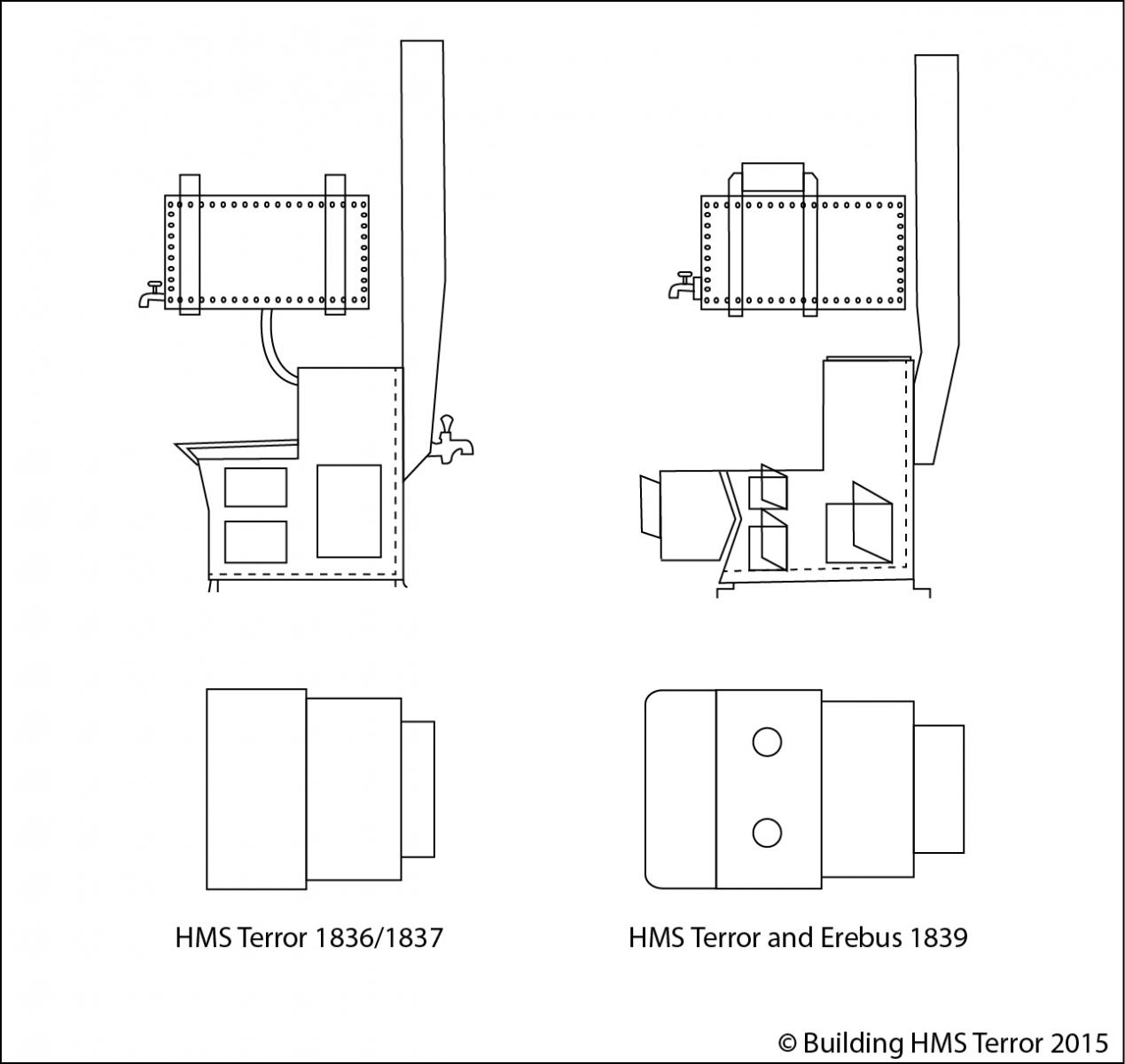
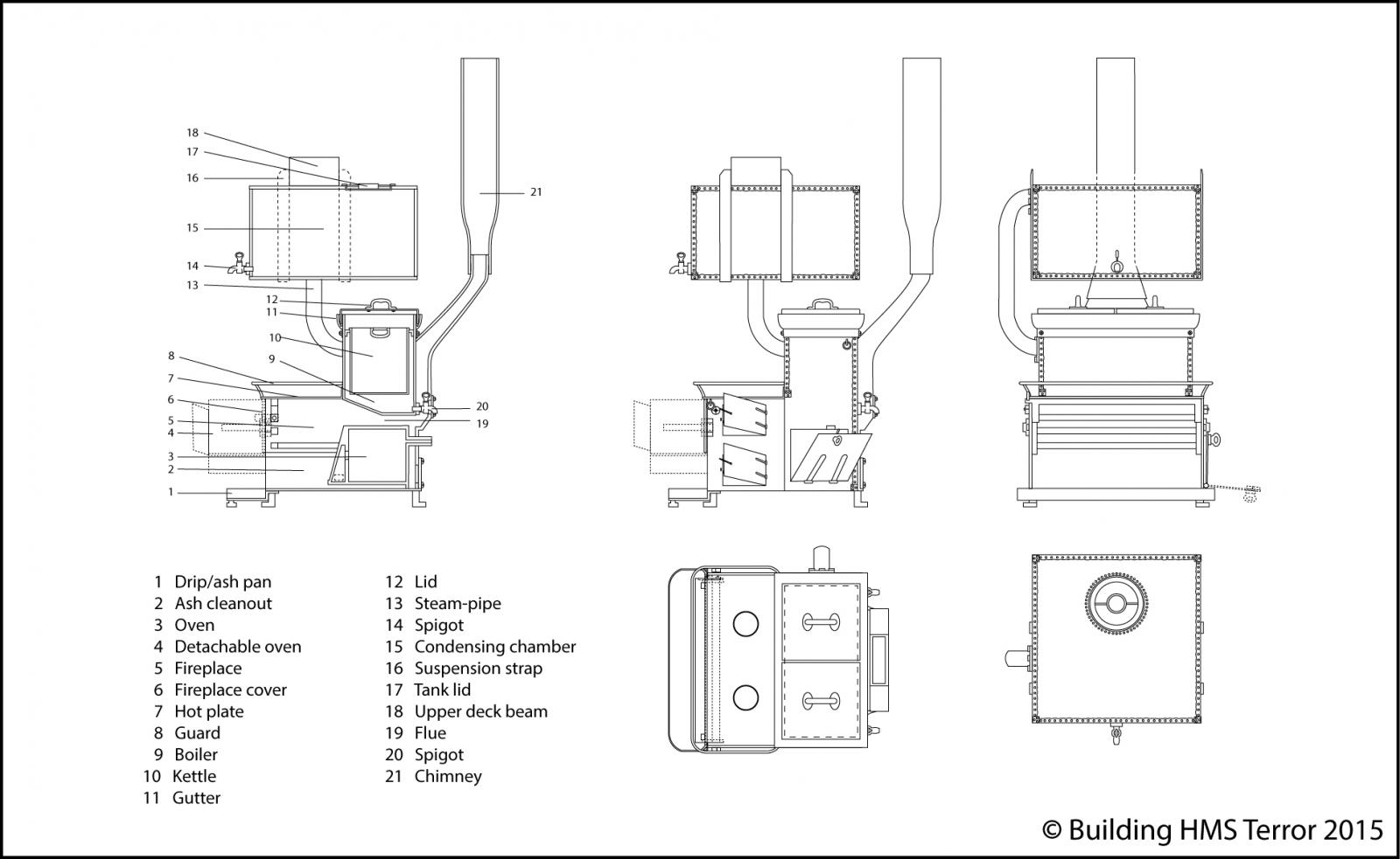
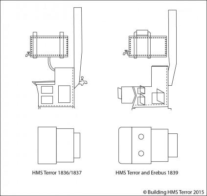
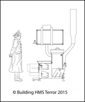
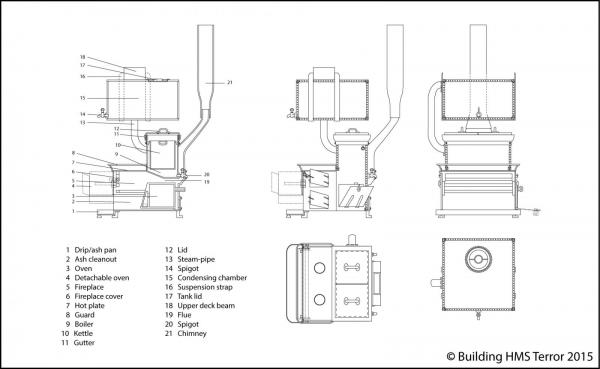
Mr. Diggle’s Galley Stove (this is an abridged version of a post on my Building HMS Terror blog) I haven’t posted in some time, as I have been busy with several exciting side projects, which I hope to reveal here in due course. In the meantime, work continues of my model and plans when I can find time. The stern of Terror is almost completed and I’ll post my progress here shortly. I’ve also recently finished elevations/profiles of fittings located on the forward crew deck, including the sail bin, the mess tables, and crew trunks/benches. One problem with drafting elevations in this area of the ship has been a lack of detailed information on Terror’s galley stove. We know that Terror was fitted with a “Fraser’s patent” stove for its 1836-37 Arctic expedition and that both Erebus and Terror were fitted with these stoves for the 1839-1843 Antarctic voyage. It is widely assumed that the same stoves were used for the Franklin Expedition. Both the 1836/1837 (Terror) and 1839 (Terror and Erebus) plan sets show an iron stove of the same size and shape, with forward facing boilers, a rather large hotplate, and three access doors on one side (starboard). Both sets of plans show a water tank hanging from the upper deck beams directly over the stove, and in the 1836/1837 plans the stove is connected via a short pipe to the tank. However, the 1839 plan set shows an additional box-like projection with rounded corners abutting the front of the stove. The projection has a forward facing door, and seems to be designed to articulate with the stove’s fire place, while being a separate accessory. What this object was has remained a mystery. Fraser's patent stoves as they appear on the two HMS Terror plan sets. Note the additional device attached to the 1839 stove. Comparing the Royal Navy draughts to Fraser’s designs indicates that a patent filed by Fraser in 1822 [1] closely matches the general shape and dimensions of the stoves installed on HMS Terror in 1836 and 1839. Fraser’s stove was intended to be compact and was therefore only suitable for smaller vessels such as brigs and merchant ships. Beyond the narrow width, the major difference between Fraser’s 1822 patent and the Terror plans is the position of the boilers. However, an 1833 engraving of a “Frazer patent sort” [2] stove indicates that Fraser later increased the width of the stove and placed two identically sized coppers side by side, thereby increasing the size of the hotplate at the front of the stove while reducing the size of the oven. This 1833 sketch is in fact very similar to the stove depicted on the 1836/1837 Terror plans. My interpretation of the appearance and design of "Fraser's Patent Stove" on HMS Terror. The plans incorporates scale details from the 1822 patent, the 1833 engraving, and the HMS Terror plan sets. A significant attribute of the Fraser stove was the inclusion of folding or removable plates that could be closed down over the fireplace during bad weather. Previously, ship stoves had to be put out in stormy weather due to risk of fire from stray embers. This seems to have been a critical selling point, and in 1830 Henry Beeston and Company, who held the manufacturing rights, marketed the stoves as the “Fraser’s safety ships’ hearth” [3]. What was the additional device added to the Fraser stoves in 1839? Interestingly, a clue may come from documents relating to HMS Beagle [4]. Navy correspondence from 1831 indicates a new Fraser stove was purchased for Beagle in 1831, at a cost of £ 46.10s. However, it appears that Fraser included an additional device in the shipment, as noted by Captain FitzRoy: “Hamoaze, 24 Aug. 1831. I beg to inform you that the patent Galley Stove made by Mr. Fraser of Shadwell for the use of the Beagle, is furnished with an additional bread oven which I find increases the expense £ 17. As this oven will be of the greatest use in baking bread for the Ship's Company, I hope it will be allowed by the Navy Board without my paying for it myself.” [5] In his later account of the voyage, FitzRoy makes it clear that this additional device was not a standalone piece and articulated directly with the Fraser stove: ”…one of Frazer's [sic] stoves, with an oven attached, was taken instead of a common “galley” fire-place…” [6] Could the accessory on the Terror’s Fraser stove have been a bread oven? Most 19th century iron galleys were designed to accept accessories at the front of the fireplace, including meat spits, racks, and various other attachments. It is possible that the accessory was a bread oven, though it could be another more common cooking accessory, such as a hastener or hot closet. As far as I am aware, only one Fraser stove is known to have survived to modern times, and it is sitting on the lower deck of HMS Erebus, at the bottom of Queen Maud Gulf, in roughly 12 meters of water. Hopefully, this fascinating piece of Victorian technology – which played a central role for the crews on some of the greatest sea voyages ever conducted – will be revealed by Parks Canada in the coming weeks. Terror's galley stove was quite small, as indicated by a scale Captain Crozier. The height between decks in this area was only six feet. Footnotes: 1: Moxon, John, and Fraser, James. 1824. Patents for Improvements in Ship’s Cabouses, etc. The Repertory of Arts, Manufactures, and Agriculture. London: Repertory Office. Pages 268-275. 2. E.W.B. 1833. Apparatus for Freshening Salt Water. Mechanic’s Magazine, Museum, Register, Journal and Gazette. No. 501, Saturday, March 16, 1833. London: M. Salmon. Pages 335-336. 3. 1830. The Law Advertiser, Volume 8. London: J.W. Pagent. Page 465. 4. ADM 106/1346 5. ADM 106/1346 6. FitzRoy, Robert. 1839. Proceedings of the Second Expedition, 1831- 1836, Under the Command of Captain Robert FitzRoy, R.N. Narrative of Surveying Voyages of His Majesty's Ships Adventure and Beagle, Between The Years 1826 And 1836, Describing their Examination of the Southern Shores of South America, and The Beagle's Circumnavigation of the Globe. Volume 11. London: Henry Colburn. Page 18.
- 346 replies
-
- 12
-
-
- terror
- polar exploration
- (and 2 more)
-
Amazing detail. I always look forward to your posts!
-
Holy smokes! Two concurrent models?! I never use emoticons, but this revelation is well worth one. But, a very wise choice for the book, I believe. I'm impressed by your amazing commitment to this project.
-
Thank you for all the comments and likes - they are a continual source of inspiration. I hope to post much more here in 2015.
-
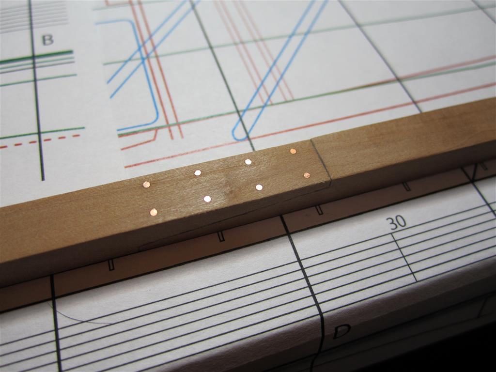
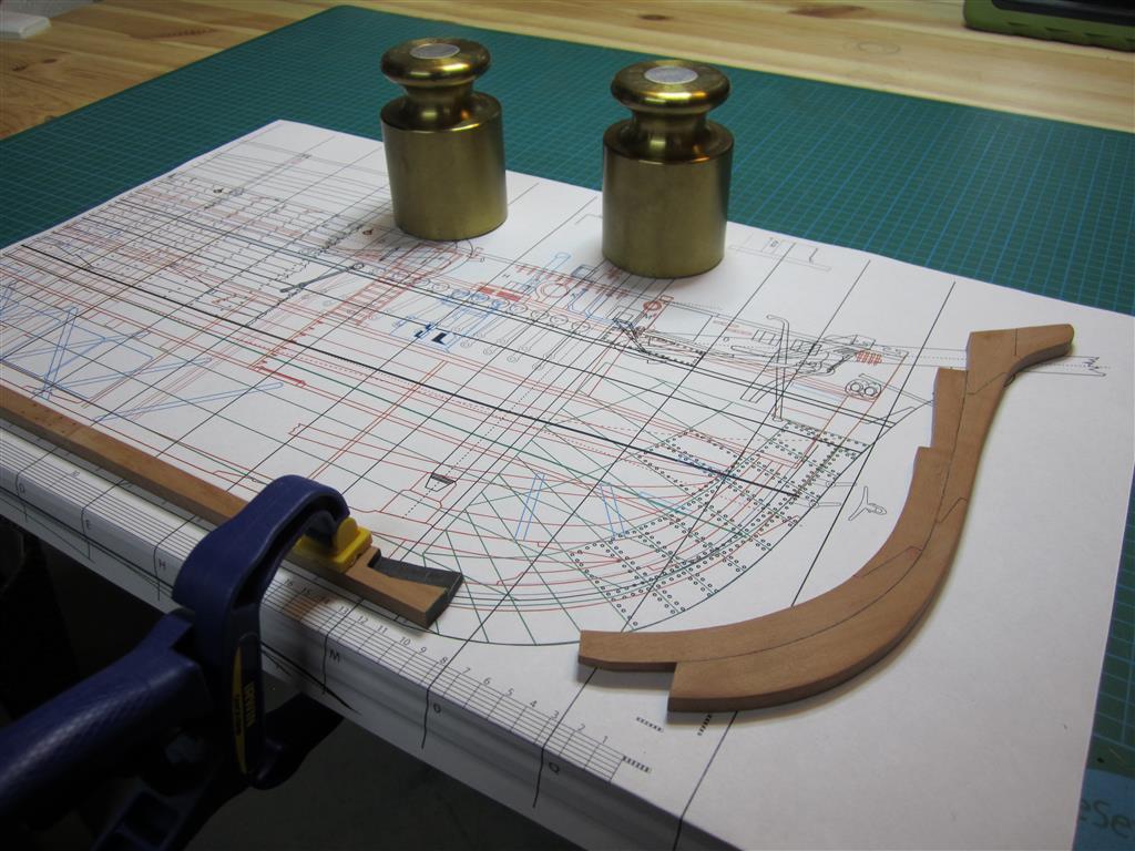
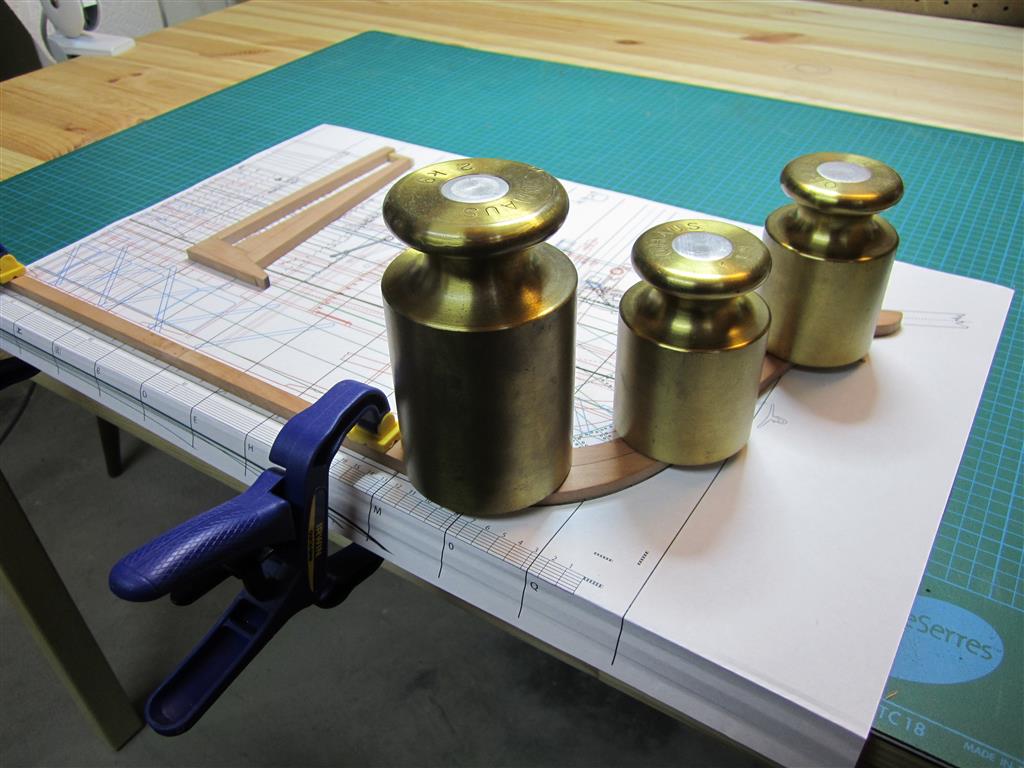
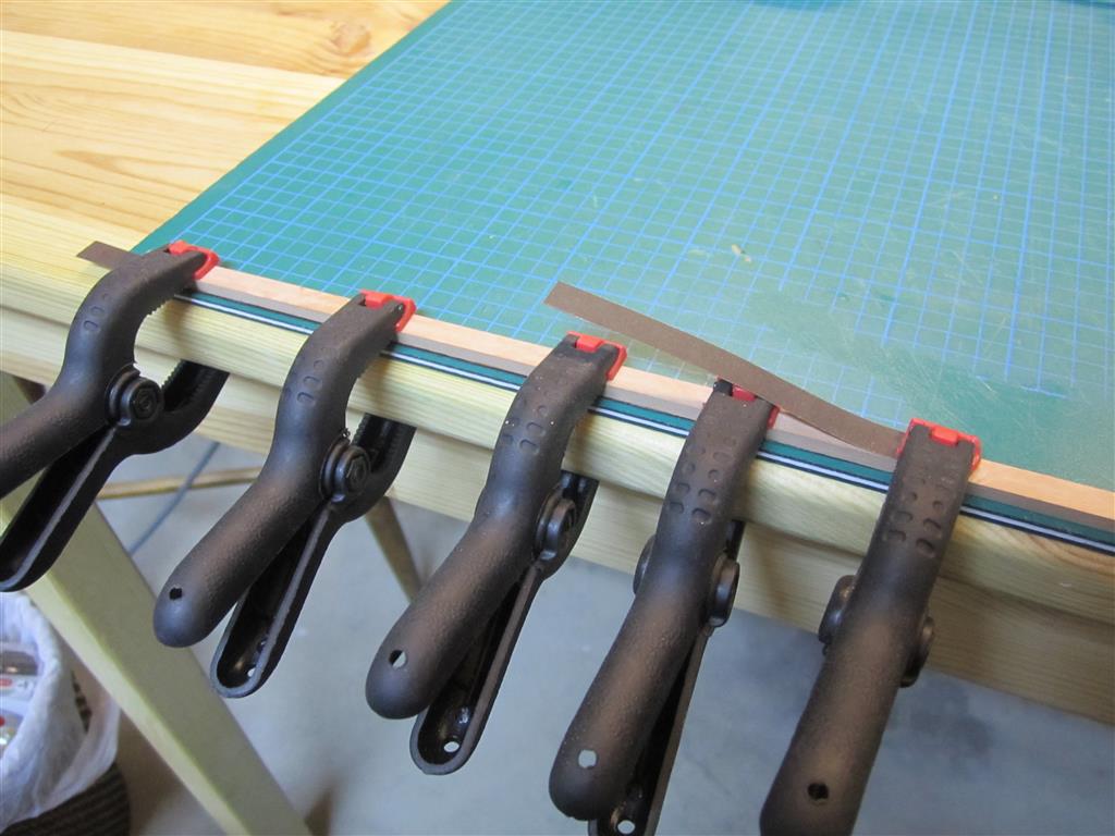
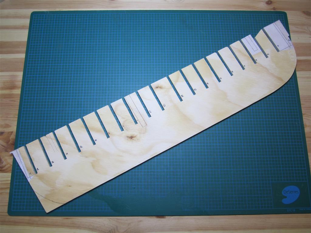
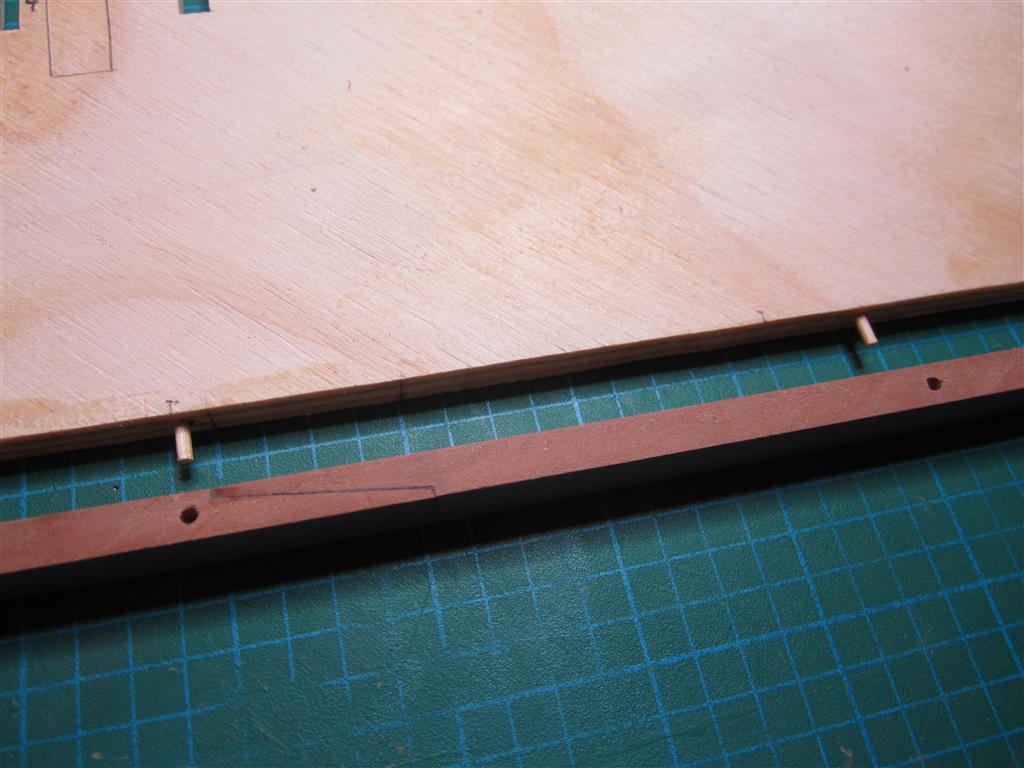
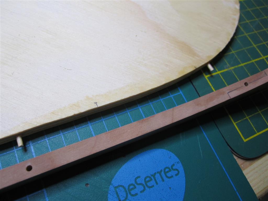
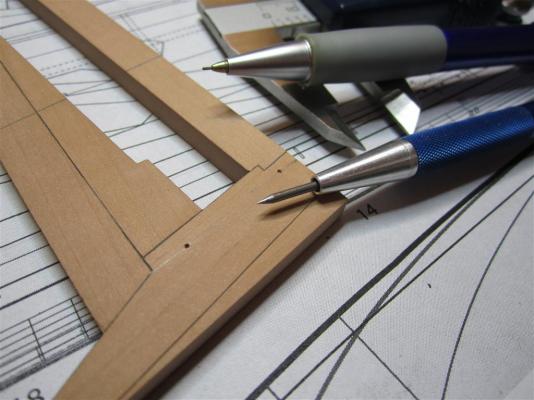
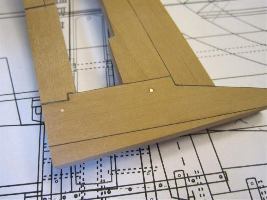
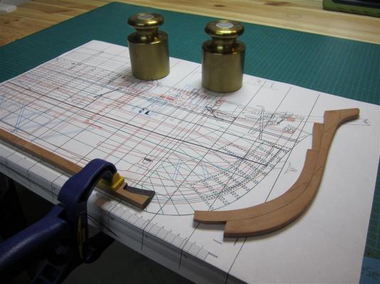
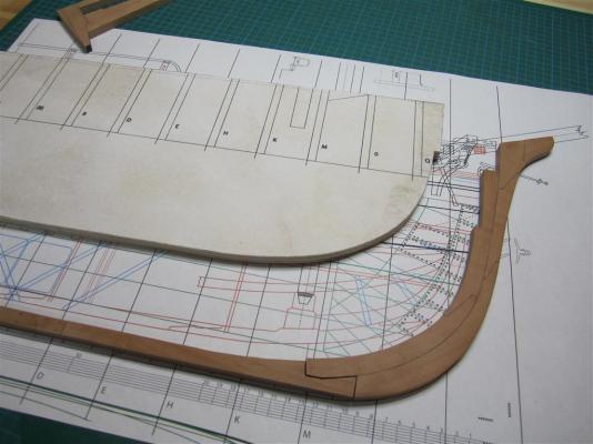
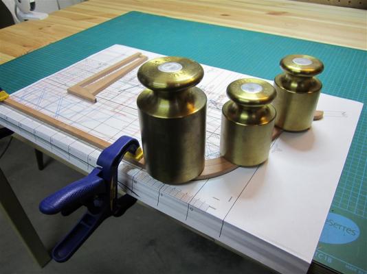
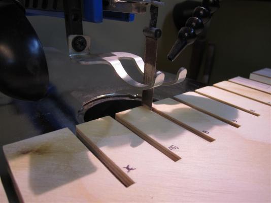
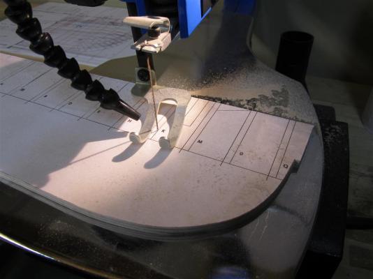
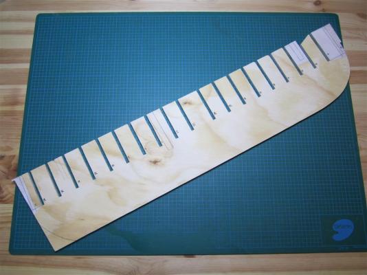
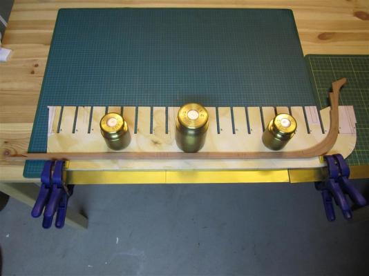
NEW YEAR’S UPDATE It has been a busy year for my project, though, unfortunately, much of my work hasn't translated into recent posts on Model Ship World. As most of you know, my project is really two in one: to create the first accurate scale model of HMS Terror as she appeared in 1845, and to produce the first accurate plans of the ship in her 1845 configuration. I spent much of the year on the latter, having decided early in the year to extend my plans to all decks and fittings of the ship. I completed a significant amount of this work, including the lower deck plans and details of accommodations (I’ve produced much more than has appeared here), and I am nearing completion of plans for the orlop deck and hold, as well as various cross sections. As always, creating these plans is not as simple as tracing the original Terror/Erebus plans, as each requires significant historical research to fill in the many missing gaps. The discovery of HMS Erebus by Parks Canada also had a significant impact on my project. My blog was inundated with thousands of views and I received many dozens of emails from interested readers, researchers, and other enthusiasts. Many came during the exciting few weeks between the time the ship was discovered and when it was eventually identified. I enjoyed these exchanges immensely and they led to a blog post about the structural differences between the ships, which received a very positive response from many readers. The discovery also led to several requests for consultation/information/plans from researchers involved in various media projects. I’m very excited by some of these new projects and while I can’t disclose them all yet, I’m sincerely gratified that my work will appear in formats other than my blog and posts on MSW. One of these has already come out; Canadian Geographic Magazine requested a modified version of my plans showing the most important ship systems. They did not utilize the entire plan, which included a cross section, so I have provided the entire image above. Despite all of this additional work, I haven’t forgotten about my model, and I’ve been working slowly away at it when I can find a chance. Below I outline my progress to date: Each scarph on the keel had 8 copper bolts, 1 and 1/8 inches in diameter (consistent with much larger 36 and 74 gun vessels). I simulated these using 20 gauge copper wire which accounts for a 1.5 inch rove. Gluing the main keel and stem together. Alignment was critical, so the parts were laid out over the plan and clamped/weighted down. Checking the alignment before gluing. The unfinished profile piece can be seen in the background. Gluing the pieces in place. The completed keel/stem assembly with the false keel sections dry-fitted below. Each false keel section was ca. 24 feet in length and 7 inches deep. I originally thought they were attached with staples, but nails were more likely in this era. Gluing black velum to the false keel sections to simulate tarred flannel. Gluing the false keel to the keel assembly. Note the final shaping of the lower stem piece has not been completed. The 1836 plans indicate that false keel thinned as it ran forward; here I've mark off its run prior to final sanding. The completed piece. Unfortunately the fluorescent lights I'm using don't do the richness of the Swiss Pear justice - indeed they make the wood look quite dry and pale when it actually is not. A view of the simple false keel scarphs near the centre of the keel. The false keel was designed to tear away in the case of a grounding and was essential on bomb, merchant, and exploration ships. Note that this is the port side of the keel (fore is on the left). Profile piece and station bulkheads cut from 1/4 inch plywood (no matter what I do I cannot get this picture to display correctly - sorry!). Cutting the slots for the station bulkheads. Deburring with some wonderful scroll-saw sanding strips I purchased from Lee Valley. The profile piece with all the bulkhead slots cut out. The fore and aft slots will be finished after the keel is glued to the profile piece and the mast slots will be removed when the station bulkheads are all in place. The keel assembly and profile piece prior to gluing. The keel was pegged and glued to the profile section. The pegs continued up the stem. The keel assembly glued to the profile piece. Everything is square as far as I can tell - but the clamping required was far too ugly to show here! The stern assembly will be fitted when the bolsters for the propeller aperture are added and will need to be glued in the vertical position. Captain Crozier inspects the boxing.


- 346 replies
-
- 21
-
-
-
- terror
- polar exploration
- (and 2 more)
-
Beautifully done, Rusty!
-
I marvel at your speed and precision. I simply cannot work that fast and do anything credible! I'm sure experience and technique goes a long way, but talent must certainly be part of your amazing progress.
- 3,618 replies
-
- 2
-
-
- young america
- clipper
- (and 1 more)
-
I continue to learn so much from your posts. Thanks for the care you put into them.
- 3,618 replies
-
- 1
-
-
- young america
- clipper
- (and 1 more)
-
Let's talk 3D printers.
Erebus and Terror replied to Keith_W's topic in Modeling tools and Workshop Equipment
Thibaultron, one of the great new things you can do is use Photogrammetry software to capture a 3d model of an existing real locomotive and then print it. A few great free apps are available for this, like 123DCatch. This might be a real solution to those hard to find models. -
Let's talk 3D printers.
Erebus and Terror replied to Keith_W's topic in Modeling tools and Workshop Equipment
I honestly think the wooden kit companies will be fine. Until the printers can print in wood, we'll still need to make sawdust. Revell and Tamia need to be worried, and I think they should shift their business model towards providing higher resolution digital models for people to print. But the wooden ship kit companies won't really be affected by this - just as they aren't greatly impacted by Revell and Tamia bows -
Let's talk 3D printers.
Erebus and Terror replied to Keith_W's topic in Modeling tools and Workshop Equipment
I use a MakerBot 2x printer at work, and I'm impressed at what it can do, though the resolution is not appropriate for anything 1:48 scale and smaller. Eventually, the technology will easily be capable of producing every part needed - and it will likely all be available for free on the internet. Many will want to build their models this way and a very large and creative community of modelers will design and share the very finest and most accurate parts. It will be a fascinating time for the hobby, with 3D Digital artists competing for the first to create and share the finest models for the printing community. Many will sell their 3D digital models. However, I sincerely believe that it will not detract from the work of the dedicated hand-builders who seek the challenge of creating with real wood and metal. 3D printing will be a boone for the plastic builders (and a nightmare for plastic kit companies). Those who like to make sawdust and metal shavings will face the same old problems and reap the same rewards. -
Thank you all for the kind words. David, I admit that I bite my nails every time a new photo is released. I've made a lot of inferences, and while most of them are informed by research, they could be wrong. So far it seems like I'm doing okay, but it could result in a major problem if I build a piece that is later shown to be inaccurate. No more fittings for me for some time! That works as I have a lot of superstructure to build!
- 346 replies
-
- 3
-
-
- terror
- polar exploration
- (and 2 more)
-
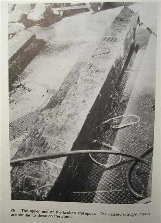
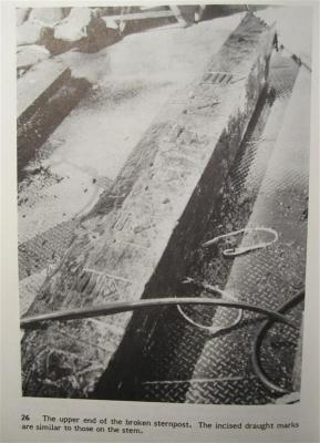
Beautiful Remco! In regards to your previous post on the draught marks, I wanted to show this (an image taken from the wonderful The Excavation of the Machault: An 18th-Century French Frigate). Your draught marks look like a perfect replica!
- 1,215 replies
-
- 6
-
-
- sloop
- kingfisher
- (and 1 more)