HOLIDAY DONATION DRIVE - SUPPORT MSW - DO YOUR PART TO KEEP THIS GREAT FORUM GOING! (Only 13 donations so far - C'mon guys!)
×

Erebus and Terror
-
Posts
410 -
Joined
-
Last visited
Content Type
Profiles
Forums
Gallery
Events
Everything posted by Erebus and Terror
-
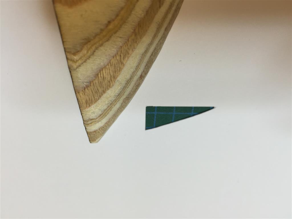
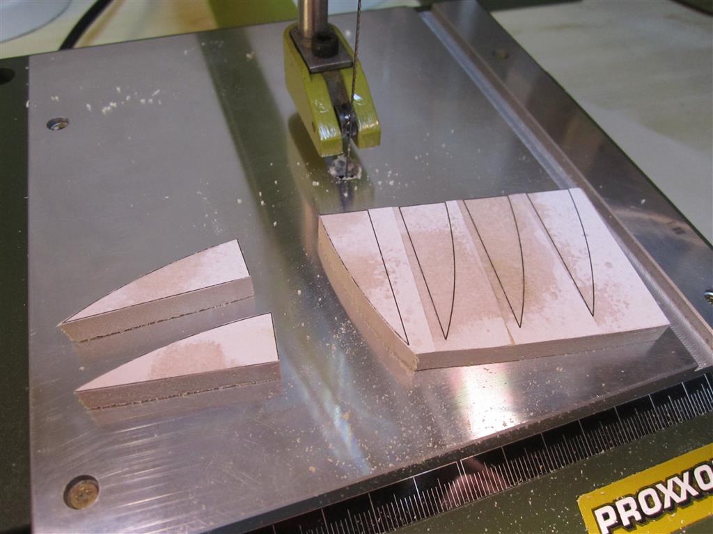
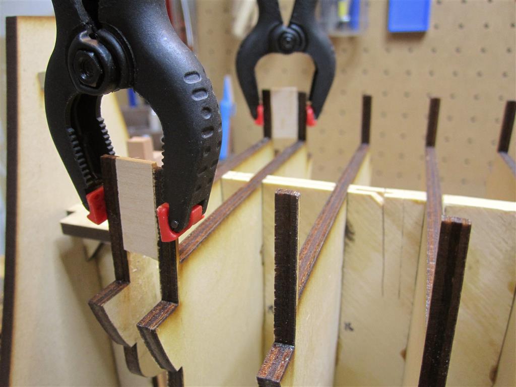
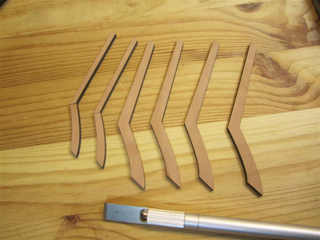
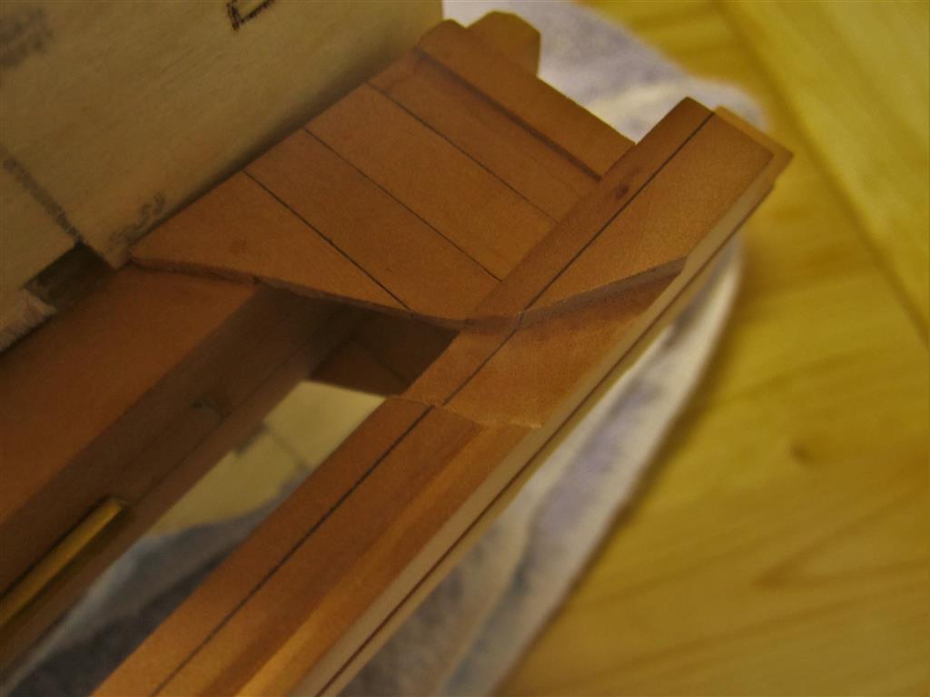
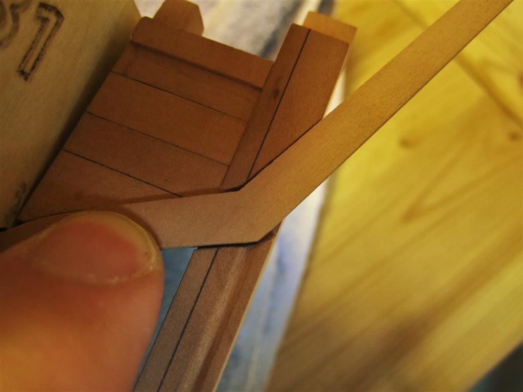
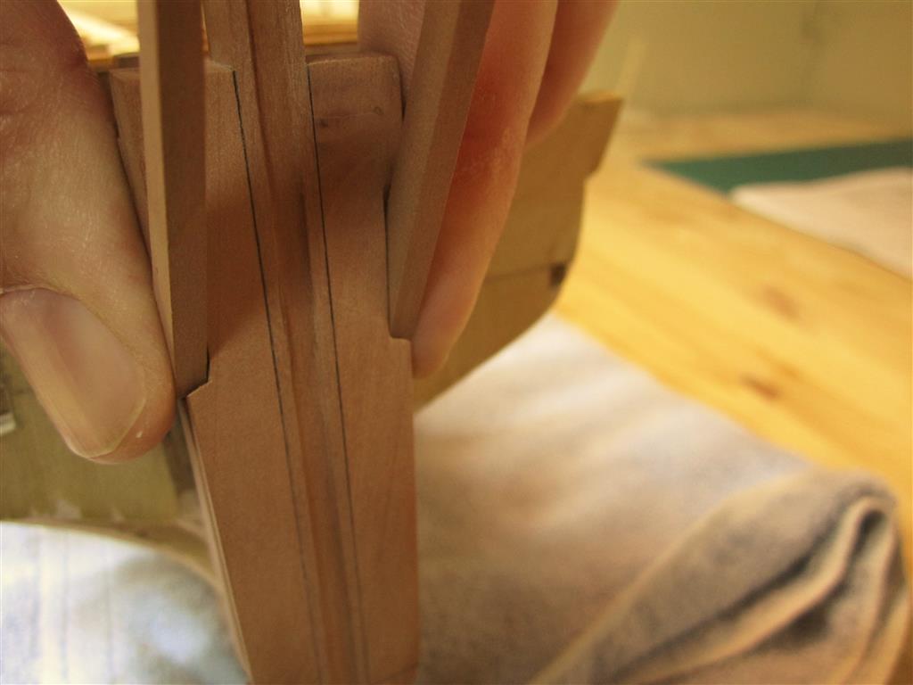
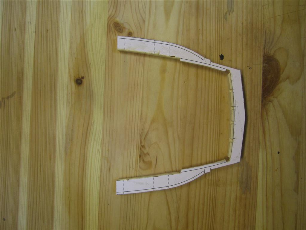
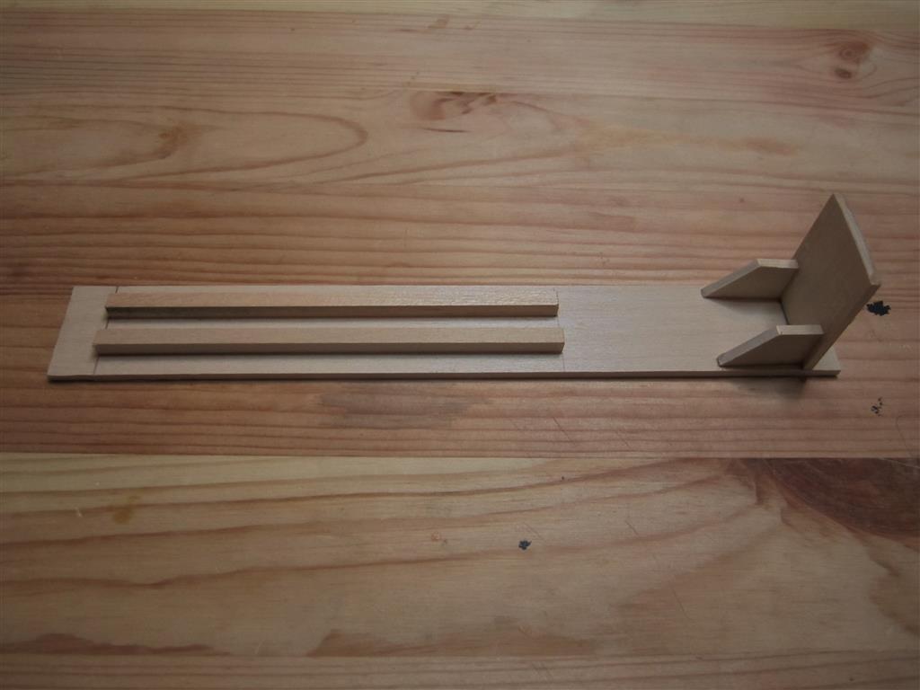
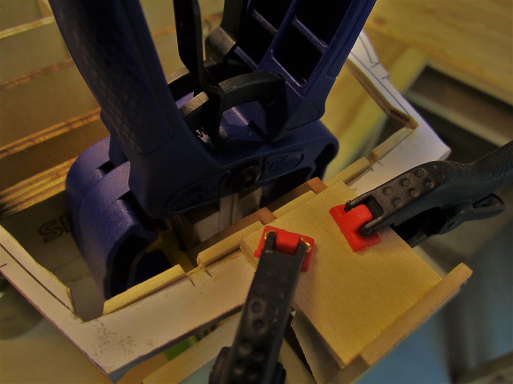
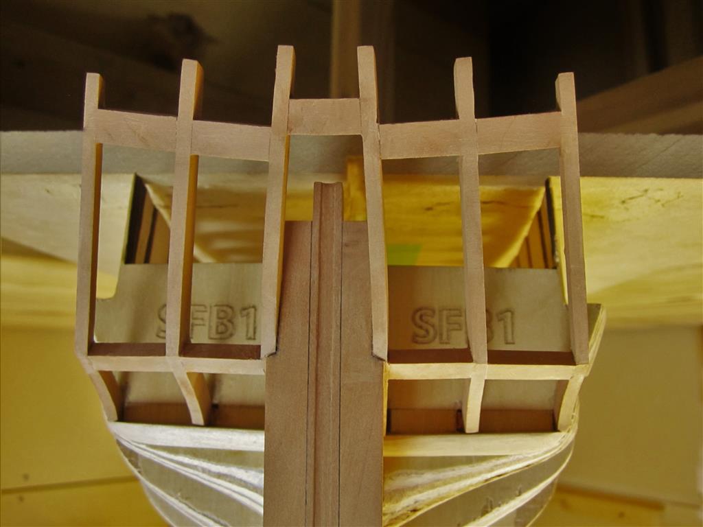
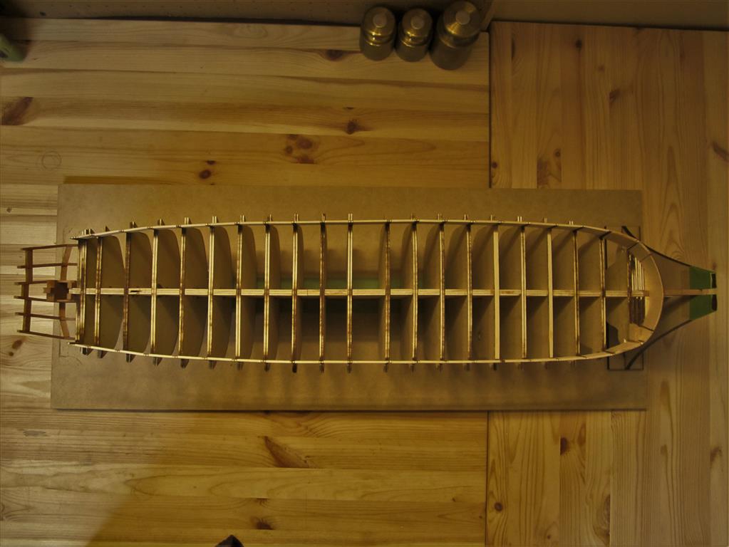
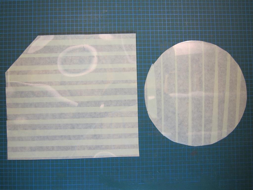
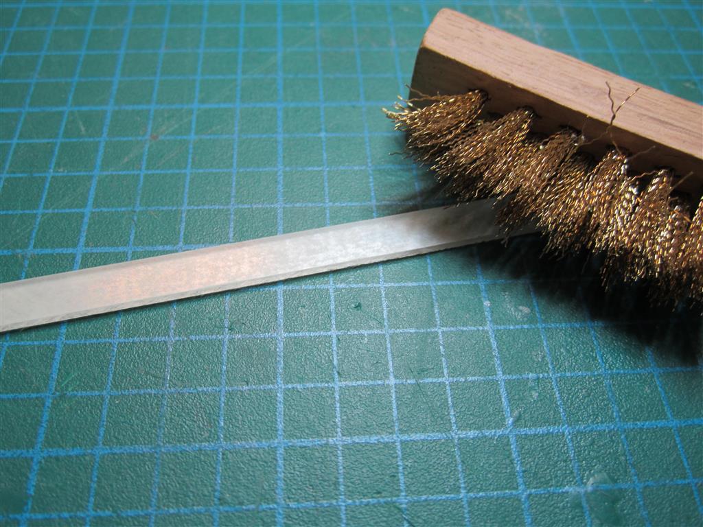
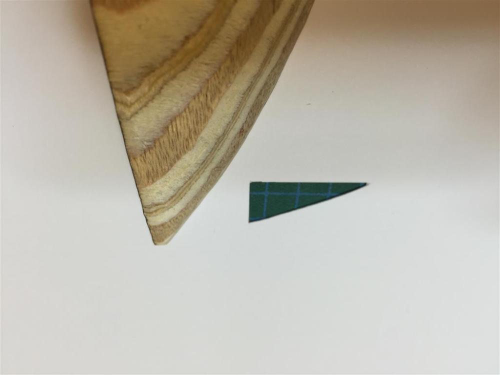
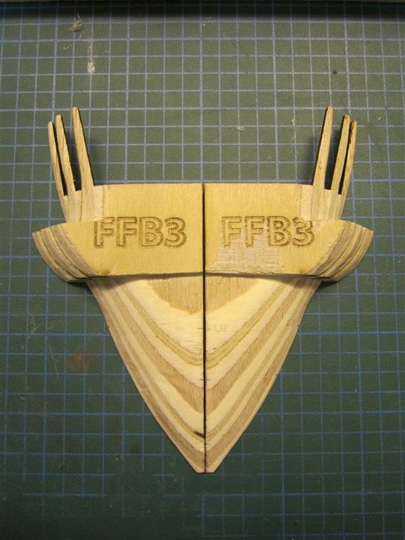
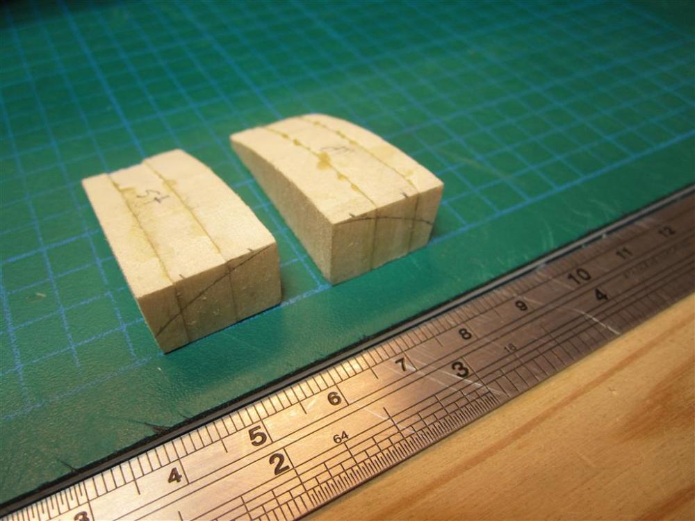
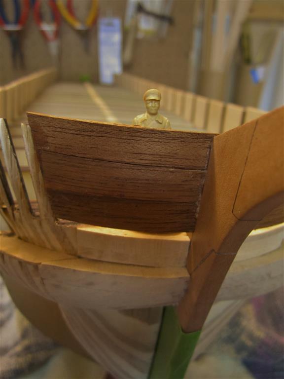
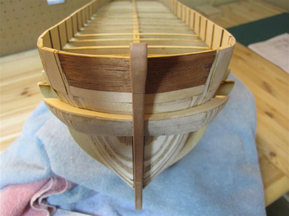
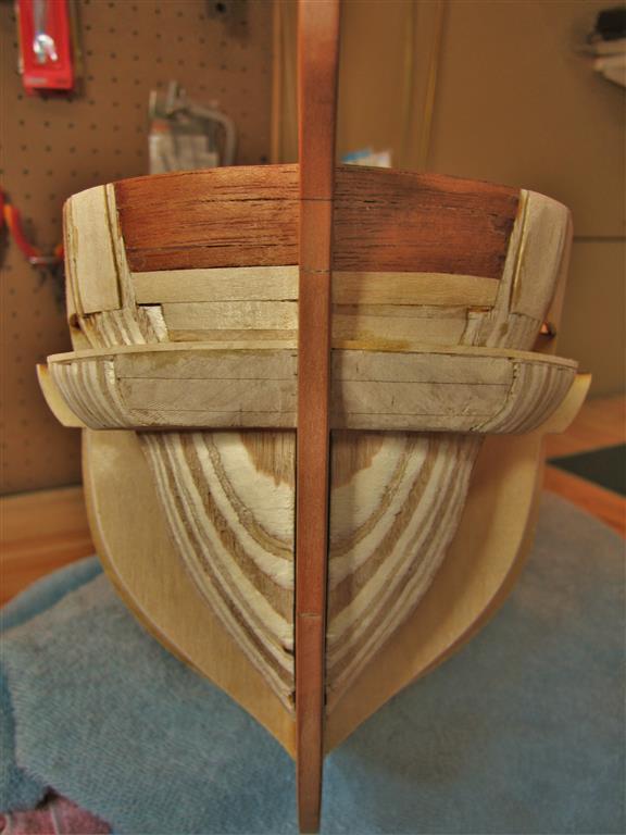
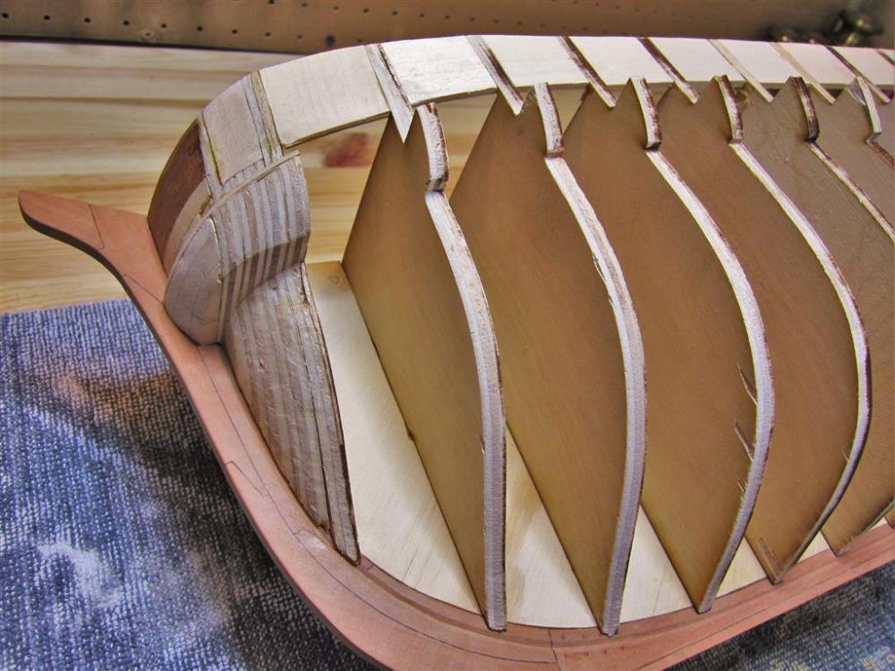
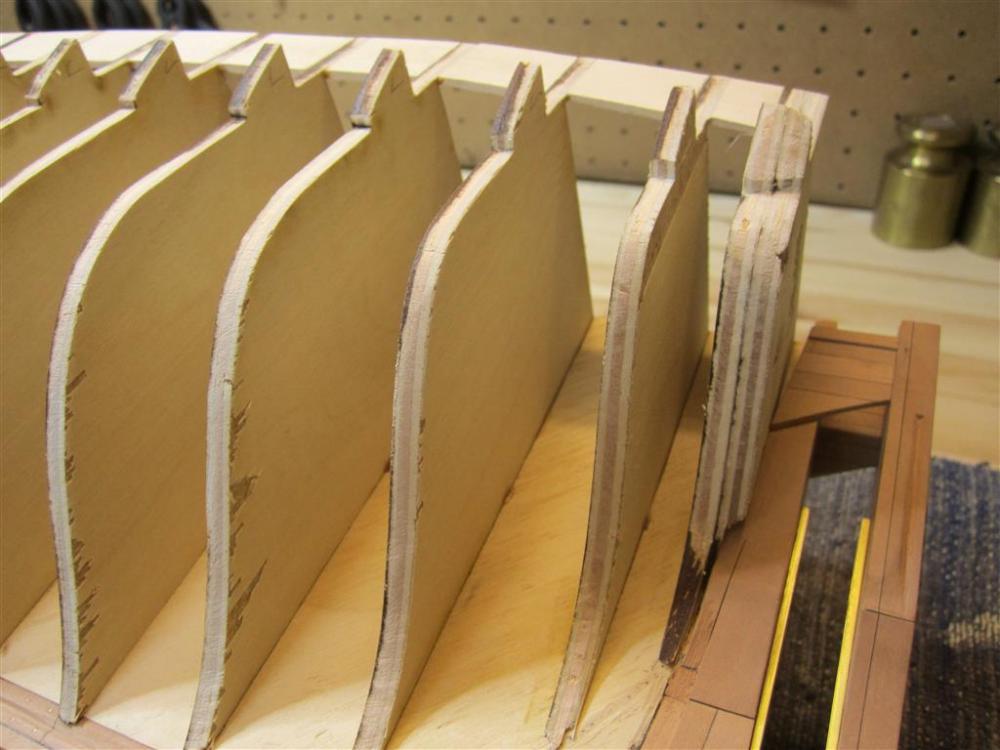
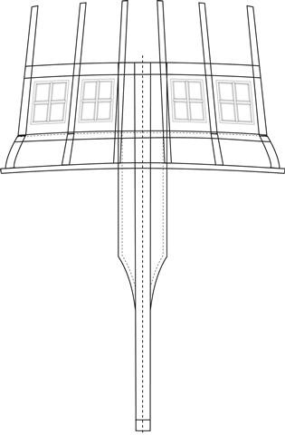
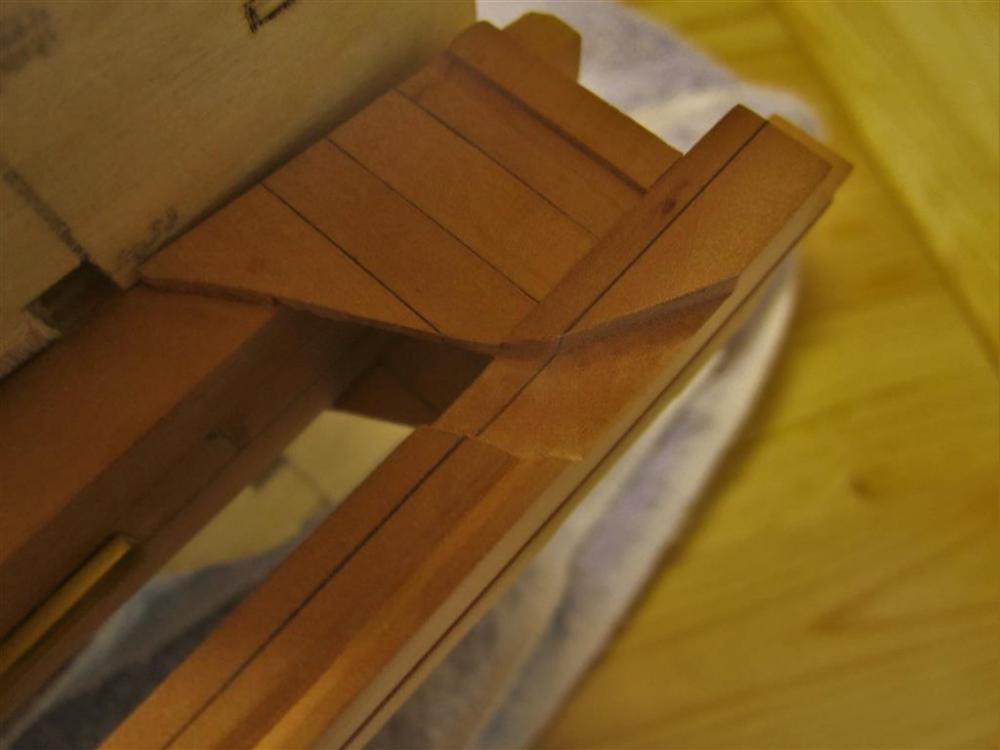
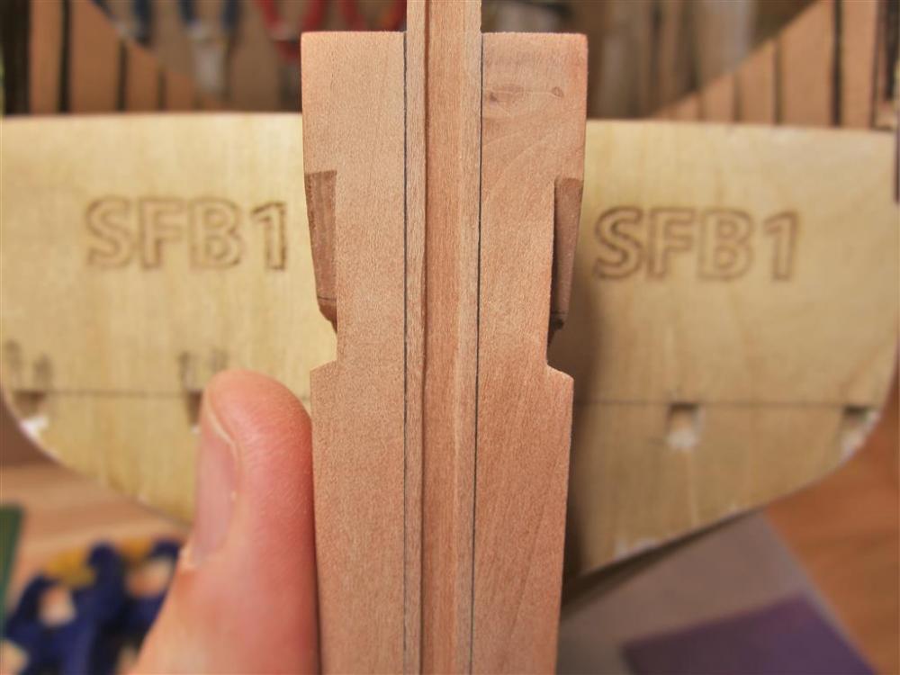
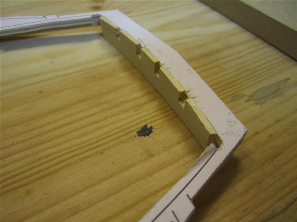
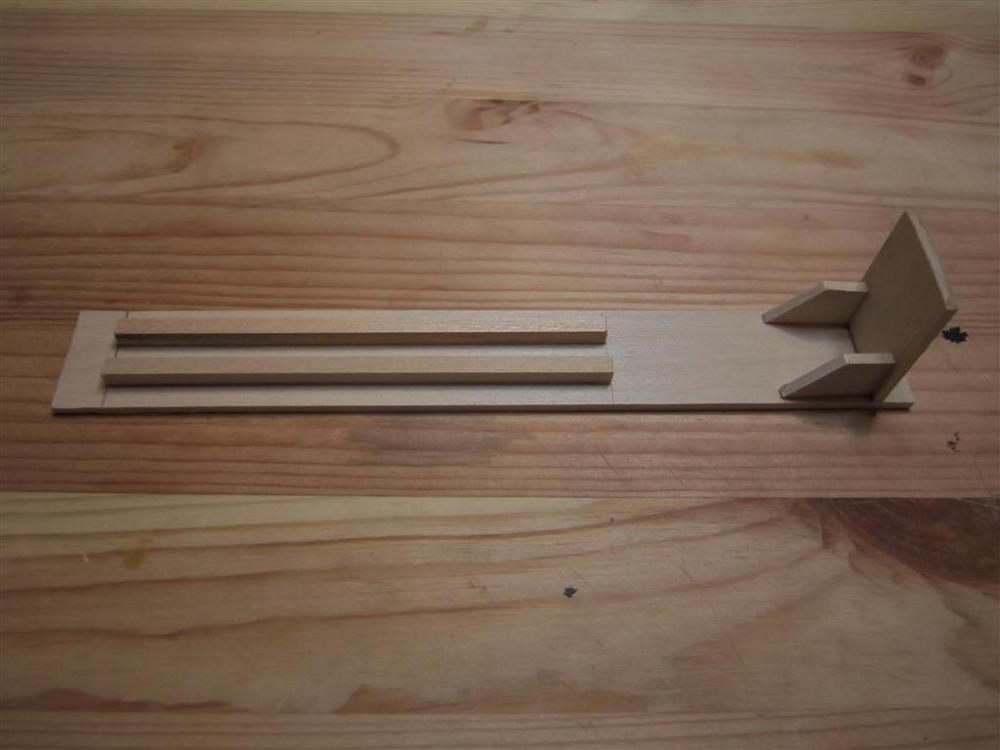
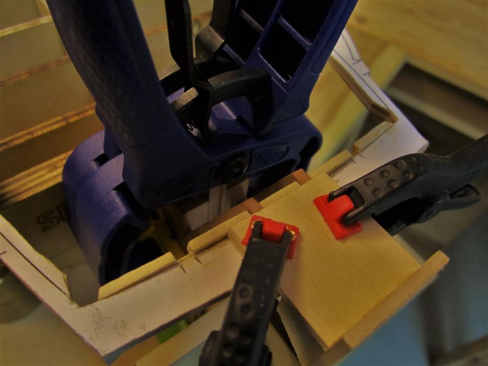
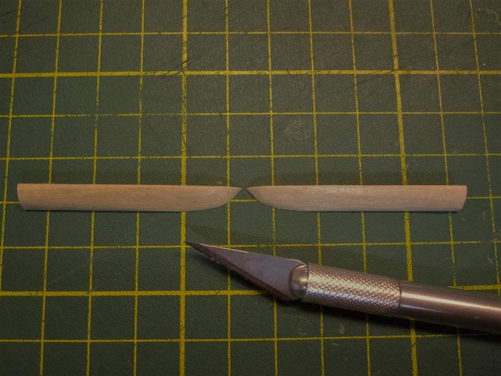
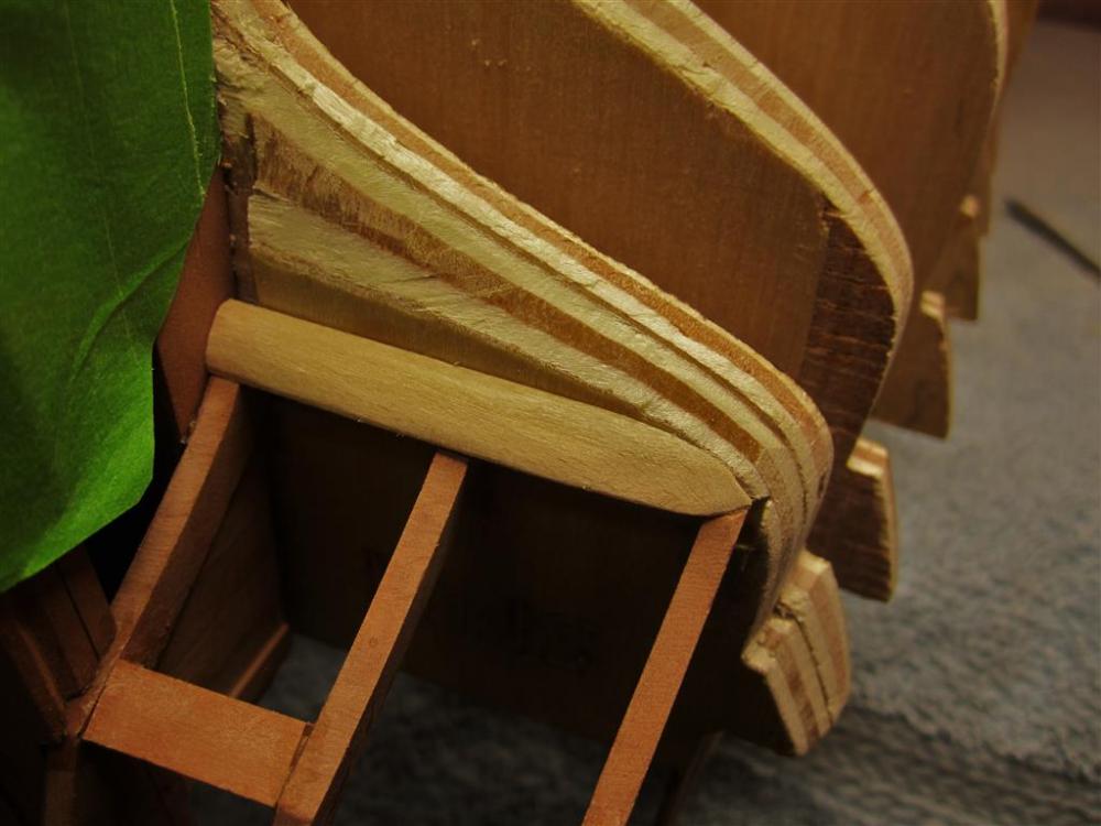
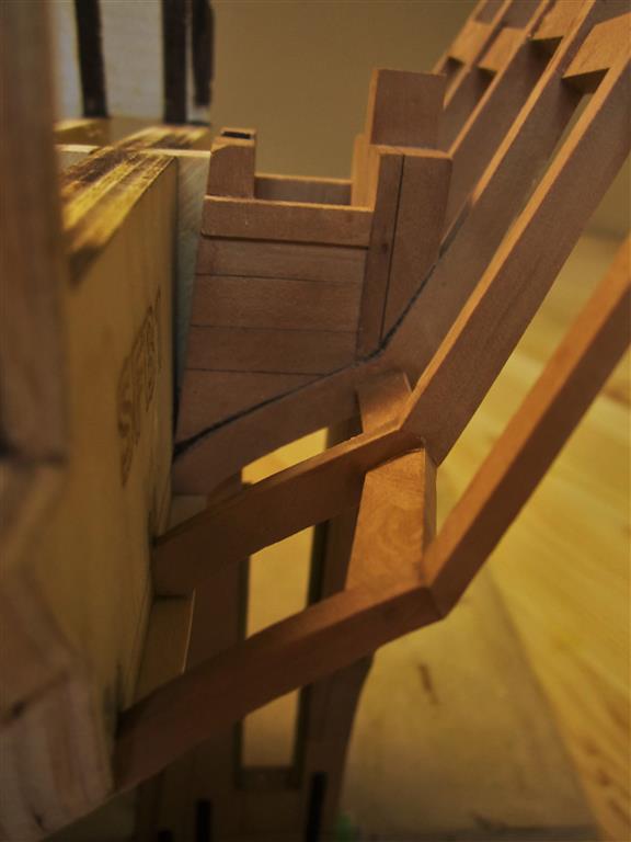
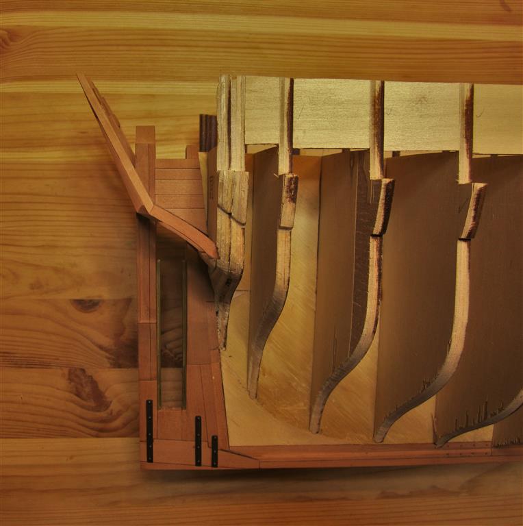
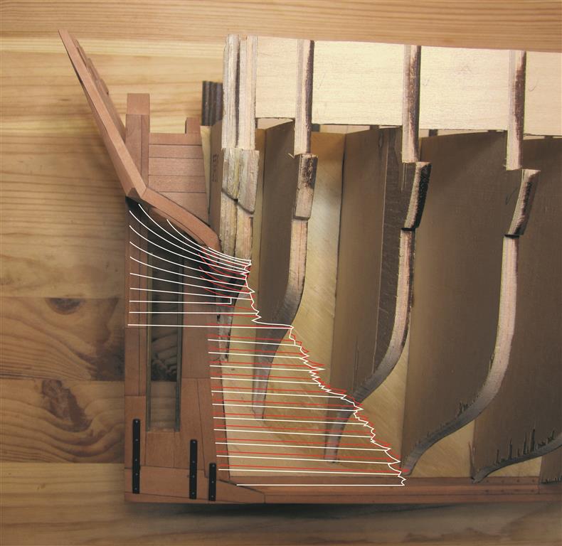
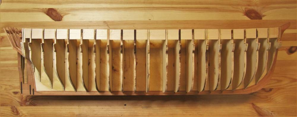
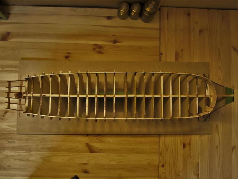
 FAIRING THE HULL I haven't posted in many weeks, but I have been busy working on preparing Terror's hull for planking. I've been relatively obsessive about this aspect of my build, because getting the shape of Terror right has been a real challenge. She was modified so many times (and had so many layers of planking), that her hull shape was somewhat of a mystery to me (at least at the bow and stern). However, I think I've reached a stage where I can move forward. Below I'll present the steps in the process and what I learned about Terror (and Erebus), as I worked. Before I could begin faring the hull, it was necessary to fill in the stern and bow of the model using filling blocks. I created these from 1/4" plywood, laser cut using measurements from the ship's plans. This image displays the three starboard filling blocks used at the bow. The filling blocks were carved to shape using card guides cut to match the lines of the half breadth plan. Placing the filling blocks side-by-side as they were carved ensured that they were symmetrical. The lamination in the plywood was also helpful in this regard. However, plywood is a poor carving material, and I would think twice about using it again. In 1839, the solid chock (ice) channels on Terror were extended around the bow. I constructed these from several layers of basswood. These chocks were then shaped to match the proper cross section of the channels. The ice channels were glued in place on the bow and scrap wood was used to rough out the bulwark shape. The excessive use of glue didn't escape Mini-Crozier's critical eye. The gaps in the bulwarks were filled using basswood strips of appropriate thickness. Rather than filling and sanding seams and gaps, basswood leveling strips were applied to the upper surface of the ice channels. The channels were then filed to shape using card stock templates. Scrap wood was used to fill in any large gaps in the bulwarks. The completed bow just prior to sanding. I checked the symmetry and level of each side of the ice channel obsessively with a height gauge while the model was still on its building board. The asymmetry of the filling stock used to shape the bulwarks is a product of the odds and ends in my spoil bin, and while unsightly, it won't be visible when the model is planked. This image shows the faired forward bulkheads and bow filling blocks, just prior to final sanding. The merchant-like shape of Terror's bow and the imposing nature of the ice channel grafted to it can be seen in this view. Note how far the ice channel overhangs the bow relative to the port side of the ship; this is because it sits on three layers of planking, including a layer of 3" lower planks, a second layer of 8" planks, and a third layer of even thicker reinforcing planks. An image of the faired stern, detailing the single filling block used in this area. The stern rabbet is in the process of being finalized in this image. With the hull faired, the stern timbers could be installed. These were laser cut from Swiss pear. The outermost stern timbers, on the left, were cut in two sections, as they form an angle when installed correctly. Prior to describing how the stern timbers were installed, it is important to note how this area of the ship was designed by Oliver Lang, the shipwright who refit Erebus and Terror for the Franklin Expedition. Because of the massive size of the propeller well and the rudder post which formed its aft wall, Lang had little room left to fit the six stern timbers and four stern lights (windows) in the counter. His solution can be seen in the 1845 Erebus and Terror stern model in the collection of the National Maritime Museum, in Chatham. Inspection of the propeller well in that model shows that the stern timbers were actually used to form side walls of the well. However, they could not be fayed directly to the sides of the rudder post as this wouldn't leave enough space for the stern lights (windows). This meant that the stern timbers had to be inset into the sides of the rudder post by three inches to form the side walls of the propeller well. Remarkably, Lang achieved all of this with almost no modification of Terror's existing stern framing. With the rudder post locked directly into the two central stern timbers, the whole structure was incredibly robust. It is important to note that the inset stern timbers may not have been needed on Erebus, which had a slightly wider counter than Terror. Simplified plan of Terror's counter architecture. Note how the stern timbers overlap the rudder post. Also noteworthy is the position of the upper deck transom, which could be fayed directly to the aft side of the rudder post in this configuration. In this image, the slot/inset for the stern timber has been cut into the rudder post. Note how it is level with the interior sides of the propeller well. A view from the aft side of the rudder post showing the insets for the stern timbers. Note the square slots in the stern filling blocks cut to accept the heels of the stern timbers (no wing transom was required for construction for this stage). Checking the fit with a stern timber. This won't be visible in the finished model. Checking alignment. The stern timbers were fitted with the help of a jig. The jig was designed to be clamped to the bulwarks, using the station lines printed on it as guides. Detail of the aft part of the jig. A height gauge was necessary to ensure that the jig was properly aligned along its aft margin. This gauge slid tightly over the aft support of the building board, using the tracks on the left. The jig and height gauge in place, with the center two stern timbers installed and clamped. "Wing transom" filling pieces. These are not entirely accurate architecturally (they are more like half-transoms), but were carved and sanded to shape to provide a platform for planking the stern. The "wing transom" in place. Note the very slight curve in the transom. As confirmed by the 1845 stern model and the 1839 model of Erebus, Terror's stern was very square indeed. Rough transverse framing was installed to support the stern timbers. This framing is not accurate to plan or scale but rather simply supports the structure and will not be visible when the model is planked. See the above plan for the correct framing. As with the bow, I obsessively relied on a height gauge to ensure the entire structure was level and square. A port side view, detailing the stern architecture. Note how the stern timbers adjoined the propeller well and rudder post. The completed stern. Completing the construction and fairing of the model's stern was a milestone for my project. Not only is the model now ready for planking, finishing this stage of the build revealed a minor mystery surrounding how Lang planked Terror's stern . Lang's 1845 stern refit plan stated that an "....additional part of the wale [was] added to the after end of the ship to form the well or trunk..." for the propeller. Unfortunately, his plan does not reveal if both layers of planking were extended to accomplish this (Terror was double planked against the ice). However, with the construction of this part of the model, his solution became clear to me. If my model is correct, then it shows that the first layer of Terror's hull planking did not need to be modified in any way by Lang. In fact, it could simply be left in place, terminating at the edge of the lower counter, as was typical of bomb vessels. Again, if my model architecture is correct, then it shows that Lang could have just extended the second layer of planking to the rudder post. The 1845 stern model shows that this planking rose straight up the rudder post and, when it hit the counter, turned to trace a graceful arc, running from the upper end of the stern rabbet to the lowest portion of the counter at the sides (these planks were fayed directly to the previously planked counter). Lang's stern plan shows that the second layer abutted a beveled margin plank on the counter, although this isn't detailed on his stern model. My planking plan for Terror's stern. The red lines show the lower planking, while the white lines show the upper level of planking. The overlap of the planks accords well with the 1839 midships section for Erebus and Terror. The current condition of Terror. She's just about ready for planking. A view from the upper deck.
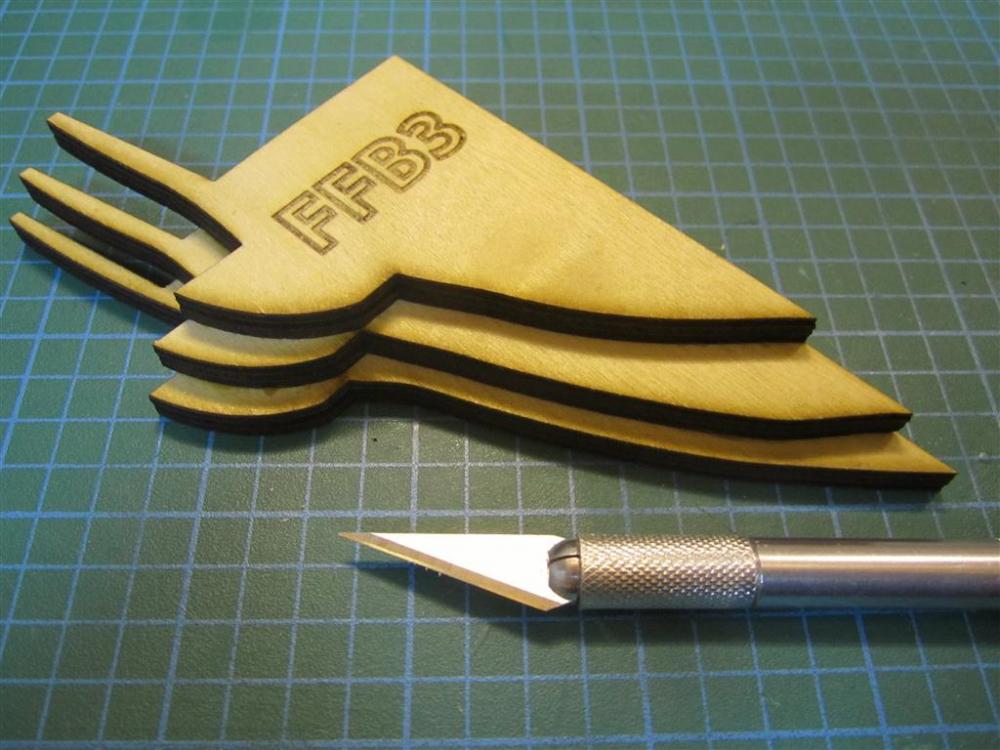


- 346 replies
-
- 22
-

-
- terror
- polar exploration
- (and 2 more)
-
That is something else! Thanks for sharing, and I hope she finds a worthy home.
- 641 replies
-
- 2
-
-
- greenwich hospital
- barge
- (and 1 more)
-
A stunning result. Thank you for sharing and teaching us all along the way. Truly inspiring,
- 641 replies
-
- 4
-
-
- greenwich hospital
- barge
- (and 1 more)
-
A fine choice, Druxey. I really like the look of the sweeps overhanging the base. Will they rest on the surface supporting the model, or will they be free-floating?
- 641 replies
-
- 2
-
-
- greenwich hospital
- barge
- (and 1 more)
-
Thanks everyone for the likes and comments! I hope to have more consistent updates in the future, now that I'm back at it.
- 346 replies
-
- 1
-
-
- terror
- polar exploration
- (and 2 more)
-
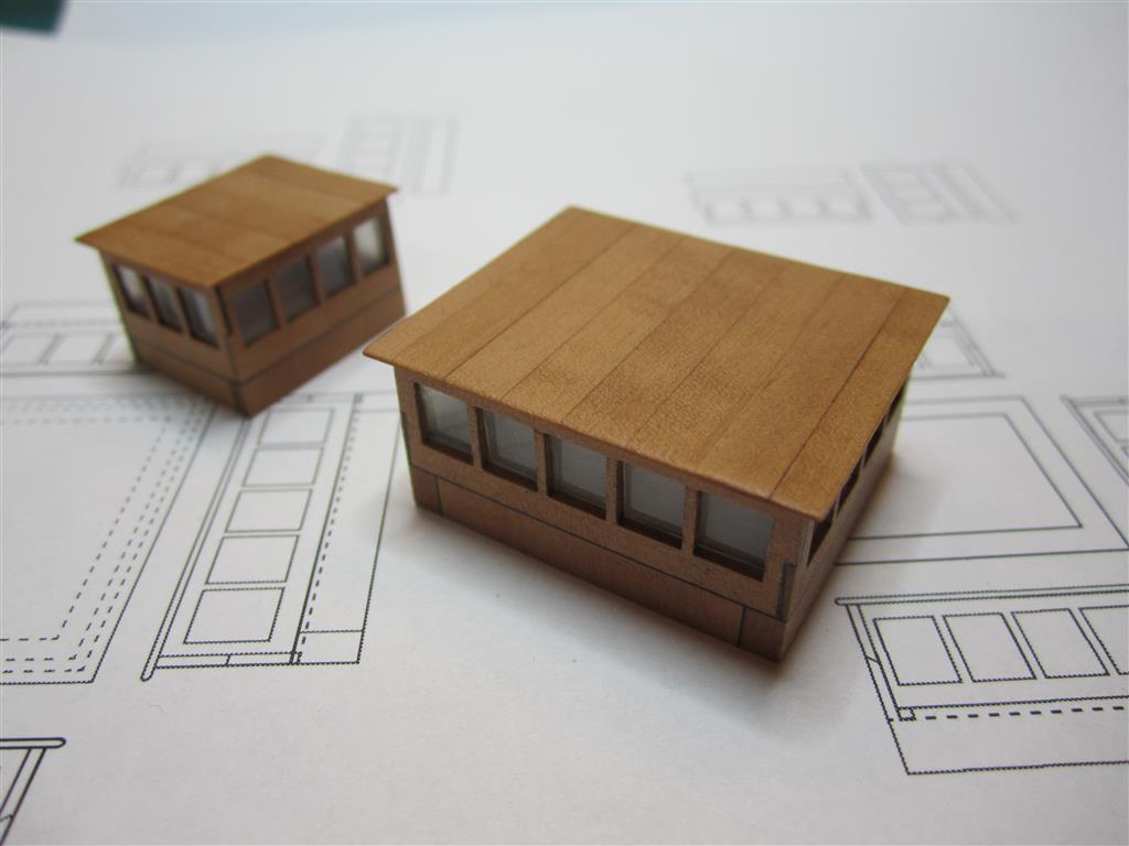
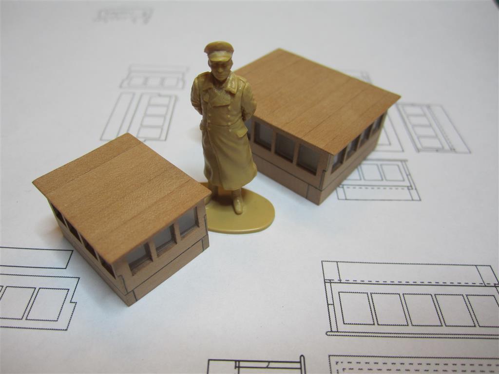
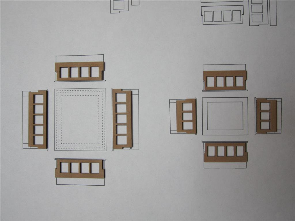
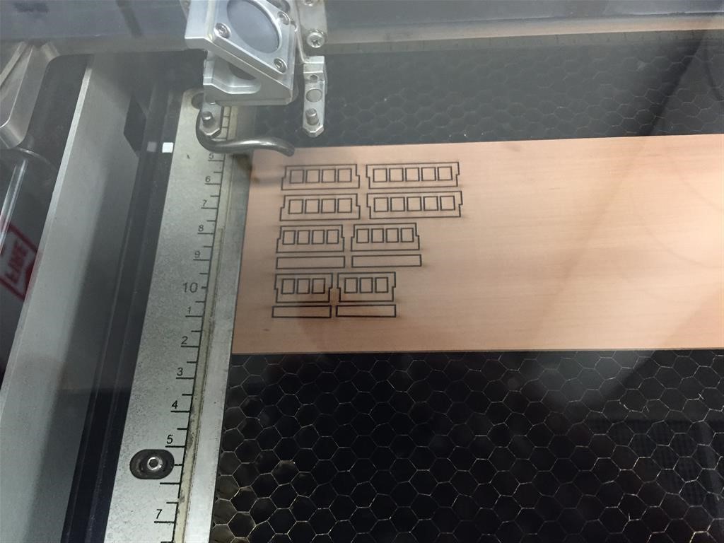
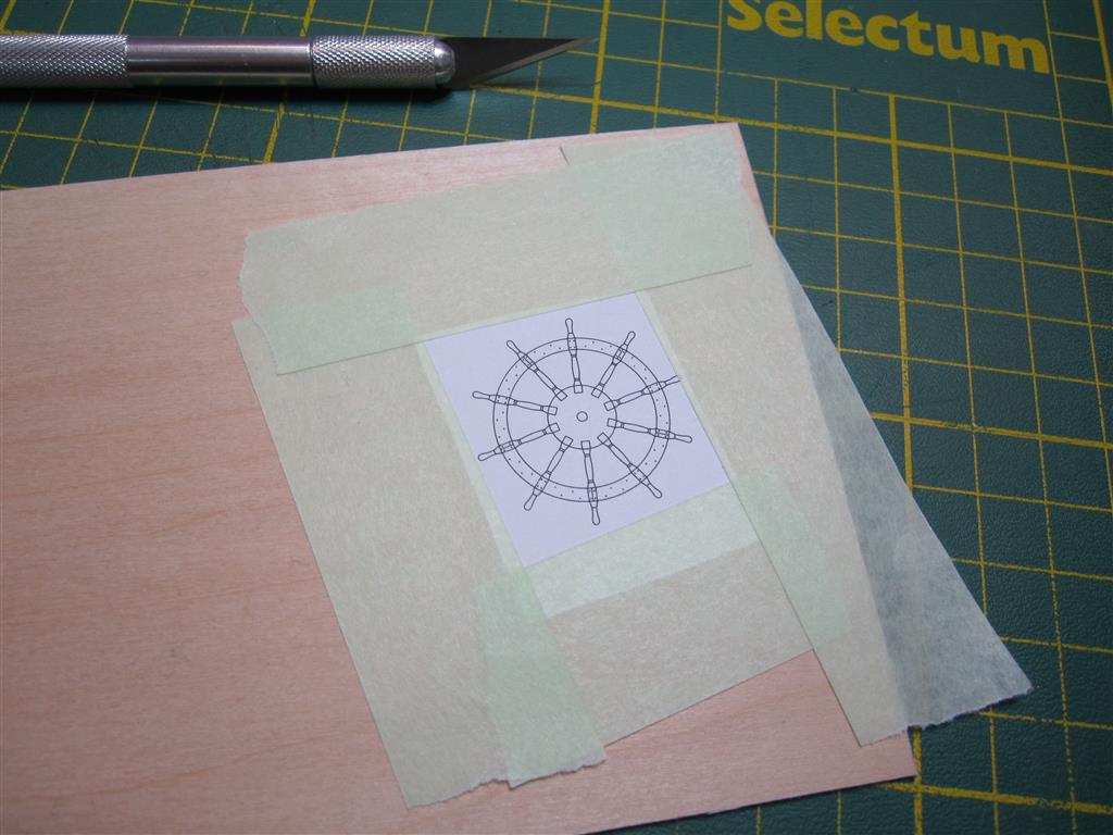
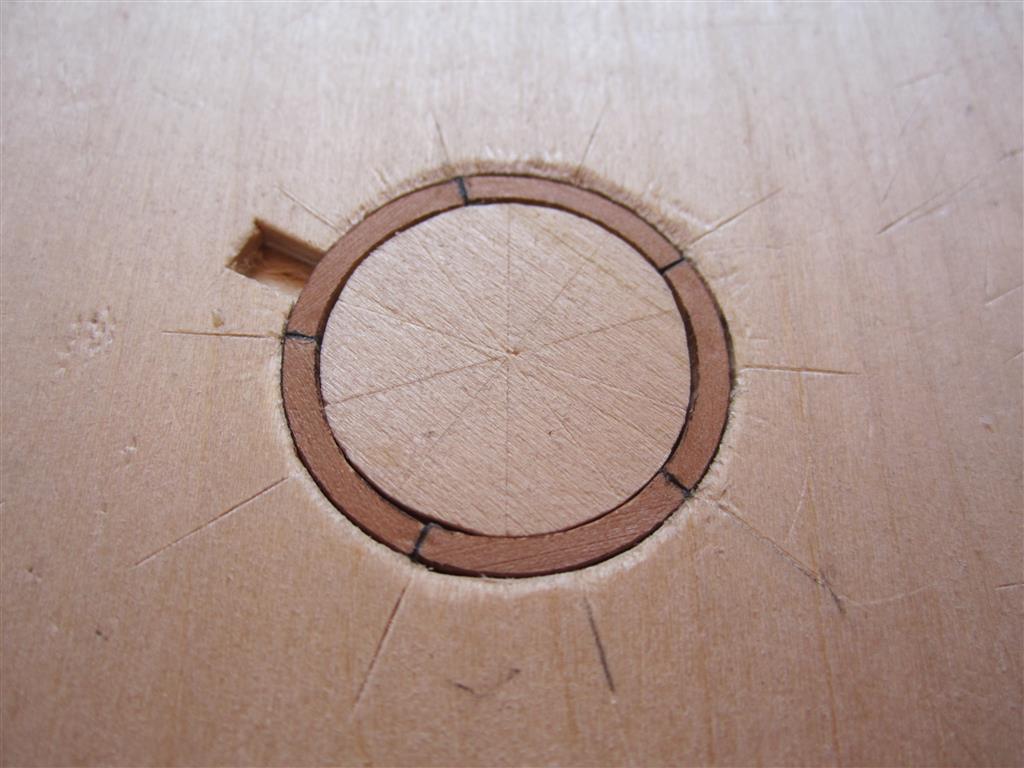
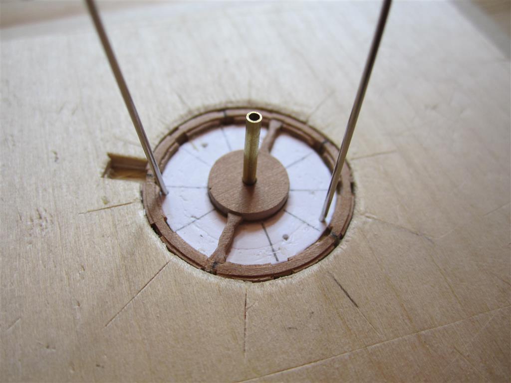
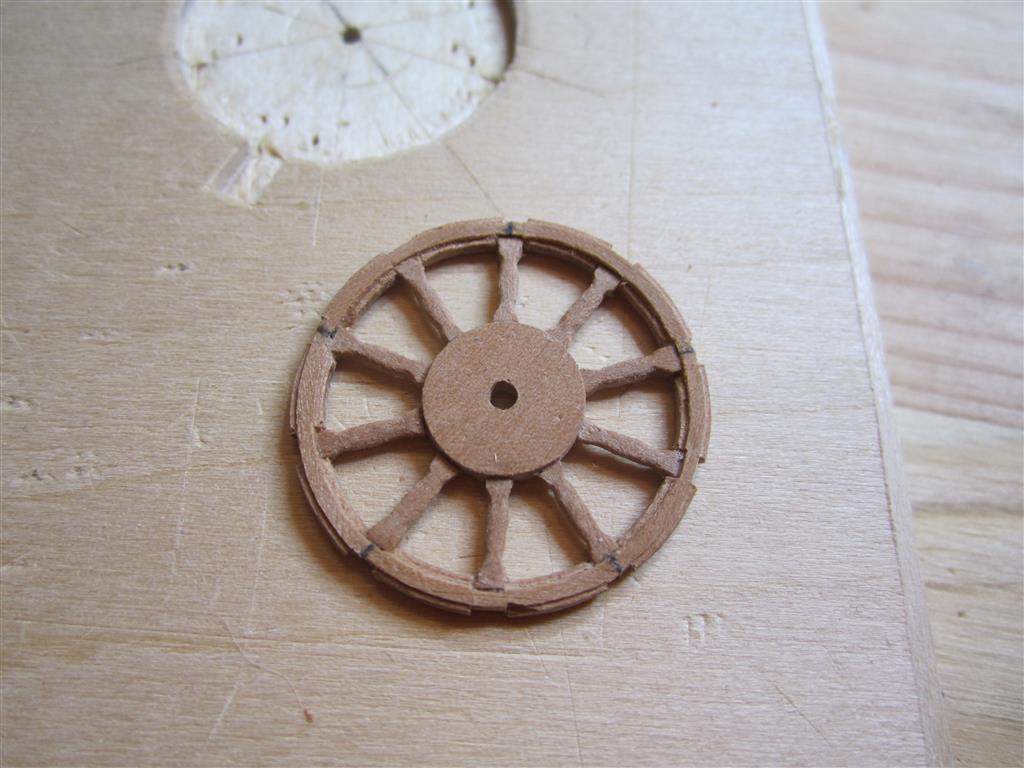
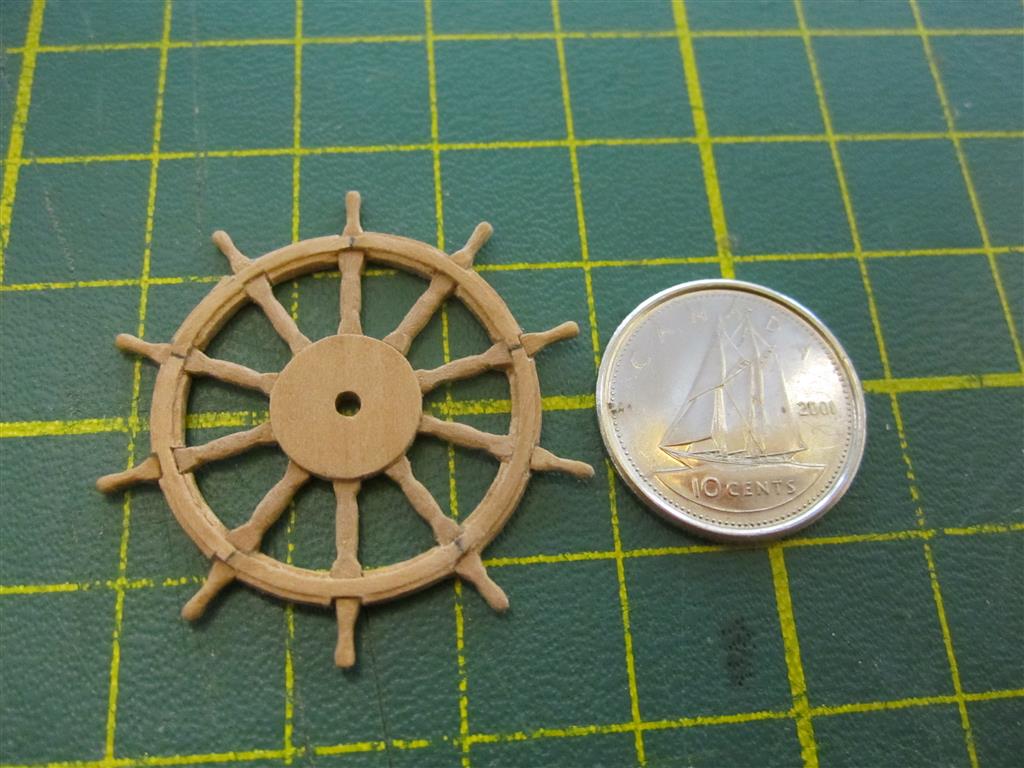
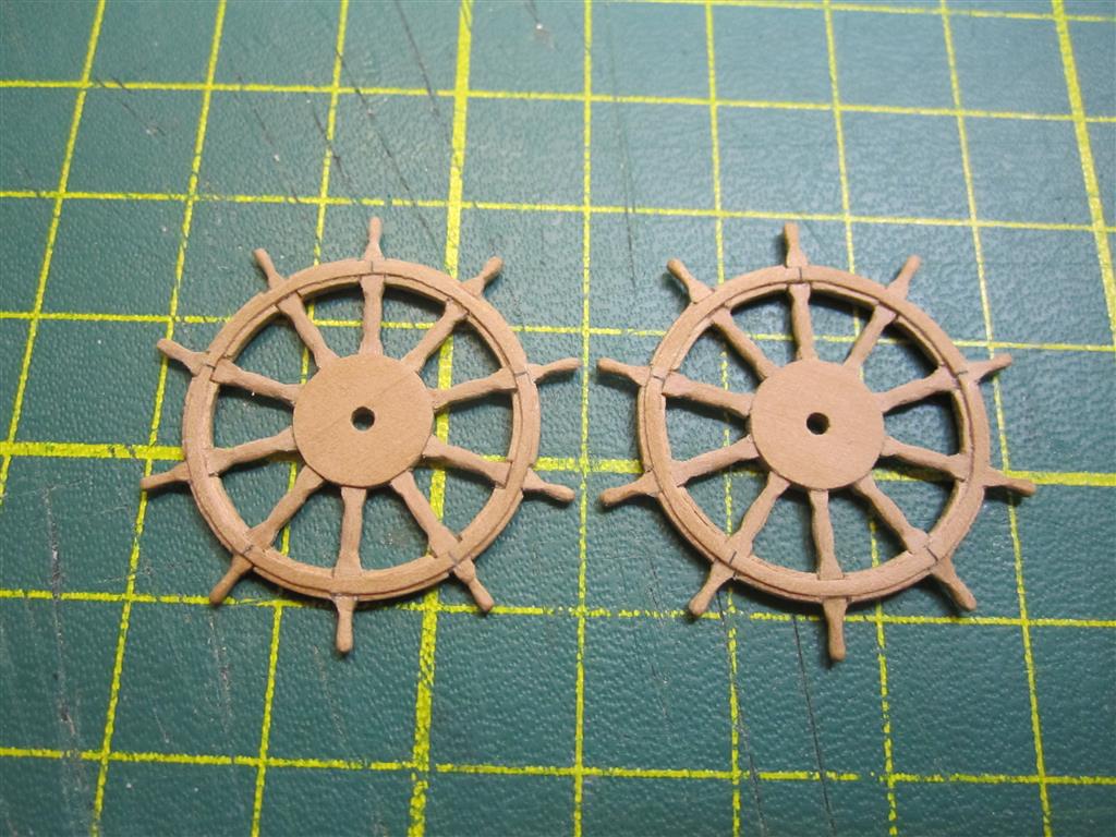
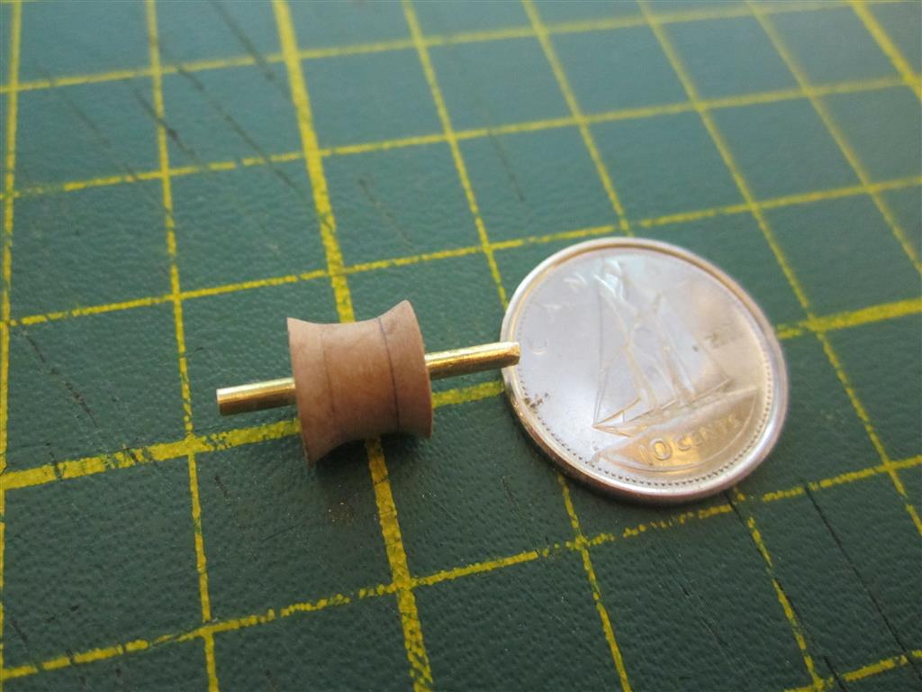
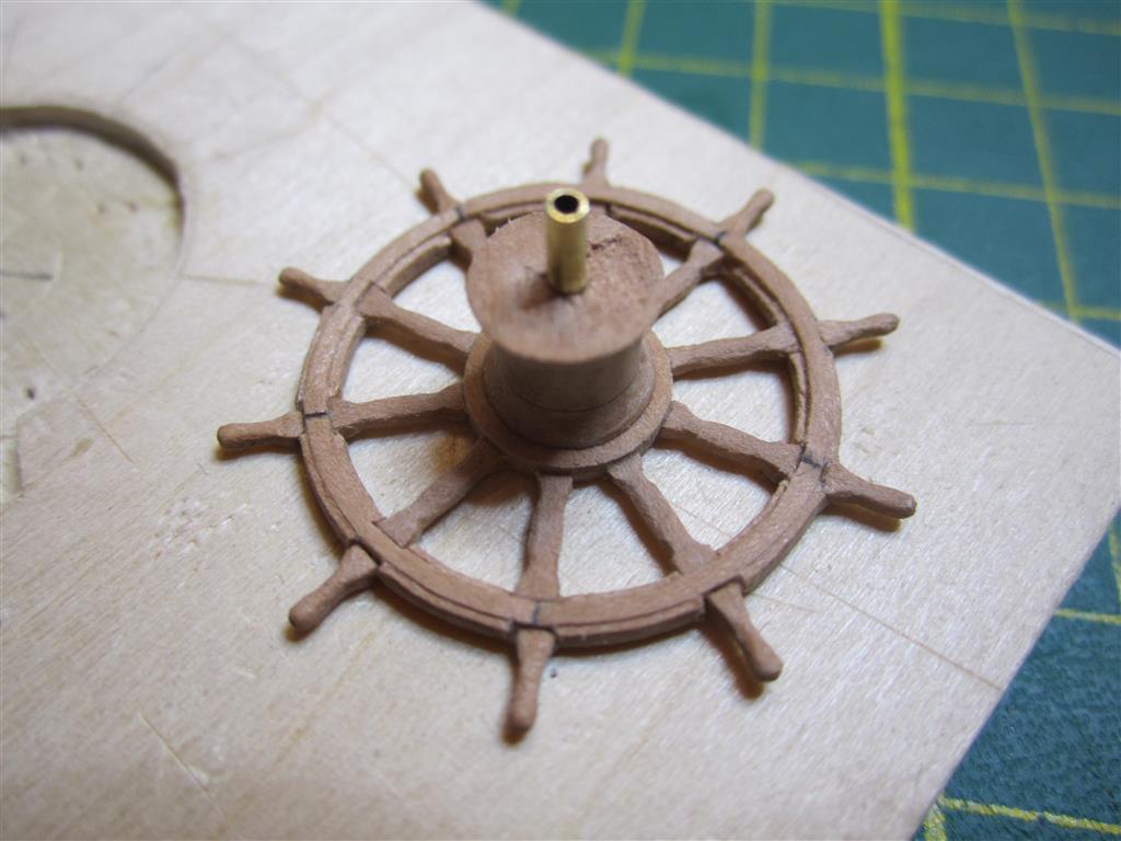
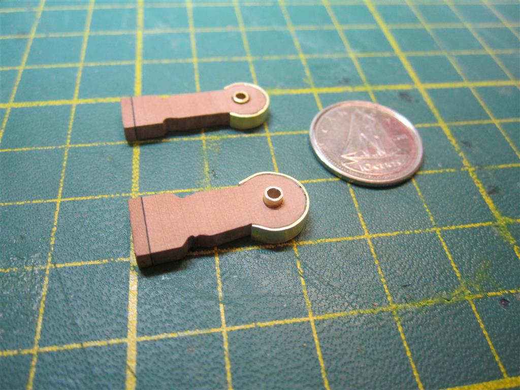
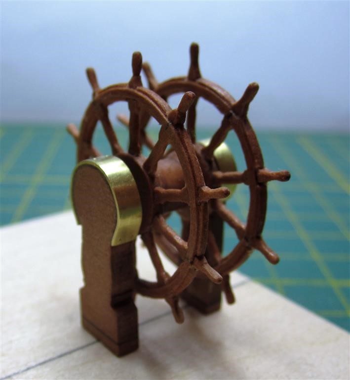
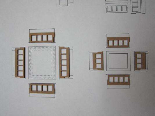
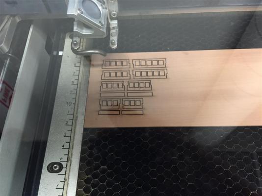
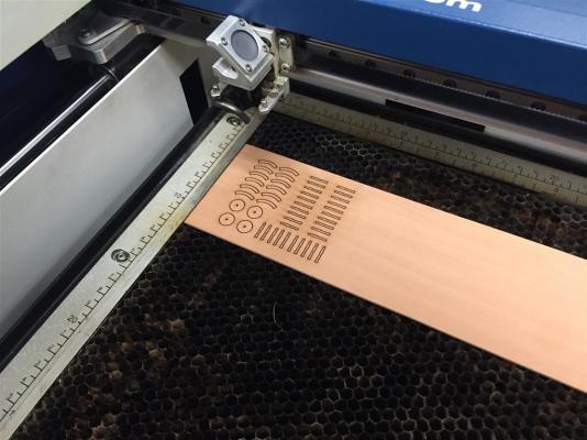
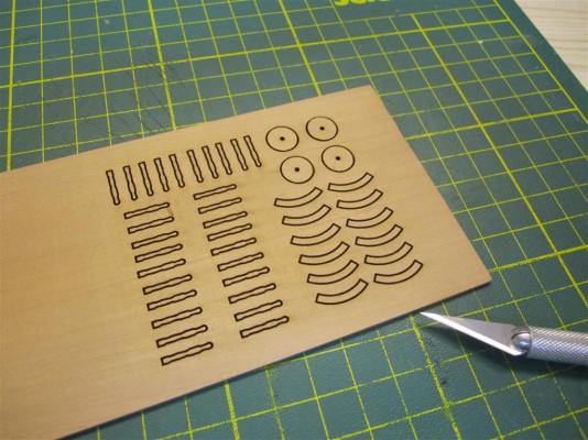
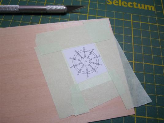
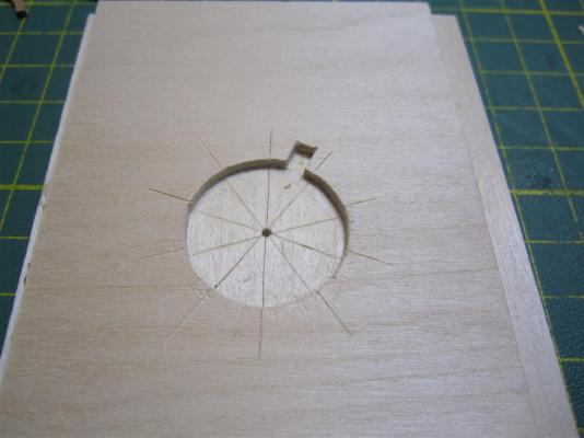
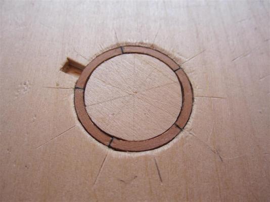
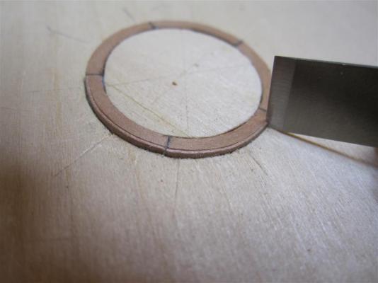
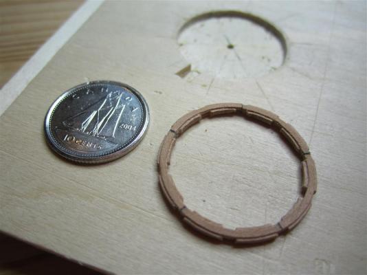
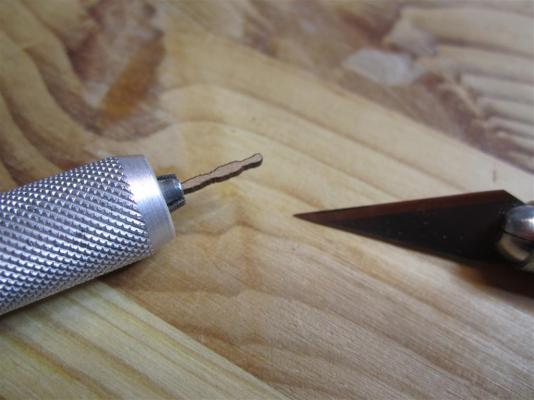
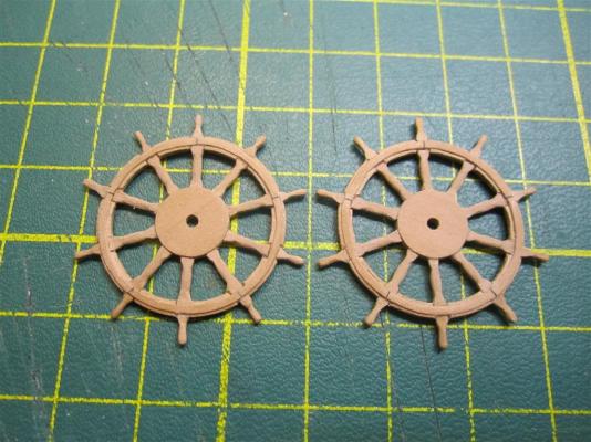
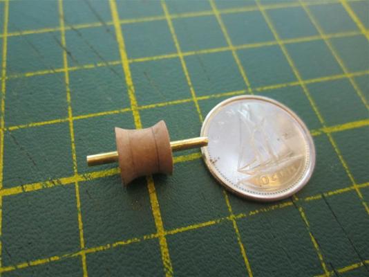
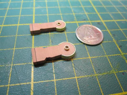
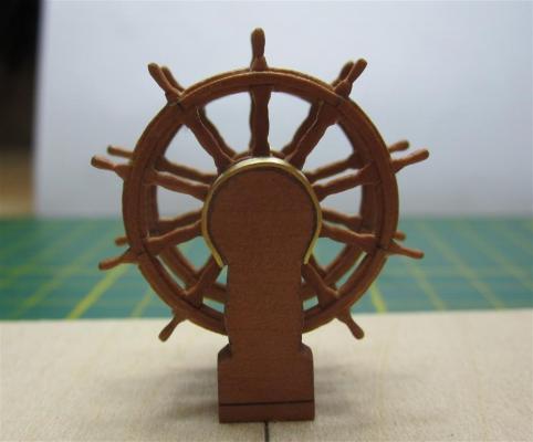
Skylights and Ship's Wheel I've been on a several month hiatus from model building, during which progress has been rather slow. However, over the last few weeks, I have been able to get back to my project. Here are the latest results.... The Skylights HMS Erebus and Terror each had two skylights located on the aft of the upper deck. Both follow a design originally adopted by HMS Terror in 1836. The sides of the skylights were rimmed with panes of glass to allow sunlight into the captain’s cabin and officer’s mess. Unusually, their tops had no peak or even a slight camber – attributes confirmed by the daguerreotype and the NMM model of Erebus. Interestingly, the daguerreotype indicates that the panes were not protected by brass rods as was standard on many Royal Navy vessels of the era – an indication of the peaceful aims of the expedition. In addition, the aft skylight on HMS Trincomalee, which is very similar to those used on HMS Erebus and Terror, provided important details for my recreation. The 1836/1837 and 1839 plans for Terror/Erebus indicate the skylights may have had collapsible sides, at least on the starboard. This would have permitted ventilation, if necessary, though the plans seem to indicate the ultimate aim was to enable the skylights to be used as makeshift companionways. In this scenario, it is likely the roofs of the skylights would have been removable. I opted not to model these aspects of the skylights, as I had no information on how these features were designed. Laser cutting the wheel components. Comparing the parts to the plans. Preparing the plastic stock for the windows. I use electronic blister packaging for this. It is crystal clear, quite thin, does not discolour in the sun, and is easy to work. The window panes were inlaid as one strip. I scoured and sanded the interior to simulate window frost (and to obscure the inside of the POB ship). The completed skylights. Mini-Crozier stands next to the his skylights. The Ship’s Wheel The 1836/1837 and 1839 plans of HMS Terror and Erebus show that their wheels were slightly smaller than those typically used on Royal Navy ships, being more consistent with those used on merchant vessels of similar size. The recently recovered portion of Erebus’ wheel, as well as the Le Vesconte daguerreotype, reveal that the wheel itself was relatively plain and was held together by copper alloy screws or nails. Fine examples of this type of wheel can be found today on HMS Unicorn and HMS Trincomalee. Trincomalee’s wheel isperhaps closest in design, with distinctive grooved felloes nearly identical to those on the HMS Erebus wheel found by Parks Canada. Like most large Royal Navy vessels, Erebus and Terror’s wheels had ten spokes, each radiating at 36 degrees from the barrel. Usually, survey vessels ships of this size would have had an eight spoke wheel; the extra spokes would have substantially increased the strength of such a small wheel, and perhaps it was deemed necessary for arctic exploration. The Le Vesconte daguerreotype indicates that the top of the wheel pedestals were protected by a very heavy moulded brass guard plate. This can be confirmed by the subtle reflections seen on the plate in the daguerreotype. HMS Trincomalee has similar heavy copper guard plates on its wheel pedestals. Laser cutting the wheel components. Th finished sheet. I used the wheel plan to assemble a building jig. The completed jig. Gluing the felloes. Creating the outer groove in the felloes. The same procedure was used for the inner groove. The rim was notched to receive the spokes. I don't own a lathe, so each spoke was laser cut from sheet stock, then filed into final shape. Assembling the wheel. The card stock allows for the spokes to be centered on the rim. Spokes in position. The completed wheel with a 10 cent piece for scale. The second wheel compared to the first. The barrel was made from three pieces of sheet stock, and filed to final shape. Gluing the barrel to a wheel, using the spindle as a guide. Note the damage on the barrel - caused by a dull blade. The completed pedestals, with the brass guards in place. Limited information on the pedestal hubs was available, so here they are made as simple brass tubes. They are barely visible in the completed assembly. The completed ship's wheel, after applying a coat of Minwax poly. As always, for more content, please see my blog, Building HMS Terror.


- 346 replies
-
- 28
-
-
- terror
- polar exploration
- (and 2 more)
-
I love how clean and crisp your build is, Chuck. It's like a plan come directly to life (the truest aspiration of any ship modeler?).
- 1,051 replies
-
- 5
-
-
- cheerful
- Syren Ship Model Company
- (and 1 more)
-
I can't express fully how much I admire your work on this. At such a small scale too! Magnificent.
- 641 replies
-
- 7
-
-
- greenwich hospital
- barge
- (and 1 more)
-
How could I possibly have missed this? I'm very excited to follow your log, Druxey. A fascinating subject, too. My notebook and pencil are ready!
- 641 replies
-
- 2
-
-
- greenwich hospital
- barge
- (and 1 more)
-
Stunning metal work, Ed, and thanks for the explanation of your blacking techniques. I admit I'm just a little encouraged to hear an artist like you has troubles occasionally - as blacking metal often seems more like alchemy to me than chemistry.
- 3,618 replies
-
- 6
-
-
- young america
- clipper
- (and 1 more)
-
Excellent work. What solder/paste did you use? It seems to blacken well.
- 3,618 replies
-
- 2
-
-
- young america
- clipper
- (and 1 more)
-
What a gorgeous bit of work that is. I am inspired to greater achievement every time I visit your log.
- 3,618 replies
-
- 8
-
-
- young america
- clipper
- (and 1 more)
-
A beautiful gesture. He clearly loved it. Thanks for sharing your wonderful project.
- 209 replies
-
- 9
-
-
- cheerful
- Syren Ship Model Company
- (and 1 more)
-
I feel guilty that I'm learning so much from your free tutorials (here and on your website)! Excellent work!
- 1,051 replies
-
- 7
-
-
- cheerful
- Syren Ship Model Company
- (and 1 more)
-
I wish I could build half as quickly as you, Ed! Beautiful work. Learning lots from following along.
- 191 replies
-
- 5
-
-
- young america
- clipper
- (and 1 more)
-
Stunning, clean work!
-
Thanks very much for the comment! I really appreciate it. I think many would prefer that I were building Erebus, but I still contend that Terror is the more interesting vessel. Not only did she have more adventures in polar regions than Erebus, she was actually used in battle. In fact, every time we see a baseball game, Terror gets serenaded before the match. Some of the "bombs bursting in air" were actually lobbed by Terror. From another vantage, if Terror remains "lost", no one can prove that I got anything wrong in my reconstructions! )
- 346 replies
-
- 6
-
-
- terror
- polar exploration
- (and 2 more)