HOLIDAY DONATION DRIVE - SUPPORT MSW - DO YOUR PART TO KEEP THIS GREAT FORUM GOING! (Only 13 donations so far - C'mon guys!)
×

Erebus and Terror
-
Posts
410 -
Joined
-
Last visited
Content Type
Profiles
Forums
Gallery
Events
Everything posted by Erebus and Terror
-

THE BLACKEN-IT TRIALS
Erebus and Terror replied to Erebus and Terror's topic in Metal Work, Soldering and Metal Fittings
Hello Druxey, This is very good advice. In fact, very thorough mechanical preparation of the surface would likely remove the need to use muriatic acid. I admit my steps are in some respects redundant; each stage cleans up anything missed from the previous step. Are these the discs you are using? http://www.woodworkscraftsupplies.co.uk/index.php?cPath=94_101_147 I also wonder if these little discs might work for the smallest pieces? http://www.thepolishingshop.co.uk/acatalog/Dremel_Wheels.html Even after using these, I would probably still use an acetone bath to remove any oils or grease. -
THE BLACKEN-IT TRIALS
Erebus and Terror replied to Erebus and Terror's topic in Metal Work, Soldering and Metal Fittings
Hi Wq. Thanks for the comment. I certainly take your point. It's a matter of preference, certainly. From my perspective the blackening results in a more realistic look in comparison to paint. In short, it looks like black metal, rather than metal painted black. A thin matte coating doesn't distract from this (at least in my eyes) and is barely noticeable after drying. I'd protect painted metal this way as well. To each his own, however. I've seen some superb work using painted metal, and I'm certainly not disparaging it. -
THE BLACKEN-IT TRIALS
Erebus and Terror replied to Erebus and Terror's topic in Metal Work, Soldering and Metal Fittings
Thank you everyone for the great comments; they are really appreciated. Jud and Chuck, your point about the acetone is well taken. All of this sequential preparation is probably overkill, but from what I've learned it is useful for achieving consistent results, especially when coated brass stock is used. Apparently the acetone is often employed as a backup-step to remove any hand oils or dirt that might have crept in after the acid bath. However, it will also remove any lacquers or finishes that muriatic acid will not. This is especially important if you don't adequately sand all portions of the metal prior to the chemical treatments. -
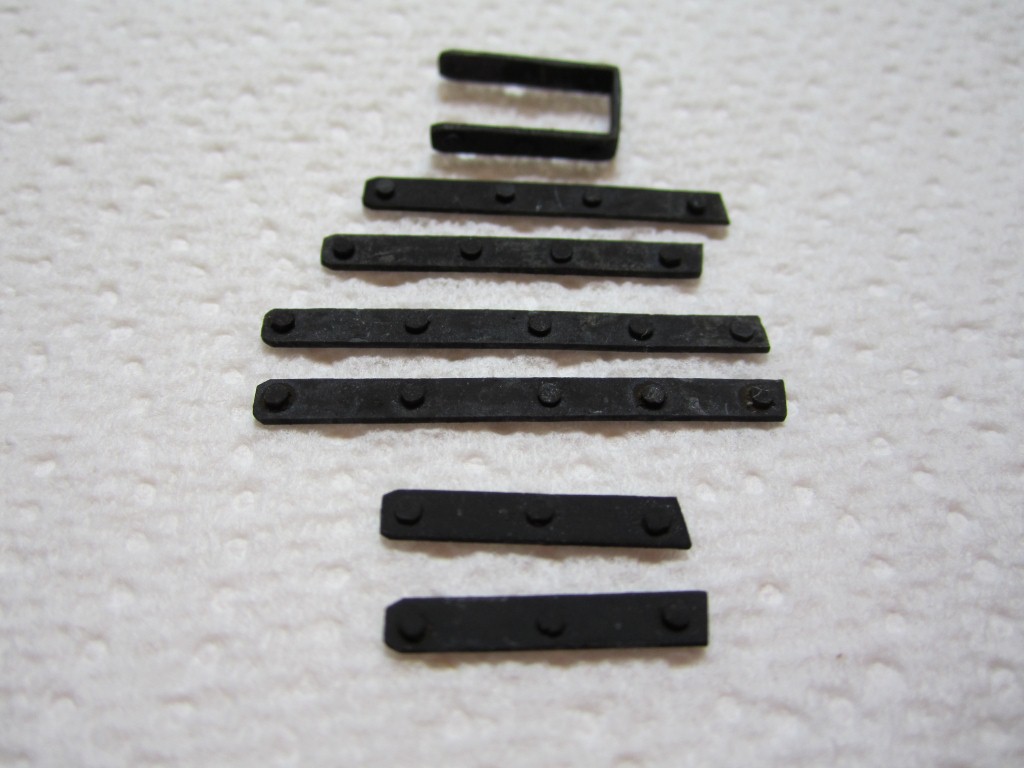
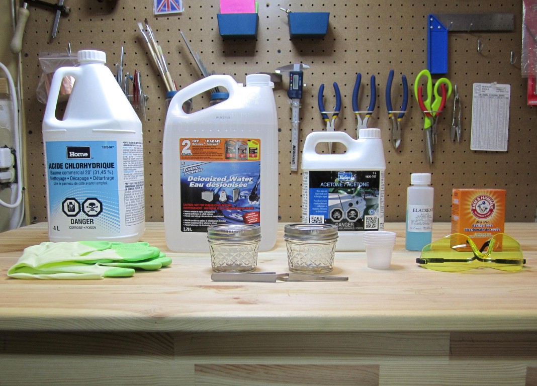
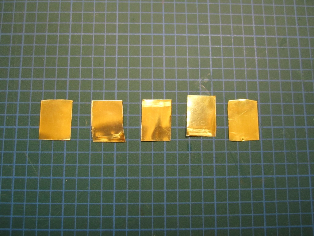
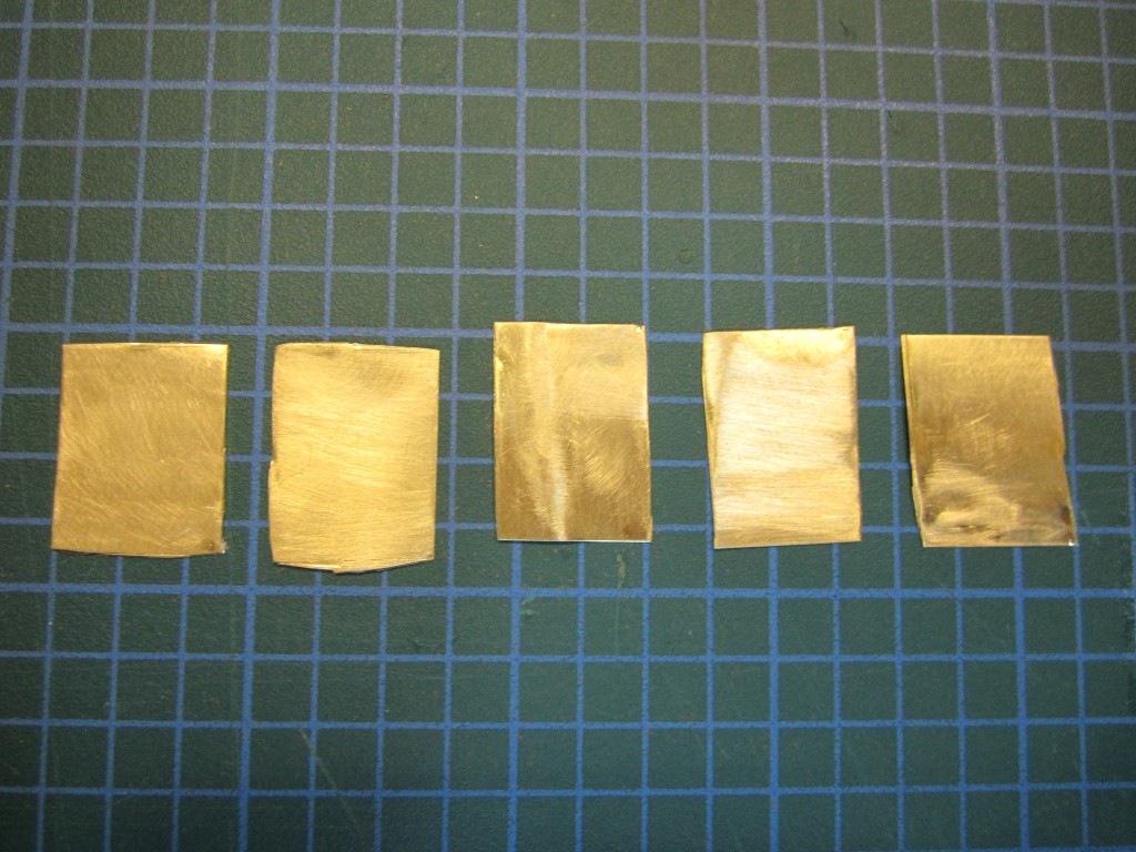
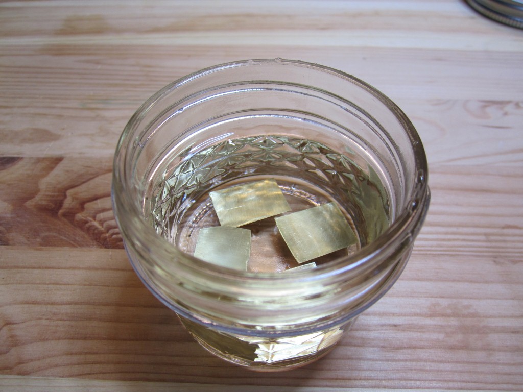
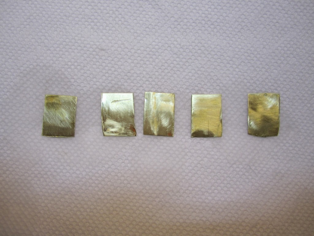
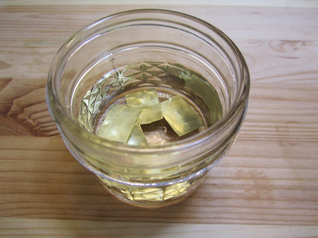
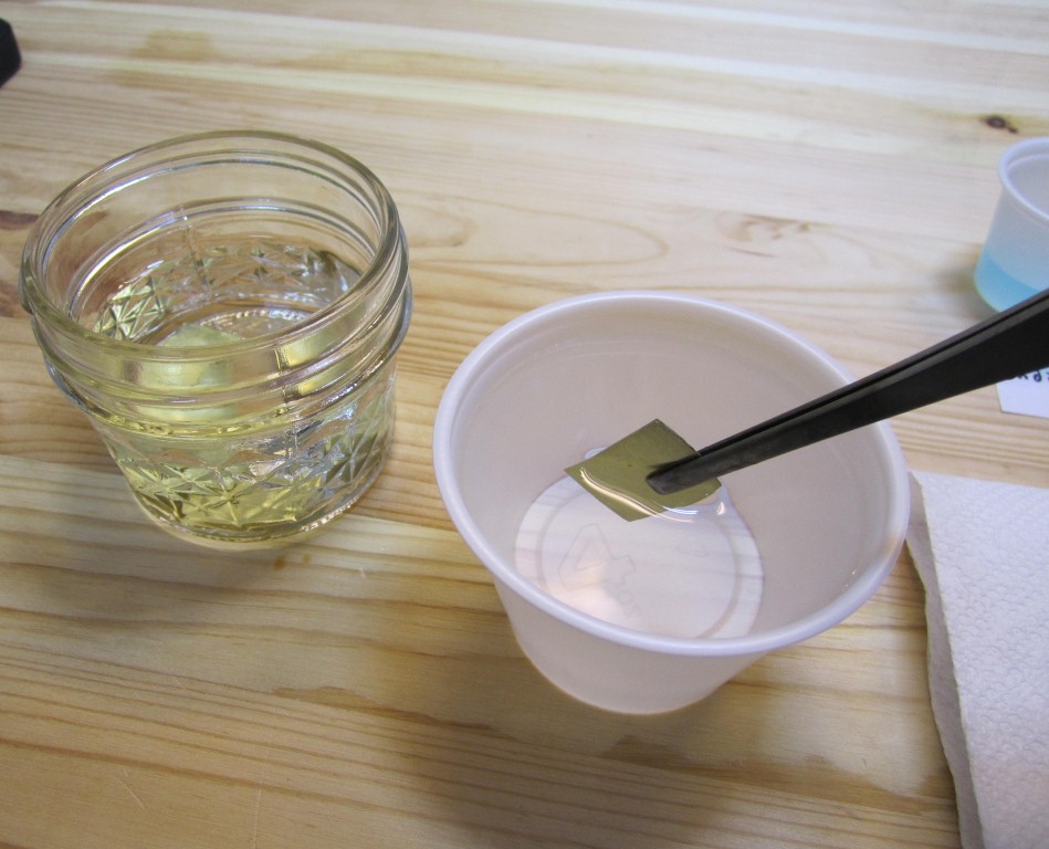
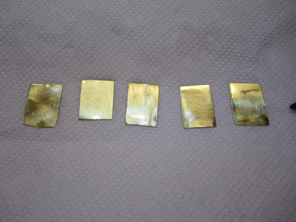
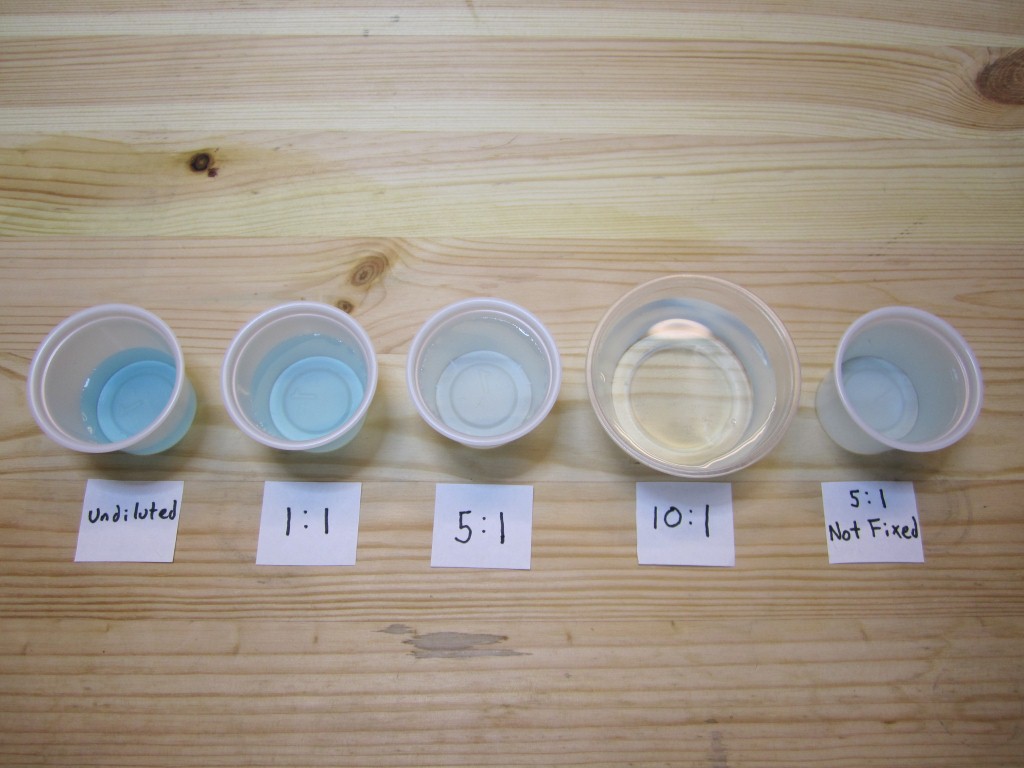
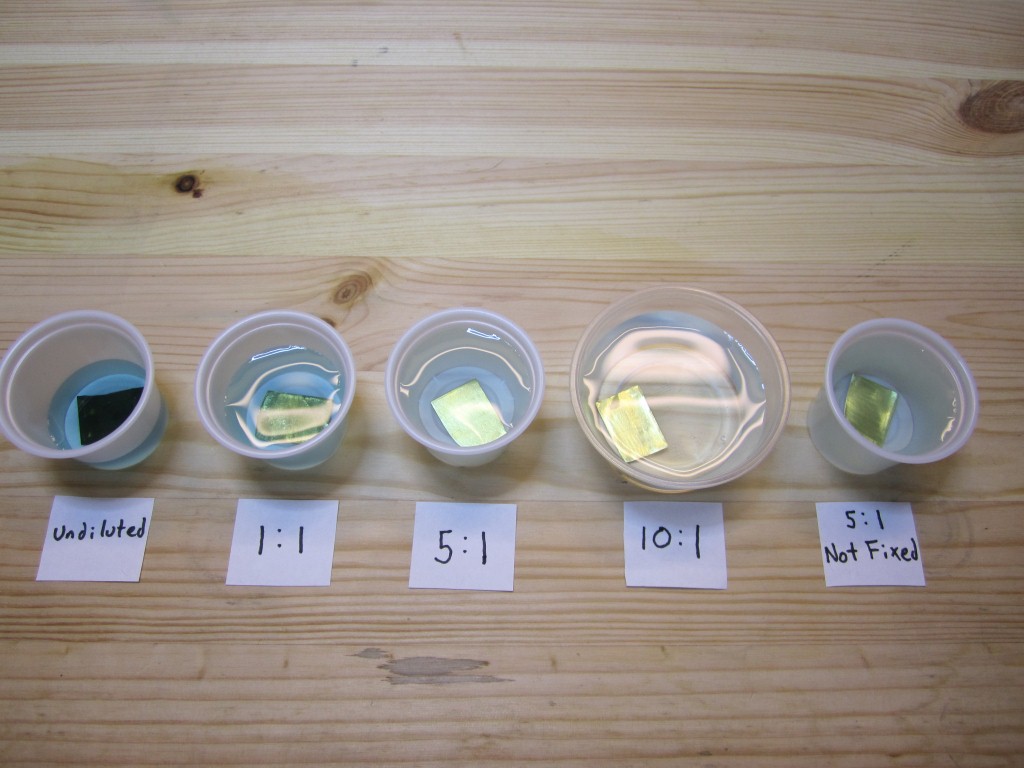
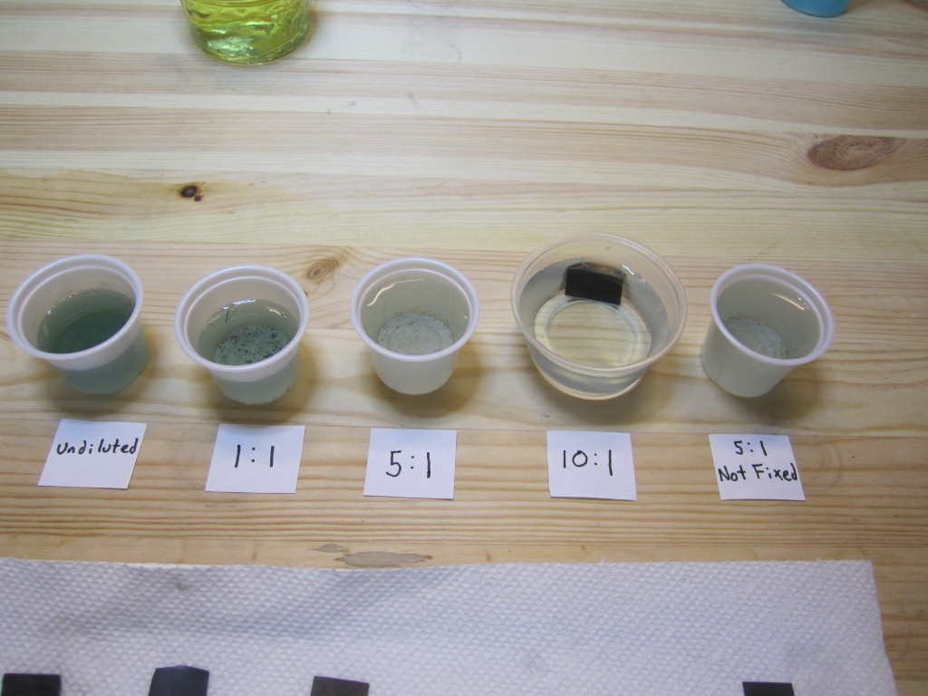
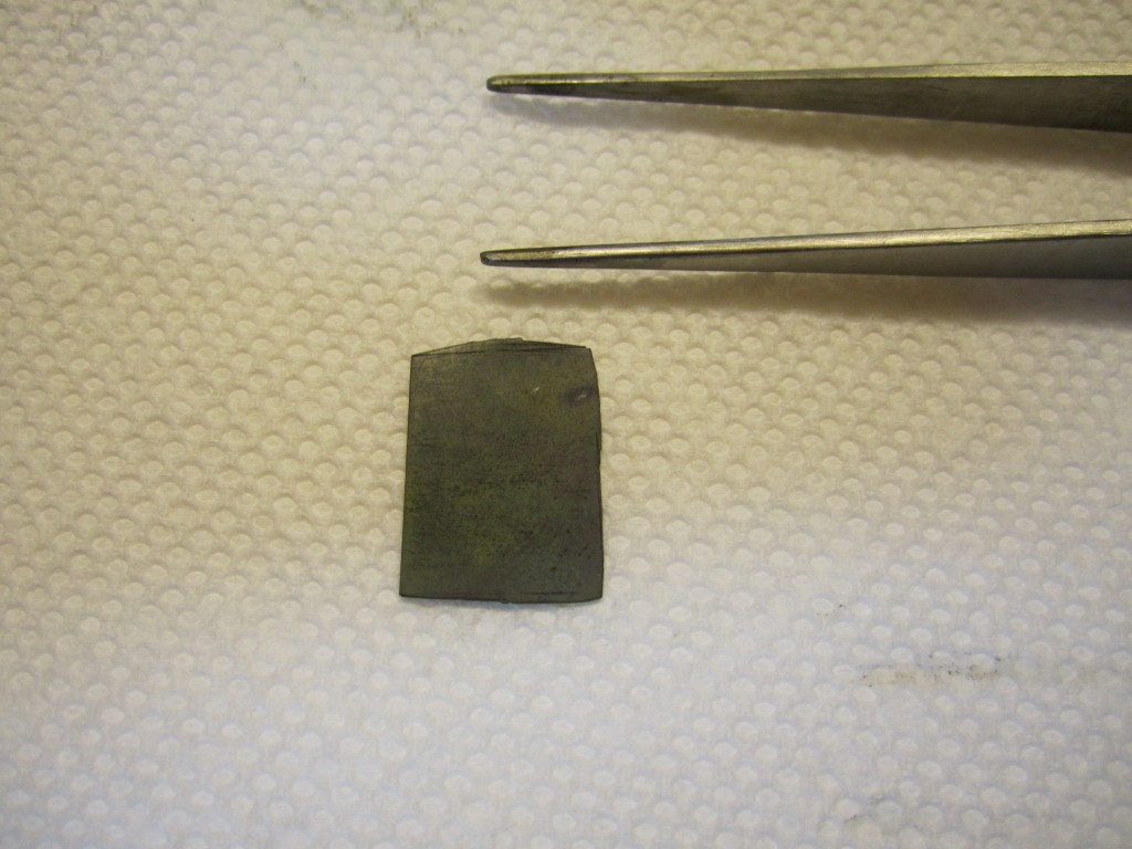
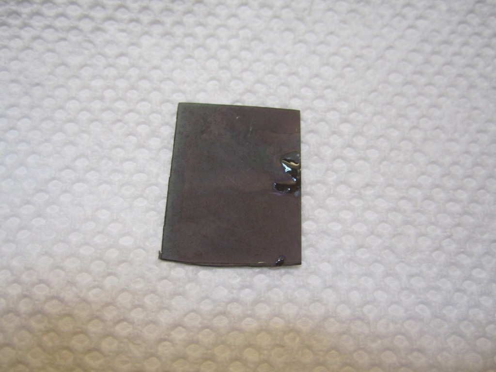
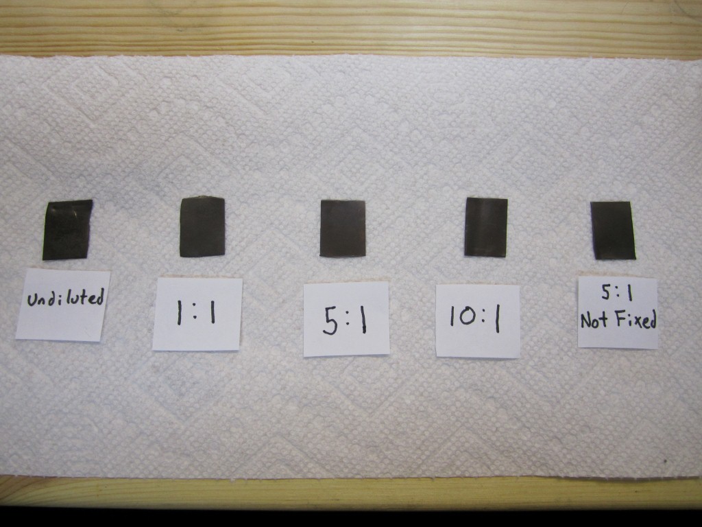
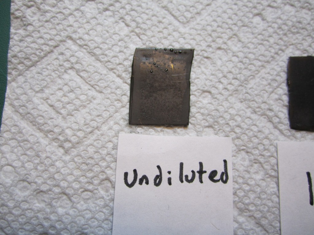
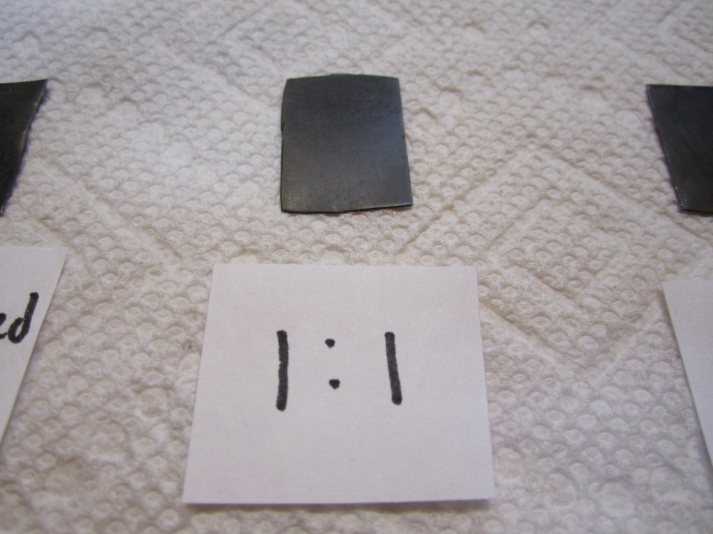
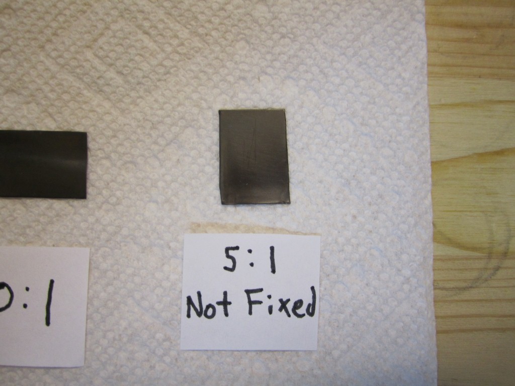
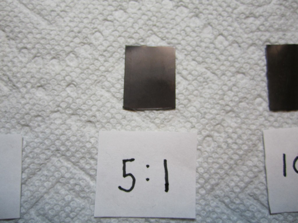
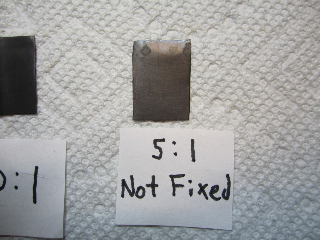
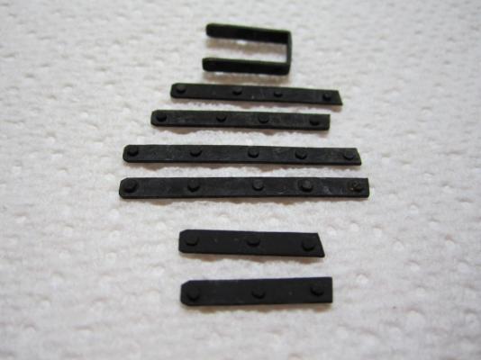
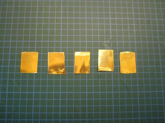
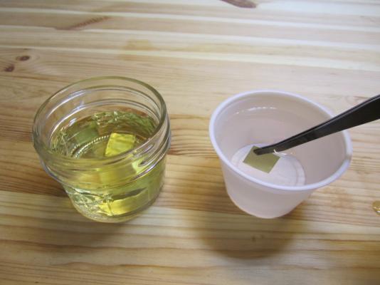
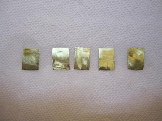
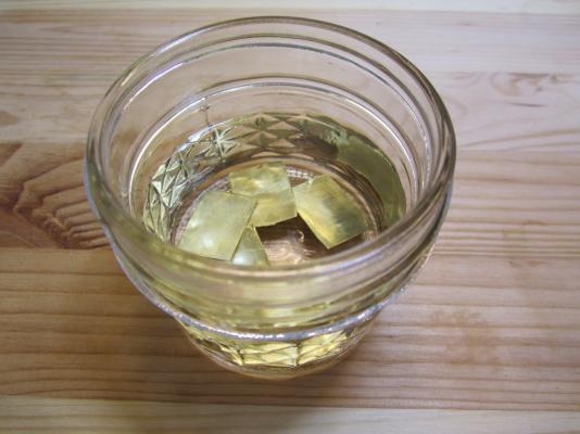
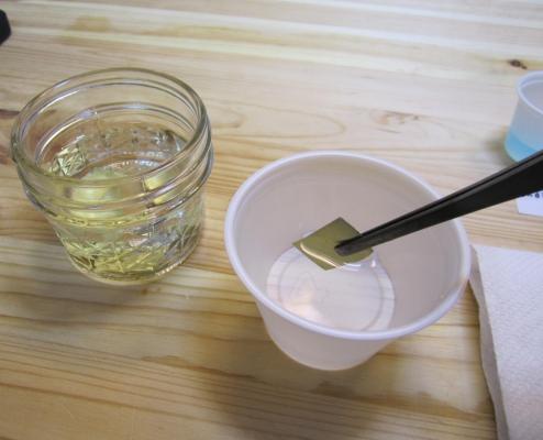
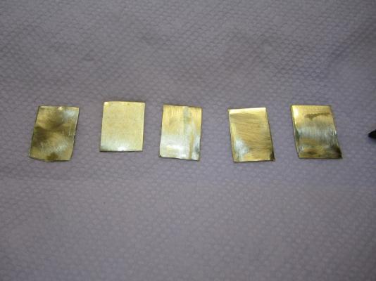
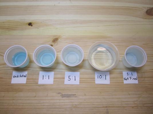
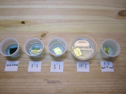
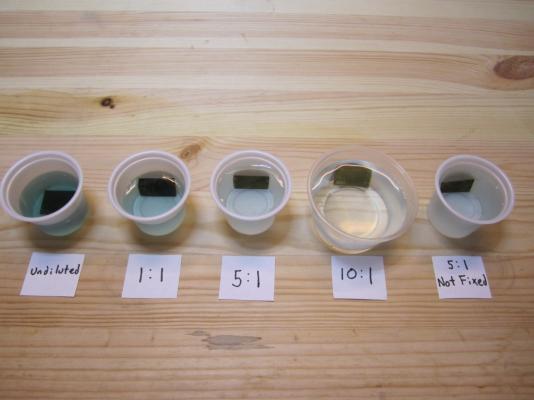
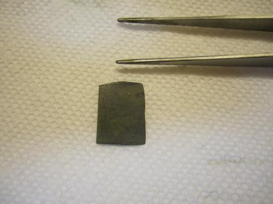
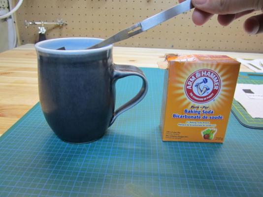
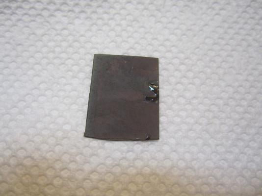
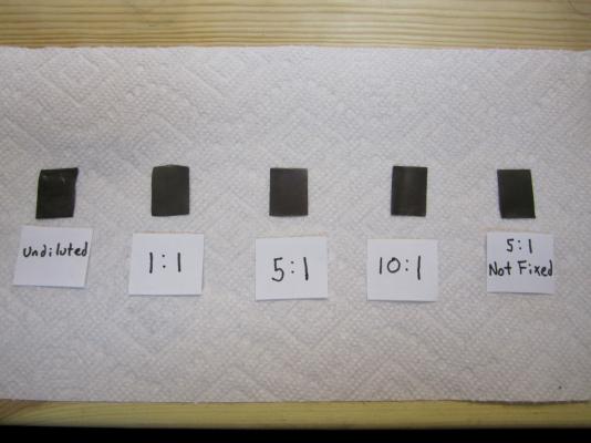
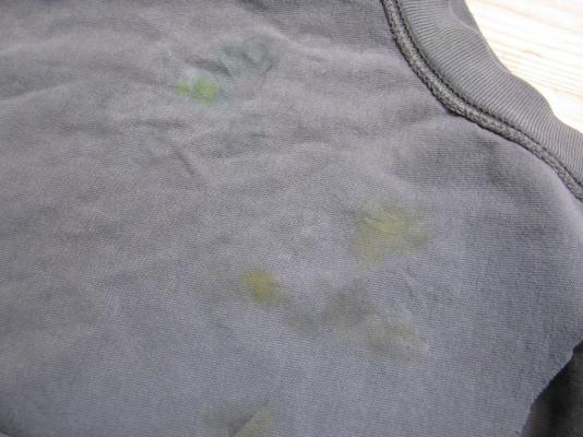
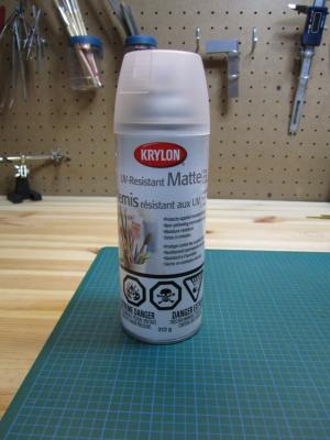
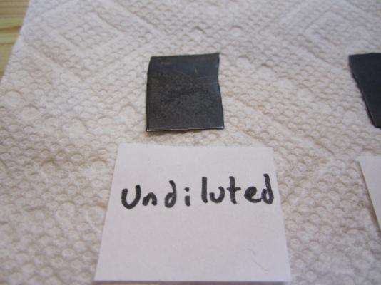
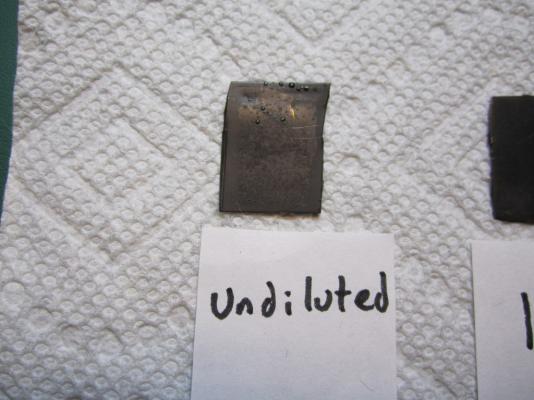
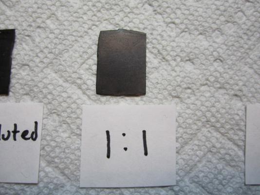
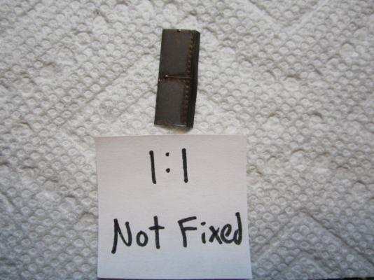
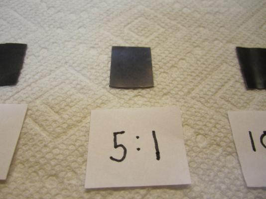
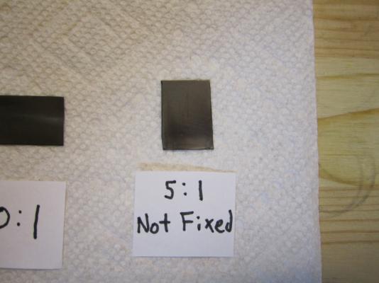
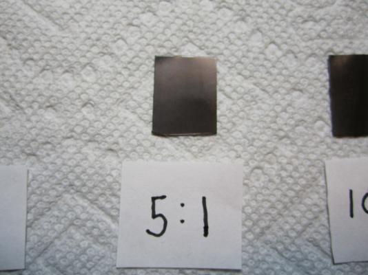
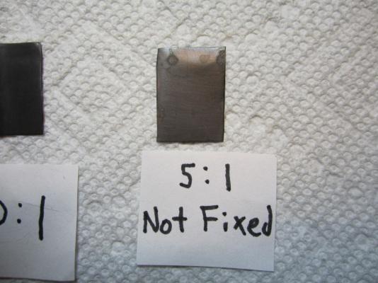
The Problem: Anyone who has followed my HMS Terror scratch build may remember my issues with blackening brass fittings for the stern assembly. To briefly summarize, I immersed the parts in a standard 8:1 mixture of Blacken-It solution mixed with bottled water, waited until the parts turned the appropriate colour, then rinsed in bottled water to “neutralize” the reaction. I tried this several times on different parts and each time it resulted in a flaky, blotchy appearance that could not be made even despite buffing with a soft cloth. Here is an image of my results. Note the blotchy and flaky texture. Inspired by the fine results of other modellers on the boards, I resolved to master the “mysteries of the blue Liquid”. I began with research; modelers, gunsmiths, jewellers, instrument makers, and mechanics all use various products and processes to chemically blacken metals and a great deal of information is available from forums, blogs, websites, magazines, and books. With this knowledge at hand, I decided to conduct a series of trials to determine the best process for blackening metal using Blacken-it. I chose Blacken-it as it seems to be the most commonly used product on Model Ship World, and, perhaps more importantly, I had a supply available. However, the techniques I use here should be applicable to other metal blackening products. Before I outline my tests I should begin with a note on safety: The chemicals used in the blackening process are dangerous. Rubber gloves, safety goggles, and a well-ventilated room (or fume hood) must be used EVERY time you handle the chemicals. The Process: From my research, I learned that producing consistently good results requires seven steps, in this order: 1) The surface of the metal should be mechanically prepared. This roughens the surface and removes synthetic coatings that are often used to give stock metal a shiny appearance. 2) The surface of the metal should be treated with an acid pickle to remove any scale or corrosion. 3) The metal should be cleaned with a solvent to remove organic contaminants such as oils, fingerprints, and other dirt. 4) The metal is chemically coloured using a diluted blackening agent. 5) The reaction should be “fixed” or halted, using a neutralizing solution. 6) The surface of the metal should be buffed to remove excess blackening products and to polish the new surface. 7) The metal should be coated in a protective agent to prevent corrosion, soiling, and damage (optional). The Equipment: My research indicates that the following chemicals most often produce consistent results: 1) Muriatic acid (31.4%). This is commonly used to remove scale and corrosion on the surface of the metal. Most hobbyists and professionals use 1:1 concentration of water and acid. Remember, you should always pour the acid into water, as it can be dangerous to pour water directly into acid. You can purchase muriatic acid in most hardware or pool supply stores. 2) Deionized water. This tip was given to me by Druxy on these forums. I’m convinced that the blotchy, scaly results on my first use of Blacken-it were the result of my use of mineral-laiden bottled water. Dionized water is treated to remove mineral ions which could react with Blacken-it. Use the deionised water for all stages of the blackening process, including rinsing between baths, diluting chemicals, and for neutralization. 3) Acetone (100%). This is a widely used degreasing agent employed to remove finger prints, oils, or other organic coatings which might contaminate the metal. It can be purchased at any hardware store. 4) Baking soda. The final stage of the blackening process should include proper neutralization. A common solution is two table-spoons of baking soda in a cup (250 ml) of warm deionised water. Often, hobbyists will use running tap water to neutralize the reaction with good results; baking soda seems to be preferred by jewelers and instrument makers. Here is a photo of the equipment I used in my tests. The Tests: My trials involved testing two variables: 1) the concentration of Blacken-It (undiluted, 1:1, 5:1, or 10:1), and 2) water neutralization versus baking soda neutralization. The test parts prior to preparation. Step 1: I thoroughly sanded the surface of my brass test parts with 400 grit sandpaper. This is similar to the preparation of any metal part even if it isn’t going to be painted or chemically coloured. Step 2: I buffed the metal with ultrafine steel wool. Be certain to carefully remove any steel wool filings that remain as they can react with the chemicals used in the next stages. The parts after mechanical preparation. Step 3: Immerse the part in muriatic acid (diluted 1:1 with deionised) water for 30 minutes. You can immerse the parts for longer, but the acid will eventually etch the surface and soften sharp edges and other details if you leave them in too long. You may notice that the pickle will change the colour of the brass or that some corrosion may appear – this is normal and is caused by impurities or inconsistencies in the metal. Step 4: Rinse each part by agitating vigorously in a bath of deionized water for at least 10 seconds. Allow to dry thoroughly on a clean paper towel. Change the water in the bath for the next step. Allow the parts to dry thoroughly. Step 5: Immerse the parts in an acetone bath for 30 minutes. Step 6: Rinse each part by agitating vigorously in a bath of deionized water for at least 10 seconds. Allow to dry thoroughly on a clean paper towel. Allow the parts to dry thoroughly. Step 7: Immerse the parts in the Blacken-it solution. Maximize the surface area of the part exposed to the chemical by placing it on end if you can. Gently, without scratching the surface, turn the part every few minutes to ensure all surfaces are exposed equally to the solution. Carefully monitor colour changes, and remove the part when the desired colour is achieved. Different concentrations of Blacken-it. The parts after 30 seconds. After five minutes. After 60 minutes (other parts removed when desired colour achieved). Step 8: Instantly dunk the part in the warm baking soda bath. Agitate vigorously for ten seconds. You will notice that the part will begin to corrode and a blotchy green or red film will cover the surface. Do not worry. After a bath in the baking soda solution, the part will appear green (or sometimes red). Neutralizing with water leaves a cleaner surface (but caution is warranted, see below). Step 8: Carefully buff the part with a clean soft cloth (an old t-shirt works perfectly). Do not touch the part with your fingers. You will notice that the corrosion products resulting from the neutralizing bath will scrub away. Buff until all portions of the part have an even colour; continue to buff if you want a shinier surface. Buffing the parts fixed in the baking soda solution removes the green/red coating. After buffing, all the parts appear roughly similar in colour and finish from a distance (see below for differences). Step 9: Wait 24 hours to ensure the reaction was effectively neutralized. If “sweating” or pitting is noticed, the reaction was not properly neutralized, and a further rinse may be required. Usually the part can be salvaged by buffing with a soft cloth. Sometimes, it may need to be blackened again. Step 10 (Optional): Spray the parts with a thin acrylic matte coating to protect the surface. I use Krylon Matte Coat. The Trial Results: Undiluted Blacken-It solution: The undiluted solution produced a very dark, but somewhat uneven black surface in about five minutes. Fixing the reaction with baking soda caused a significant amount of corrosion, but it was mostly removed by buffing. Undiluted immediately after buffing. However, after 24 hours both parts began to sweat, indicating that the chemical reaction had not been neutralized even with a baking soda bath. This is not unexpected, as the product guidelines indicate that the product is meant to be diluted. Undiluted after 24 hours. Recommendation: Do not use undiluted solution. 1:1 Blacken-it Solution This is the concentration recommended by the manufacturer. After ca. 10 minutes the part reached a deep black, but after neutralization with baking soda solution the surface appeared to be quite blotchy. After 24 hours the edges of the part began to sweat and corrode and the surface appeared pitted. 1:1 immediately after buffing. 1:1 after 24 hours. The water neutralized part had a slightly more even surface, but unfortunately began to sweat after only 24 hours. 1:1 unfixed (water neutralization) after 24 hours. Recommendation: Do not use 1:1 solution. 5:1 Blacken-it Solution The 5:1 solution required approximately 25 minutes to reach a deep black. Immersion in the baking soda solution initially produced a green corrosion but buffing resulted in an even black surface. The part remained stable after 24 hours (and is still stable a week later). 5:1 immediately after buffing. 5:1 after 24 hours. The unfixed, water-neutralized part began to corrode at the edges after 24 hours. 5:1 unfixed immediately after buffing. 5:1 unfixed after 24 hours. Recommendation: Works very well in conjunction with a baking soda rinse. 10:1 Blacken-it Solution The 10:1 solution required approximately 60 minutes to reach a dark even black. Immersion in a baking soda rinse produced a slight corrosion, but buffing resulted in a very even and deep black surface (in my opinion better than the 5:1 concentration). The part has remained stable after a week. 10:1 immediately after buffing. 10:1 after 24 hours. Similar results were achieved with the water-only neutralization, and the part remained stable after 24 hours. However, after ca. four days corrosion began to appear at the edges of the part. 10:1 unfixed after four days. Recommendation: The 10:1 solution performed very well in conjunction with a baking soda rinse, and in my opinion produced the best colour and surface. Final thoughts: 1) Fixing the parts by agitation in a warm baking soda bath appears to be a critical step in blackening brass, at least with Blacken-it. Even at lowest concentrations, and with a water-neutralizing rinse, the acidic reaction appeared to continue for some time, especially around edges and in nooks and crannies. 2) 5:1 and 10:1 solutions appear to produce relatively similar results, even though they both require proper neutralization. The 10:1 solution appears to produce a slightly more even and deeper colour. Using Blacken-it at its recommended concentration is a waste of product and results in corrosion even after proper neutralization. 3) Buffing is a critical step in achieving the proper surface appearance. 4) I was able to rejuvenate “sweating” parts by dunking them in a baking soda solution and then buffing. Regardless, faint hints of the corrosion remained.


- 52 replies
-
- 42
-

-
Harriet McGregor by Boccherini
Erebus and Terror replied to Boccherini's topic in - Build logs for subjects built 1851 - 1900
Excellent craftsmanship! -
Hi Michael, Thanks for your comment; very much appreciated! To answer your question, the rails and propeller were probably gunmetal, or red brass, so I won't be blackening them. Red brass is slightly darker and has more of a matte finish than the brass I used, but I really like the look of polished brass against the Swiss pear, so I probably won't darken it any. It should naturally tarnish some over time, so eventually it will look fairly accurate. Here is a link to a red brass flare gun if you are interested in the real look. http://www.rubylane.com/item/700632-I-11055/WWI-Flare-Gun-Webley-Scott
-
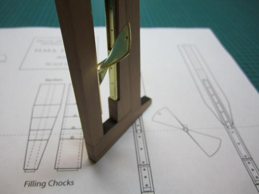
Hello Keith, Thank you for your very kind words; positive comments like this provide great motivation. To answer your question, yes, that was the design, and you can see some details here in Lang's original plan. http://collections.rmg.co.uk/collections/objects/85474.html As you can see on the planns, the aft rail didn't actually float in mid-air as it may seem from my last photos. It sat on a custom-fitted chock that was placed over the iron staple knee and then bolted to the keel. So, it was supported by a wood platform, just not one cut into the rudderpost. Though the plans don't indicate this, I suspect these wood supports added little to the structure, as the rails must have been firmly bolted along their length to each post. When I finally glue all the bits and bobs to the stern wood, I'll then have to model this custom chock. I'm a very slow builder. Thanks again for your comments!
- 346 replies
-
- 3
-
-
- terror
- polar exploration
- (and 2 more)
-
Thank you everyone for the positive comments and likes; they are a source of great motivation for me. Druxey and David B., yes I think it would have been very tricky work to unship the propeller when at sea. Most systems of the era used a frame to aid the process. The frame was continuously chained or tied to the tackle so it could easily be raised. I'm not certain why the hole in the propeller blade system was adopted. It is very rare. I can only find two instances of it ever being used; on HMS Erebus and Terror, and some 55 years later on the RRS Discovery. All are polar vessels so there must have been some advantage to this over the frame system. I think, perhaps, that it has to do with potential damage to the frame. If the frame was warped by the ice, it might have been impossible to remove the propeller. The hole in the propeller system was simpler; less parts to damage and cause problems. Crackers, yes indeed I hope that the Parks Canada team finds the ships! Hopefully they will be intact like the Investigator and Breadalbane. However, they are very small ships (ca. 100 feet) and if they were too severely damaged it could be very difficult to locate them.
-
Druxey, thank you for the kind words. Yes that is the plan; I don't intend to glue the propeller in place. When I am finished the chocks I'll be able to show her in her sailing configuration. The propeller glides nicely along the rails, though I made the fit tight enough that it can be held in any position by friction.
-
Beautiful. Your patience and precision are paying off wonderfully. And thank you for the step-by-step tutorial!
- 3,618 replies
-
- 1
-
-
- young america
- clipper
- (and 1 more)
-
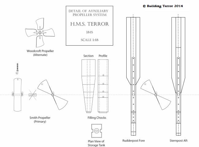
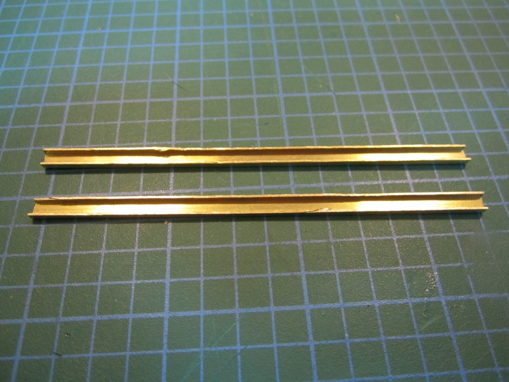
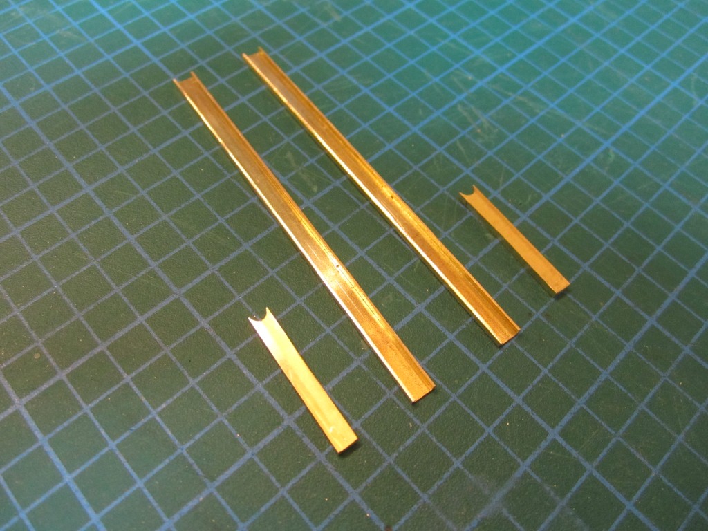
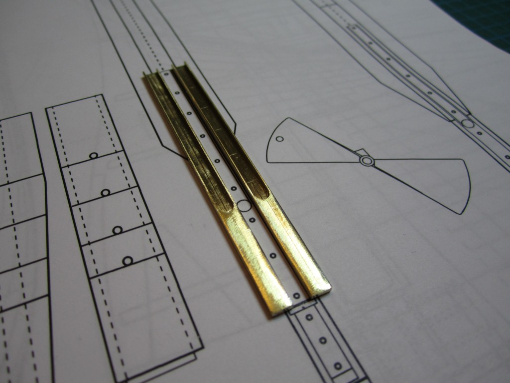
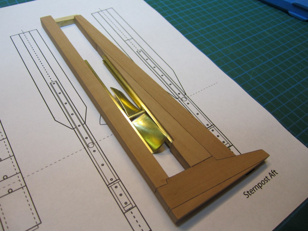
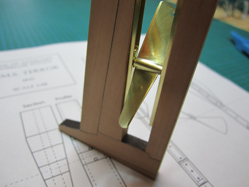
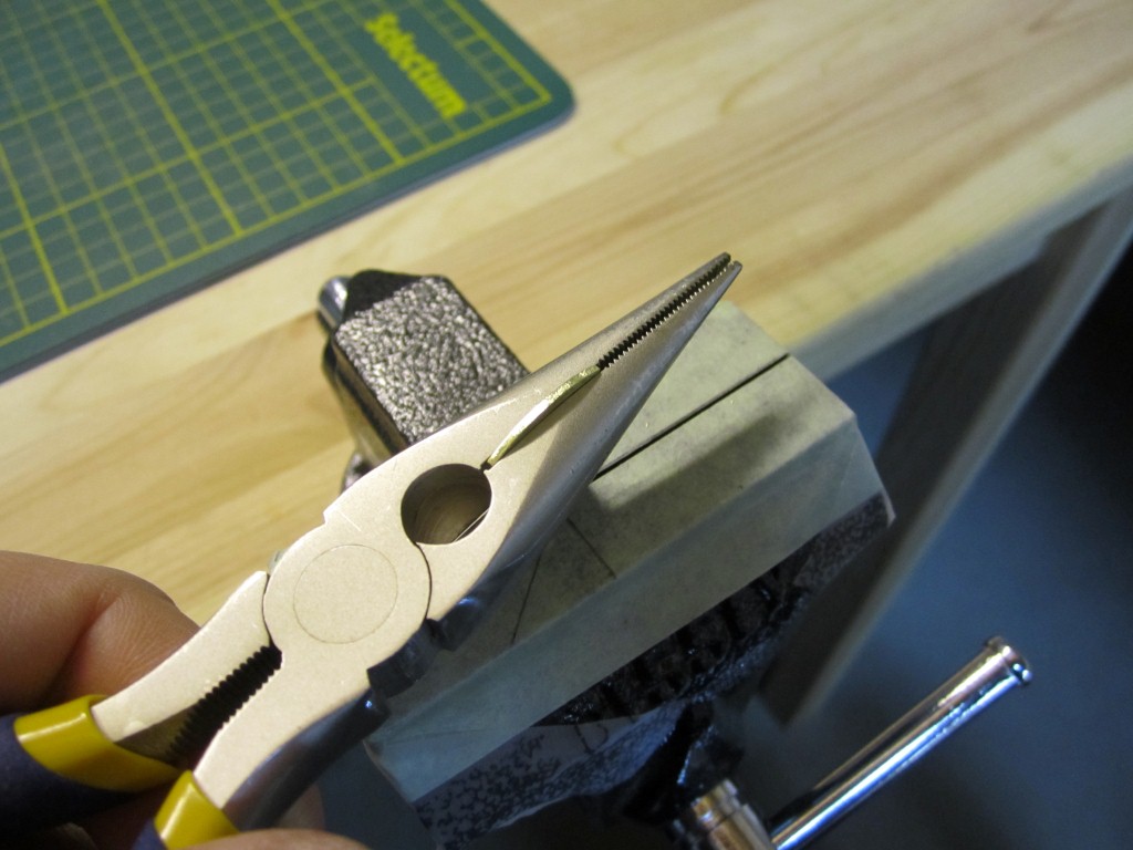
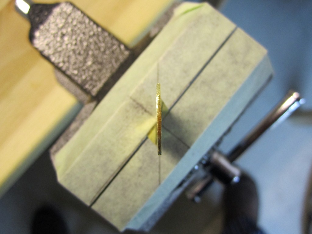
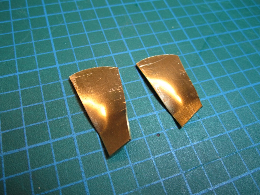
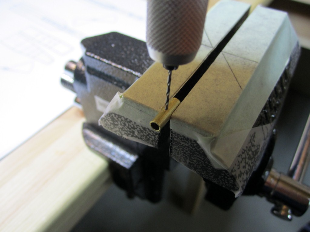
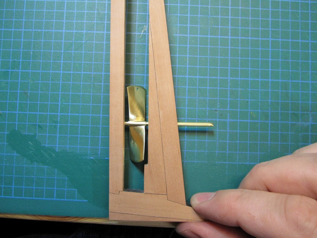
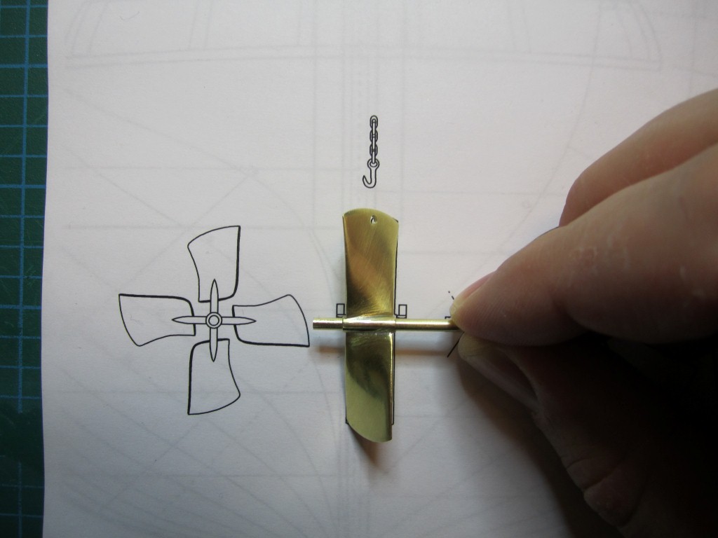
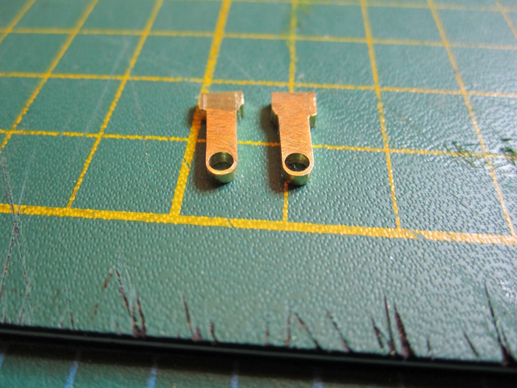
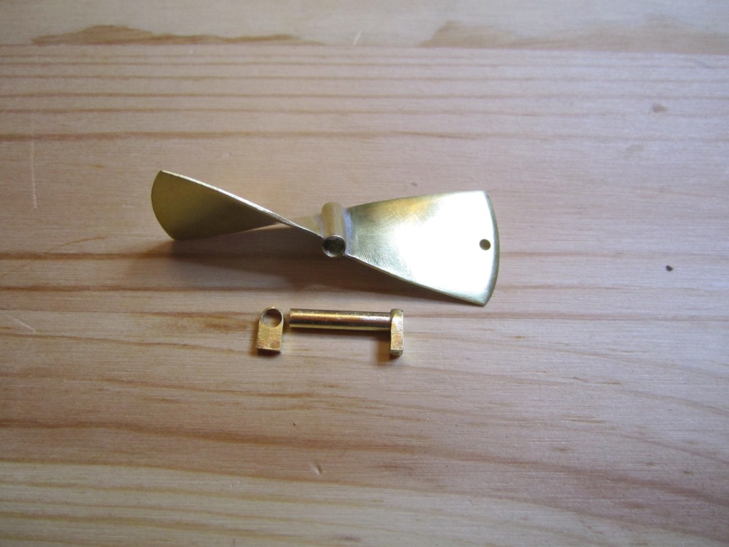
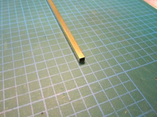
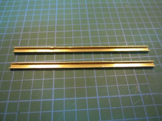
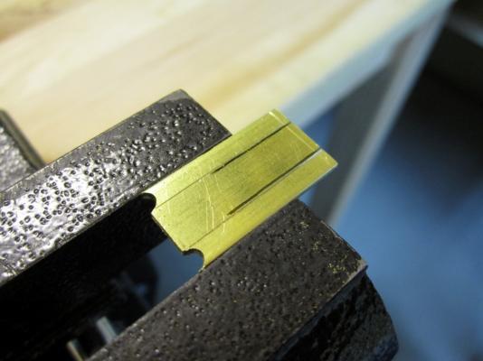
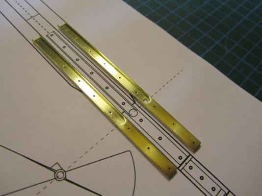
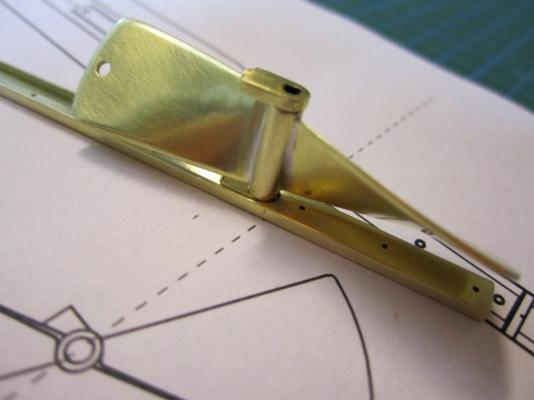
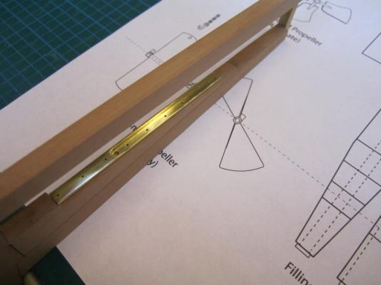
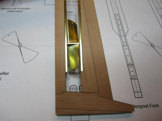
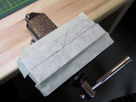
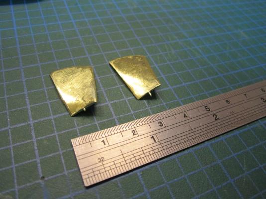
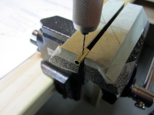
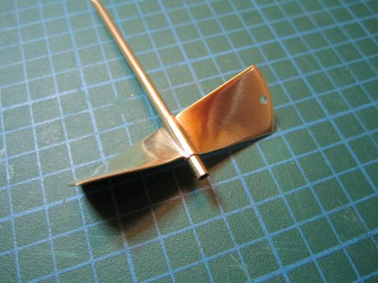
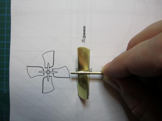
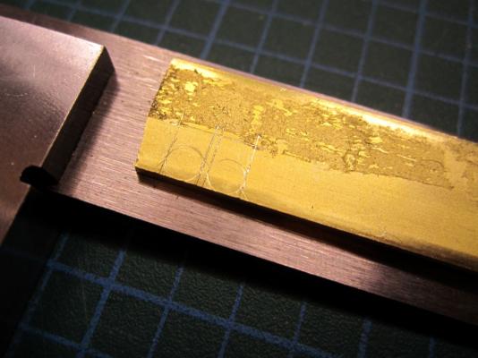
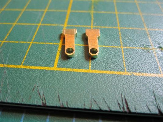
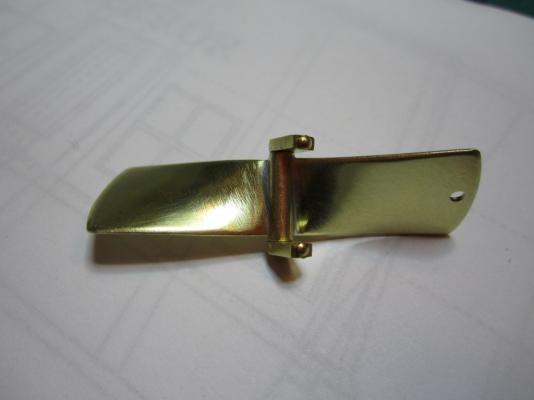
ON RAILS: RAISING AND LOWERING TERROR’S SCREW On ships like HMS Rattler (launched two years prior to the Franklin Expedition) unshipping the propeller involved a difficult operation involving tackle over the side of the vessel. A significant advancement of HMS Terror and Erebus was a new well system used to raise and lower the propeller directly through the stern of the vessels. The well system was so novel and efficient that a demonstration comparing the unshipping procedures of the Rattler and Erebus was conducted for the Lords of the Admiralty and the press prior to the departure of the vessels (Anonymous 1845:279). The system was subsequently adopted on all screw powered vessels in the Royal Navy of the era. A significant trait of the new propeller well system was a pair of grooves or rails on the fore and aft sides of the rudderpost and sternpost, respectively. These grooves were used to guide the propeller as it was raised and lowered and to seat it firmly while it was in use. On most ships, these grooves were cut into the wood of the sternpost and rudderpost, but Oliver Lang’s design for HMS Erebus and Terror needed to be different. In his design the grooves were cut into rails which projected into the well and performed two functions: 1) the rails guided and seated the propeller when it was in use and 2) they secured the filling chocks that were to be used to strengthen the stern when the propeller wasn’t shipped. Unlike many Royal Navy vessels of the era, the 1845 stern plans for the ships show that rails were straight-sided, presumably because they needed to be smooth for the filling chocks to slide along their length (most rail systems of the era bulged laterally at the position where the propeller was seated). Details of the interior of these rails are not shown on the plans, but we can assume that they included a semi-circular seat for the propeller, similar to other rail systems of the era (see here and here). The fore rail would have included an aperture for the propeller shaft, which likely telescoped through this opening to fit in the hub of the propeller (Battersby and Carney 2011:206). The rails needed to be extremely robust to take pressure from pack ice; so they were likely over-fastened – on my version I included bolts at roughly the same interval as those used on Terror’s iron staple knee. The 1845 plans reveal that the rails were made from gunmetal or a similar alloy, but given the ice abuse they would need to withstand, I believe the bolts used to secure them may have been made from iron. References: Anonymous, 1845 The Arctic Expedition. Literary Gazette: Journal of the Belles Lettres, Arts, Science, &c. for the Year 1845. Pp. 279. Robson, Levey, and Franklyn, London. Battersby, William, and Carney, Peter 2011 Equipping HM Ships Erebus and Terror, 1845. International Journal for the History of Engineering & Technology 81(2):192-211. Sectional Plans for HMS Terror's Auxiliary Propeller System. I used brass tube stock with an interior diameter slightly larger than the propeller hub to make the rails. Tube stock cut in half and filed to the correct dimensions. Cutting inserts for the heel of the rails. The seat for the propeller can be seen on the left. Parts before soldering. The rails after soldering and cleanup. The scribe lines mark the position of the bolt holes. The finished drilled pieces after polishing. The aperture for the telescoping coupling can be seen on the right. Test fit of the propeller. Another angle. Dry fit of the fore rail. Dry fit of the propeller and rails in proper position. I admit I like the contrast between the brass and Swiss pear. View looking forward. The scribe lines in the rudderpost mark where the rudder groove will be cut. Port view. Again, just a dry fit prior to final assembly and finishing.


- 346 replies
-
- 18
-
-
- terror
- polar exploration
- (and 2 more)
-
Yikes! My gudgeons are sweating!!
Erebus and Terror replied to src's topic in Metal Work, Soldering and Metal Fittings
Hello Sam, I think I might have something to contribute on this mystery. I have been experimenting with Blacken-it (will post my results someday soon), and recently ran into an issue with sweating on some brass test pieces. In both cases I prepared the pieces with a muriatic acid pickle, followed by a deionized water rinse, then an acetone bath, and another deionized water rinse. Both pieces were then placed in undiluted Blacken-it and agitated until the desired colour was obtained. In both instances I DID NOT rinse with water (or water with baking soda), after using the Blacken-it. I simply forgot to do this because I was so happy at finally achieving an even, non-flaky finish. I buffed them with a soft cloth and left them on my work-bench, happy with a good result. Here is where it gets interesting. One of the parts was left on the base of a flat steel table lamp, the other on my rubber/plastic cutting mat. When I came down to my workroom the next day I noticed that the piece on the table-lamp was damp - when I wiped my finger across it, the black surface smeared off like ink, leaving a copper-tinged streak across the metal. The other piece looked perfectly fine. A day later, however, the piece on the mat also started to sweat, but to a much lesser degree. My conclusion is that the chemical reaction was still ongoing in both pieces, and had been sped along by contact with the steel table lamp in the first piece (a sort of electrolysis, I assume). I think this is because I forgot to neutralize the pieces prior to buffing them. Sam, I noticed in your post that you didn't rinse the pieces to neutralize the reaction at the end of the blackening process. Many use water for this, but perhaps a weak solution of baking soda and water might be prudent. Just my two cents - the mysteries of the blue liquid are still eluding me. Someday I'll do a post about my findings - when I finally figure out a process that results in good, stable, results. -
Great work as always and an interesting discussion about the differences in wood/iron production. I'm convinced that a large amount of the wood used on the "fir-built" RN ships in the first half of the 19th century came from New Brunswick, Canada, and other locations in eastern North America.
-
Excellent work. I like the use if the monofilament. I'm surprised that at least some of these knees wren't made from iron. Interesting construction with the offset pillars.
-
Beautiful as always!
-
Harriet McGregor by Boccherini
Erebus and Terror replied to Boccherini's topic in - Build logs for subjects built 1851 - 1900
Very nice metal work. She looks wonderful! -
Thank you for the kind words David. I have considered publishing it in some way when I'm done - we'll see how it goes. Partly it depends on if Parks Canada can locate the the ships. If the vessels are intact, my research might become a little redundant!
-
Beautiful Ed, thanks for posting your techniques with the LOS.
-
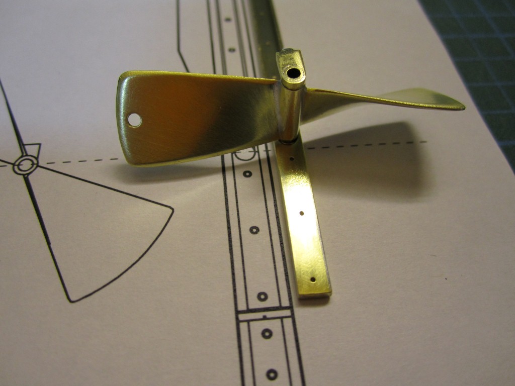
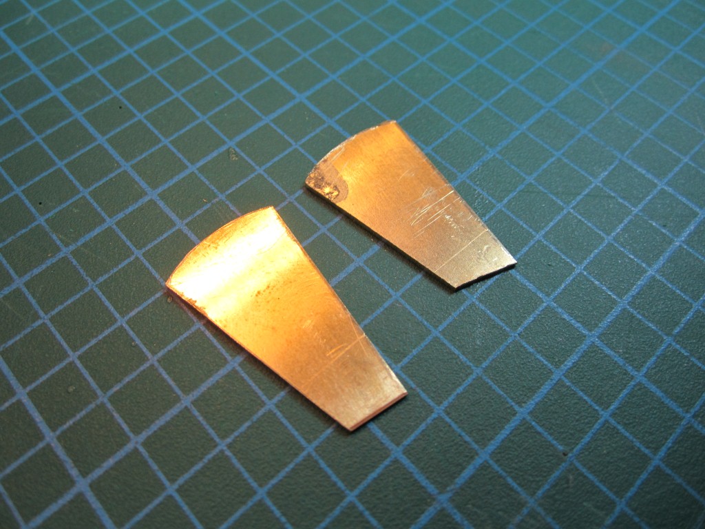
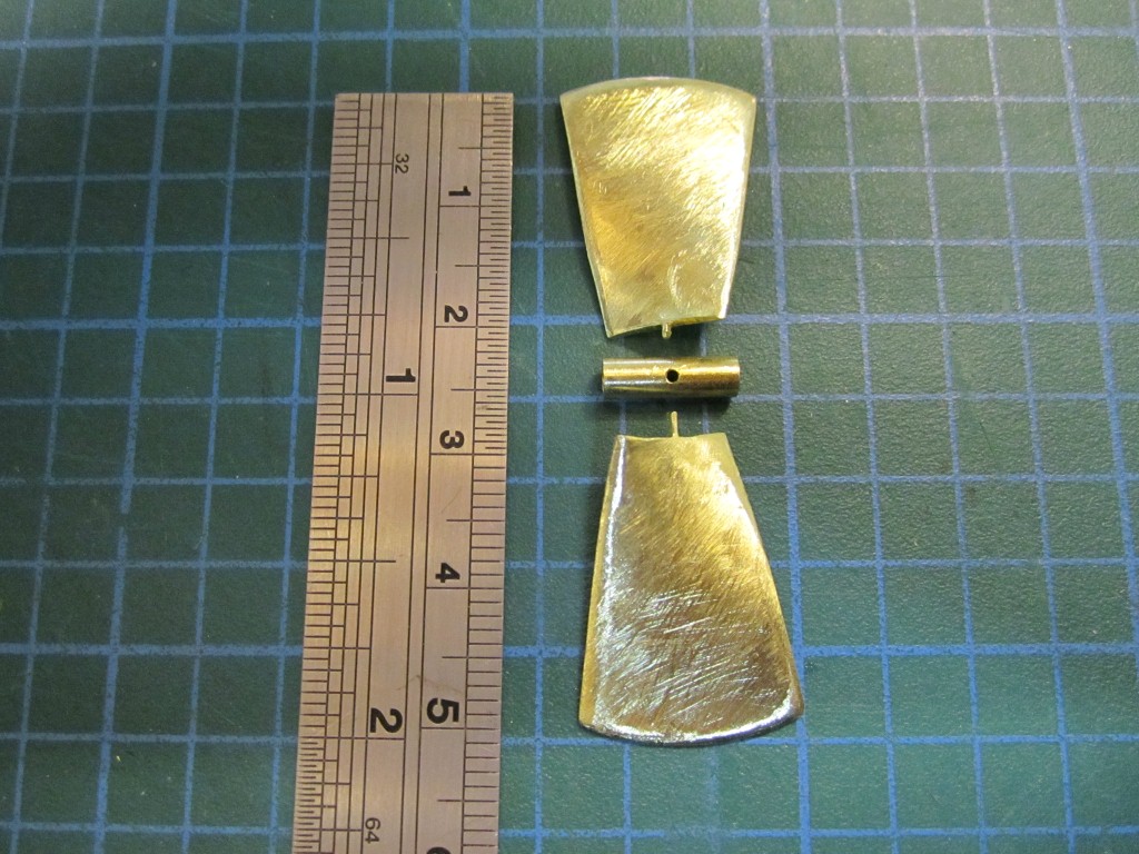
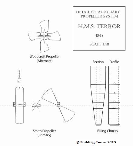
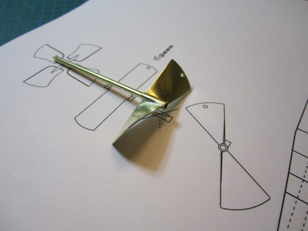
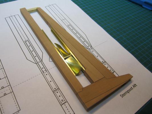
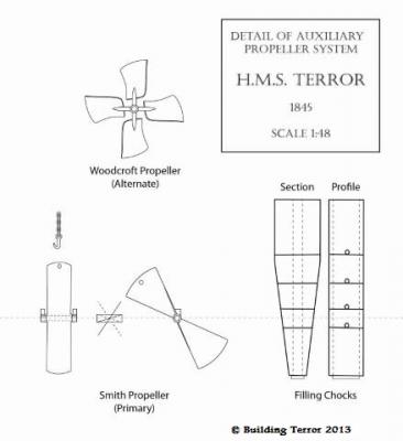
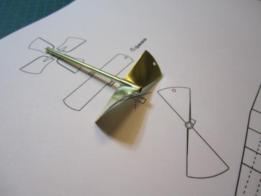
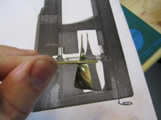
HMS TERROR’S SCREW PROPELLER Having completed the Royal Navy’s last great journey of exploration under sail power, HMS Terror’s next commission was destined to be the first major voyage of discovery to use auxiliary screw propulsion. The 1845 stern plans show that Oliver Lang chose a two-bladed Smith type propeller for the voyage (Battersby and Carney 2011:204). This choice makes perfect sense; in January of 1845 the Admiralty had just concluded extensive tests of screw propellers on HMS Rattler, finally settling on a two-bladed design by Smith (Carlton 2012:6; see also Bourne 1855:136).The propeller was likely made of gunmetal, similar to those used in subsequent Franklin search vessels (Dickens 1850:8) and other Royal Navy ships of the era. According to Lang’s plans, the screw was ca. 6 feet 11 inches in diameter (from tip to tip). HMS Erebus and Terror also carried a spare four-bladed propeller of the Woodcroft type (Battersby and Carney 2011:204). Roughly the same diameter as the Smith propeller, its shape and size would have necessitated that it be unshipped over the side of the vessel rather than through the propeller well. Plans for HMS Terror's Propeller. The filling chocks used when the propeller was unshipped are on the right. Following others (Battersby and Carney 2011:204), I originally believed that the propeller was set in a frame that would sit flush inside the fore and aft rails/grooves in the propeller well (the rail system will be described in my next post). This was a prudent assumption, as a frame-mounted propeller was standard in screw-assisted vessels of the Royal Navy in the latter half of the 19th century. The frame was an important feature because it was used to raise and lower the propeller along the rails in the well, while providing stability while it was in use. However, despite their common use in the era, I was puzzled by the fact that no frame is visible in the 1845 stern plan. I recently purchased high resolution scans of the plan, which permitted me to read Lang’s thorough annotations. Needless to say, the last annotation in the list, labeled “P”, describes the reason that Lang didn’t include a frame in the plan: “P: Propeller in place with a hole in the end of the fan to take it up by and to lower it down in place when required.“ The annotation exposes the highly expedient and experimental nature of the design, which represented a great simplification of the complex propeller lifting system used for the Rattler (view it here). While very rare, the hole-in-blade lifting system was subsequently employed on the RRS Discovery by Robert Falcon Scott during his 1901 Antarctic Expedition (pictures of the hole in the blade can be found here and here). In fact, the RRS Discovery appears to have borrowed many design elements from the Erebus and Terror, a testament to the advanced and efficient nature of their systems. Because Lang’s plans don’t show precisely how the propeller articulated with the rails in the well (the rails on the plan obscure those details), I was forced to speculate that the propeller included two retaining ferrules which would both seat the propeller and guide it as it was raised and lowered into position along the rails. In modeling this, I took inspiration from the ferrules used in contemporary Admiralty models and the RSS Discovery, though I admit they are highly generalized and speculative. References: Battersby, William, and Carney, Peter 2011 Equipping HM Ships Erebus and Terror, 1845. International Journal for the History of Engineering & Technology 81(2):192-211. Bourne, John 1855 A Treatise on the Screw Propeller with Various Suggestions for Improvement. Longman, Brown, Green, and Longmans, London. Carlton, John 2012 Marine Propellers and Propulsion. Butterworth-Heinemann, Oxford. Dickens, Charles 1850 A Visit to the Arctic Discovery Ships. Household Words: A Weekly Journal 1:8. Propeller blades cut from brass strip stock. A guide for bending the blades to the proper angle. Bending the blade by hand. Checking the angle. Blades after bending. Rough filed to shape, with posts for attachment to the hub. The hub is made from brass tube stock. Parts prior to assembly. The finished propeller, including the hole in the blade. The blades were silver -soldered to the hub, then the entire piece was sanded with 400 grit sandpaper and buffed with superfine steel wool. Compared to the plans. Assessing the profile shape. Comparing the prop to the model of HMS Rattler in the NMM. Checking fit in the well. Marking brass stock to fabricate the ferrules. Ferrules roughed out. Prior to final assembly. The ferrules are glued in place with metal epoxy, rather than soldered. The finished part - yes, it spins!


- 346 replies
-
- 21
-
-
- terror
- polar exploration
- (and 2 more)
-
Your metal work never fails to amaze me.
-
Oh dear that's not good. I wonder if he even knows that he's posted it online - I can't see a link to it on the rest of the site, or to the "stuff folder" he's placed it in.
-
This looks so good. Amazing work. Thanks for sharing.
-
Thanks very much for posting your wax tests. Very useful indeed. And the LOS and copper does seem to work incredibly well!