HOLIDAY DONATION DRIVE - SUPPORT MSW - DO YOUR PART TO KEEP THIS GREAT FORUM GOING! (Only 13 donations so far - C'mon guys!)
×

Erebus and Terror
-
Posts
410 -
Joined
-
Last visited
Content Type
Profiles
Forums
Gallery
Events
Everything posted by Erebus and Terror
-
 Beautiful, inspirational, work!
 -
Michael, Sincere thanks for those very kind words. I've enjoyed following your beautiful builds (and learned a lot in the process).
- 346 replies
-
- 4
-

-
- terror
- polar exploration
- (and 2 more)
-
Thanks for the posts Debbie and Mark - I'm keeping my eye on these and maybe a fourth or fifth generation will be in my future. Until then, I'll keep visiting my local library (they make one available to the public).
-
Thanks everyone again for the comments and likes. Coming from artists I admire so much, they mean a great deal to me. Cheers, E&T
- 346 replies
-
- 1
-
-
- terror
- polar exploration
- (and 2 more)
-
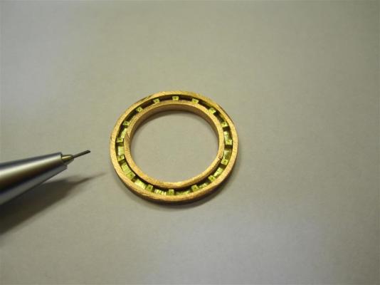
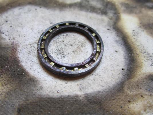
Thanks everyone for the comments and likes. I really appreciate it. Greg, I use a product that Druxey recommended to me some time ago, called Jax brass and copper black (http://www.jaxchemical.com/jaxshop/shopexd.asp?id=45). I mix it about 8:1 with deionized water. It's far superior to "Blacken-It", which I've had no end of troubles with. This is the first time I've used copper solder and I'm really impressed with the results; once it's blackened you can't see the seam at all.
- 346 replies
-
- 5
-
-
- terror
- polar exploration
- (and 2 more)
-
Thank you Druxey! I did have some sore fingers after all the filing. I had thought to use only six pawls to show off the pawl rim, but my conscience wouldn't allow it!
- 346 replies
-
- 6
-
-
- terror
- polar exploration
- (and 2 more)
-
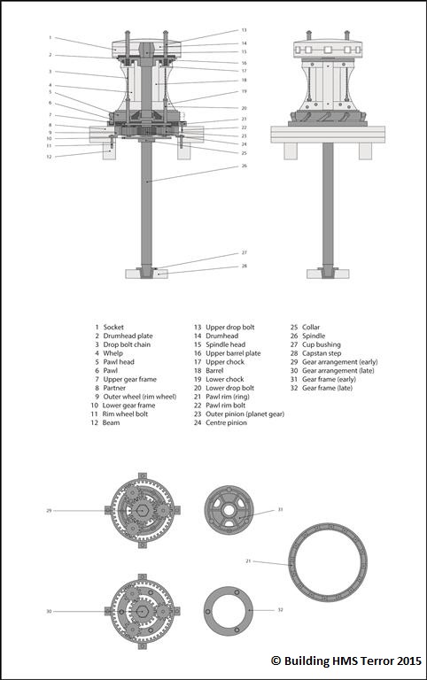
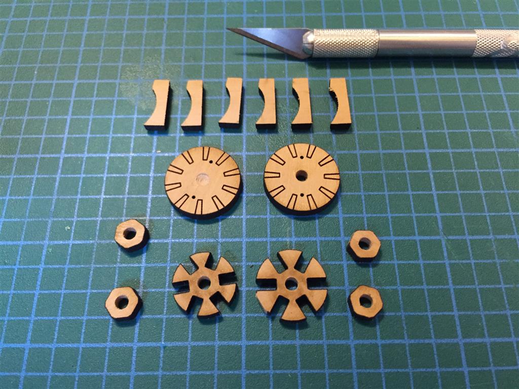
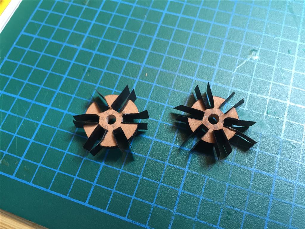
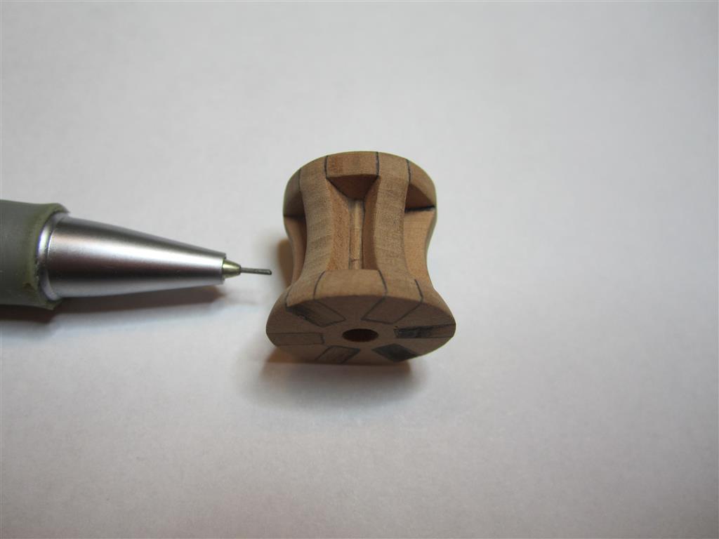
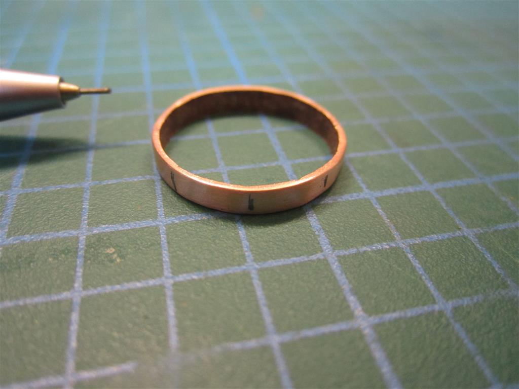
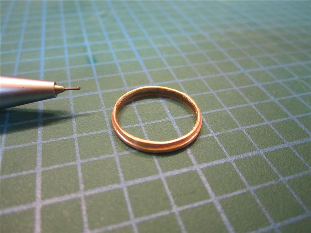
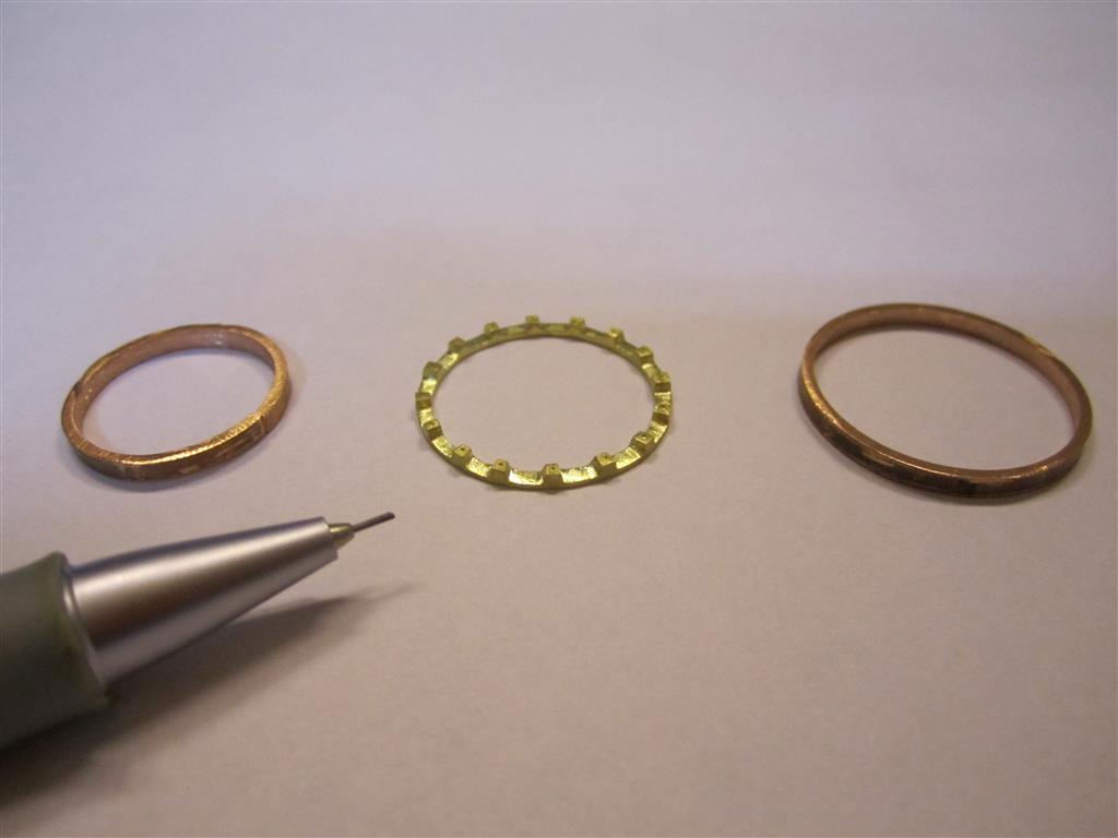
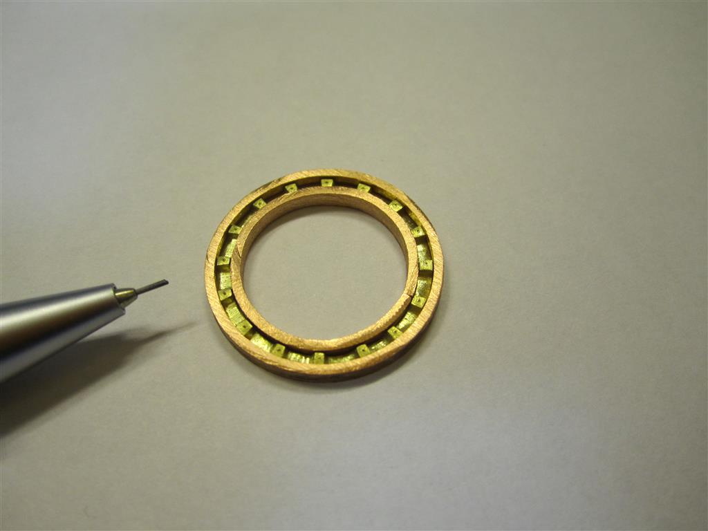
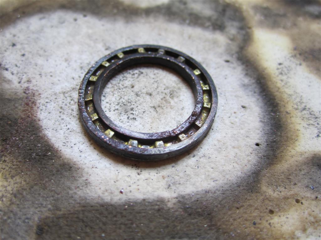
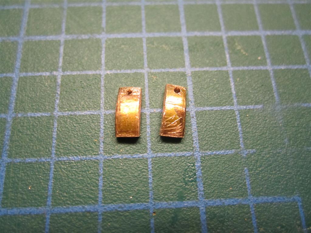
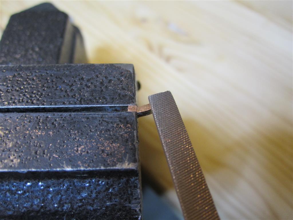
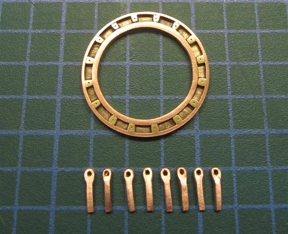
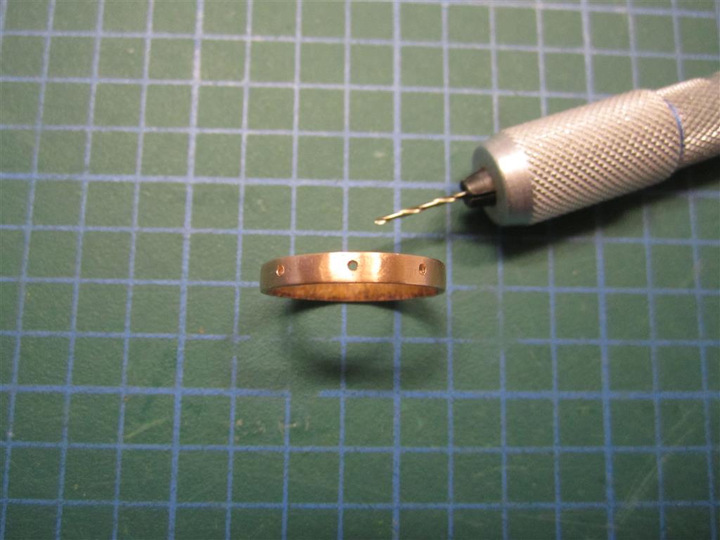
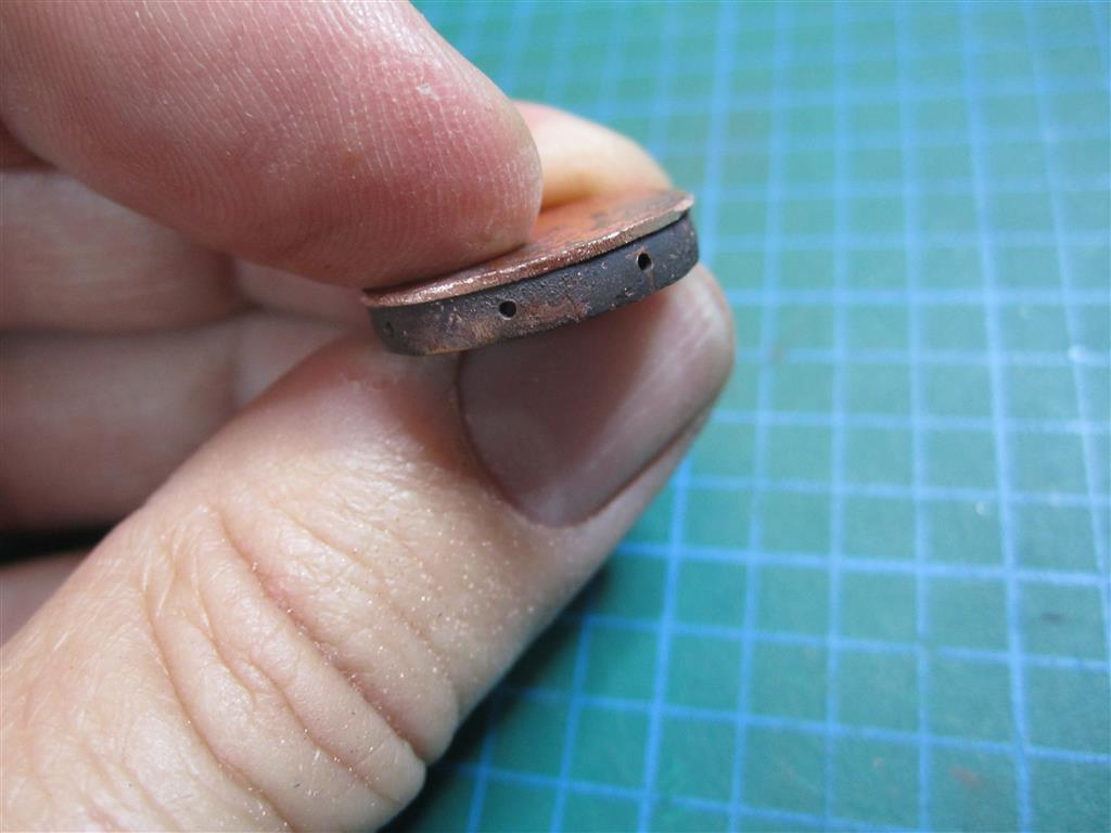
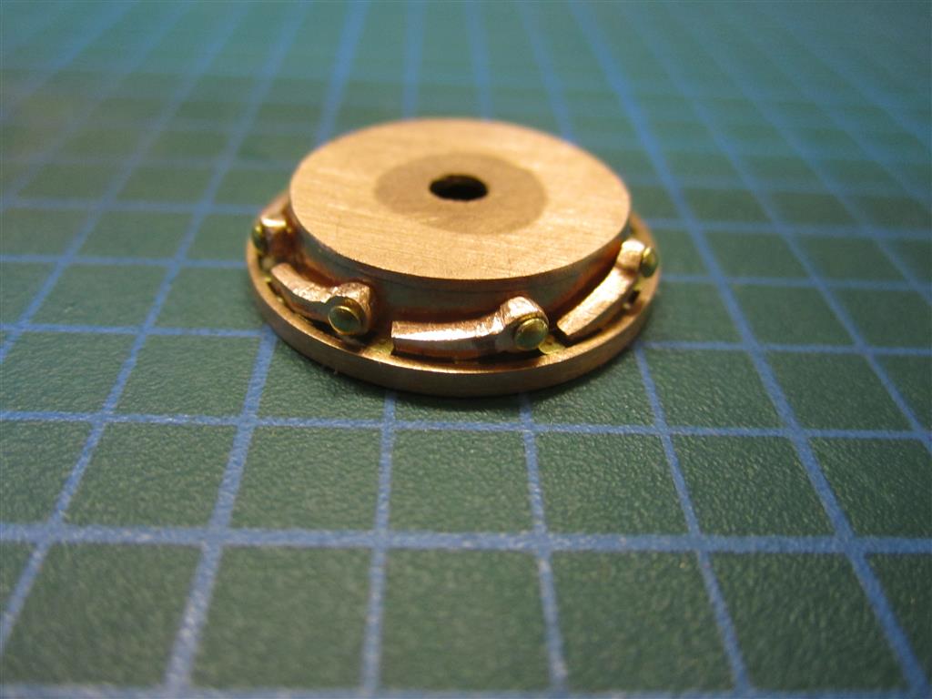
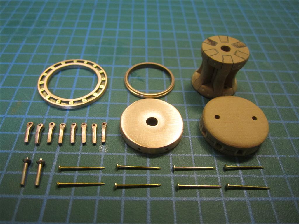
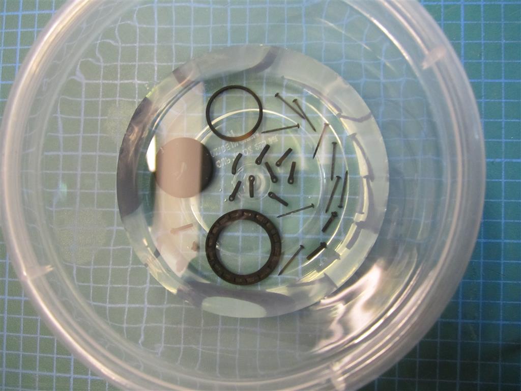
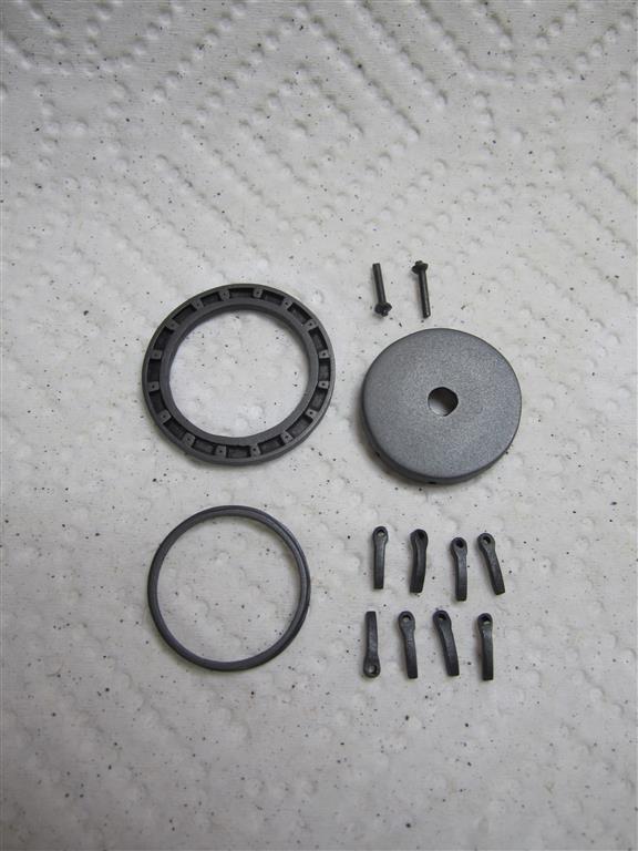
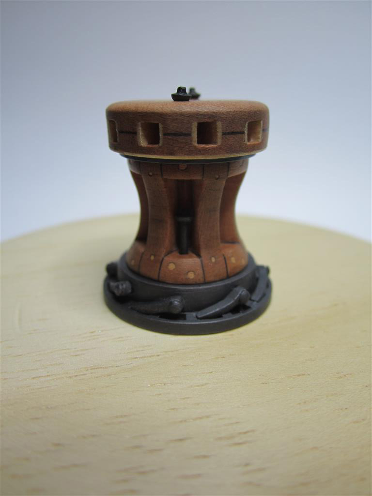
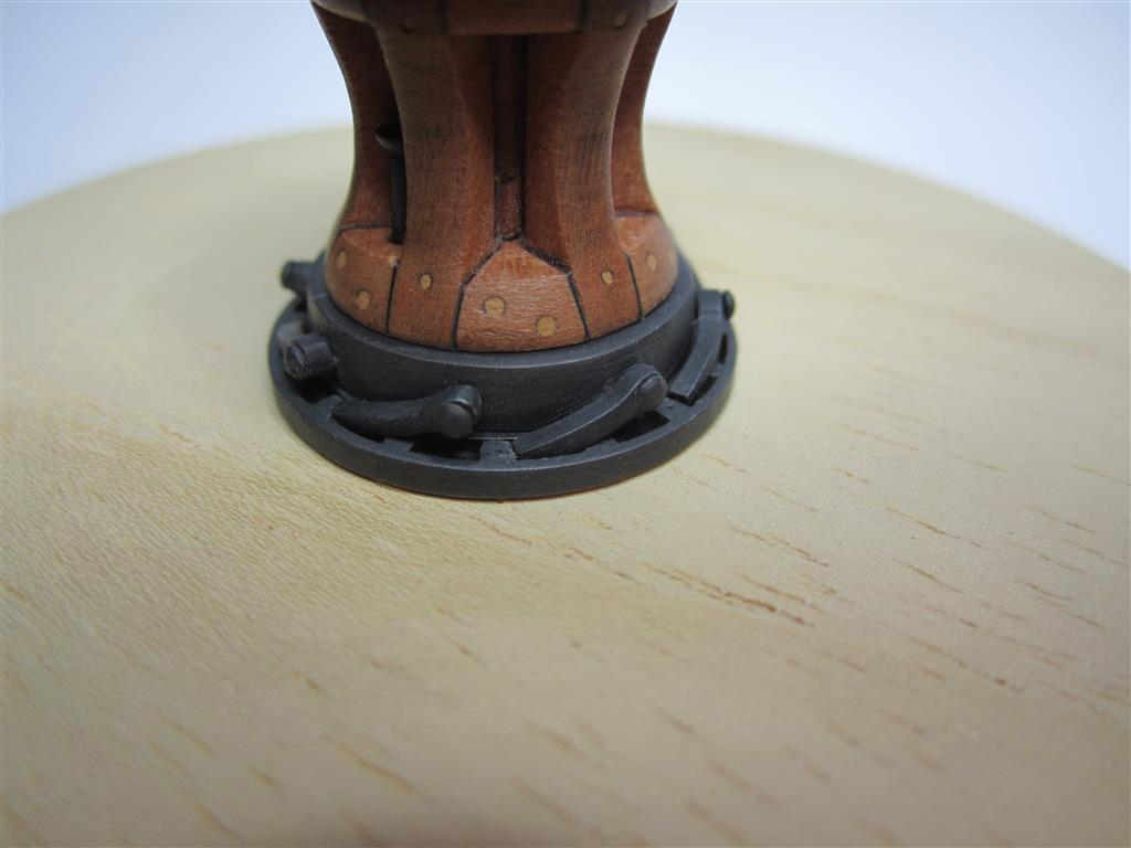
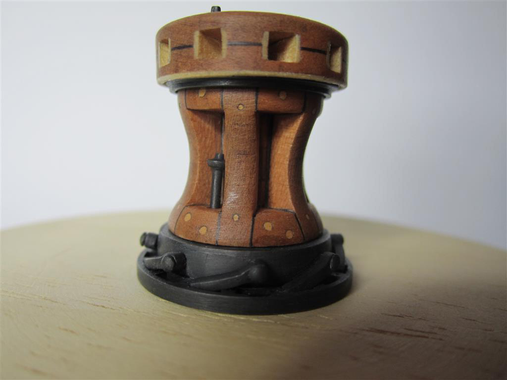
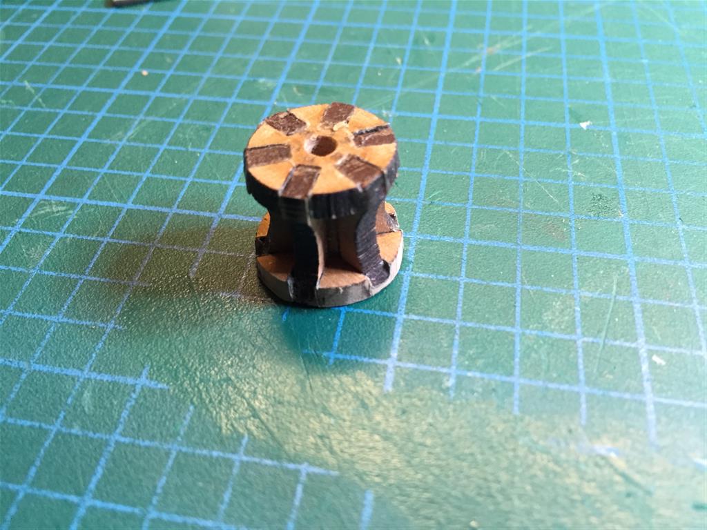
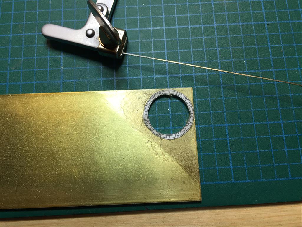
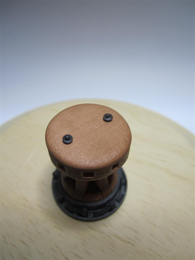
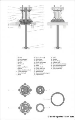
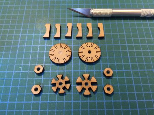
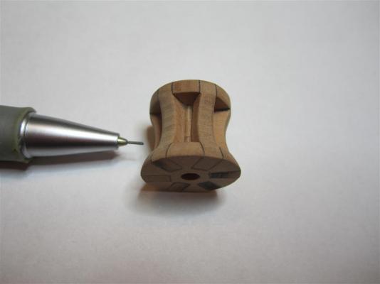
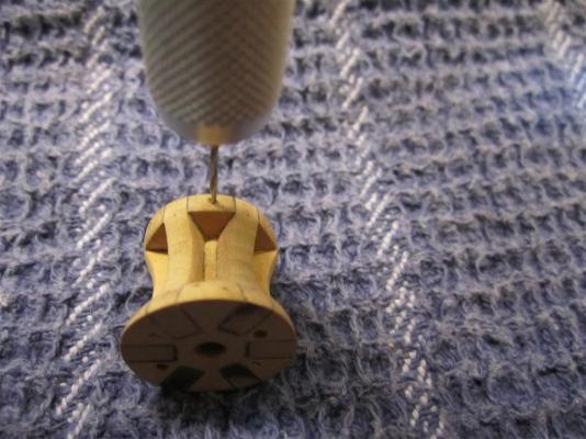
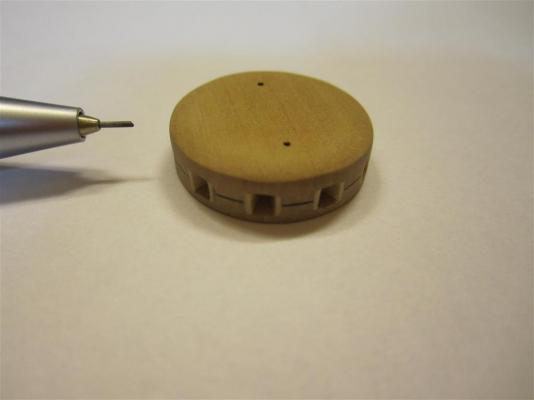
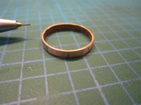
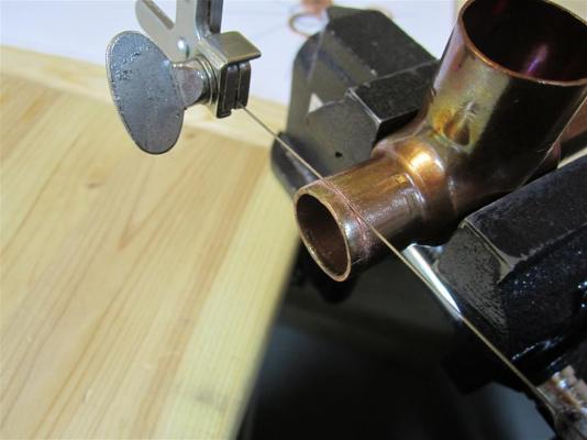
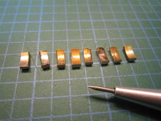
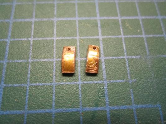
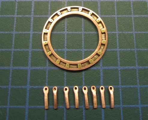
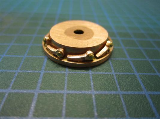
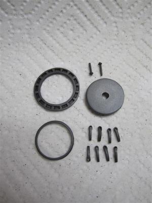
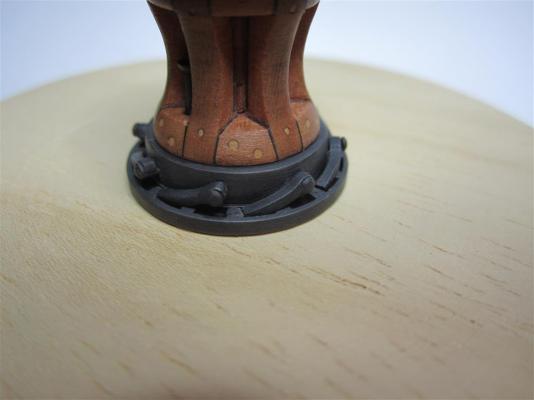
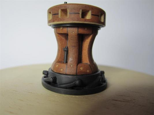
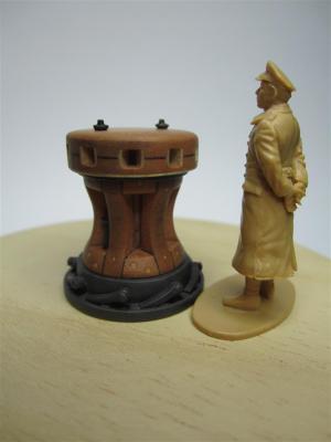
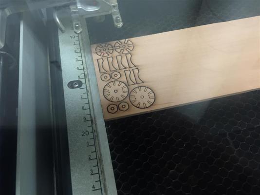
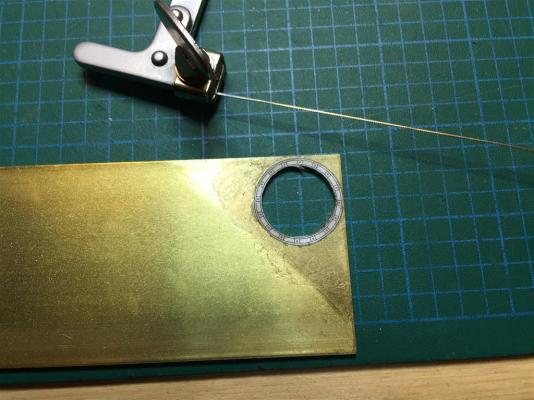
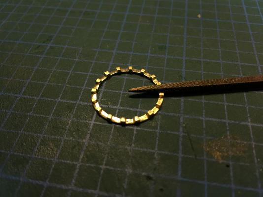
CAPTAIN PHILLIPS’ PATENT CAPSTAN To this point, my build log has included detailed notes about my research into Franklin's ships, and is largely a mirror of my blog, Building HMS Terror. While I know some followers have enjoyed my research notes (thanks for all the kind words of encouragement), others find them tedious, and recreating them here every time I finish a part has become quite time consuming. For the remainder of my build log, I've decided to do something a little different, and keep this primarily as a photo essay of my build. I'll continue to post research notes, but those will only appear on my blog. This change will also allow me to post a few more photos here, for those who want to see more wood and metal. So, with that formality out of the way, here is my attempt to build plans and a model of an 1839 era improved capstan. For those interested in the historical research I conducted, please consult my blog! An 1839 era Phillips, capstan, as I believe it may have been configured for use on HMS Erebus and Terror. Cutting the capstan components on an Epilogue laser cutter. The completed pieces. Vellum was added to enhance the joints of the capstan. The assembled capstan before sanding. Sanded to shape. Drilling the bolt locations. The completed drumhead. Some Phillips' capstan models show lined sockets, so I added boxwood liners. I admit that it was primarily an aesthetic choice. I cut the drumhead plate from an unused pipe fitting which I flared to the right size. I filed a lip into the plate by hand. I cut the pawl rim (ring) out of brass plate using a jeweler's coping saw. I filed each stop by hand, after carefully scoring the brass The pawl rims were each made from pipe fittings flared to the precise diameter. The pawl rim prior to soldering and sanding. The piece following soldering. I used copper solder for the first time on this piece - despite being very dirty, it worked well. To maintain the proper curvature, I cut the pawls from a copper fitting. The pawls cut roughly to length. Bolt holes were drilled before shaping. Each pawl was filed and shaped by hand. The completed pawl rim (ring) and pawls. Two traits unique to Phillips' capstans can be seen here. First, the pawl rim was bolted through each stop, rather than in the spaces. Second, Phillips' capstans had between six and eight pawls, while earlier models typically had four. The pawlhead. The completed pawlhead with the top plate soldered in place. Contemporary models show that the pawlheads on Phillips' capstans were made entirely of iron. Dry fitting the metal pieces. The pawls need some thinning here. Pieces prior to finishing and assembly. Blackening the metal parts. The metal pieces after blackening, buffing, and sealing (I use Krylon matte coat as a sealer). The completed capstan. The wooden pieces have been treated with Minwax wipe-on poly. Detail of the pawl rim and pawls. The drumhead (the drop pins indicate it is in direct-drive mode). Detail of the lower drop pins and drumhead plate (I couldn't find scale chain small enough to model that feature). Mini-Crozier inspects his capstan, recalling his good times with Parry.


- 346 replies
-
- 36
-
-
- terror
- polar exploration
- (and 2 more)
-
Druxey is absolutely correct here. 8:1 or even 10:1 and a longer soak gives the best finish with blackening agents.
-
What an inspiration! Just superb.
-
Hi Druxey, I appreciate the kind words (and thanks everyone for the likes). This is very good advice. I checked this morning under good light and so far so good. Given how slowly I build, I've been really worried about oxidation, almost to the point of paranoia. I keep all my wood (including the model) under the cover of a dark blanket when I'm not working on it (this despite the fact that I work in a dark basement). I've read that UV light is a prime factor in oxidation, while heat and moisture are secondary issues. I also control the latter two, and I have the electricity bills to prove it! But again, this is good advice. Once the filling blocks are installed and I start fairing the bulkheads it shouldn't be an issue. Hopefully that will be done very soon.
- 346 replies
-
- 3
-
-
- terror
- polar exploration
- (and 2 more)
-
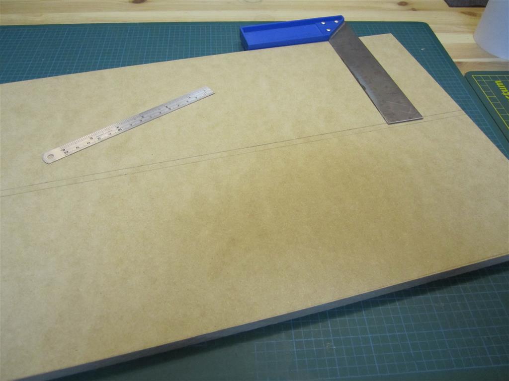
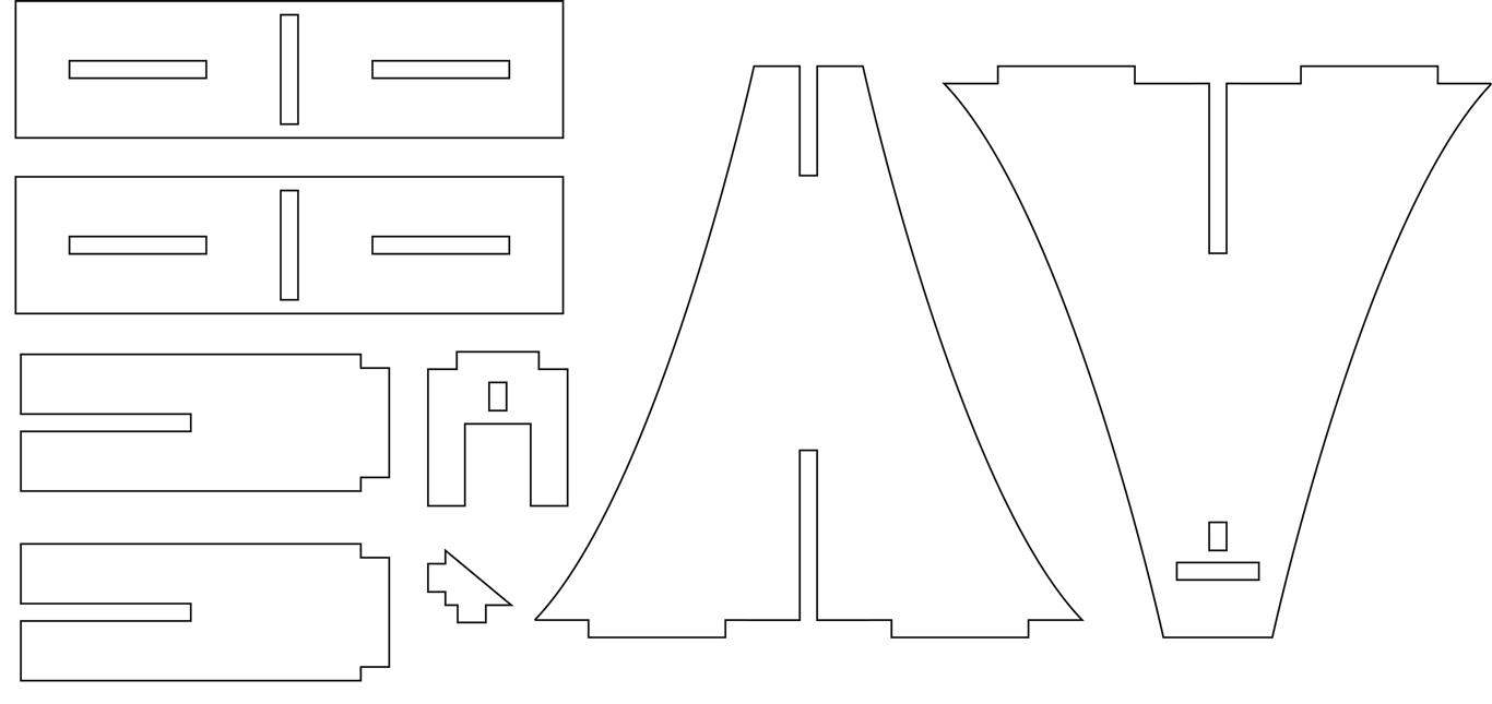
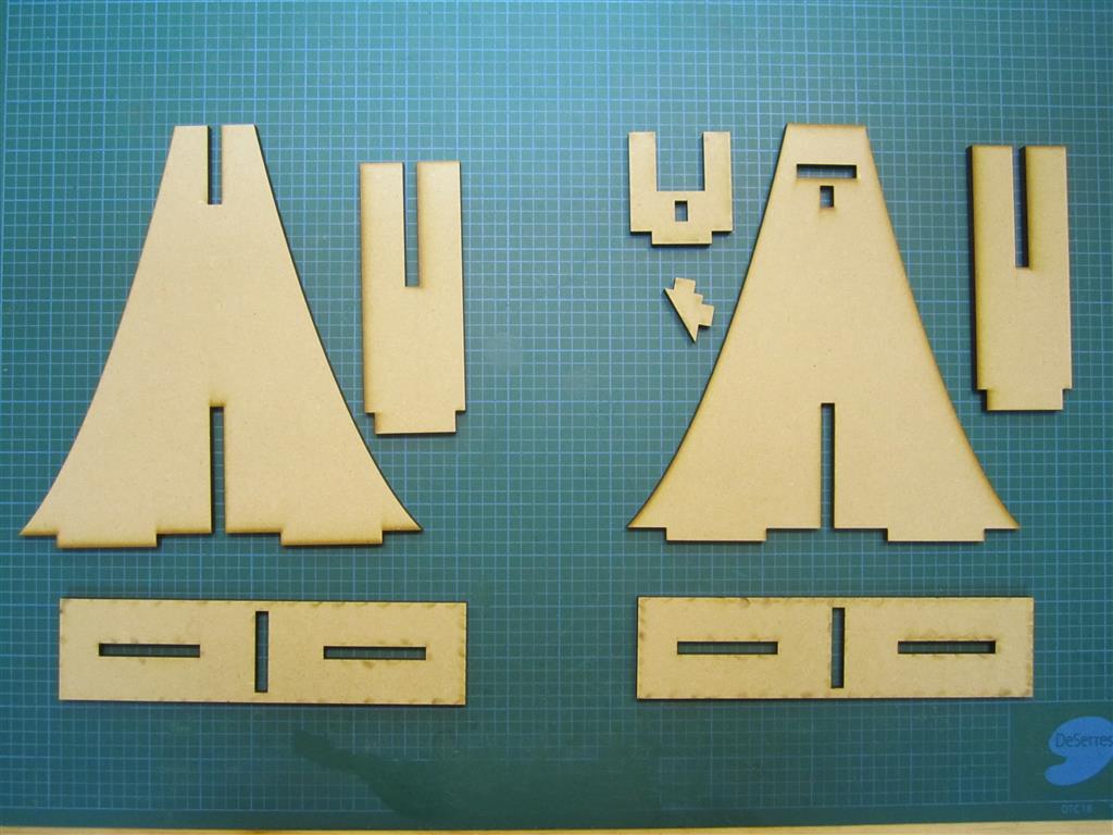
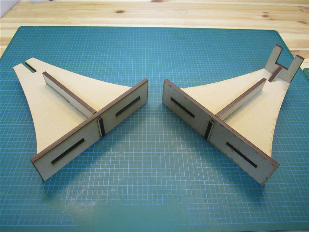
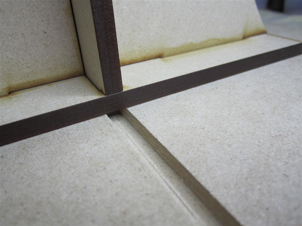
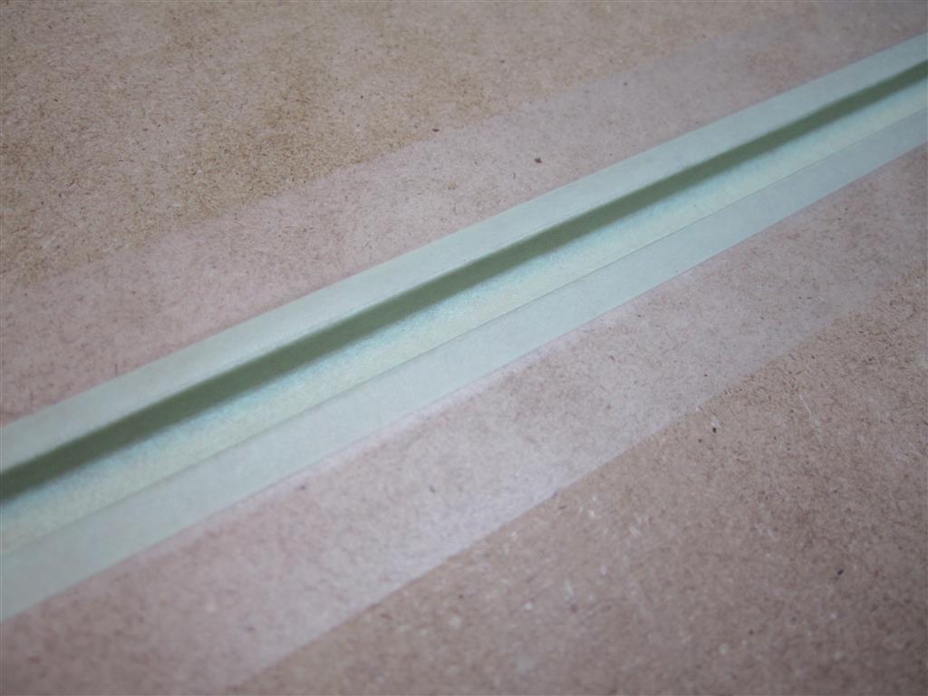
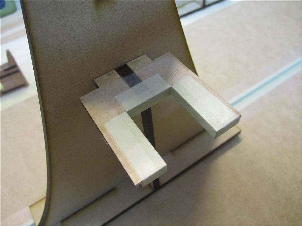
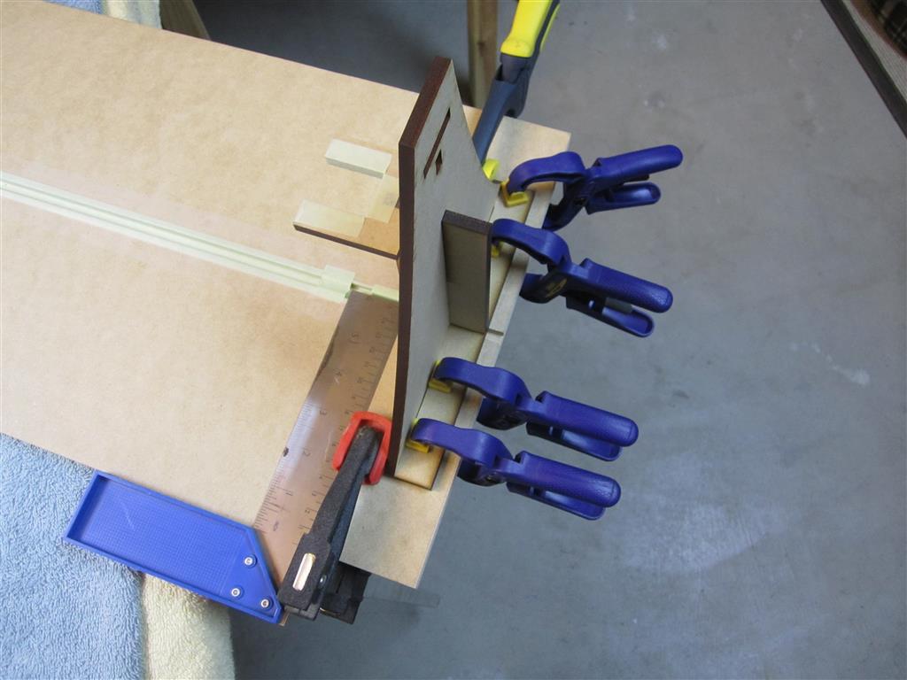
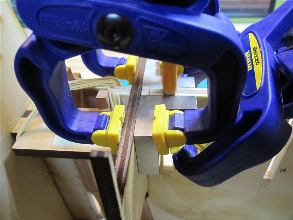
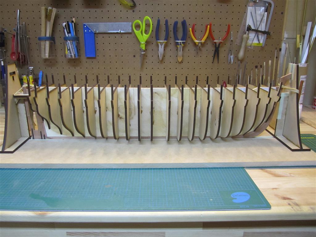
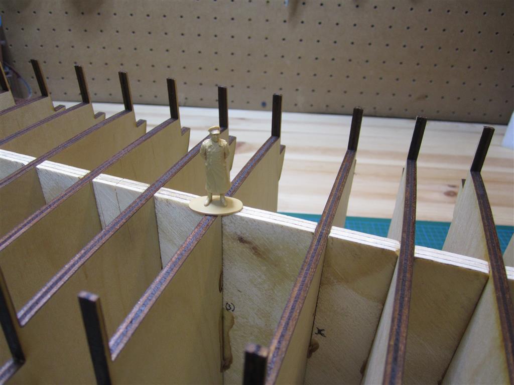
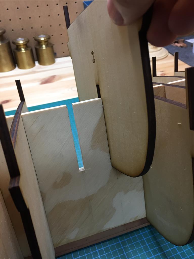
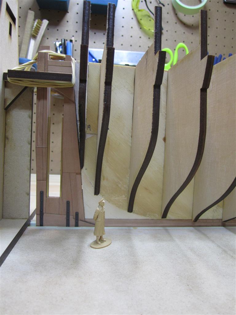
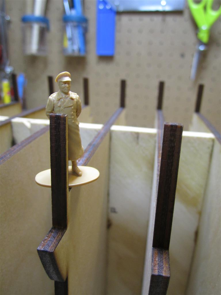
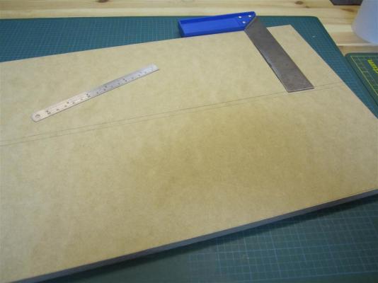
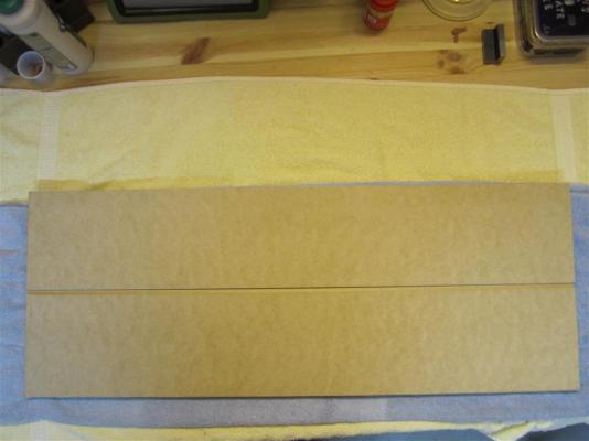
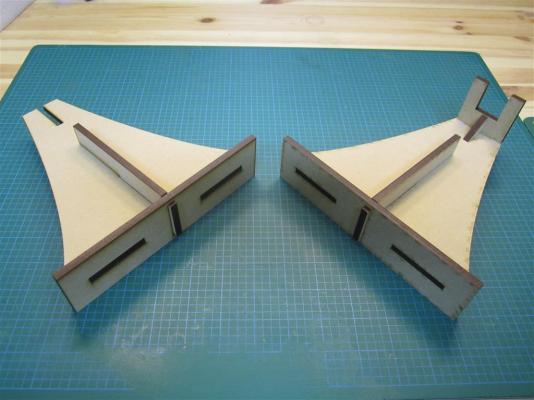
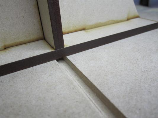
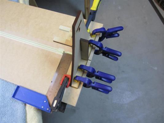
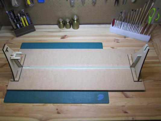
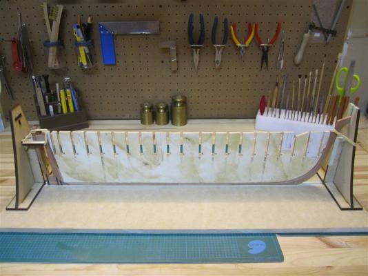
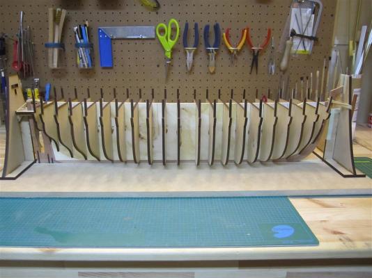
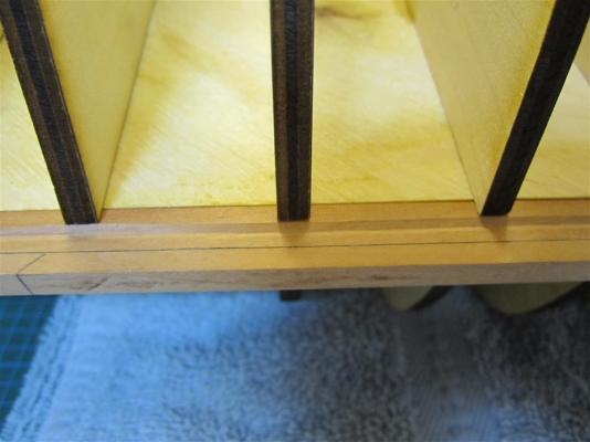
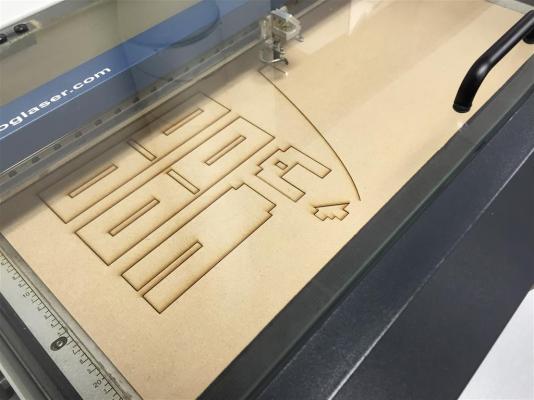
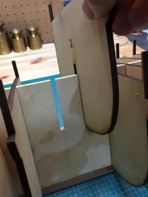
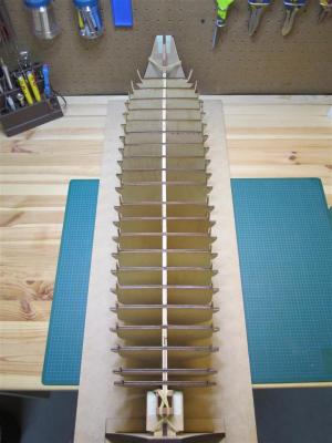
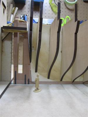
BUILDING A BOARD My most recent sub-project has involved constructing a “building board,” essential for accurately aligning the bulkheads with the false keel of my model. The board needs to keep the false keel perfectly straight and perpendicular, while providing a flat surface for gluing the bulkheads at right angles to the keel. I started the board by cutting a 1/4“ groove into a 32" long piece of MDF sheet. The groove is just slightly deeper than the false keel on the model, providing a full view of the rabbet, and fits tightly so that the keel remains perfectly straight. Marking the groove on the MDF sheet. The board is 12" x 32 ". I cut the groove into the board with a table saw. MDF is brittle, so care is needed at this stage. The stern and stem of the model also needed to be kept perpendicular to the board. To achieve this, I designed two supports, one for the stern and one for the stem, which would slot into the building board groove. I used a laser cutter to make these from 1/4” MDF sheet; they fit together somewhat like a piece of Ikea furniture. My custom plans for the stem and stern supports. The idea for the interlocking pieces came from children's toys. Cutting the pieces from 1/4 " MDF. My local library provides a 60 watt laser cutter for public use. The pieces after cutting. The finished supports (stem on left, stern on right). It's hard to see, but the support has a rail designed to fit into the groove for proper alignment. The supports were glued into place, and their alignment was double-checked with a square. I lined the groove with painter's masking tape to prevent damage to the model's keel. I lined the supports with masking tape as well. The finished building board. Instead of using set screws, which might damage the model, I used rubber bands to secure the model in place. In practice, the fit was tight enough that rubber bands weren't really necessary. The bulkheads fit tightly and relatively squarely, but it was necessary to use a carpenter's square to ensure that they were at perfect right angles to the keel. These stainless steel squares from Lee Valley were perfect for the task. The second-to-last last bulkhead is put in place. The completed superstructure. It's hard to see here, but two of the forward stations have alignment issues at the area of the chock channels and bulwarks and will need to be sanded and/or modified with trim. I double checked the plans, and the errors, around 1.5 mm off, seem to have crept in from my original measurements. These errors weren't large enough to force me to re-cut the stations. I'm quite happy with the alignment (the stern looks slightly twisted here, but it's just a trick caused by the camera angle). Midships bulkheads at the position of the rabbet. A view of the bottom of the ship. Again, I'm quite pleased with the alignment (the stem and stern are still little wobbly and will need some filling blocks). Mini-Crozer stands on his deck. It's been a long time. Mini-Crozier inspects the stern, noting that work is needed on the bearding line. Though Terror was small by Royal Navy standards, a 102 foot ship was still a substantial vessel, as this image indicates. Mini-Crozier stands at the Captain's sacred spot on the quarterdeck. Now that the bulkhead of the model is finally assembled, I can move towards planking it. A significant amount of fairing is necessary, and I hope to finish that shortly. Meanwhile, I've almost completed the "Phillips' Patent Capstan", and I hope to reveal my plans and model here soon. P.S. If you are interested in some new cabin accommodation plans for the lower deck, please see my blog (in my signature).


- 346 replies
-
- 18
-
-
- terror
- polar exploration
- (and 2 more)
-
Not at all Antony, thanks for the information! I actually consulted with the special effects company who worked on the documentary. They wanted their ships to be accurate...I hope this version has more views of the wreck.
- 346 replies
-
- 4
-
-
- terror
- polar exploration
- (and 2 more)
-
Hi Richard, That's not a bad idea! E&T
-
Druxey, Mark, and Antony, Sincere thanks for the comments and to everyone who pressed "like". It was a real honour to work on their stamp. But now that this is out I can turn back to glue and sawdust!
-
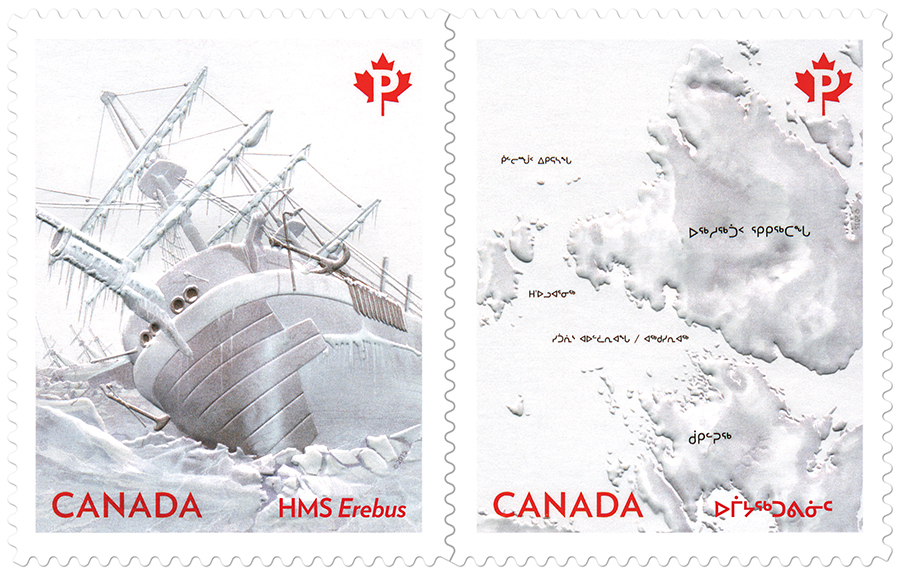
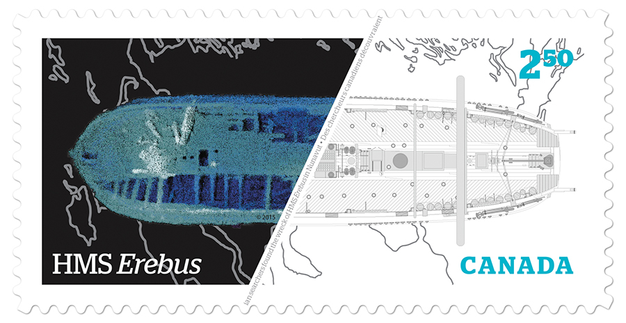
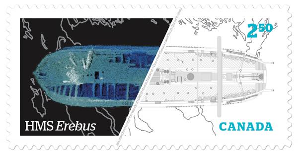
CANADA POST’S NEW EREBUS STAMP Several months ago I mentioned on my blog that I was working on several side projects related to HMS Terror. Today, Canada Post unveiled a series of new stamps commemorating the Franklin Expedition and the 2014 discovery of HMS Erebus. The stamps include a permanent se-tenant issue and an international-rate stamp, and I was fortunate enough to have been asked to contribute an historically accurate plan to their design of the international-rate stamp. I also provided comments and feedback on the ship depicted in the se-tenant stamp. The international-rate stamp showing the sonar image combined with the upper deck plans. Image courtesy of Canada Post, used with permission. The international-rate stamp combines a modern sonar image with an upper deck plan of HMS Erebus that I created. The complete upper deck plan is featured on an uncut press sheet and I also produced a cross-section of Erebus that will be included in packaging materials. The deck plan shows HMS Erebus in her 1845 configuration, which no contemporary plan depicts. This new plan is based on ones I created for HMS Terror, which I carefully modified to accurately match the dimensions, fittings, and features of HMS Erebus. The permanent se-tenant showing Erebus trapped in ice. Image courtesy of Canada Post, used with permission. When I started creating plans of Franklin’s ships, I never expected that they would be seen by anyone but hobbyists and Franklin enthusiasts. I couldn’t have guessed that they might be used in a project such as this – especially juxtaposed with a real image of HMS Erebus. I was shocked at how accurately the plans matched the sonar image, which exposes much about the technology used on the search and the accuracy of the historical source materials relating to Erebus. It was a thrill to work with the talented designers and professionals from Canada Post, and I’m very pleased with the result.

- 346 replies
-
- 15
-
-
- terror
- polar exploration
- (and 2 more)
-
I can't get over the scale of this project. How much does it weigh? Beautiful work, and excellent choice of woods.
-
Thanks everyone for the comments and likes; they are a great source of encouragement.
-
Druxey, sincere thanks for your kind words. Actually that makes me feel much better - I dislike "guesstimating" intensely, but at some point you just have to move on.
- 346 replies
-
- 2
-
-
- terror
- polar exploration
- (and 2 more)
-
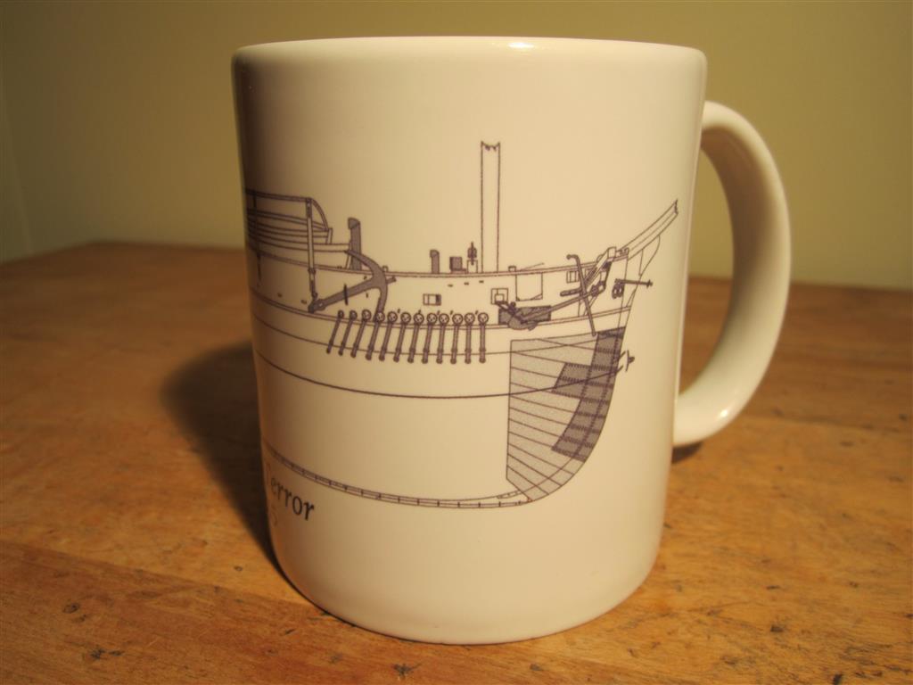
Also, if you like to drink coffee, and like free stuff, you might want to check out my blog.

- 346 replies
-
- 9
-
-
- terror
- polar exploration
- (and 2 more)
-
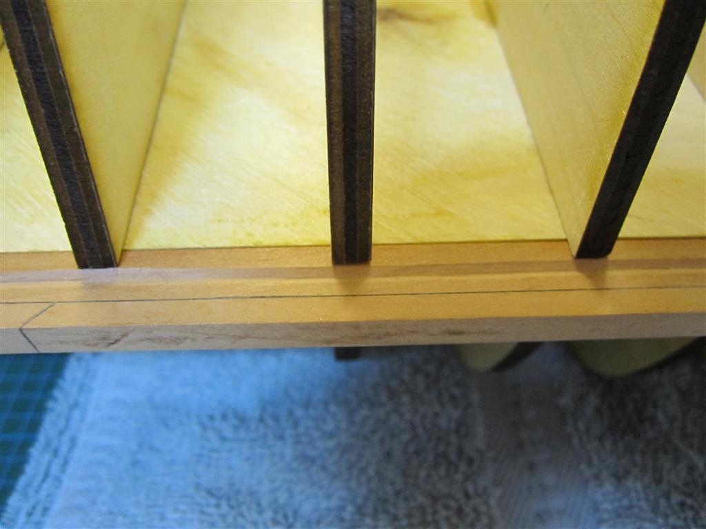
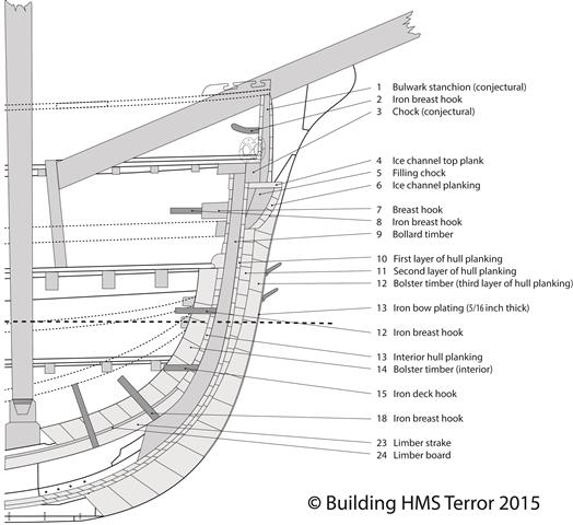
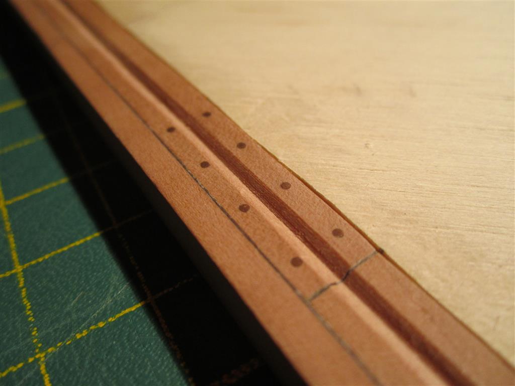
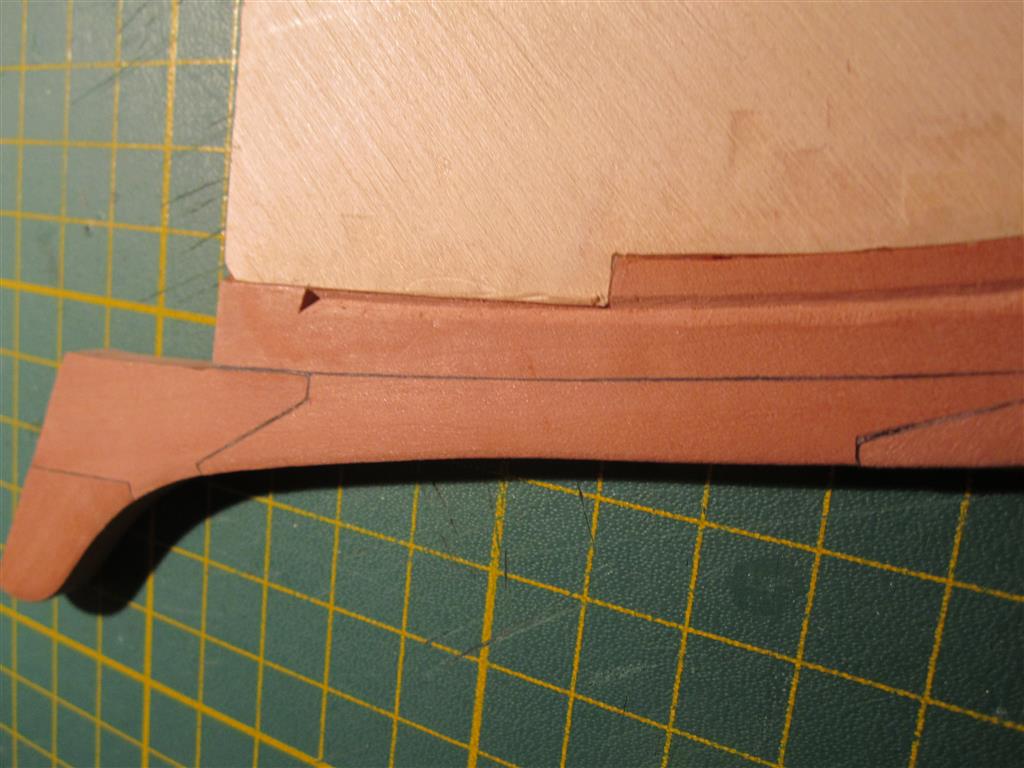
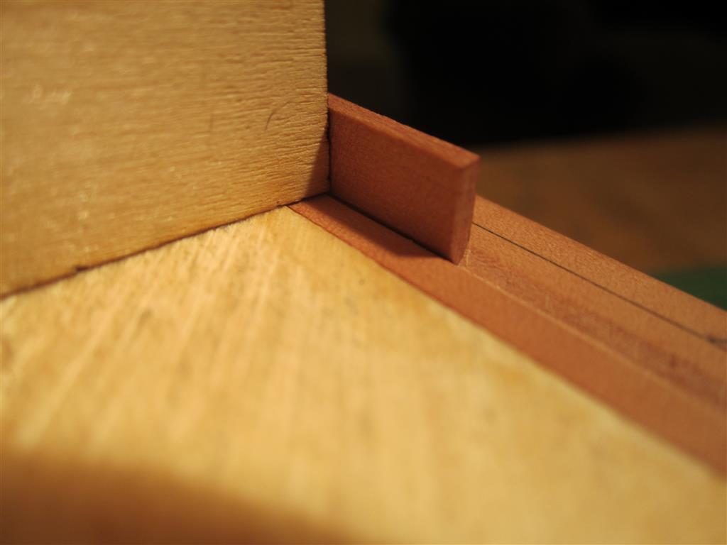
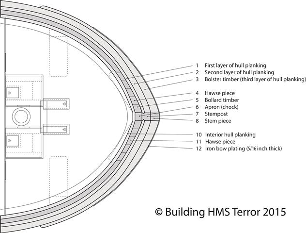
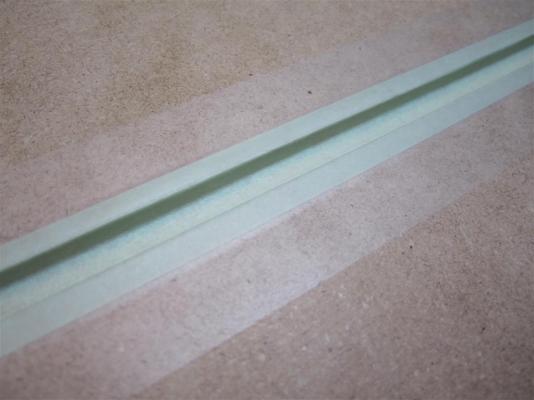
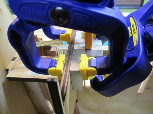
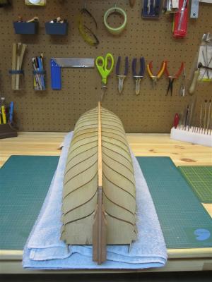
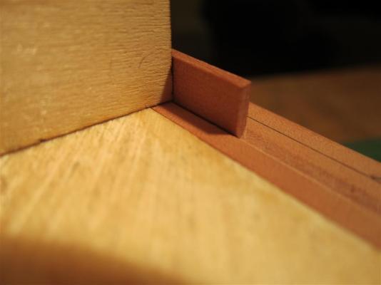
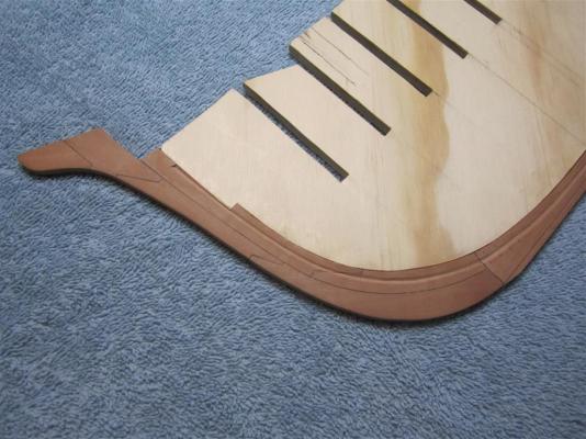
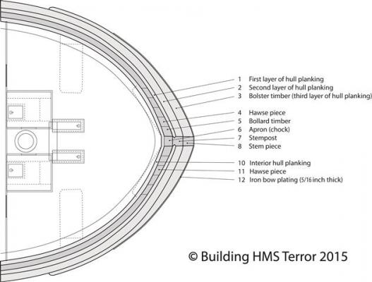
Pulling a Rabbet from Terror’s Hat Last month, I finished the most angst-ridden part of my project to date - cutting the rabbets into my model's keel and stem. My trepidation was rooted in the fact that the rabbet position isn’t shown in Terror’s 1836 draughts [1] (the 1839 draughts [2] only show the rabbet position for Erebus). Normally this wouldn’t be an issue, as Terror’s 1812 [3] profile plan clearly shows the position of the rabbet. However, the 1836 plans show that Terror’s bow, and in particular her upper deck and bulwarks, were extended forward approximately 12.5 inches (why this was necessary is still a mystery to me). This implied that her rabbet position must have been moved forward as well, to accommodate a smooth run of planking along the bow. The rabbet carved into the model’s keel. Like the merchant ships which were the basis for Terror’s design, the 1812 draught shows the rabbet was taken out of the centre of the keel (incidentally, this position probably contributed to her poor sailing qualities). I had originally assumed that Terror’s cant frames, hawse pieces, and bollard timbers may have been modified to accommodate this lengthening of the deck. This wasn’t an unwarranted assumption, because Terror’s 1836 profile plan shows that Terror’s upper stem piece was extensively remodeled, suggesting a significant refit of the bow timbers. However, after further consideration, I’ve come to the conclusion that such extensive modifications were very unlikely. We know that Terror’s original top-timbers and bulwarks were entirely levelled when she was caught in a hurricane near Lisbon in 1828 [4]. This means that replacement bulwark stanchions needed to be installed when the ship was repaired. The upper deck may have been expanded at this time, but I suspect this occurred in the 1836 refit as the solid chock channels provided an opportunity (and platform) to most effectively hide this shift forward. In either case, because her bulwarks had been levelled, the modifications could have been made without extensive reworking of the bow timbers. Therefore, my solution is to leave the rabbet position precisely as shown in Terror’s original 1812 draughts and to rely on modified bulwark stanchions to account for the lengthened deck. This permits me to move forward with the project with the least amount of conjecture, because the only speculation I need to make is about the construction of the most forward bulwark stanchions. The port stem rabbet. Another view of the rabbet - Terror had a very bluff bow, but the rabbet "opens" slightly in this area. A dummy section of planking, dry-fitted into the rabbet to test how it fits with one of the station bulkheads Settling on a final position of the rabbet allows me to finally assemble the bulkheads and begin planking the model. This decision also permitted me to finally draft a plan of Terror’s complete bow architecture. Profile of the Terror’s bow architecture, showing the manner the bow was strengthened for polar exploration service. To accommodate the lengthening of the deck, I added a conjectural 12 inch chock fayed to the fore edge of the bollard timbers and cant frames, against which the bulwark stanchions would have been bolted. Plan of Terror’s lower deck, detailing the layers of planking and metal sheathing added to the ship. The plans expose the effort the Admiralty placed on strengthening the ship’s bow at the waterline. More than 55 inches (4.5 feet) of iron reinforced oak separated the stores on Terror’s orlop deck from the water. Near the foremast step, that distance multiplied to nearly 12 linear feet. James Clark Ross [5] tested these reinforcements in a most daring fashion during his Antarctic Expedition. By January 5th, 1841, Ross had spotted what he thought was open water south of the Ross Sea but found his way to it blocked by a ring of thick pack ice. Confident in his ships, he sailed along the barrier until he saw a “favourable point” and, under sail, rammed the Erebus and Terror into it for an hour, eventually fracturing the ice and punching his way through. He discovered the Ross Ice Shelf six days later. Footnotes: [1] National Maritime Museum Object ID: ZAZ5672, ZAZ5663 [2] National Maritime Museum Object ID: ZAZ5673 [3] National Maritime Museum Object ID: ZAZ5615 [4] 1835. Narrative of the Wreck of H.M.S. Terror. United Service Journal and Naval and Military Magazine 1. Pages 229-236.


- 346 replies
-
- 9
-
-
- terror
- polar exploration
- (and 2 more)
-
Thanks for your review, Mark. I'm lucky enough to regularly use a 60 watt Epilogue laser cutter available for use at a local library. The unit is consistently maintained and adjusted by professionals and I still have issues with it. The best advice I can give is to use a test cut or two every time you use the machine, even if you are cutting the same materials and thickness. I usually just cut a 3mm strip off the edge of the material I'm cutting, and this helps me calibrate the speed, power, and ppi. With the 60 watt machine, setting the correct speed and power is critical, and on everything I've cut, including 1/4 plywood, I've had to keep the speed and power quite low to avoid charring (10 or 20 speed, 35 - 40 power). I keep a logbook of settings for every cut I make, recording the different materials and thicknesses, and this helps me avoid too much waste. But I find the most critical step is the test cut - it's saved me a lot of ruined material. The mirrors and tubes in these machines constantly shift and degrade, and even planks from the same piece of wood have slightly different densities, so you never have the same cut twice, even with a professional quality machine. I cut some stern timbers on swiss pear last week - which reminds me that I'm behind in my posts!
-
Yes indeed it is Druxey, thanks for the post. In February I had a beer at a pub, now called the "Sir John Franklin", in Greenhithe, the very establishment the officers rented the day before they set sail. The quay where the ships were moored still exists just behind the pub, and the cobble stones leading up to it are the same stones Franklin, Crozier, and their men would have walked over to board the ships. Unfortunately the rooms where they slept weren't accessible. It's a must-see for anyone interested in Franklin and beer. https://m.facebook.com/pages/Sir-John-Franklin/110532939006680?id=110532939006680&refsrc=https%3A%2F%2Fwww.facebook.com%2Fpages%2FSir-John-Franklin%2F110532939006680
- 346 replies
-
- 4
-
-
- terror
- polar exploration
- (and 2 more)