

.jpg.f26acc9a74319261612561bfa7da1303.jpg)
vaddoc
-
Posts
1,605 -
Joined
-
Last visited
Content Type
Profiles
Forums
Gallery
Events
Everything posted by vaddoc
-
.thumb.jpg.6fd4c1b78768bb3efd745ab810936005.jpg) Wonderful photos, makes you want to get in and set off! I very much like your choice of wood as well.
Wonderful photos, makes you want to get in and set off! I very much like your choice of wood as well. -
Exploring FreeCAD for ship modeling
vaddoc replied to TonyM's topic in CAD and 3D Modelling/Drafting Plans with Software
I think Phil is right. The way I would do this is this: First define the sheer and rabet lines in half hull and bring them out to the half width of the hull. Design the transom. These will never change and they are the starting and finishing point of all other lines. They are essentially the borders of the planking. They need to be fair so a "Fair" function needs to be given by CAD. Use as few points as possible Then insert the waterlines, buttocks and diagonals. They need to be fair as well. Then draw the frames in every station. Study every frame as it meets the various lines and the lines that are wrong will be easily identified. Correct and fair these lines, then draw the frames again and fair. Just one or two cycles will be needed, after that the accuracy of the plans will be way more what hands can achieve cutting the wood. Starting directly with the frames as given is I think more difficult Vaddoc -
Exploring FreeCAD for ship modeling
vaddoc replied to TonyM's topic in CAD and 3D Modelling/Drafting Plans with Software
I have no experience with this CAD but it will be much easier to work on the half hull and then mirror to create the other half. Also may be helpful to define rabet at keel, stem, sternpost and Transom as this will be the starting and finishing point of all your waterlines and diagonals etc., this should be fair as well. (Provided lines are to outside of planking which is not always the case) I think first built keel, stem and stern and then add the lines and start lofting. Will the width of keel, sternpost and stem be constant? -
I think such info can be found in "The construction and fitting of the English man of war.1650-1850" by Peter Goodwin. He seems to have studied all the dimensions and the rules they used back then. The book is full of numbers and calculations!
-
Which wood filler to use
vaddoc replied to dkuzminov's topic in Building, Framing, Planking and plating a ships hull and deck
Not really, it just shows when it is dry to sand. I ve succesfully mixed Elmers with acrylic paint. I suspect the purple, essentially colourless filler, can be mixed with wood dust for a near perfect colour match but this I have not tried this yet. -
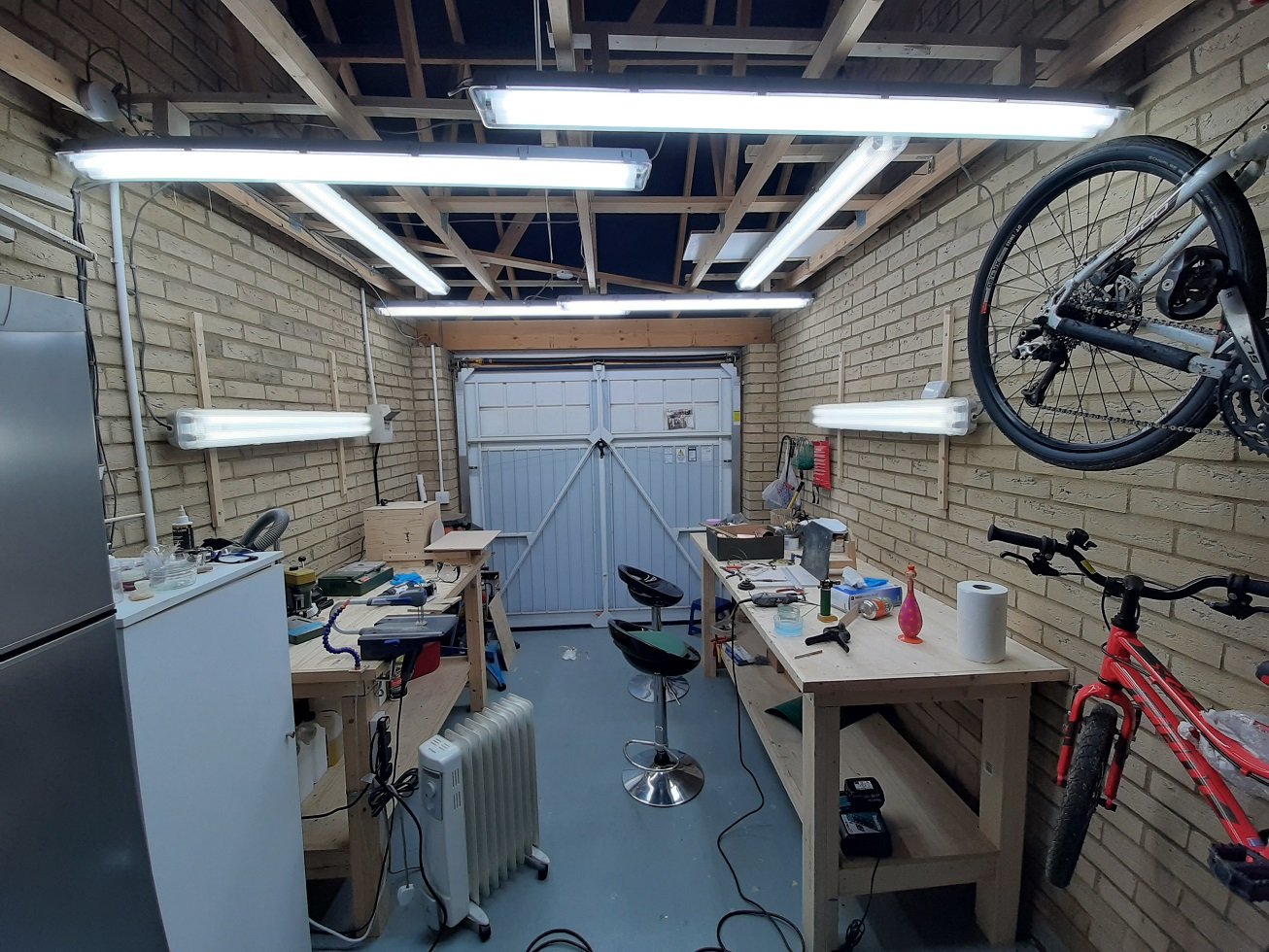
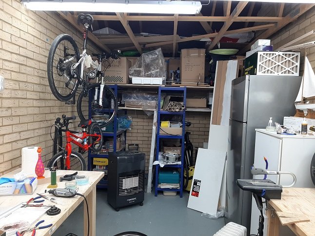
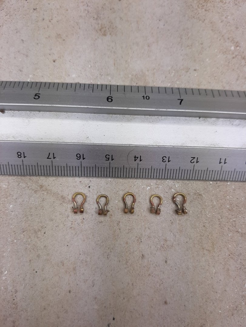
Well, it has been a very long time since I posted anything but I really did not have any time to work in the garage. Today though, I spent an hour or so, trying mostly to find where I last left things 2 months ago... First, I sharpened my chisels which were in a bit of a state. I watched Paul Seller's video again and decided to fully adopt his free hand method. Indeed, my chisels are razor sharp now but the bevel is quite convex. I also added 2 Ashley Iles chisels to my wish list (near the top), a 3 mm single bevel and a 3 mm V chisel. Next, I changed the sand paper and the work top on my home made disc sander. I also took a picture of the new garage set up. I rearranged the shelving units and the storage space increased massively. Most importantly though, I more than doubled the lighting. I now have almost 1000W of fluorescent tubes concentrated in an area 3 x 3 m. It is bright but I feel it could take another 50% increase! You might be able to pick out the Deben sitting unloved in a shelf... Then I sat down to do some actual work and made 5 shackles. It took a bit of effort to actually settle into a rhythm and had 3 failures. Another kind of shocking discovery is that I have developed significant presbyopia. I had realised this when I visited my optician this summer but I thought I could delay things a bit. Well, this is not the case any longer, I simply cannot do any kind of detailed work! I ordered some cheap reading glasses from Amazon until I see my optician this summer for a better solution, undoubtedly far more expensive.

-
Which wood filler to use
vaddoc replied to dkuzminov's topic in Building, Framing, Planking and plating a ships hull and deck
After trying lots of fillers, I also now use Elmers colour changing filler. Dries quickly, sands nicely. Lovely staff. -
Great progress GL, you tackled reasonably big projects like mast tapering, sheave and cleat making and mast hardware with ease. I am looking forward for the rest of the journey! Is your rope bought or homemade? Vaddoc
-
Welcome Emmet! Have fun building your first model, it will be interesting to see how your mobile workshop will work. Vaddoc
-
Gaetan, it is difficult to fully perceive the depth and beauty of your work. I seriously doubt that the actual ship was as well built! A great pleasure to visit you logs. Vaddoc
-
Lovely work Michael and very inspiring! Did not know that shim sizes of brass sheet existed. Great work on the hinges, I now regret missing the opportunity of making working hatches and companionway for the Deben.
-
Gary, I just finished catching up with your log. Not only you are creating a wonderful model, you are clearly having lots of fun! Now, your boat is a source of inspiration but one issue I ve always had was the colour and texture of the masts. Strangely, it never occurred to me to paint the masts with acrylics. I do not have your skills in mixing paint but this is definitely something to try in the future.
-
Many thanks to all for your input! Gary, I agree, pear is lovely. The problem I always had is that due to the pink-ish colour it seems to only combine with ...pear. But I am looking into your suggestion. GL, I indeed remember our discussion very well and I am following your logs (not as often as I would like due to life pressures). The yawl however has a much more rounded bow and I really doubt that 2 mm steamed pear will be convinced to follow this curve, even steamed, without fracturing. Also, I guess the planks will need to be cut over a pattern with a knife to come out with a fair curve and pear is very hard. Still, I ll give it a try. Michael, how right you are. I just received a copy of "Boatbuilding" by Chapelle. What a lovely book it is! It describes how the various types of boats are built and how lofting is done with a pencil and ruler. This book is all about the 80/20 rule and finding the golden balance between being well prepared and having done a good lofting but also at some point start building the boat knowing you can correct miss-matches by taking more or less material. Today's CAD accuracy is a completely alien concept to Chapelle. There is actually a point where he advises, if the frame cannot be bent into place, "just use a shim"! I must say that in previous boats, the planking would actually correct design issues as the wood would want to find its natural fair position-then just had to be framed into place. Back to the boat, I have finished designing all the temporary frames as well as the building jig. This will be a really big boy! I have also placed a rather large wood order but ordered only samples for the wood planking. Not sure how the admiral is going to take it but she is busy getting new floor and carpets so maybe the timing is favourable. I ll post new photos once the wood is in Regards Vaddoc
-
Welcome Peter! This boat can certainly be repaired, repainted and re-rigged. Then you might be tempted to take on a new maybe more challenging project. Regards Vaddoc
-
Welcome VM! Have great fun building your boat but do start a log as well!
-
Rick, Valejo model colour range is for brush painting but make sure you use their own thinner (not the air brush thinner). Do not use homemade one. Also use a bit of their retarder. Combine with system 3 brushes and you can successfully repaint the Capela sixtina!
-
Valejo paint is great. I use the hand brush range and it is fantastic. Humbol enamel are great as well but water based paints are just too easy to use. Try decoart (americana) sealer, cheap and very nice. Dries in 15 min. Make wood dust as soon as possible, rest will come. Welcome back! Vaddoc
-
Tried a few wood fillers both modelling and trade (avoid), wood dust with PVA, even silicon as filler. Best by far is Elmers. Nothing stops you mixing it with wood dust or acrylic paint. https://www.amazon.com/Elmers-Carpenters-Change-Filler-E917/dp/B00JKB2GP2
-
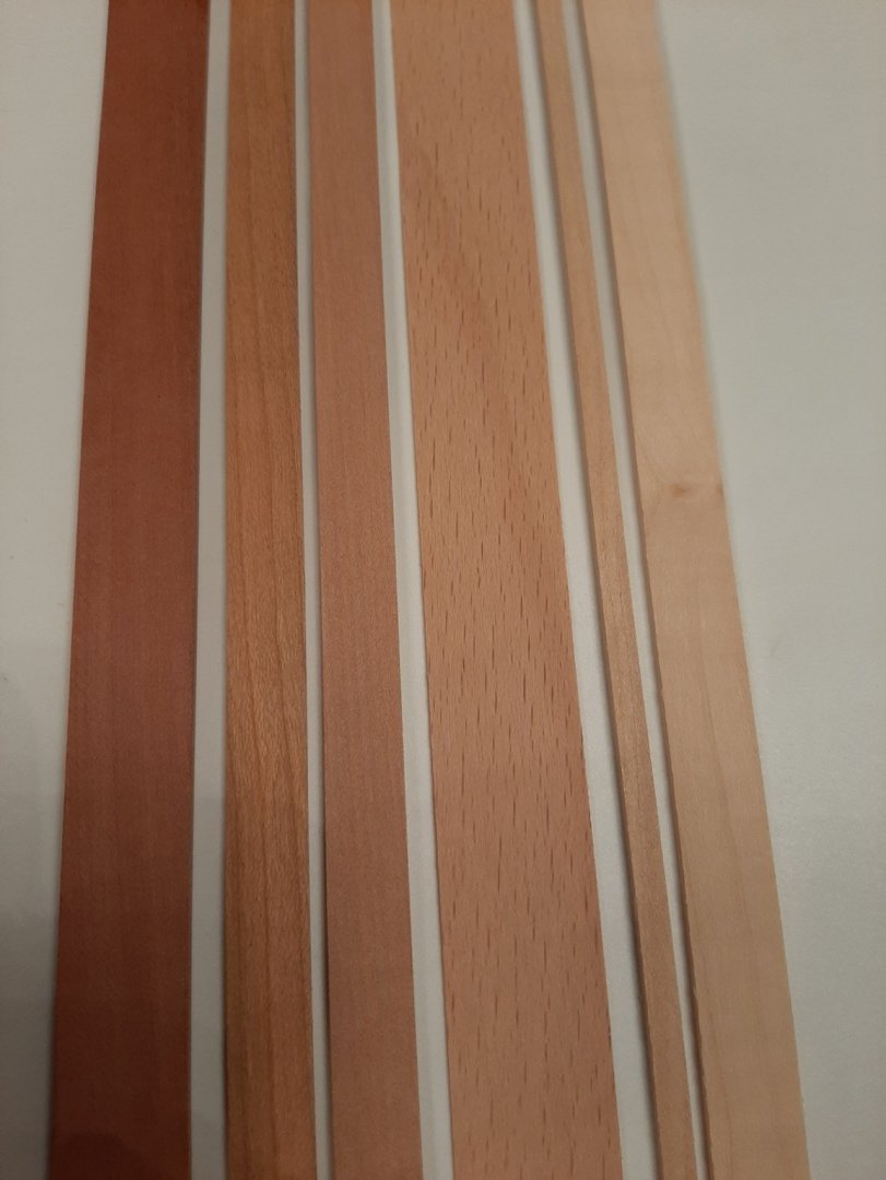
Actually, let's just discuss it here. I plan to order wood from Massiv Holz (EDIT: It was actually Arkowood) in Germany, I have bought a lot of wood in the past and it was good quality. They have a wide range of woods, some of which I know and some not. The minimum number per size is 10 strips and also, I think I will need maybe 15 pieces 100 x 1000 mm sheets for the planking so overall quite a lot of (expensive) wood. Some woods are much more expensive than others. The way I see it, there are 3 main groups of components. The planks, the ribs and all the rest. All will be left unpainted. The curvature of the planking mainly near the bow I think is too extreme and probably needs a wood that has excellent steam bending properties. Similarly, some of the ribs will need to bend quite a lot. This means that pear and cherry probably cannot be used (or can they?). They do not respond that well to steam bending and can be brittle, especially pear. On the other hand, birch, beech and maple will take any curve with no issues, holly and ash as well. For the hull and other pieces, anything can be used. However, I would like dark colours and birch, maple and holly (and hornbeam which I liked) are very white. In the next photo there are 6 woods that I could use. From left to right they are dark swiss pear, cherry, light pear, beech, birch and maple. The birch and maple are actually a bit paler in real life than in the photo. The only combination I can think is beech for planking and the ribs and pear or cherry for the hull. Any suggestions on wood species, bending potential and colour combination would be very welcome. Regards Vaddoc
-
Indeed Druxey. I read they were purposely forcing the growing trees to become crooked so they had a supply of such timbers. Now, I am slowly finishing the drawings by arranging the temporary frames but I really would like this boat to look good and I need to decide what wood to use. I would like to ask your help in choosing wood but maybe best to create a new thread, your contribution would be greatly appreciated. Vaddoc
-
Thanks GL Indeed, I was unsuccessful in getting the shapes of the planks with CAD. It will be much easier on the actual model with battens and paper shapes. It is possible though that the planks will have a very odd shape and significant curvature. Of course 50 or 60 cm wide pieces of timber are not really realistic, this is why I think the planks for these boats may have been scarfed which reduces the width of the blanks to half. Back in the 18th and 19th century they were building similar boats but up to 40 ft long, these had to have scarfed planks. Vaddoc
-
Wonderful drawings! I like the a4 box trick. In the past I struggled lining up both faces of the frame, this seems to have worked fine I ll be following from the back rows GL Vaddoc
-
Dear all Life is so busy that I do not have any time to work on the Deben. This is likely to be the case for the next months and probably even years. Regrettably I am also struggling to keep up with the numerous logs I have been following. Still, I have been stealing some moments mostly at night, in between the girls' bath time and sleep time to work on the yawl. The results were mostly disappointing but I got to understand planking and boat building in general much better. I really wanted to get the planking done on CAD but this proved immensely difficult. I spent many evenings but I could not get it to work. It certainly will be much easier in the actual model with a few battens! I am posting some screenshots of the multiple attempts I did, trying many different ways. Some photos look great but really are not. I think the garboard is pretty close but all other planks are likely to end up with very strange shapes. This boat has a very round bow and I think this adds complexity to the planking process. It is probable that this boat absolutely would need scarfing to get the plank shape. For some reason I have a childish optimism that I will be able to get the lapstrake done. I intend to do it properly with all the bevels and nails. I ll be considerably older by then though! In any case, I concentrated in finishing the hull and frames. I really do not know how these boats were built. I suspect that they used solid wooden frames and not steam bend ribs but a superficial look in my library did not yield any results. I visited several online logs of actual boats being built and got some ideas on how to arrange the hull. It will have to be a modern version of the boat with its 19th century lines but it will have to do! I also ordered some more books but in the mean time I finished the hull with the intention of using steam bend ribs. I arranged the ribs at 2 cm intervals. Each rib will be 4 mm x 2 mm. Any of the paired ribs can becoming a 4 mm thick frame for the building and all the bevels are already defined. Note the new sheer due to the gunwale I will install, which will be 2 mm thick. There will be two cant frames at the bow and one aft. Next photo shows all of the boat's timbers Stem and false stem. These boats probably had a massive solid stem but I do not have the timber or the tools to handle such big pieces of wood. I think the stem will be solid wood and the false stem will have a laminated core and solid wood sides. The sternpost and knee will need to be pretty massive timbers and will need to be somehow built up. I have the shape and bevels of the transom but of course this will be an area I will struggle a lot. Oh well... It is necessary to have a false keel. The planking amidships will be very wide and will run almost horizontal. There will be grooves to accommodate the transom knee and stem. The keel will of course be very massive. It will be 56 cm long, 11 mm high and 8 mm thick and of course will also need to be built up. This will be actually larger than the keel of the Deben which I thought was pretty huge. A final photo of the deconstructed hull I think the boat is actually done and I cannot see any massive problems. It should be feasible to transfer to wood but in 1:10 will be a really big boy. Best wishes for the new year, health and happiness for all! Vaddoc
.thumb.png.8d972547e78f9960ecffb250a1b15dd0.png)
.thumb.png.465328066c5e78c55e78581dac54bf3e.png)
.thumb.png.35305ba9bdf688603c8df4787f209a17.png)
.thumb.png.c129904b87fbb7d90c18004bd13c0e99.png)
.thumb.png.5e0776a3db37920f04267e668f3cbd25.png)
.thumb.png.7c058b260432f95911722b0dcd1b5b5b.png)
.thumb.png.0b4974cb679f782fbae8b4176b3c611b.png)
.thumb.png.10feac17f7708a78451ca6d7f7f4332a.png)
.thumb.png.570fcb0f013ea30a4c7fb787651194e3.png)
.thumb.png.bf33e4b85f2f494d161d3940a2eefcaf.png)
.thumb.png.e799dd358d3c93567ae83cddf6c6c16d.png)
.thumb.png.cb14c7aac552c76dab68590e2d30a428.png)
-
This is how I would imagine an Elf's workshop to be Gaetan! Love your pliers collection!
-
I have huge respect for table saws after I experienced a few kick backs from my very very underpowered proxon saw that sent pieces flying into orbit. Our faces are less than a meter away from a sharp blade spinning at thousand of RPMs! $50 is admittedly not very much but especially for this piece of machinery, I would go quality. Still, the proxon was equally cheap, equally weak but right out of the box. Thick plastic proper goggles are an absolute must using these things.


.png.5008adc258df486cbabaeca12427edc3.png)
.png.a4c2070c8e766fbe32798ae740f79524.png)
.png.795ca3a478258f399e8fb5c50c715cc7.png)
.png.9794cabf9fa81b6c8c6b89726cc60822.png)
.png.3c47a5aee0177a71862a4939dc781c83.png)
.png.ca961d45d2c9612b5f02e6069fb7d355.png)
.png.3ada9a98156c7697cf35c47ac01b45de.png)
.png.eb741a5895983e5068e8654071e4c65c.png)
.png.f2a52a14c43981dfa2f11b77d7261f20.png)
.png.4c29ab1fe3ee5a3a1632306d52a339e1.png)
.png.5a03f504b93d5792defdce038d5d8f29.png)
.png.186a71be43ebf304d3eda336e4ddb0ec.png)