

.jpg.f26acc9a74319261612561bfa7da1303.jpg)
vaddoc
-
Posts
1,605 -
Joined
-
Last visited
Content Type
Profiles
Forums
Gallery
Events
Everything posted by vaddoc
-
.thumb.jpg.6fd4c1b78768bb3efd745ab810936005.jpg) Thanks Bob, I had not had one for some time but I do need to be extremely careful operating the table saw. What I liked about this is that it is very safe. Clearly it can cut wood very efficiently, I may play a bit with the idea.
Thanks Bob, I had not had one for some time but I do need to be extremely careful operating the table saw. What I liked about this is that it is very safe. Clearly it can cut wood very efficiently, I may play a bit with the idea. -
Oh I can relate! Well Michael, I think this shows nicely why you create such masterpieces!
-
should be doable, probably won't spin fast enough but I ll try it!
-
No, just threaded a single piece of sand paper.
-
Not sure if it is of any use, but I just tested loading sand paper on the Dremel. It should cut/eat away brass at this thickness well in a very controlled way. May worth a try, check my video in the Dremel paper thin blade thread at the tool section.
-
This looked interesting so i nipped out to the garage and tested it. I cut a circular piece of 60 grit sand paper and loaded it onto the Dremel. I tried cutting pear wood, I think 3 mm and brass, I think 0.8 mm. At low speed it did not do well. At high speed the paper straightens and cuts wood very fast and cleanly. The surface of the wood that is at the grit side gets black and burned. The sand paper should last a long time but is dead easy to change. In all honesty, it seems to cut better than my proxxon table saw and is much safer as the paper just buckles and does not kick back. With brass it did not fair well, it deviates and eats the metal Turn down the volume, the video is a bit loud! I am tempted to make a jig for the Dremel, it cuts wood well and is much safer.
-
Such a pleasure to read your posts Michael! This yellow cedar wood looks lovely indeed. Why not use epoxy instead of PVA, this will not distort the card/thin wood and will allow lots of time for positioning.
-
Well, the peak halyard indeed does look a bit odd. Two ways of looking at it. Either you follow exactly what the designer had in mind, or you change the rigging to suit your needs. After all it is your boat and in real life I think during the initial fitting and much more during the life of the boat, many changes take place. I d say rig it as you like! I was looking again at your photos, I think the vividly grained wood works incredibly well at this scale! The boat is alive, the more boring woods like pear and boxwood would not achieve this I think. Lovely!
-
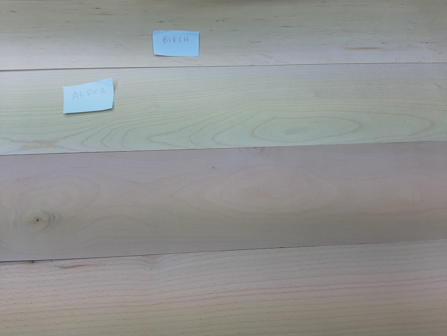
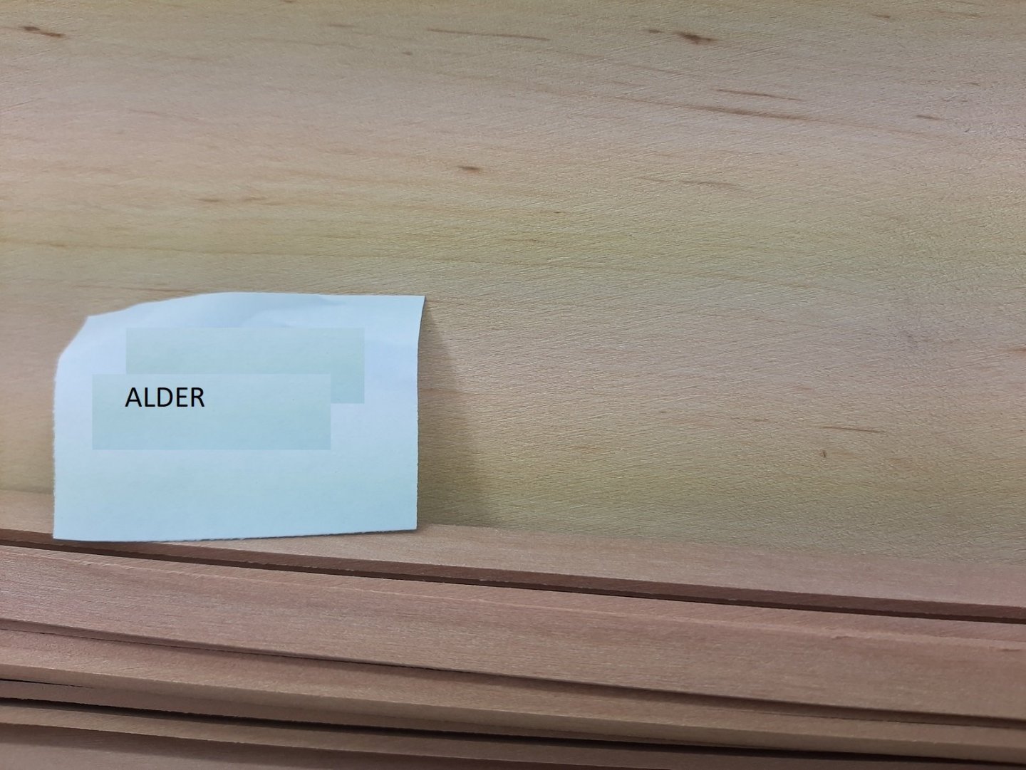
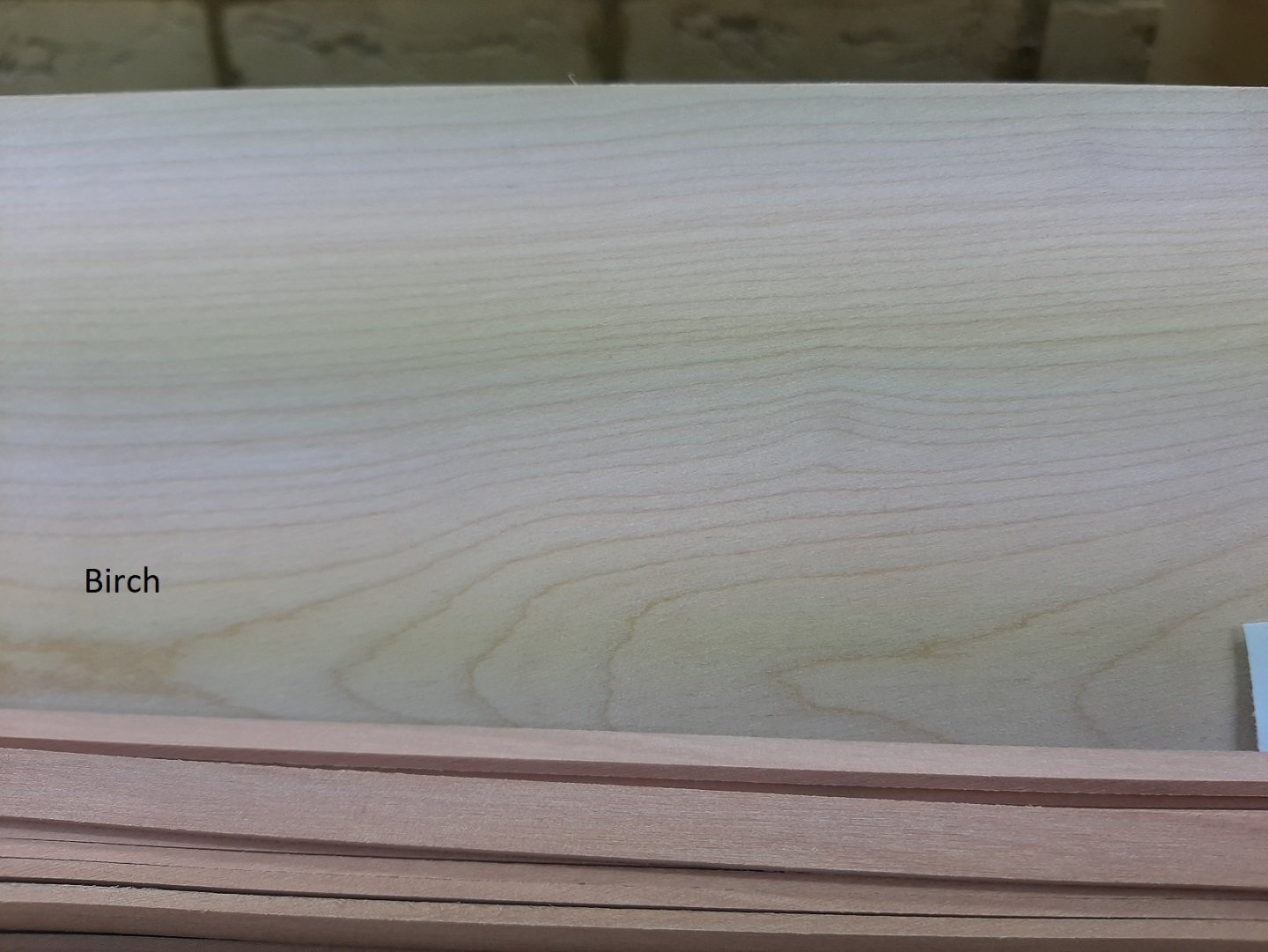
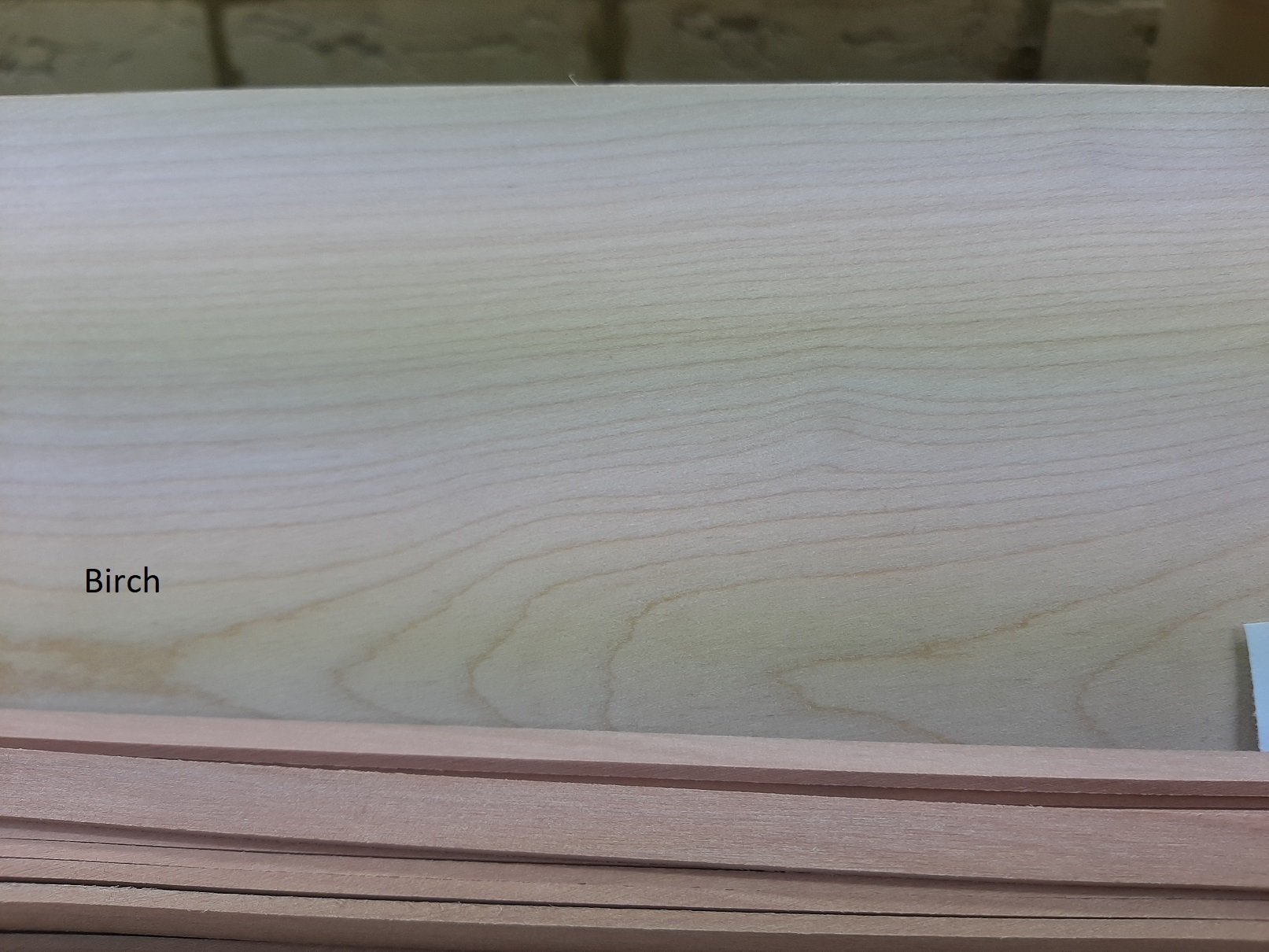
I did some more research and reasoning and indeed I got it wrong. The spotty wood is Alder and the nicer one is Birch. Both have a darker colour as they are kiln dried. The bitch plywood I got is much whiter as wood is not dried prior to processing. Another error is that the very nice wood I bought years ago, was not from massive holz but from Arkowood. That wood order was flawless, all strips dead straight, no knots and no colour variation. I emailed the chap to see if he has any beech sheets. His shipping fees are much cheaper as well. Michael, certainly timber stock is now nowhere near what it was in the turn of the previous century but, at least in Europe, cherry and pear seem to be in good supply as they are used as ornamental plants. Here in Cambridgeshire these trees are everywhere! Beech seems to be also plentiful. I would expect wood to be selected before shipped, considering that each 2x100x1000 mm pear sheet costs close to $10. GL, I never worried about ship worm in a model but how cool would be a log to replace worm-eaten planks in a model! Keith, I cannot mill my own wood, not even cut strips from a board. The only suppliers I know that carry a variety of woods and can cut any size strip/sheet are the above based in Germany. Massive Holz charges I think close to £30 for shipping and Arkonwood about £15. If you know any UK based suppliers that offer similar products, even with more limited variety, please let me know. Cornwall models does not carry what I need considering I work in large scales Regards Vaddoc
-
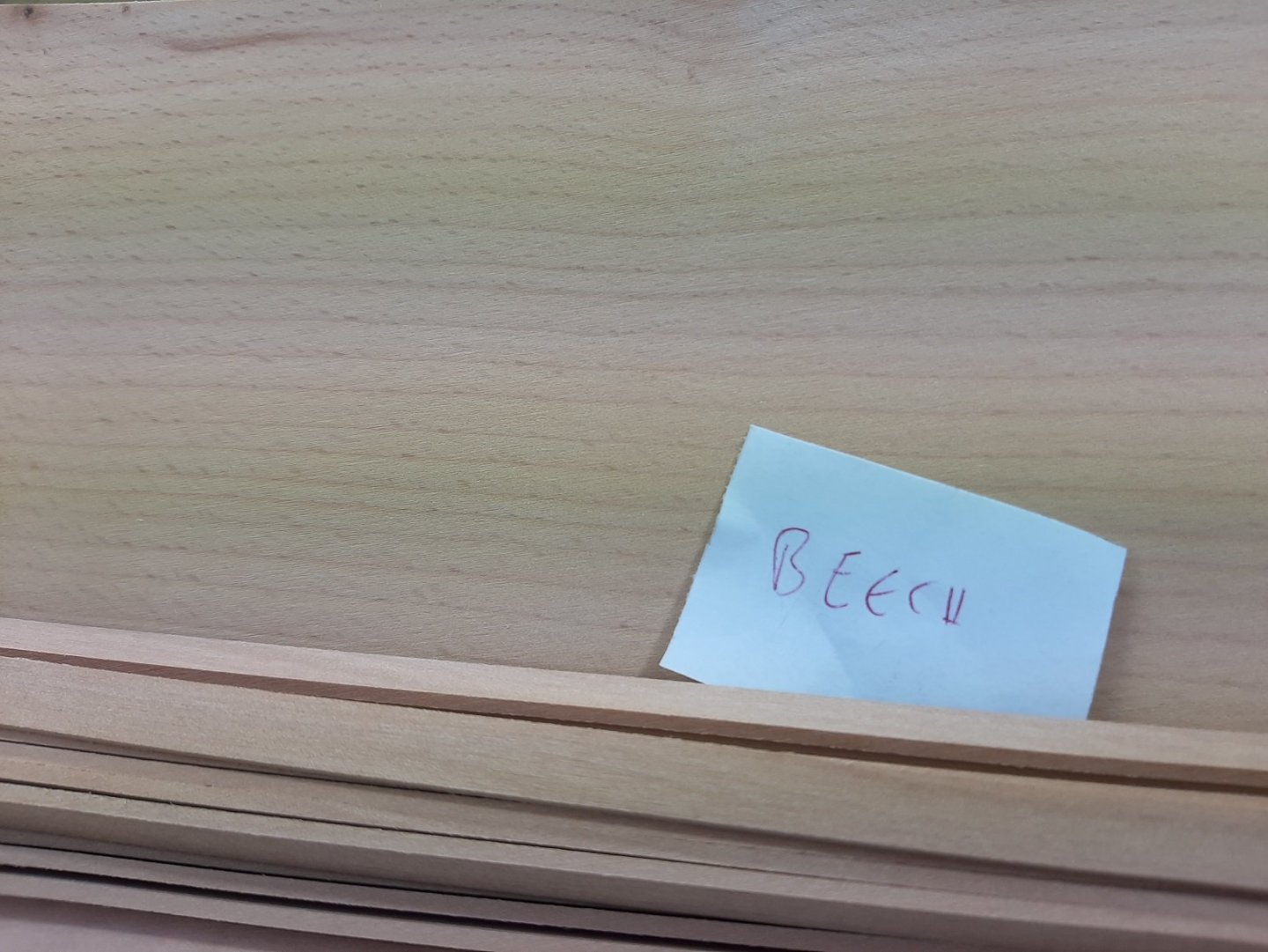
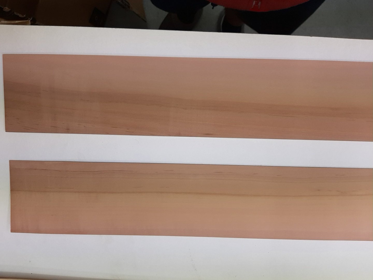
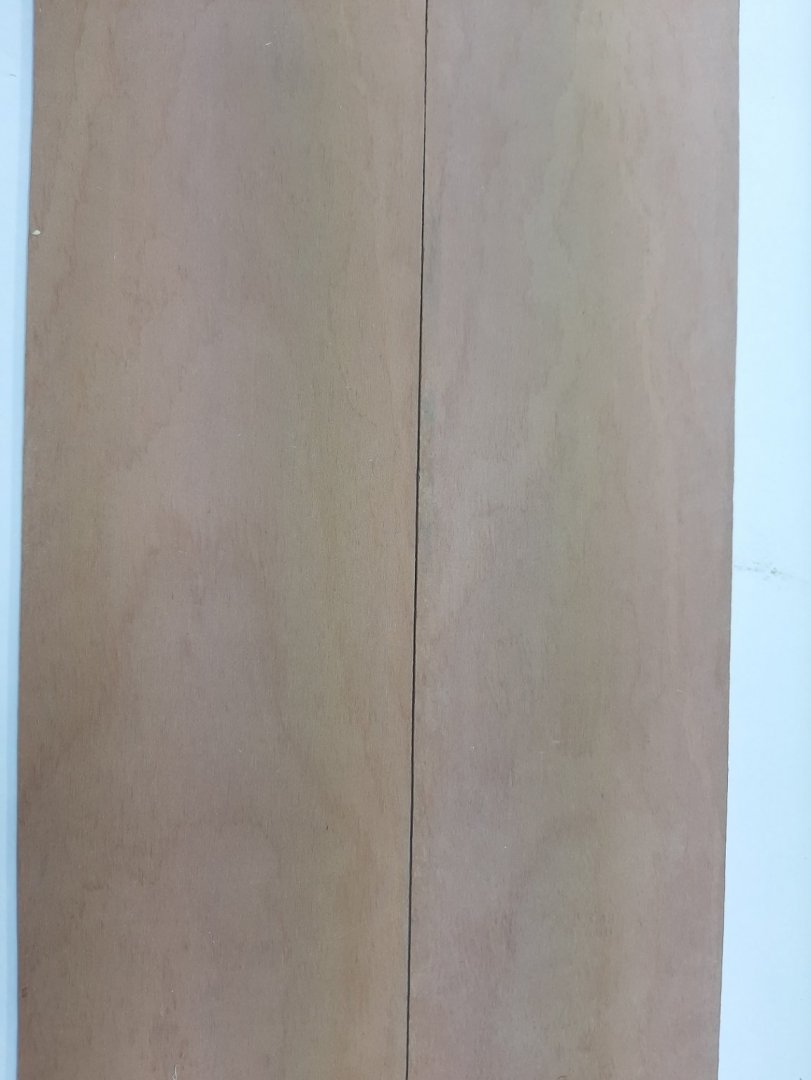
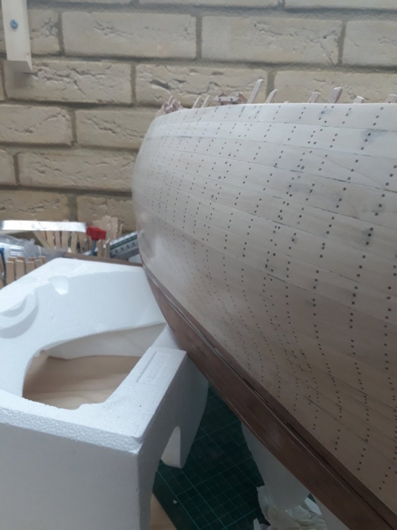
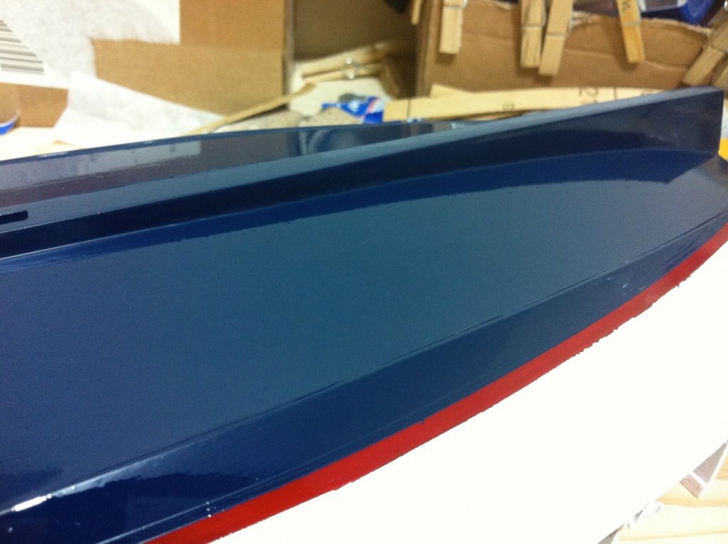
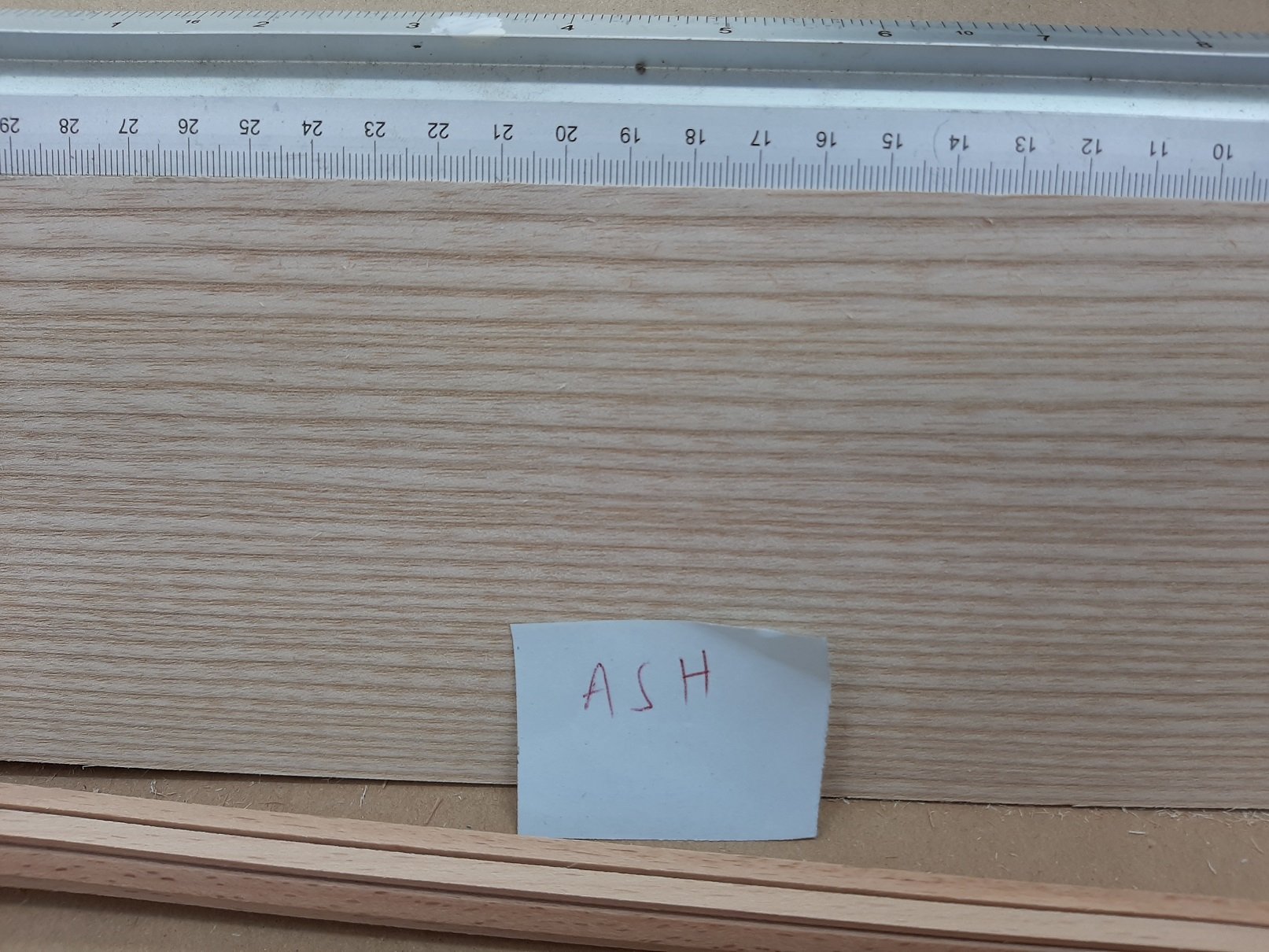
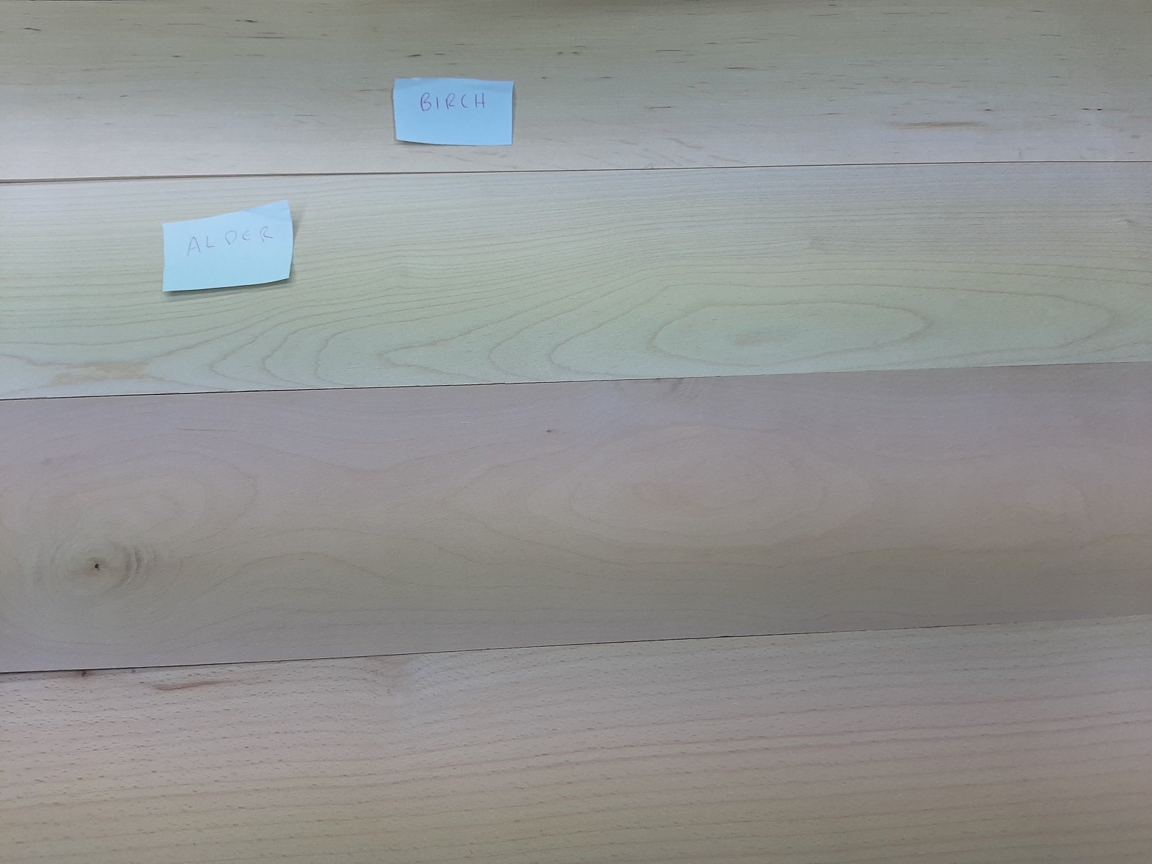
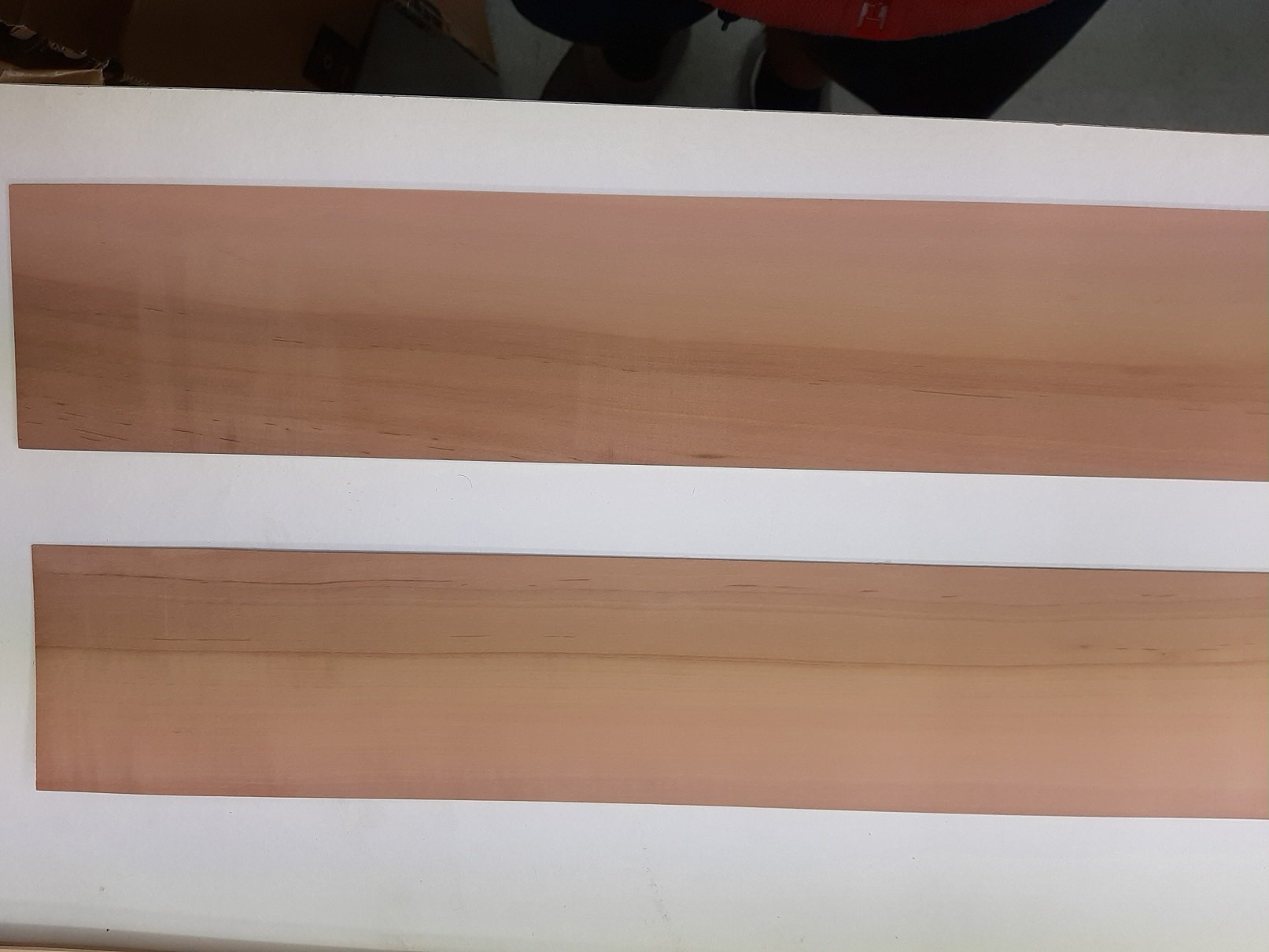
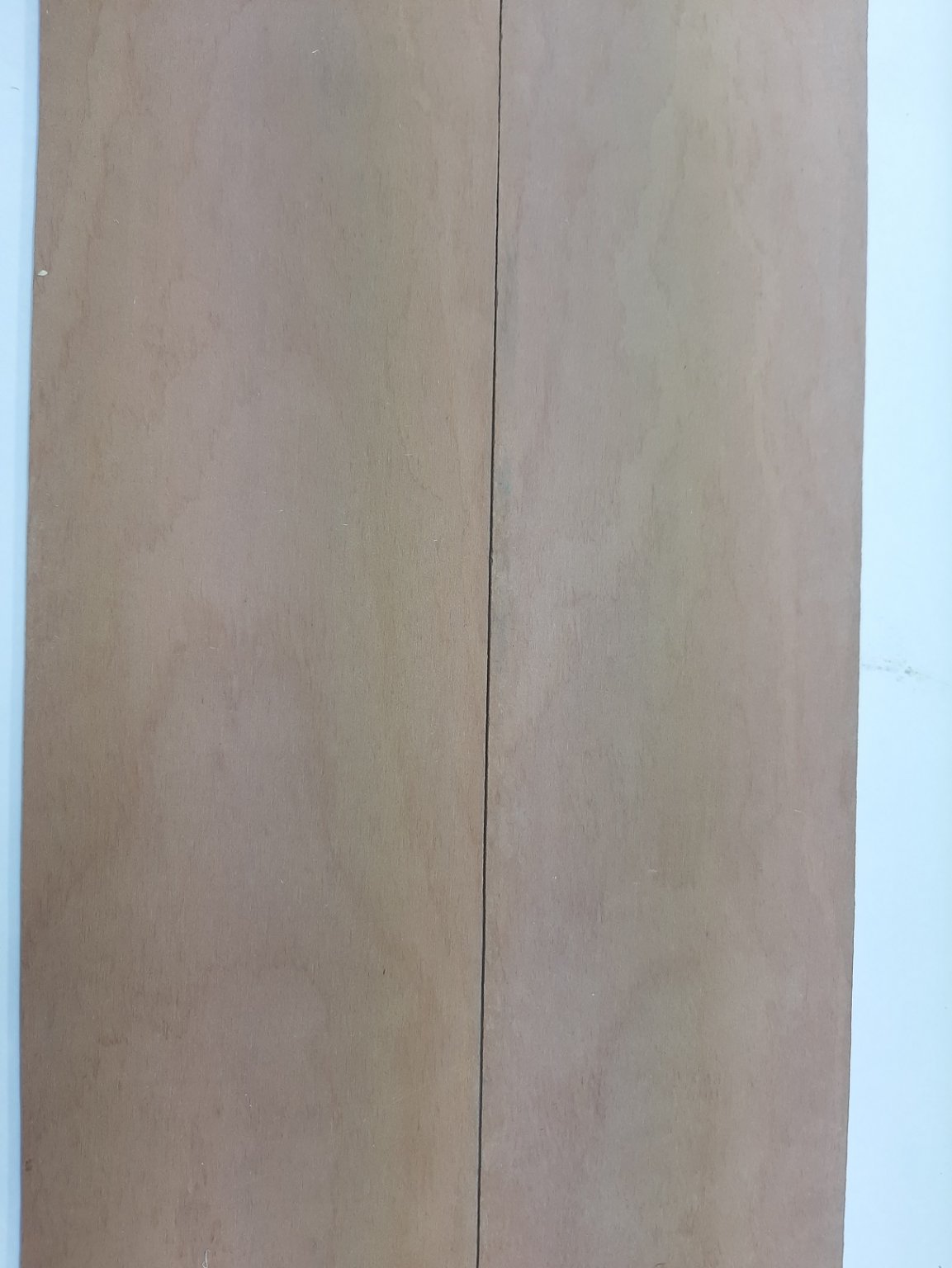
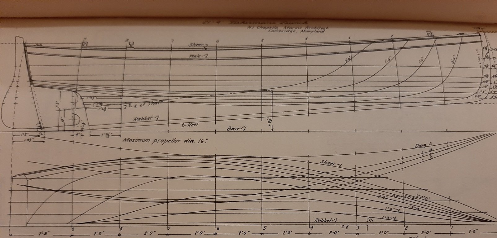
So, the wood is in! First however, a couple of pics of the Chapelle boat. This was only a quick fix but I got a continuous outer skin, more than adequately fair, and offset the surface for a plank thickness of 2 mm to produce the inner skin. The rest will be done nearer the building time. Back to the yawl now, I received various strips and sheets of pear, and also sample sheets of ash, birch, alder and beech. Excuse my very poor photos, I only have a cheap phone! Also, I am not 100% sure that I got right which wood was alder and which was birch. Ash really has such prominent growth rings that it is of no use for modelling. Now, pear has a pink hue and really does not combine well with Birch Alder that has a yellow hue. Also I did not like much the black spots and streaks Alder Birch is a much nicer wood, although wood data base suggests is quite soft. It looked fine for planking but again, does not combine well with the pink pear Beech on the other hand has also a pink hue and looks really good with pear! I do not mind the spotty appearance. Beech is I think my favourite wood! Beech it is then for the planking! In the next photo all the sheets are shown next to the pear wood Now, I must say that this time I am not entirely happy with the quality of wood I received from Massive Holz. These are the pear sheets I received Considering how expensive these sheets are, I would expect timber to be selected and such dramatic colour variations to be sorted. n my previous order, the colour of the sheets was much more uniform, the next photo shows two sheets I received many years ago, again from massive holz EDIT: This wood was bought from Arkowood So all has fallen into place and I have no more excuses for not making saw dust. Both time and money though are currently in short supply so further posts will be at the usual snail pace. Regards Vaddoc
.png.3d0dc57c9d0f993b441ec6158f4646fc.png)
.png.a87fe0d0448ffb5ef2dc6219c493d65f.png)

-
https://www.ebay.co.uk/itm/DecoArt-Multi-Purpose-Sealer-DS17-236ml/261972030617?ssPageName=STRK%3AMEBIDX%3AIT&_trksid=p2057872.m2749.l2649 Test your paint/finish on scrap and not the model! I use cheap plywood or plywood offcuts to see how various things react.
-
Yes, tack cloths are great, I use them as well. The alcohol rub is to remove any residual from the tack cloth, fingers or the mayo sandwich😁. Probably an overkill but painting a large hull is an equally big job, bit of a set back if it fails...
-
I wish you every success Bob!
-
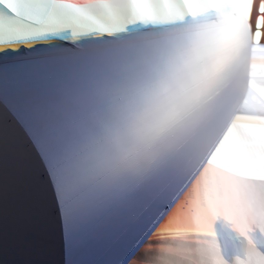
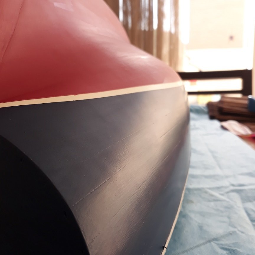
This is the hull of the Deben with all imperfections filled and sealed with sealer. Actually this was sanded to 240 grit and then rubbed with 0000 steel wool. Humbrol grey primer was sprayed prior to painting. It was very nice to touch! Between various coats it was wiped with isopropyl alcohol.
-
In the past I ve used a lot of humbrol or automotive primer (not good) but for wooden models is really not needed most of the time. There is no problem with adhesion and to smooth imperfections, a filler is needed. It might be useful if the colour of the underlying surface needs to change dramatically, for a large red surface applying a red or grey primer will reduce the number of coats needed. But since you can add 4 coats in an hour with acrylics, maybe not worth the cost and trouble. I usually sand away the primer leaving a thin smooth film. Never tried the Valejo primers, I ve been using the Humbrol white and grey spry can primers which I think are good but will not fill in imperfections. I like using sanding sealer as it seals the wood leaving a very smooth surface so the paint later does not soak into the wood and does not raise the grain. Painting on sealed wood is a better experience than painting raw sanded wood. I very much like the decoart/Americana water based sealer, the large bottle should last a very long time and has a very long self life. Dries in 15 min, sands very nicely. This sealer sits on top of the wood, filling the valleys and essentially levelling the surface. I usually sand the wood to 400 grit, apply a coat, sand smooth with 400 grit and repeat with a second coat. The surface should reflect light afterwards and be smooth and slippery. No worries, the paint will adhere very nicely. Never tried weathering, on my to do list! Do not dismiss enamels completely, they are wonderful. Low odour mineral spirit will allow you to paint in the house but cleaning the brushes is a pain, it takes a long time to dry so attracts dust and if you leave everything on the table waiting to add another coat in 6 hours, you will inevitably spill the mineral spirit on the table/floor and the admiral will not be impressed and will ban indoor modelling activities. Much easier to use acrylics...
-
Wefalck, to get good coverage with acrylics you really need a dozen or more coats. Thicker paint does not increase coverage, it just increases the chance of messing things up and reduces the self levelling properties of the paint. Bob, dry to wet means this: If you have a surface to paint, start on one side and paint a bit. Then continue working from the unpainted surface and ending to the previously painted segment so the two blend together. Do not rework the painted surface even if you see brush marks. If you have the right dilution and the right paint, the brush marks will disappear. Have a look at the following pictures. Both boats shown are very large, 1:12 and 1:10 scale. This is gloss blue enamel, only 2 coats, 6h apart I think. Great coverage and depth of colour. No brush marks! The boat is about 50+cm long This is Valejo acrylic, can't remember how many coats but they were many, 15 min part. Brush paint, no brush marks! The planks in this hull are 70+ cm long This is the same hull with Valejo matt polyurethane varnish on the red and satin on blue. The brush marks are actually the matt medium in the varnish that did not distribute evenly, matt varnishes are very tempermental. I am actually not good at all at painting. It is the modern paints and brushes that are so good. The Valejo hand brush thinner is very different than the airbrush one and has more stuff in than alcohol and water, it actually congeals. No ties with the company, I just like it a lot!
-
I did not like rattle cans Mark, too expensive, easy to put too heavy coats, needs a lot of masking and makes a mess. Acrylics dry incredibly fast (so they do not trap dust) but their coverage is very poor compared to enamels. I need 12 coats vs 2 for enamels. I always tell myself I ll use enamels and always end up with acrylics. The depth of colour is much greater with enamels. Use the brands' thinners, do not make your own. Valejo hand brush range is fantastic.
-
That was very interesting Frolick, many thanks!
-
Newbie starting with J-Class Endeavour
vaddoc replied to Sananda's topic in New member Introductions
Of course you do! 😉 Welcome Sananda, have fun building your boat. -
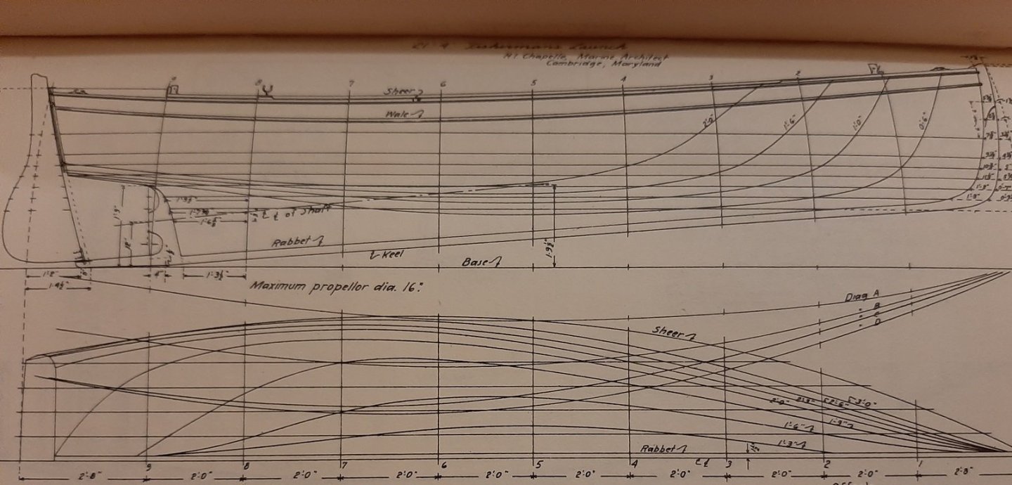
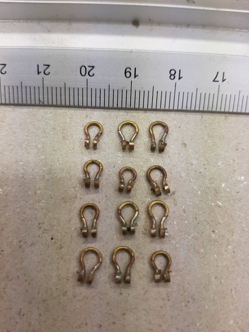
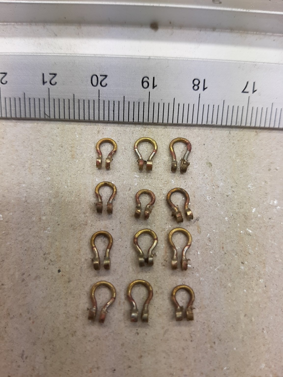
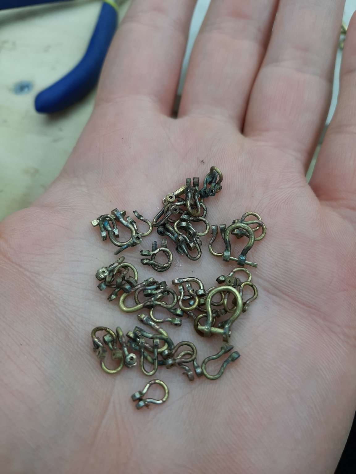
I ve been thinking on the 80/20 rule and I would like to share some of my thoughts with you. I hope it is not too much of a boring subject! I really liked Chapelle's book, the clarity of his thinking and the way he can communicate and explain complex issues is fascinating. So much so that I started CADing one of the boats in the book! Now, the following images I think really illustrate how ruthlessly (and unnecessarily) accurate CAD is. The boat is a workhorse fishing boat with an engine, no sails. Now, the offsets are given in feet, inches and eighths. This is how fair the lines are just as they come out of the offsets. (The white lines show how fair the curves are, they should not have picks and abrupt changes in curvature) This is the boat with all waterlines, buttocks and diagonals. They appear looking at them to work very well together, they are all very close and intersect very closely. Now, I faired all the lines but I did not do any true lofting at all, (although just fairing the lines is by itself a big part of lofting but it is a simple command with CAD). The next photo show how much more fair the waterlines are now compared to Chapelle's offsets. Now, based on these lines I produced the frames. These were also faired and just looking at the interaction with the lines, they appear very close. They are quite fair as well: Still, the computer thinks this accuracy is not enough, cannot produce a surface and will not compromise. From experience, I know that this horrible dent in the stern is because the frames and lines are just not fair enough. But they already are more fair than what Chapelle intended them to be! Now, I can solve this but it will need a pretty gigantic amount of work which is I now realise unnecessary. It is already more than accurate enough to be built as is. Just as a comparison, this is how fair the frames of the Yawl are! (they are very fair) Of course,the most important accuracy is the one achieved with the saw and the files which is not going to be CAD like. I will do some more work on the Chapelle's boat but will try and resist going crazy with the lofting. Maybe a little so I can produce a continuous surface to get the bevels of the last frame and the Transom. But I have no doubt that the wood will smooth everything out when bent on the frames. Back to the Yawl, the plywood order has come in. There are 2 mm and 1.5 mm sheets, these will be used to laminate dead flat and very strong 4 mm sheets to cut the temporary frames. I also received some cheap reading glasses (1.5x) from Amazon as a temporary measure. What a revelation! I can see! I made 12 shackles without a single failure and without my eyes getting tired and blurred. I now have about 70 (I made a few more since) but I ll make another 30 as I do not want to come back to this during the rigging. The wood from Germany is coming in tomorrow, I ll post pics in a few days. Vaddoc

.thumb.png.fd06b141710980ae07d2735980e16164.png)
.thumb.png.e55884bab8ba293ad8f7c2ea04b549af.png)
.thumb.png.73912f21555b19a59187ff9797a16783.png)
.thumb.png.0e3a7fd2fbe1b066949acc855883c0d6.png)
.thumb.png.422f3553d6d4e8bae1da392320cfe7b7.png)
.thumb.png.a1b111df495e0763061e3f0e310ab88d.png)
.thumb.png.4dbf13ed7456b5442d19f281a7ef82d0.png)
.thumb.png.f2d71ea72725fc435eb9883e11a6d00b.png)
.thumb.png.cee56738800fc982f1ceed4308823bef.png)
- 233 replies
-
- 11
-

-
adjustable height work area
vaddoc replied to Johnny Mike's topic in Modeling tools and Workshop Equipment
I have a bit different approach. I have a very high bench and use essentially a bar stool which I can lower as needed!😉 Your workshop is fantastic! -
Exploring FreeCAD for ship modeling
vaddoc replied to TonyM's topic in CAD and 3D Modelling/Drafting Plans with Software
I would not worry too much about the deck, the sheer is the important bit as it determines how high and how laterally the frames will end. This last screenshot looks much more promising. A CAD program though should be able to do much more for you Tony, certainly getting all these curved lines fair-ish. Another thing would be to fair the frames, sheer and rabbet, create a surface (planking) and then project vertical lines at whatever stations you want-this will be your new chosen frames and will give you instantly all the bevels. It should also be able to offset the surface by whatever plank thickness you choose so you ll end up with the inner and outer skins and all frames complete with internal and external bevels. Lovely! Vaddoc -
Actually I read that Victory at most could do 2 shots/3 min
-
Some boys would be killed in action and some hatches destroyed but then again some guns would also got damaged and/or their crews killed so the rate of fire would slow down after a while to much the slowing of the provision of shot from the hold. Still 75 guns would fire shot quicker than it could be replenished but then again each gun had a supply of shot already near the gun. At a theoretical rate of fire 2/min or 3 in 2 min, I would think that shot could run kind of short for individual guns after 20-30 min of heavy fighting. I wonder though if these ships could go on shooting each other at close range for much longer. 75 guns x 30 shot is a lot! Much easier to make calculations when not on board during the actual fighting!


.png.97fe30a042f1c07ec57f32c20361a67b.png)
.png.fe73feb8b9a52abb73d51394443c03c8.png)
.png.66455d5cc6fa977bd4b72da6f7cf8bce.png)
.png.f51bfce711a54a9e8f6b84d945503189.png)
.png.9e8c40ae79175513c1c72b9ccf6b3214.png)
.png.1133aad44c31c70220a619356bd922ab.png)
.png.9de2d4782f563fbd6a6a79cc2799f7f7.png)
.png.64944eeb534b66998519b0f5da5cd6bf.png)
.png.4ca46cc3c5cdd4538ea25bb26507b847.png)