

.jpg.f26acc9a74319261612561bfa7da1303.jpg)
vaddoc
-
Posts
1,605 -
Joined
-
Last visited
Content Type
Profiles
Forums
Gallery
Events
Everything posted by vaddoc
-
.thumb.jpg.6fd4c1b78768bb3efd745ab810936005.jpg)
Hi from Azores and thank you all in advance
vaddoc replied to Marco Silva's topic in New member Introductions
Welcome Marco, good luck with your boat! -
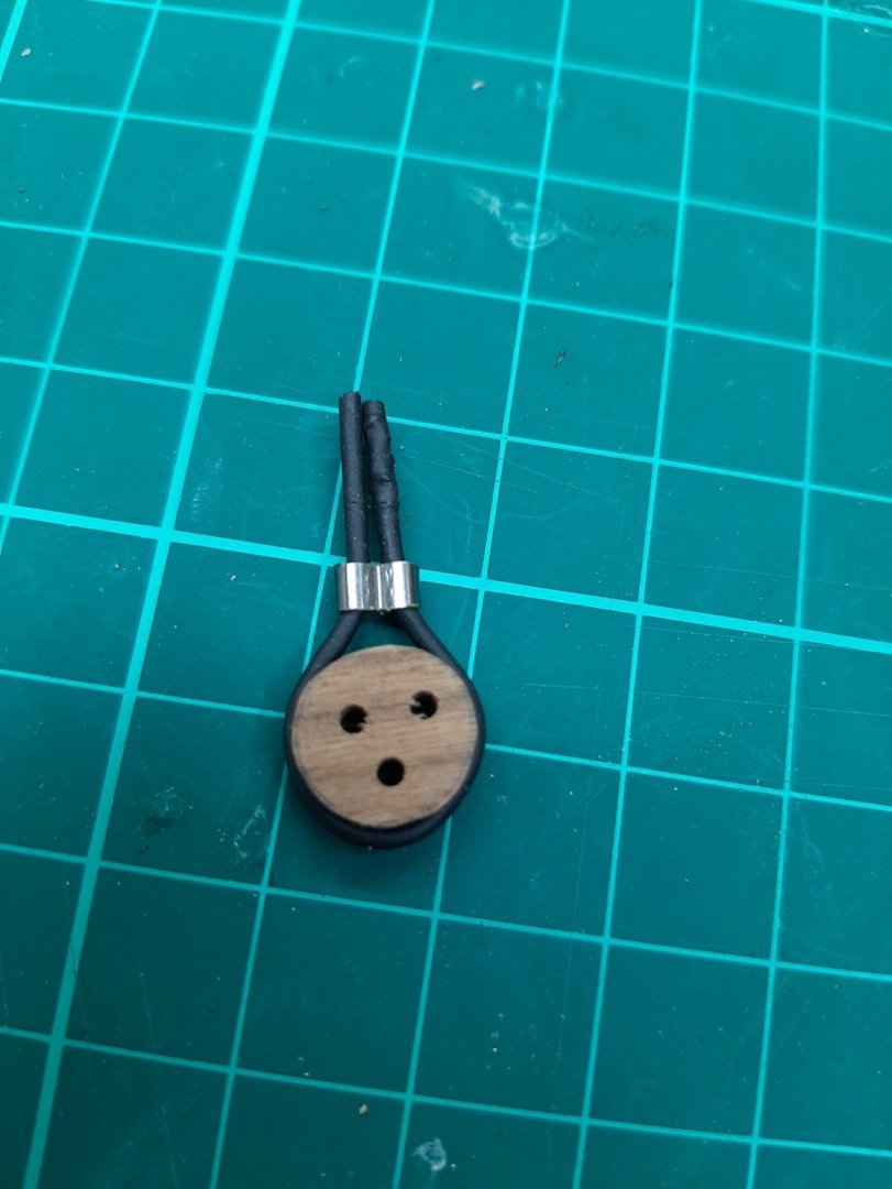
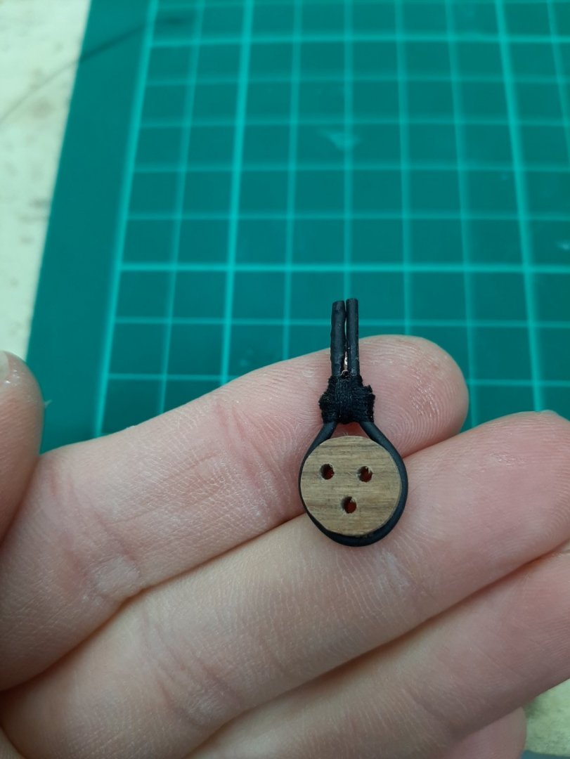
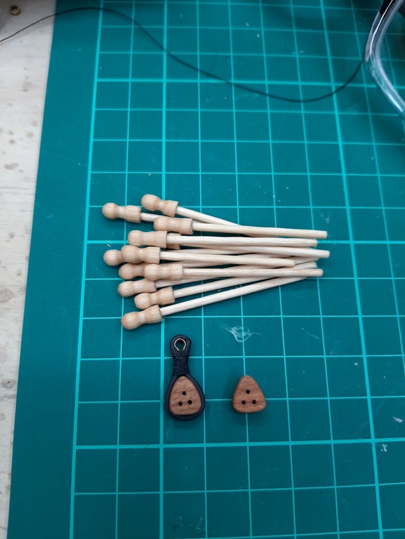
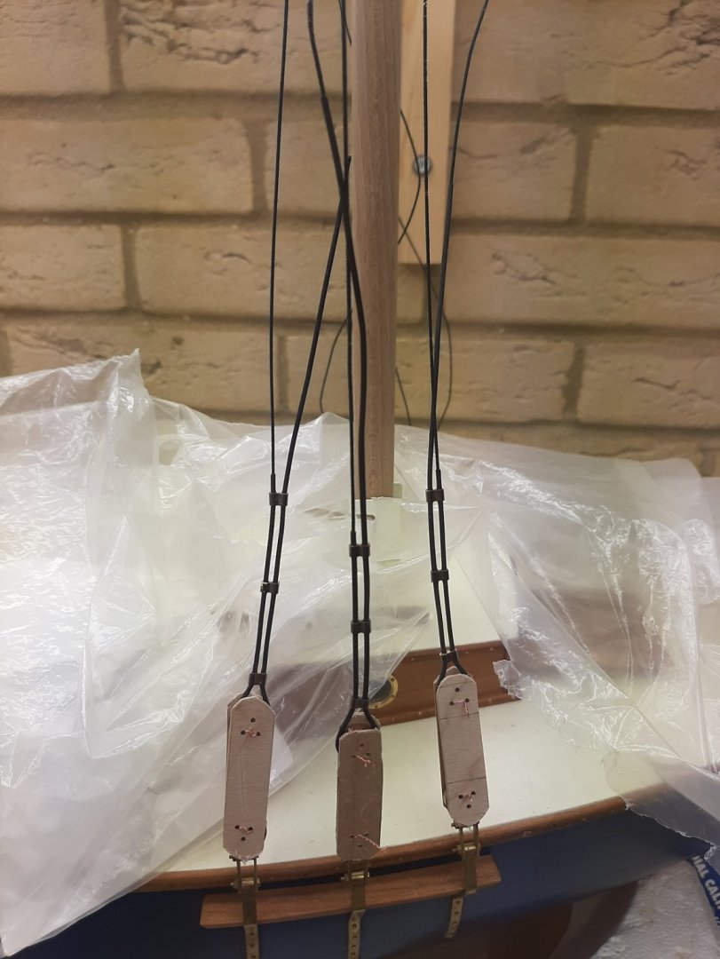
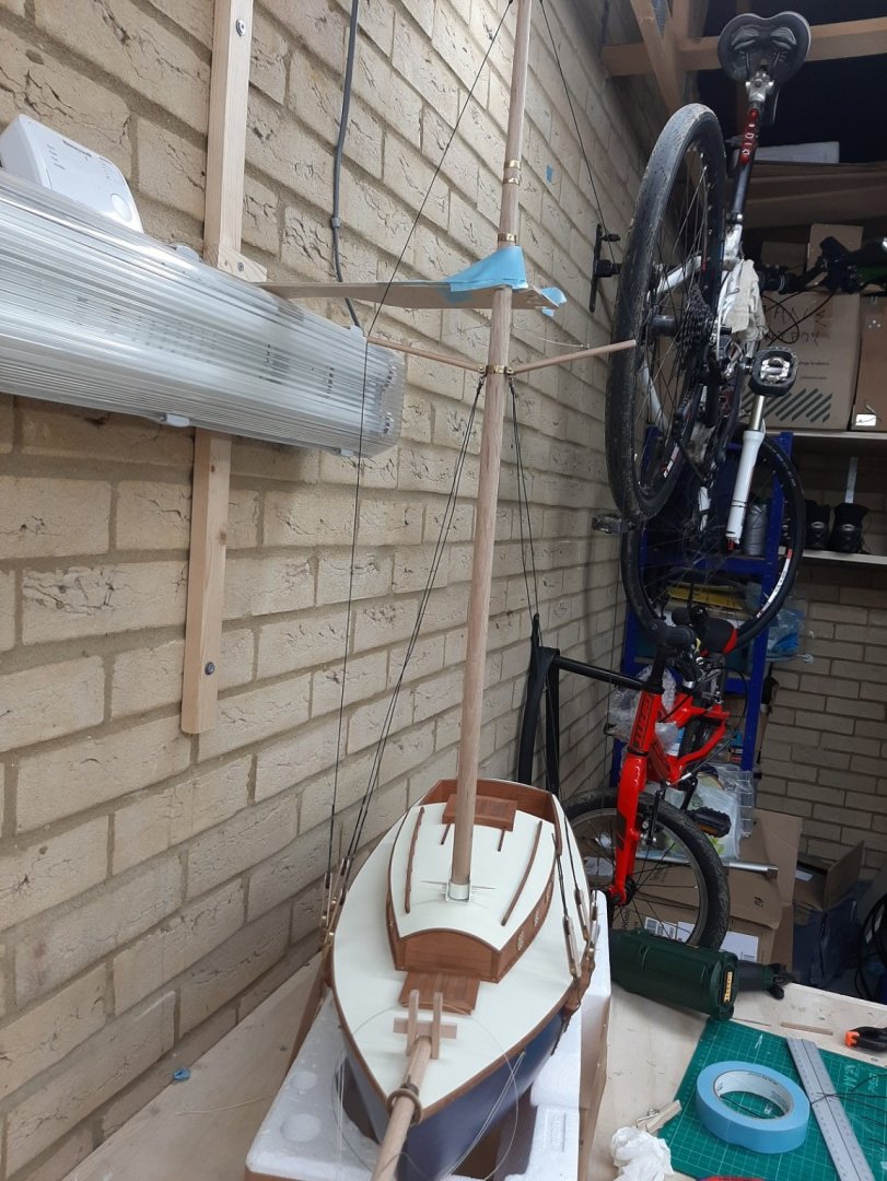
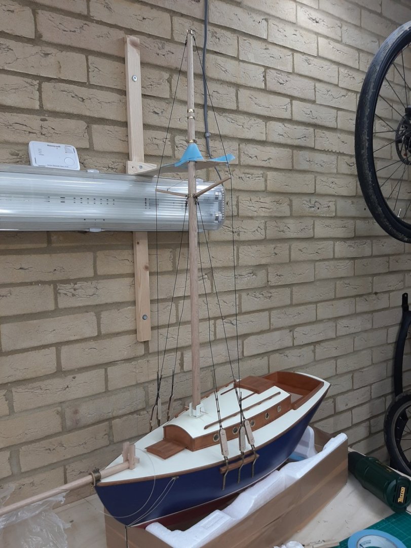
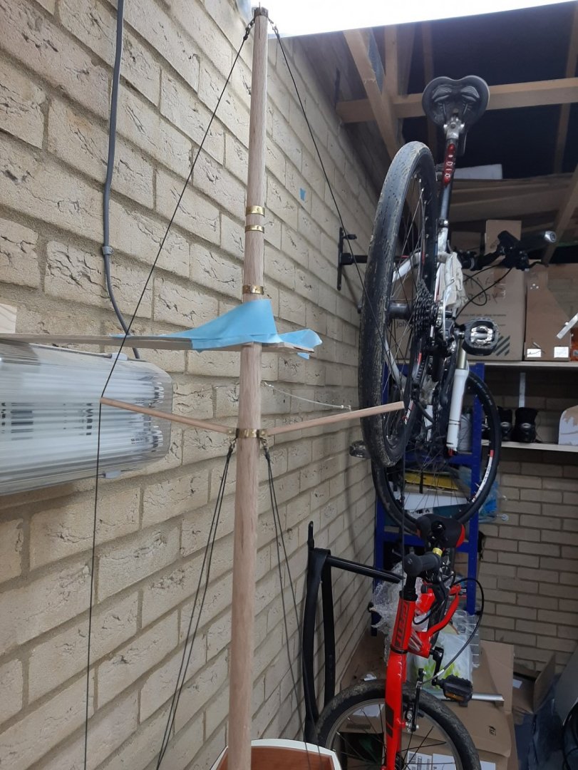
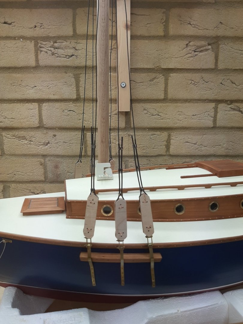
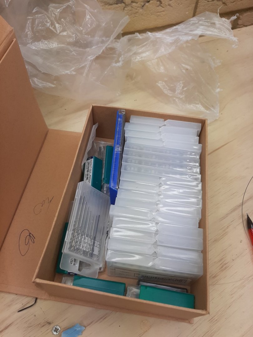
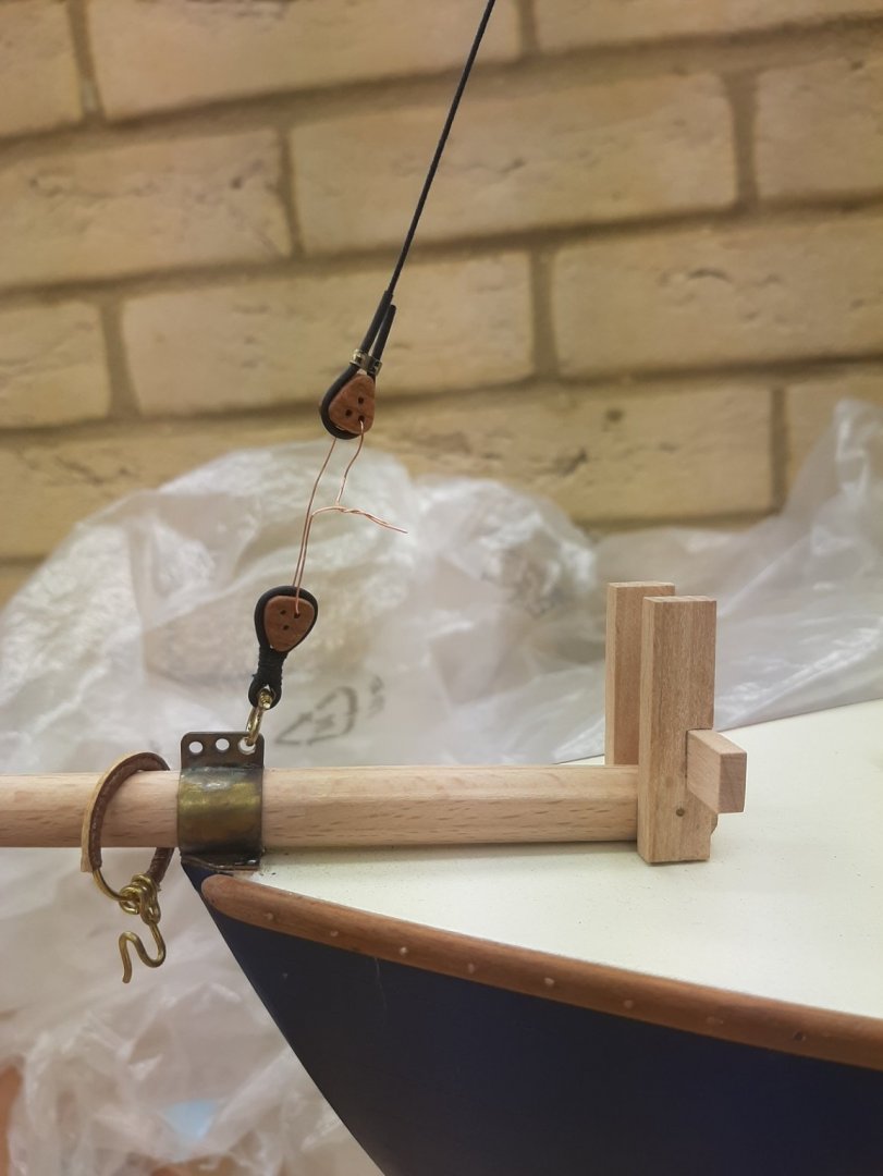
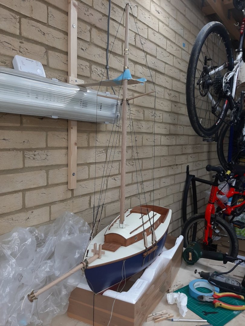
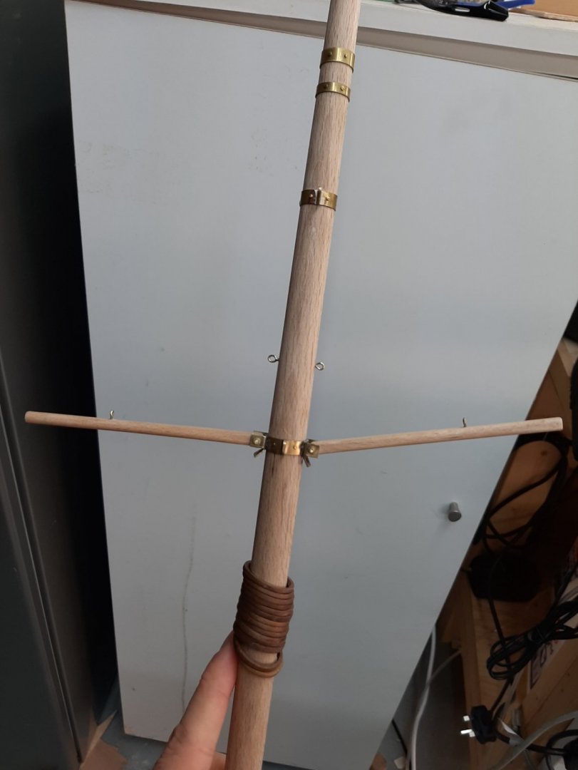
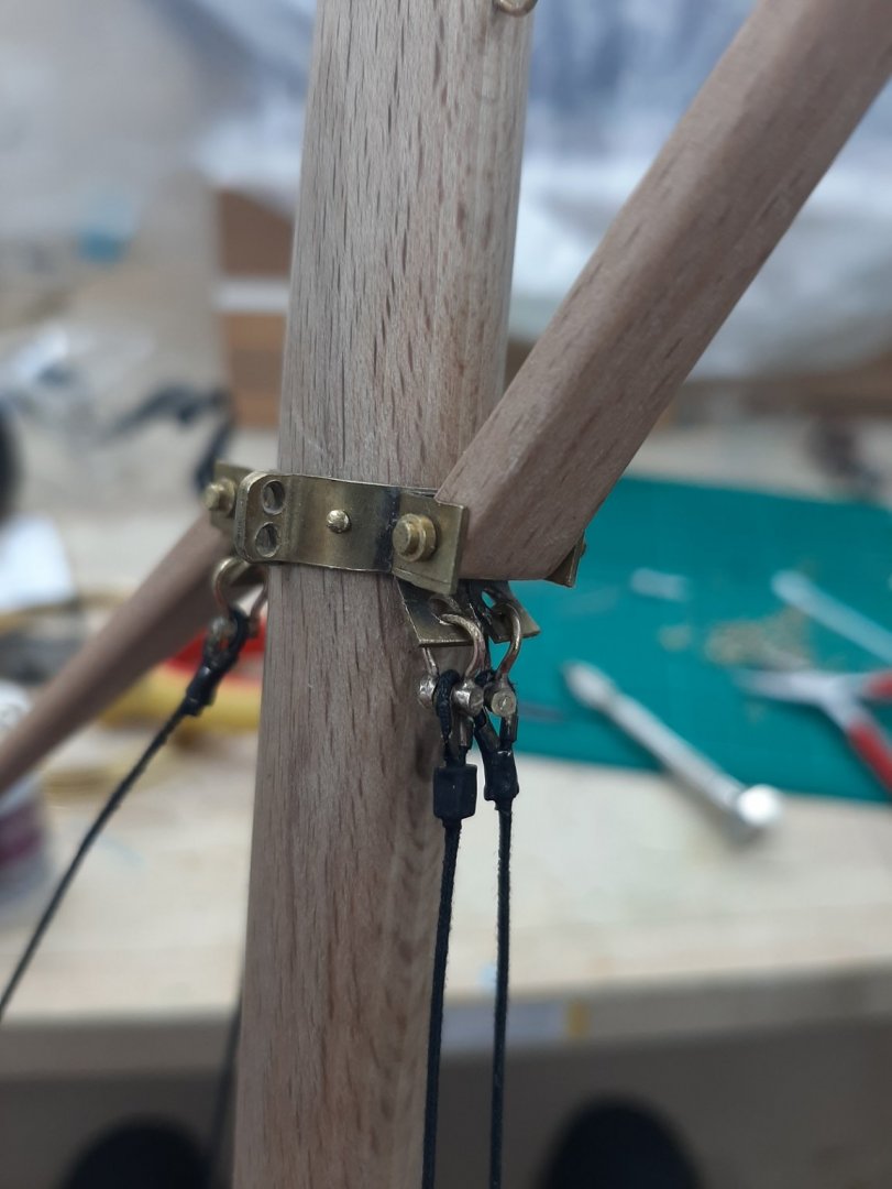
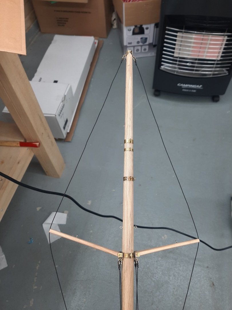
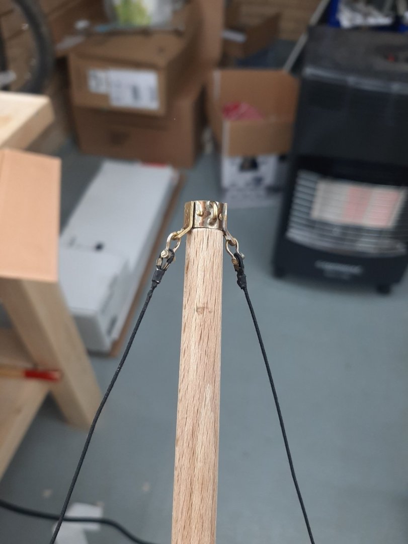
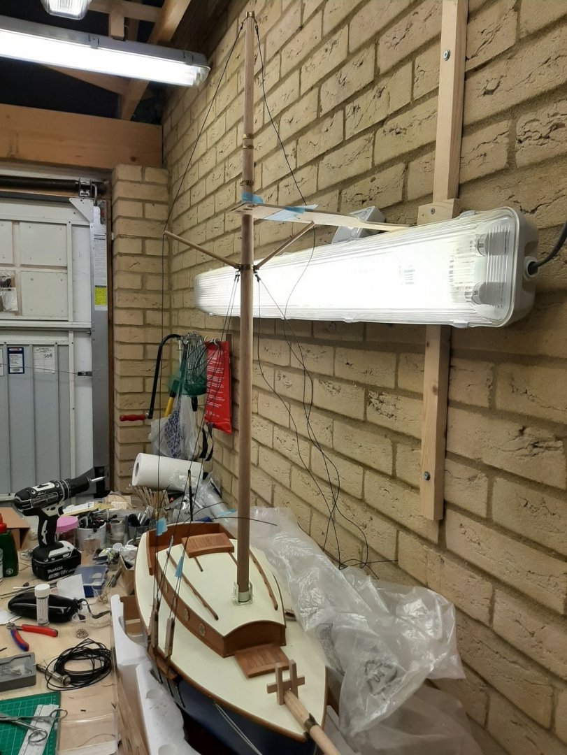
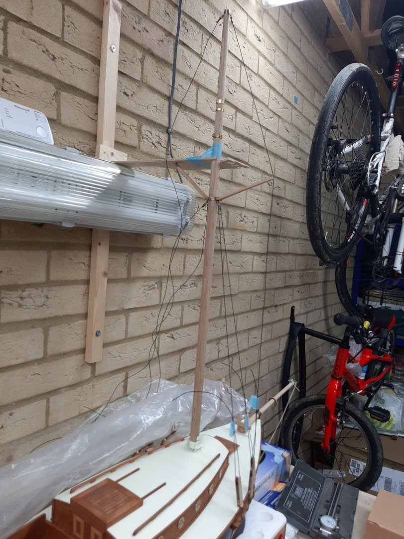
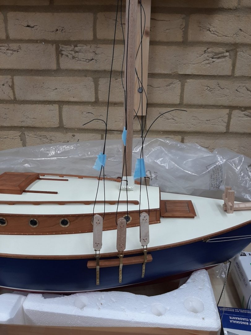
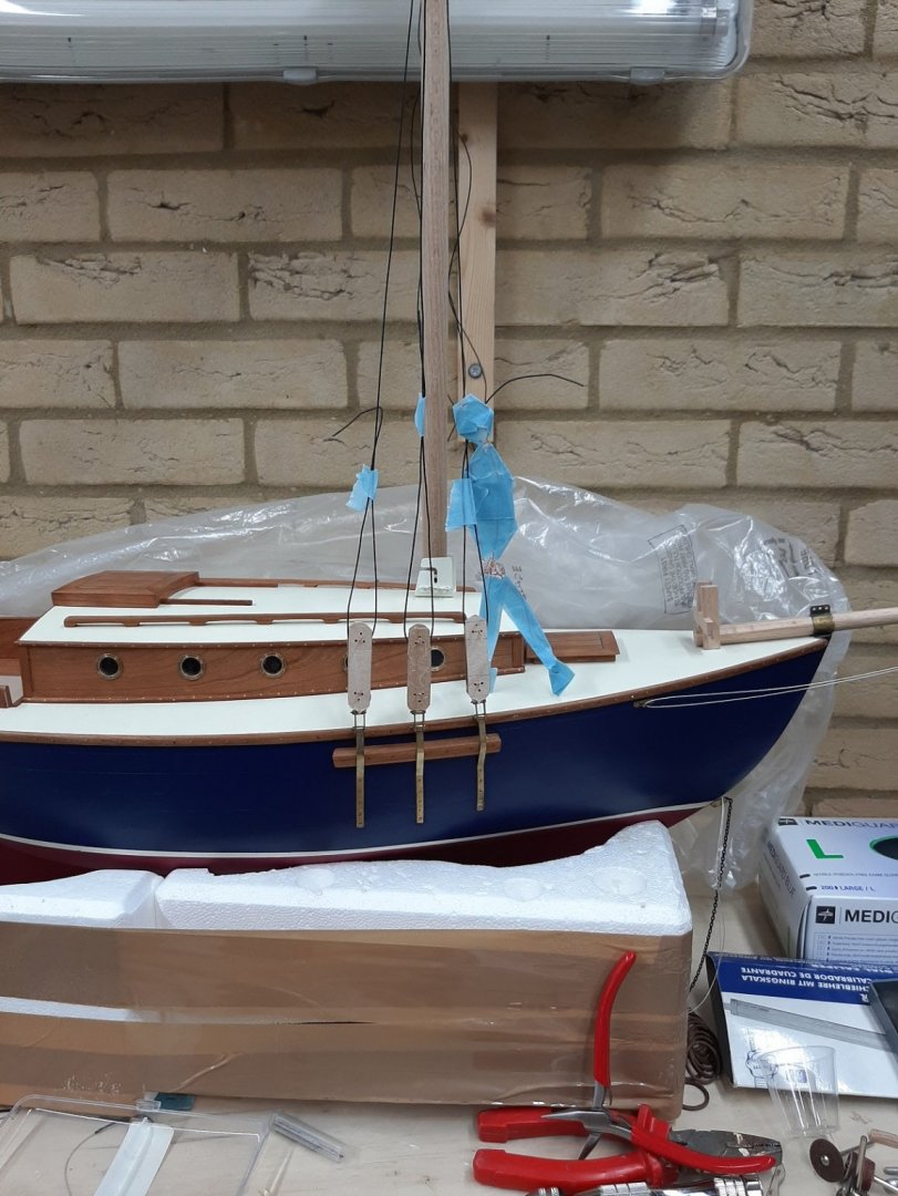
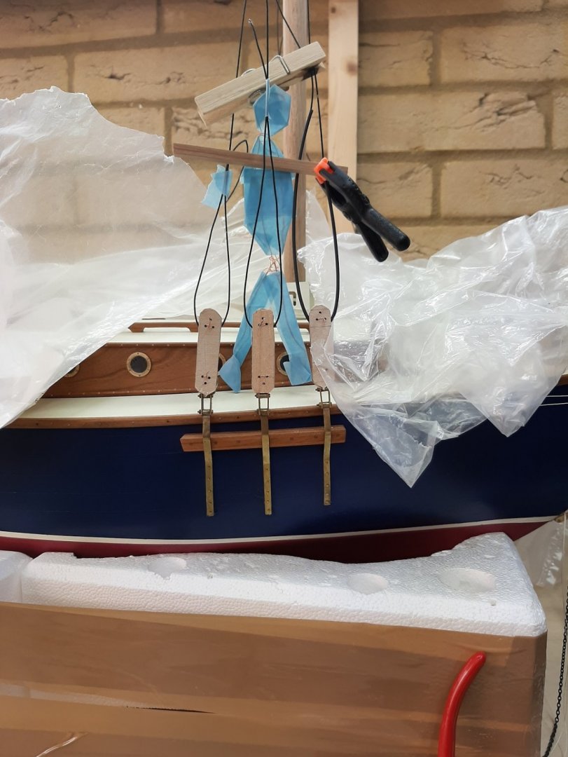
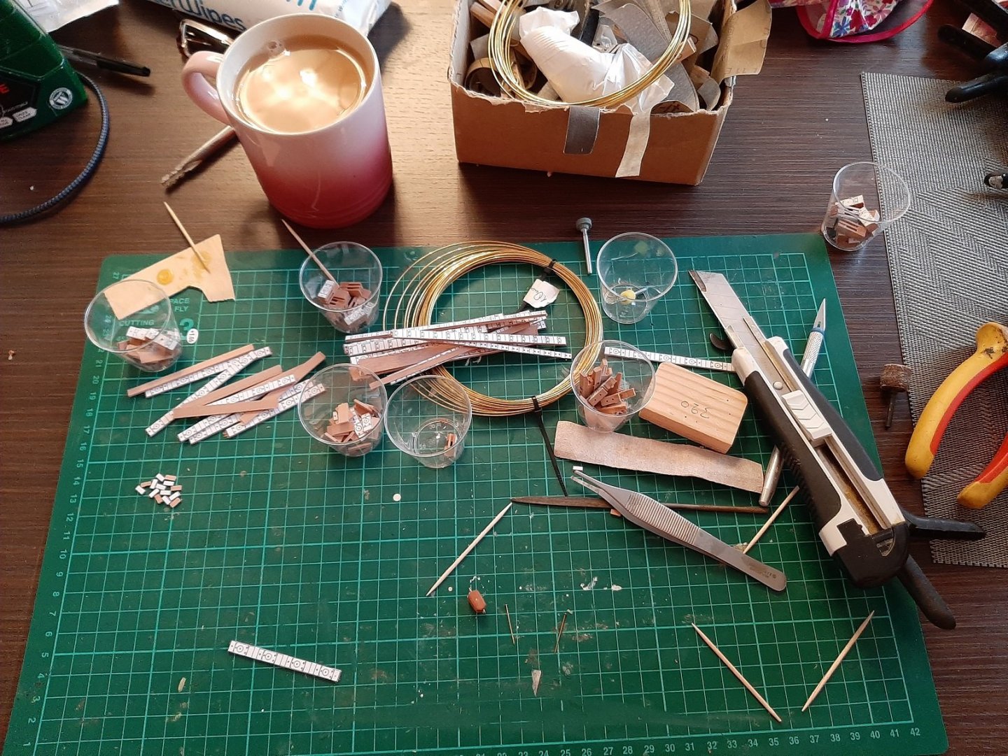
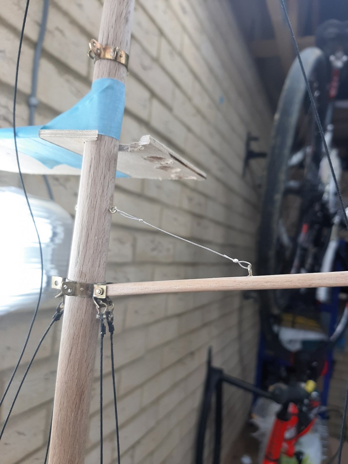
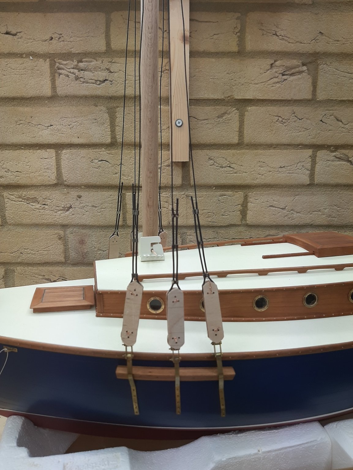
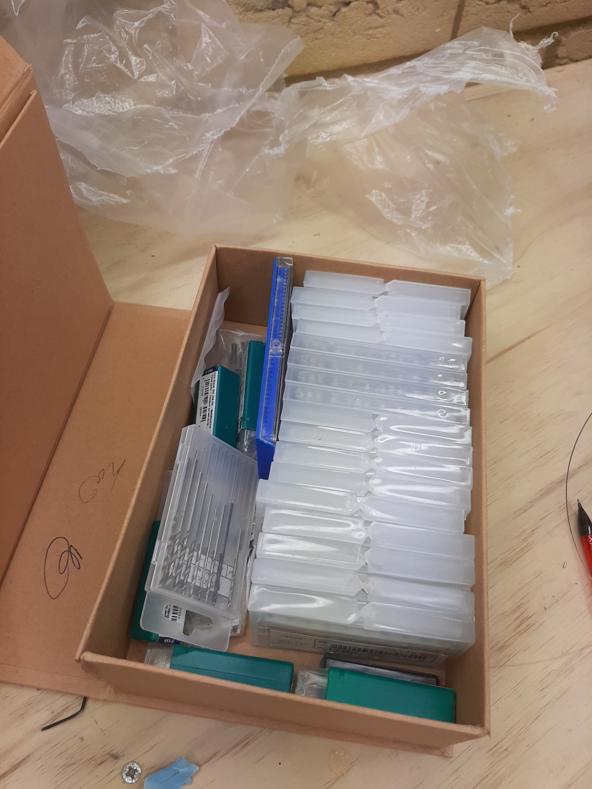
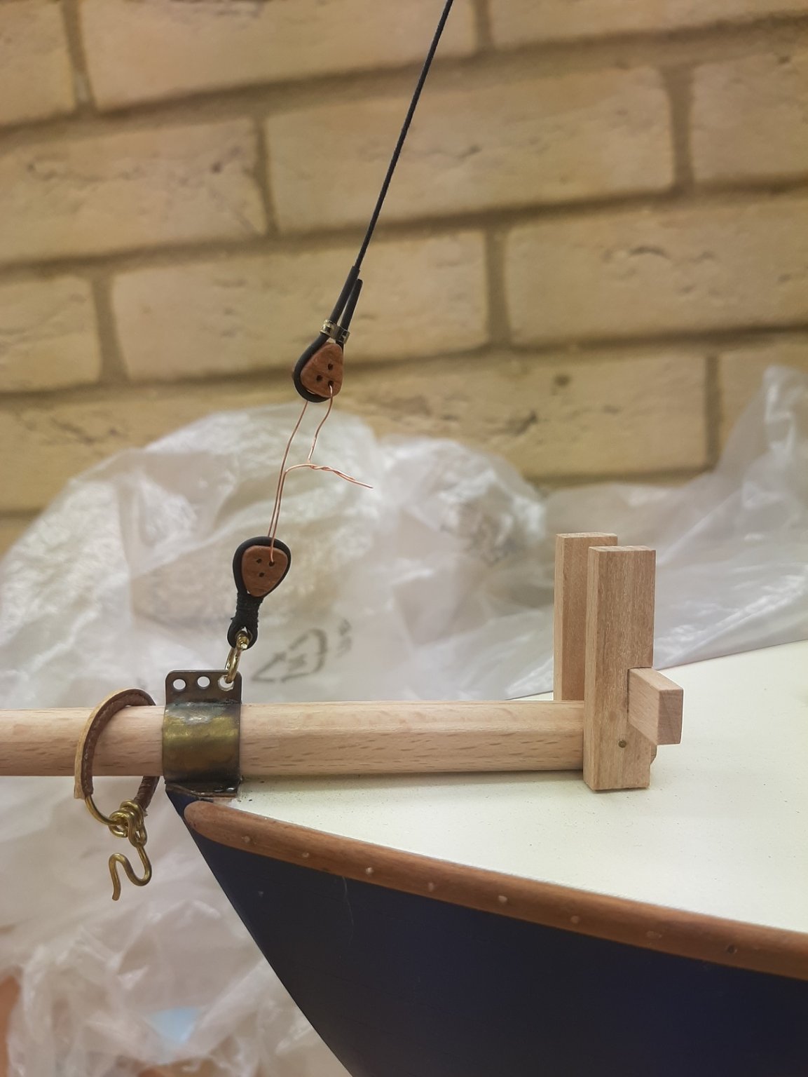
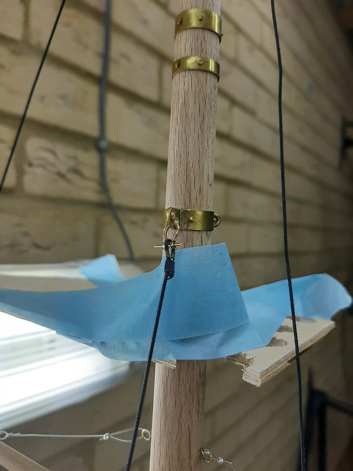
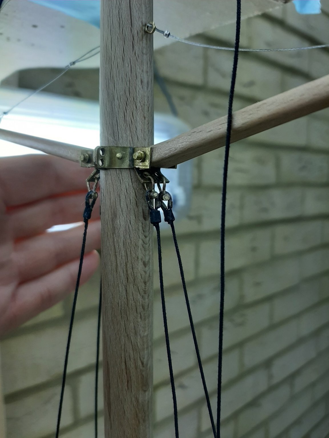
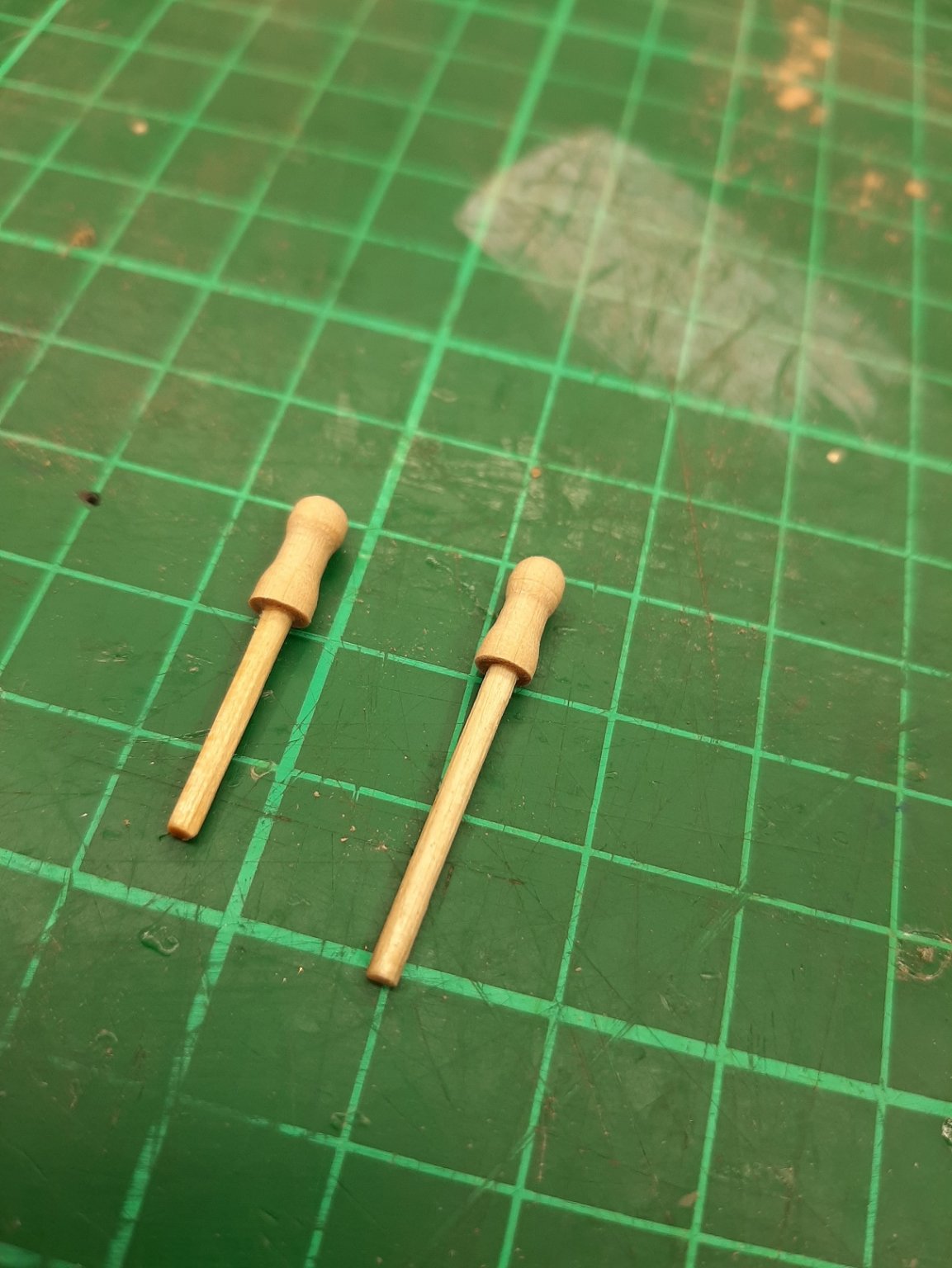
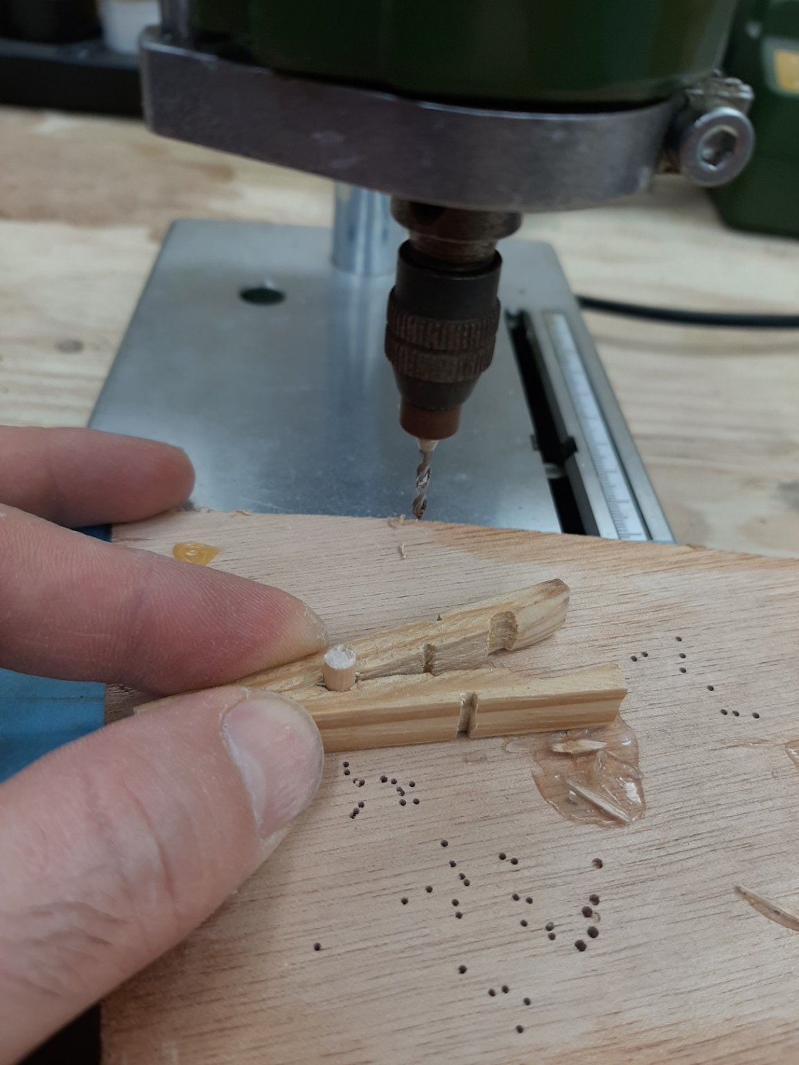
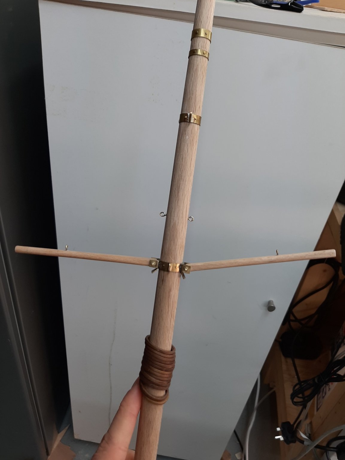
I think maybe another update might be in order as I was allowed to spend quite some time in the garage. First of all, a photo of the finished belaying pins. They have a coat of Tung oil on but the colour of the wood barely changed. I also took a photo of my drill inventory-part of it at least. You can never have enough drills. I did an experiment with seizing the lines. This is wire rope, seized with black thread and encased in shrink tube. The crimps are fishing crimps cut in three. It looks ok I think. One side done. Note that the ropes are not touching but I think after the crimps have been seized with thread they will come closer together. I attached a piece of wire rope to temporarily hold the spreaders in place. The other spreader was badly attached so I had to remove it, fill the pivot hole and re-drill. A few more photos, the boat is large and is difficult to get good shots I also installed the forestay. The bowsprit had taken some nasty bumps over the last few months and I noticed it was loose. I glued it again but I must remember to be careful. With the bob stay on, it should be more secure. Suddenly it feels that the end is very close! A couple more photos


-
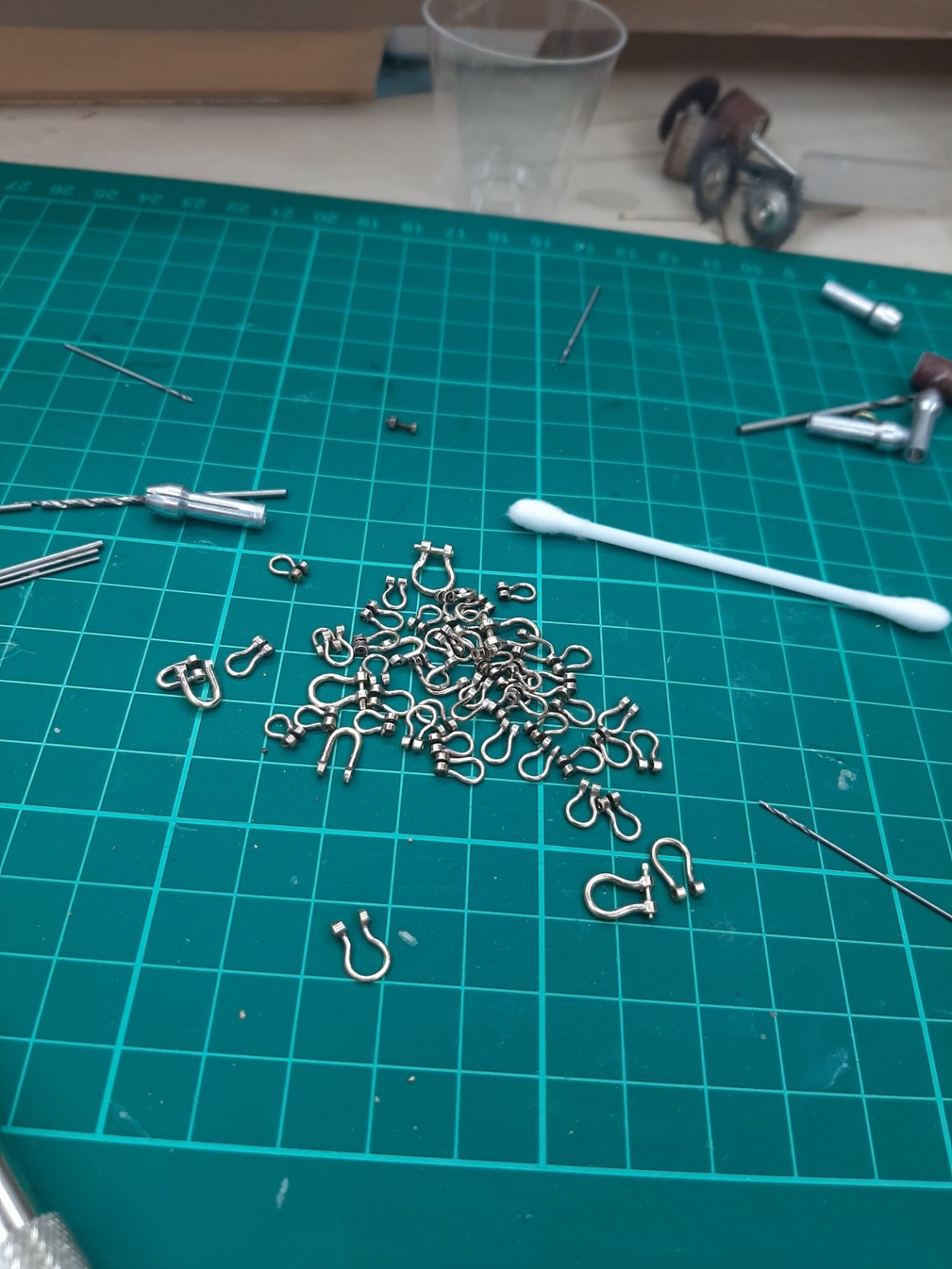
Thanks to all! Deuxey, the shafts on the pins were temporary to allow spinning of the heads for shaping. The pins now have very long shafts that will be cut to length later on Keith,making shackles is easy and actually fun! You will find very useful the thin grinding discs that Proxon sells to cut and shape the brass. Mark, I have drawn up the rigging (most of it anyway) except for the sheets for the jib and staysails-no idea how these will be. There is always the chance I ll need more than I have. I was not aware it is called "becket", learned a new word! Regards Vaddoc
-
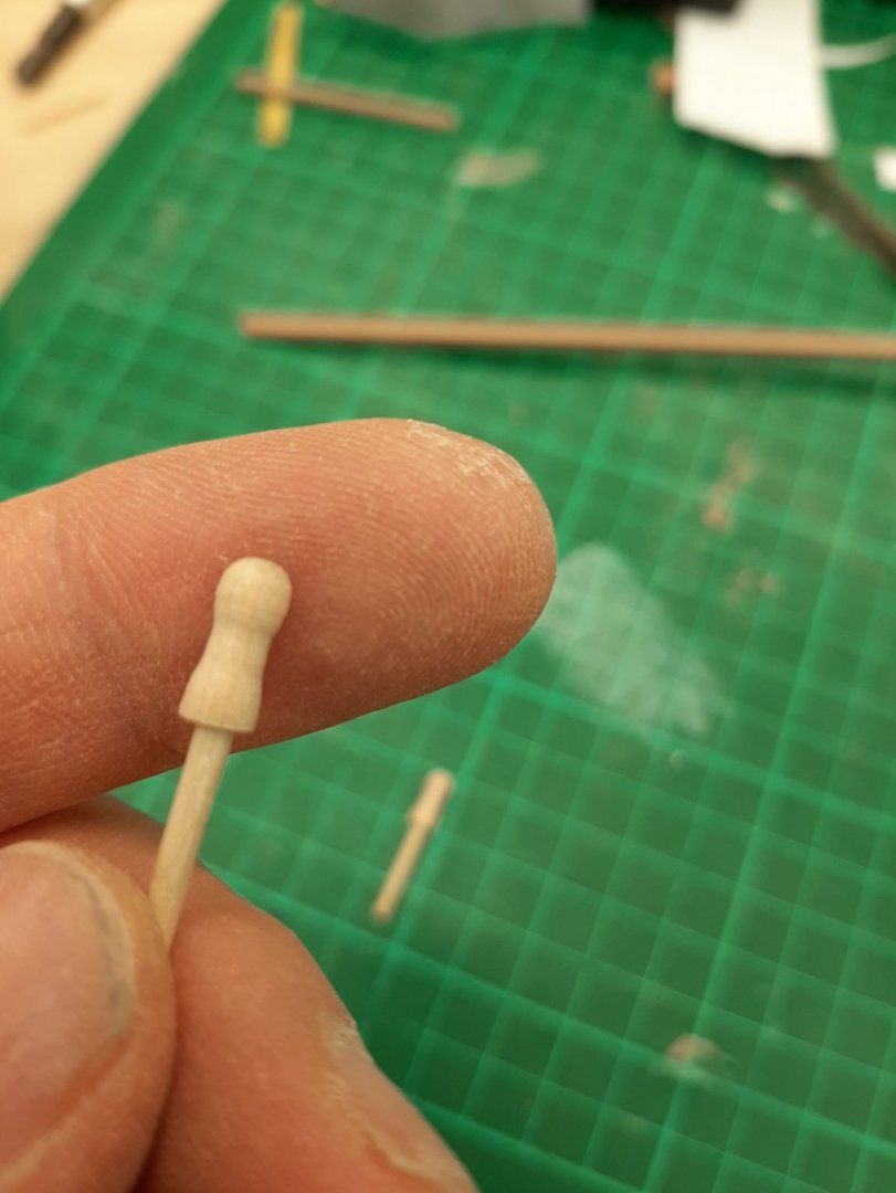
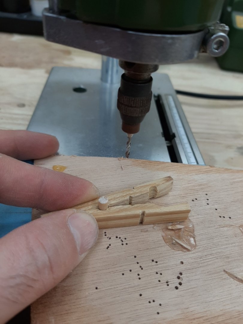
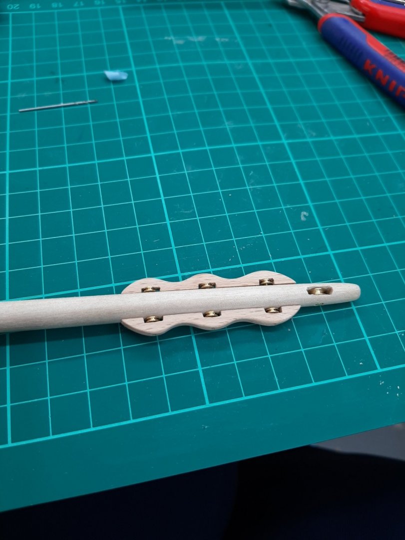
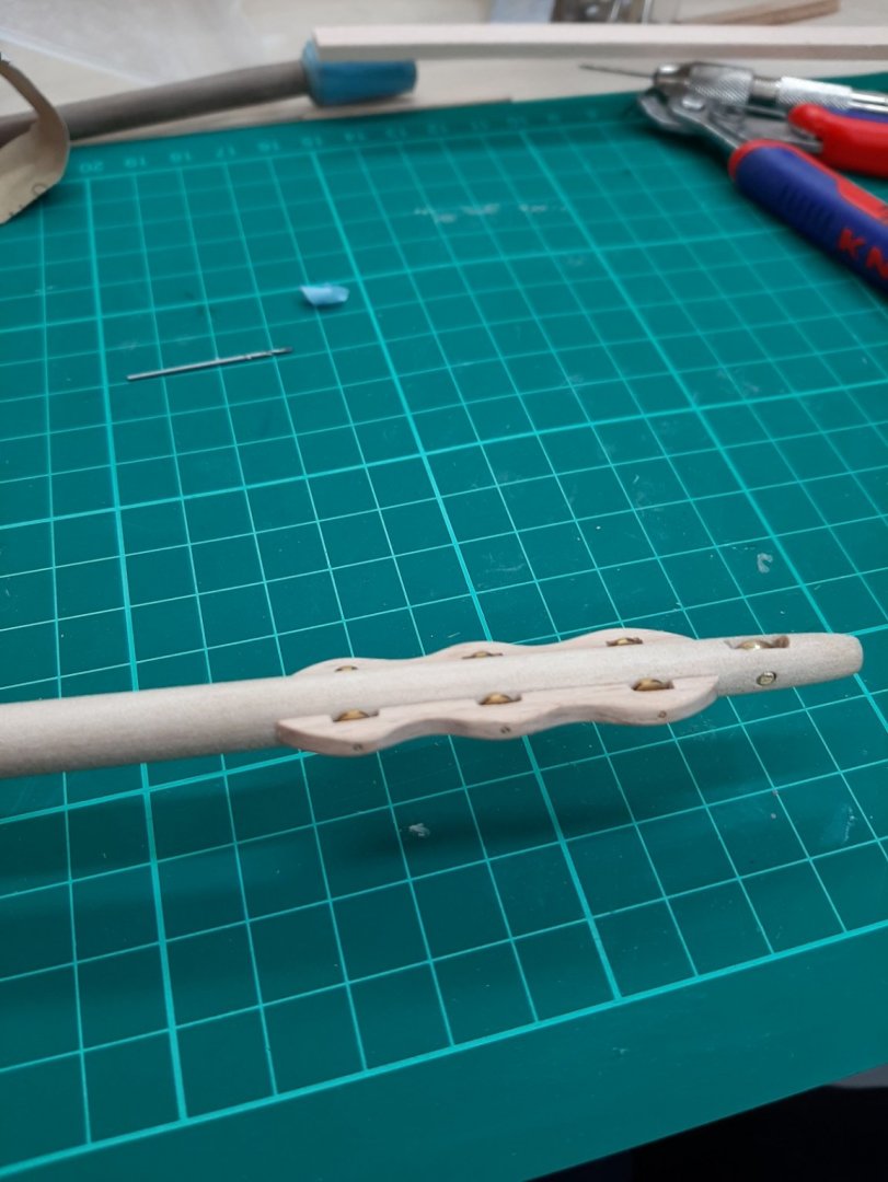
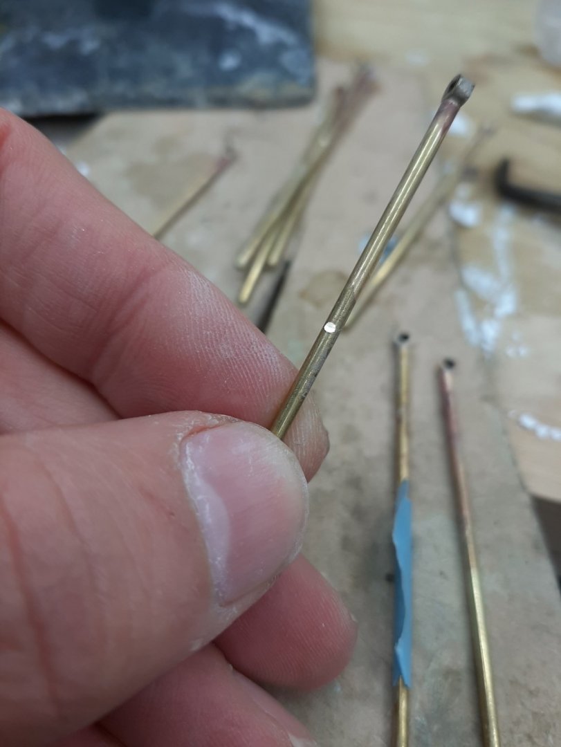
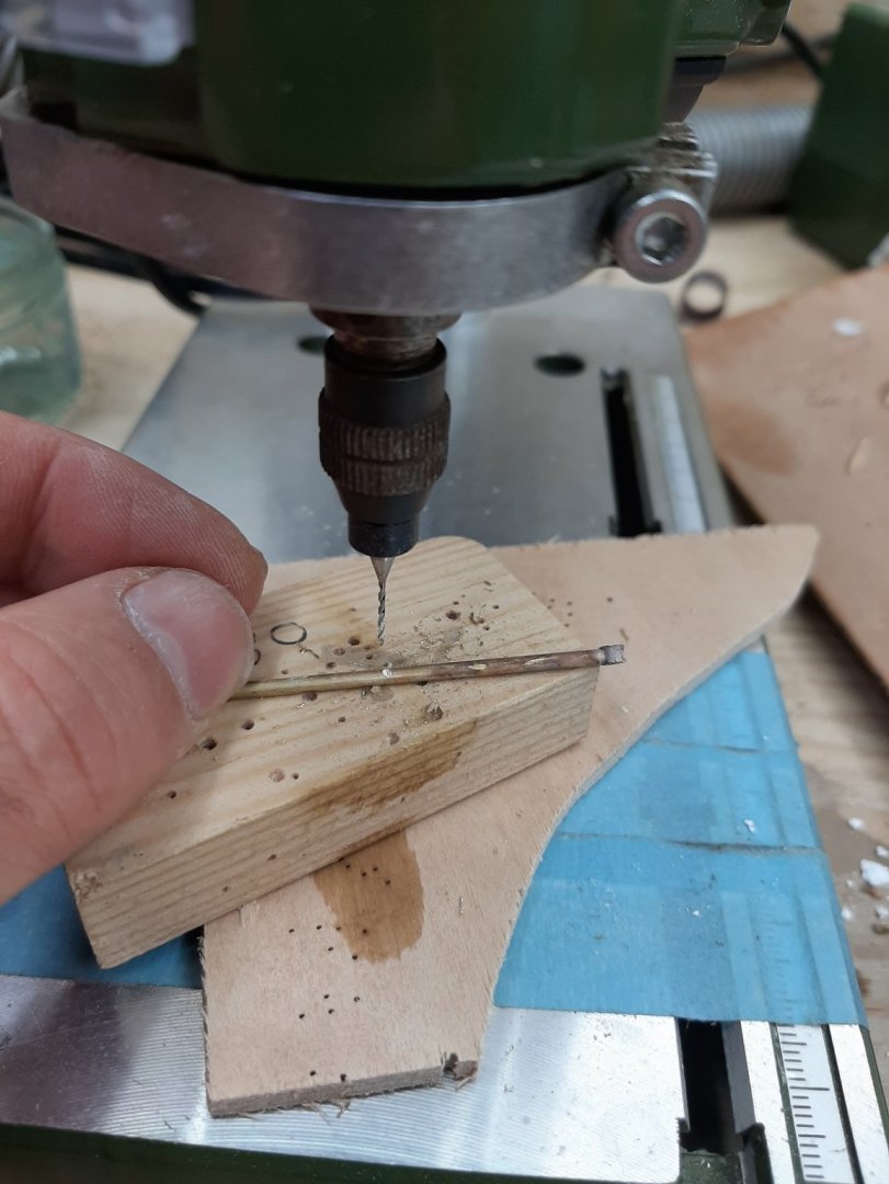
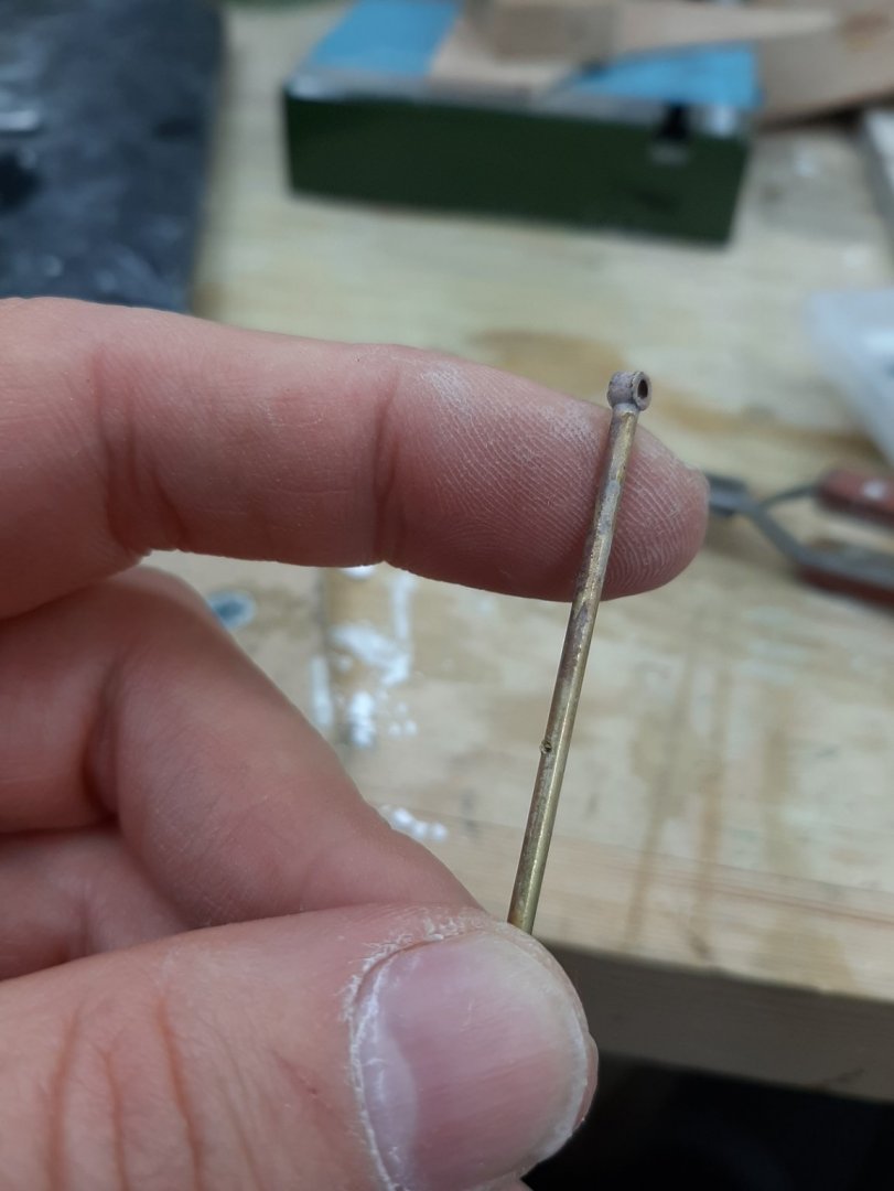
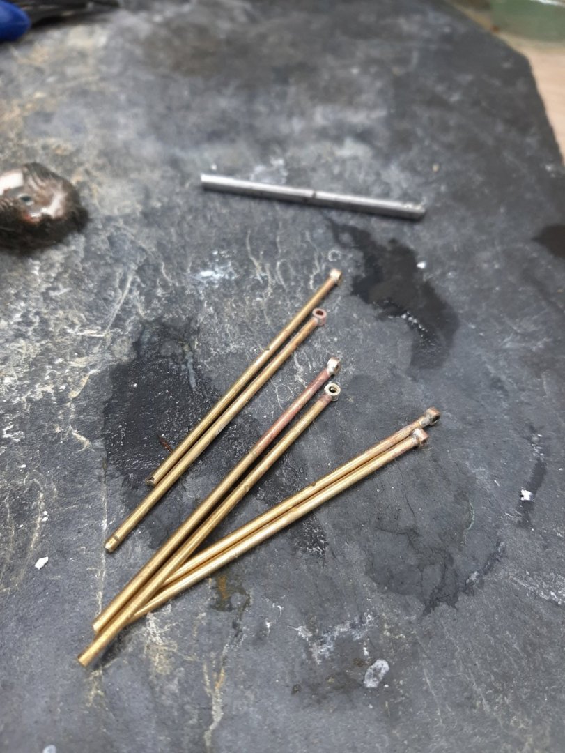
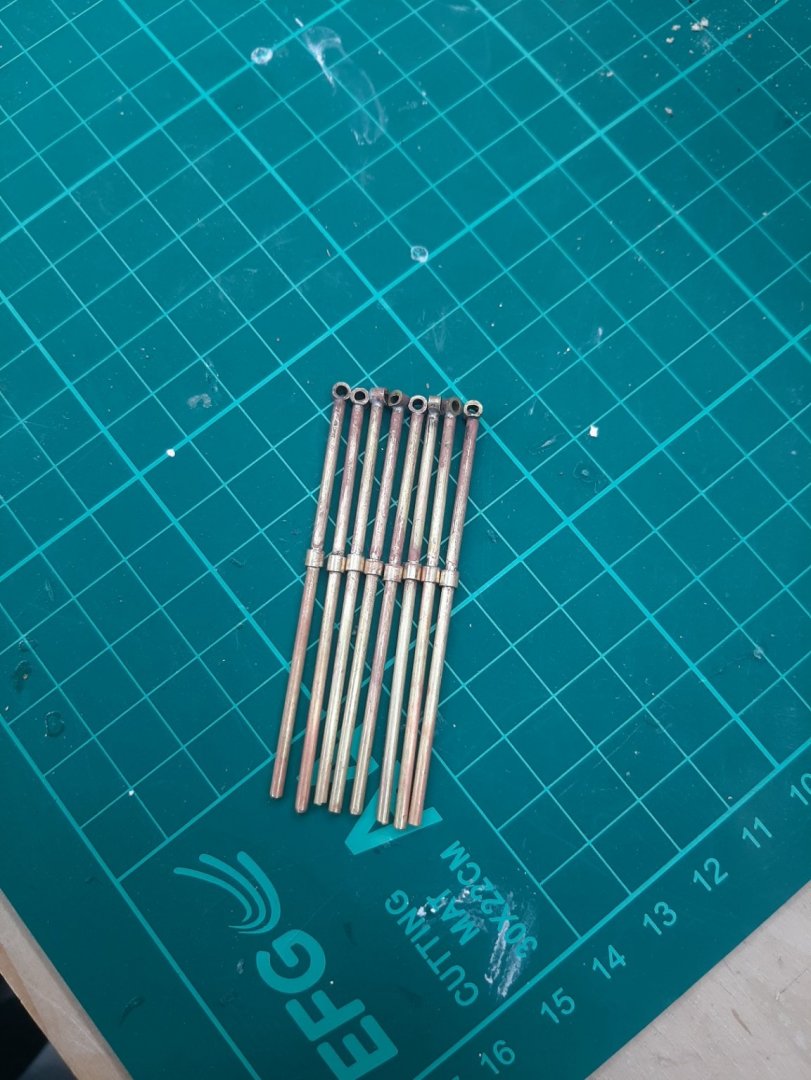
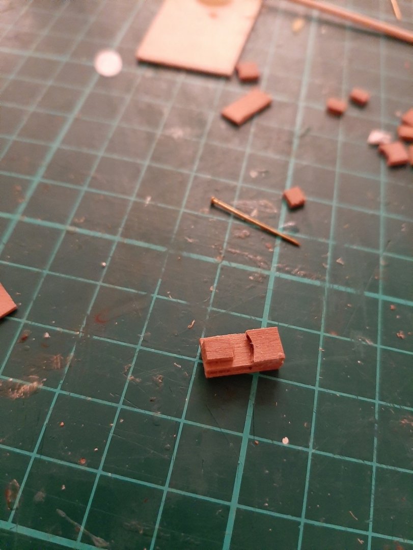
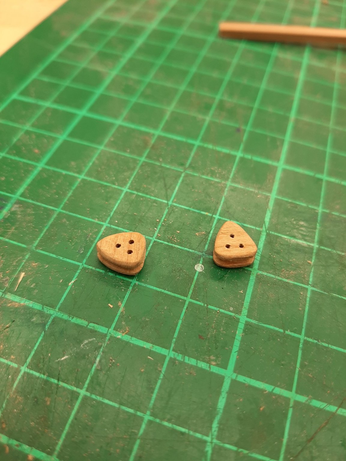
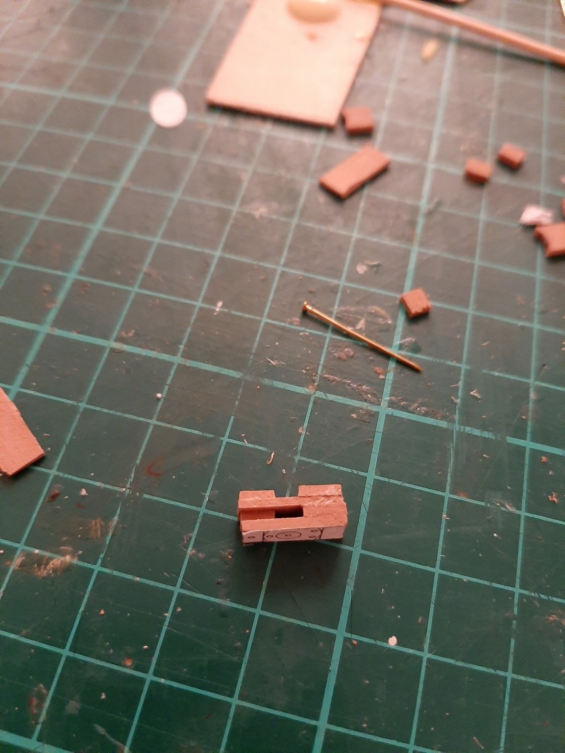
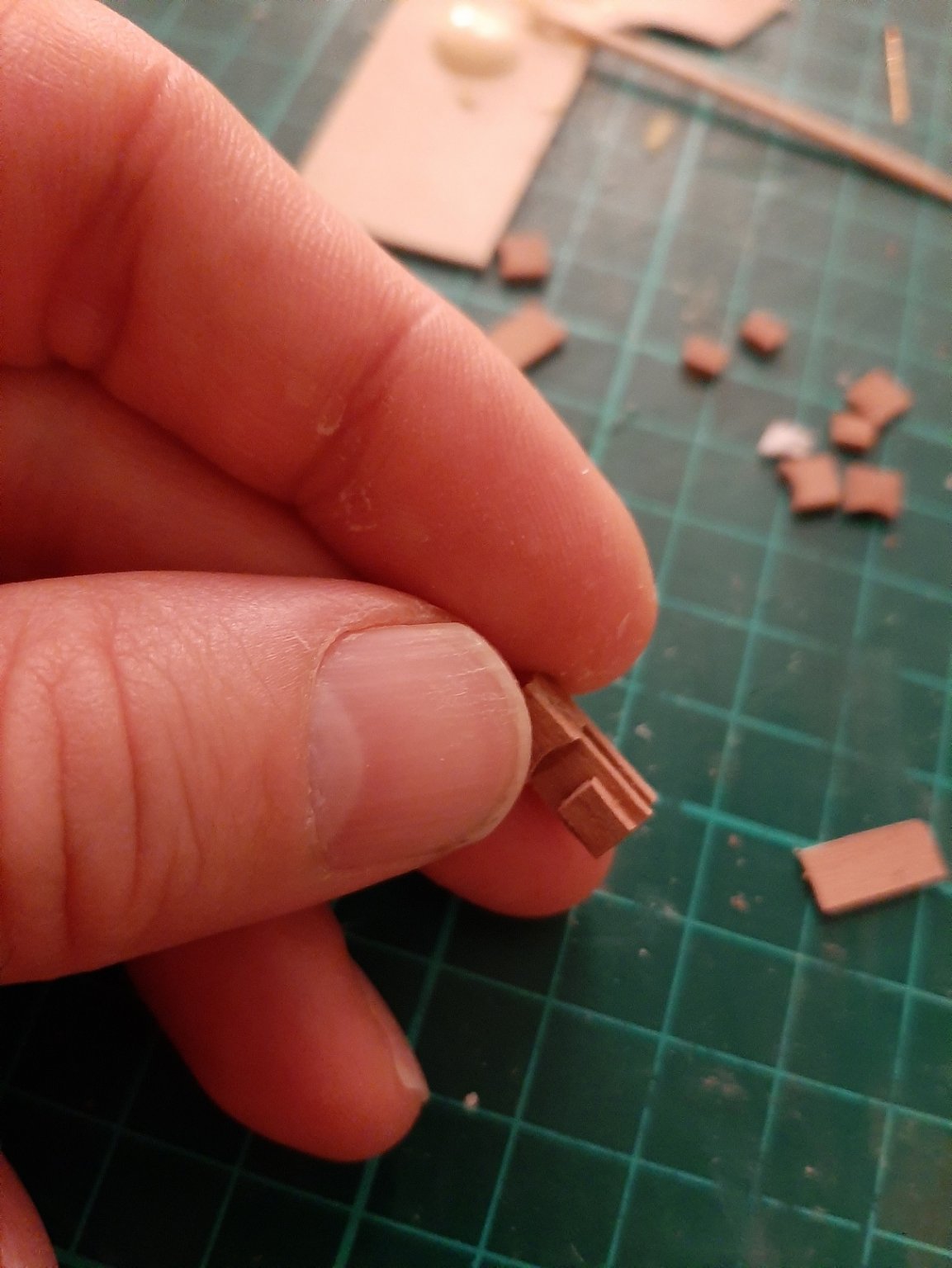
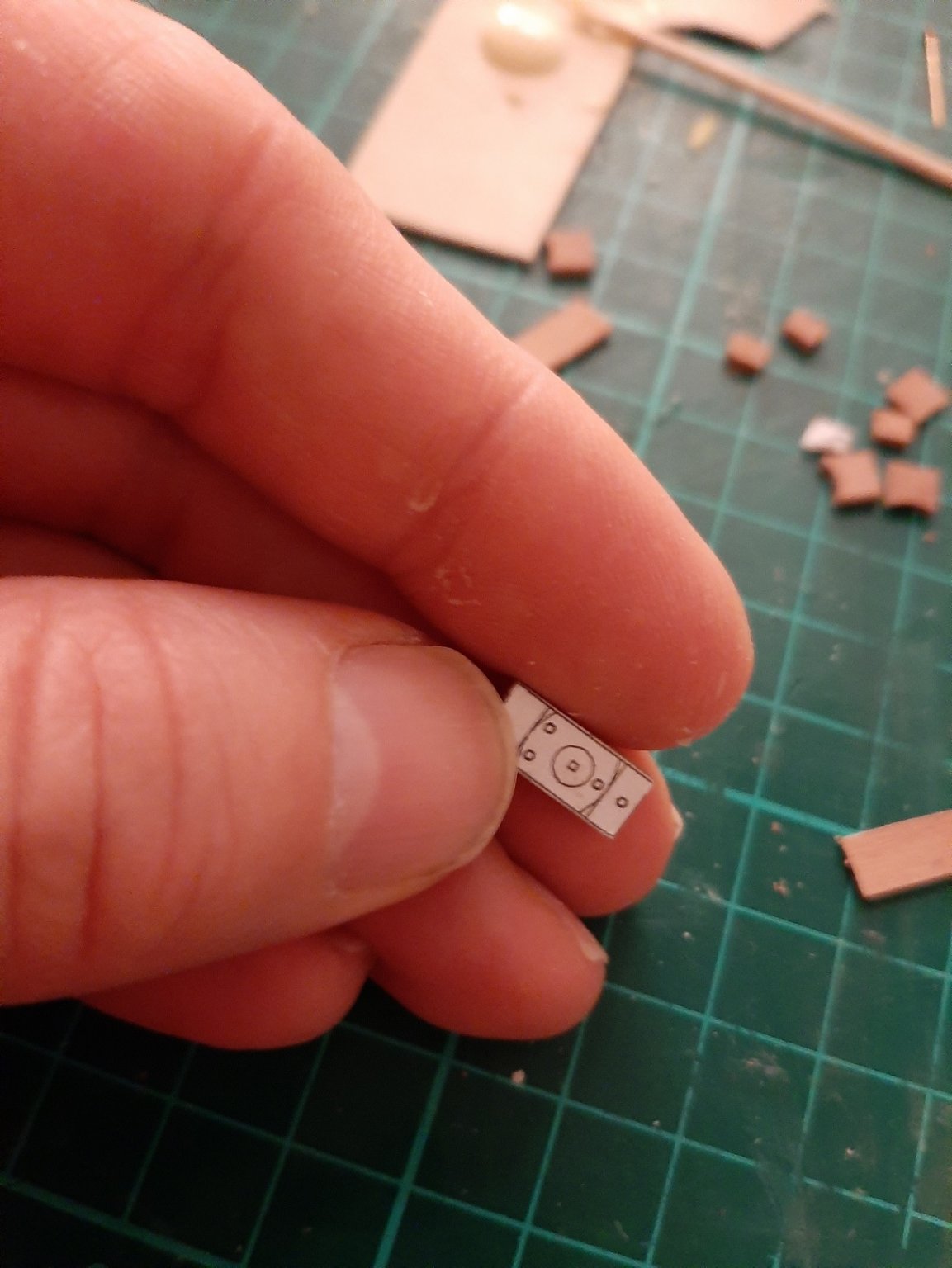
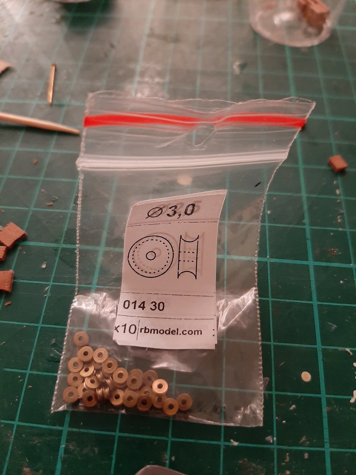
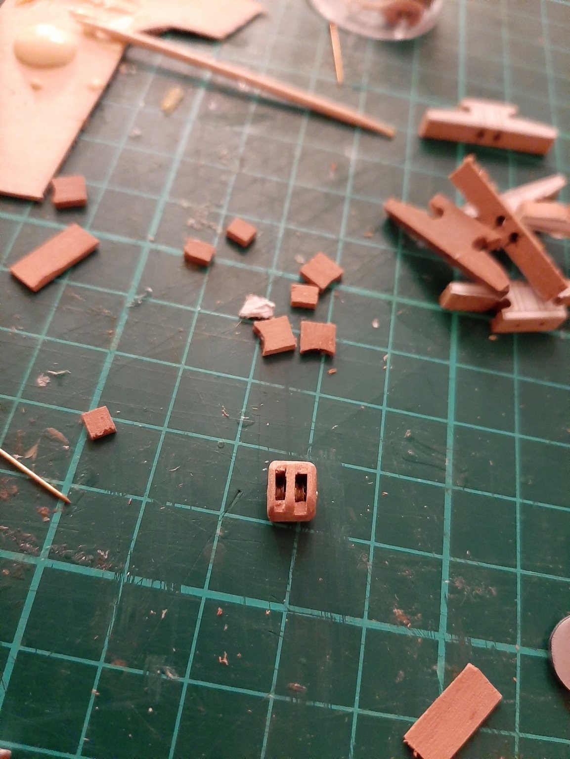
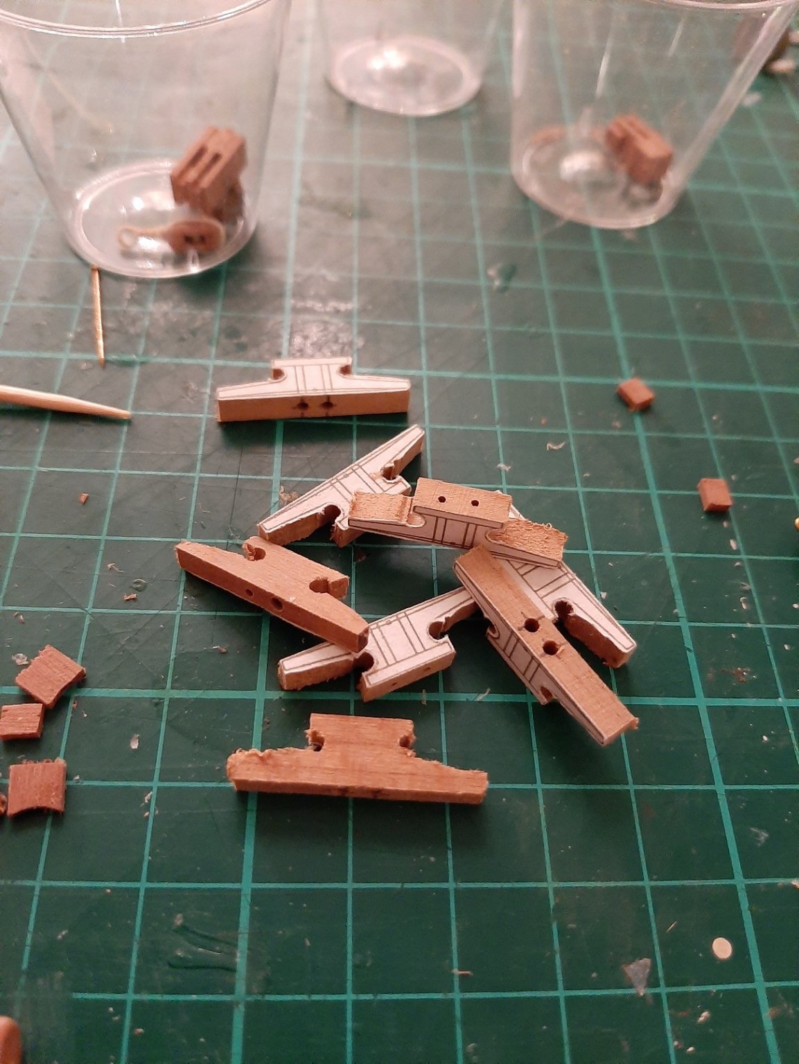
Many thanks to all for your likes and comments. Like many we are not allowed to leave the house so plenty of time to work on the boat! I ve made lots of blocks, many more than these in the picture. I hope they will be enough, making blocks is very complex and time consuming and I would not want to go back to it. I also made two hearts for tensioning the stay sail. I had to make them 4 times before I was finally happy. I then made some belaying pins. I do not want to buy wood at this time so I used whatever I had. I found a 3 mm dowel in my stash, I think it is Birch and used also toothpicks. It was a bit tricky to drill and then shape it but I used a wooden peg which worked very well. I then made the reefing comb, again fully functional with brass sheaves. I then finished and install the spreaders and then attached the 3 pairs of shrouds with shackles I then polished all my shackles. I think they will not be enough but making more is easy and relatively fast. In the end I used CA glue to secure the pin Now, to attach the shrouds and define their length, the mast needs to be up and somehow secure in place. I used scrap wood to secure it in place. I then made some templates from scrap plywood to hold the eyes in a fixed position The (dreadful) figure is 1.75 cm in height. It looks a bit out of scale, I think I ll need to recheck things. On the other hand the Deben is about 7 m long so it is not a big boat. There will be pin rails on the shrouds and I roughly checked the height the need to be placed at for a comfortable reach I will use black shrink tube as Michael suggested earlier in the log, I think it is a very elegant solution. I also got some fishing crimps which I cut to size and should give a very tidy result. However I need a heat gun which I ordered. So waiting for the gun to arrive, I started work on the rails. These proved very fiddly. I need 8 and after I had spent hours making them, I managed to ruin them all by carelessly drilling at random places for the second rope to go through and not parallel to the first rope I realised my mistake after I had marked or drilled all 8 pieces and run out of brass rod. Next day however, I thought of just soldering a piece over and re-drilling. There will be more pieces soldered to the base so I think in the end it will look fine This was good progress and I think I should be able to do a bit more work this week


-
Cargo should not have any issues, only people are not allowed to travel If you buy from Arkowood please feed back your experience, I was very happy previously but that was years ago Vaddoc
-
Welcome David, from the other side of the Atlantic!
-
This is just amazing. Getting those eyes done on the brass straps is a herculean act on its own.
-
Maybe just use thin brass or copper wire, served with thread around the block to look like rope, but bare beyond and blackened. A couple of turns will secure the wire/rope to the block
-
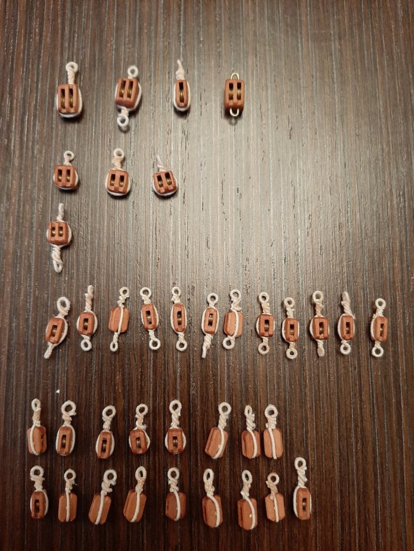
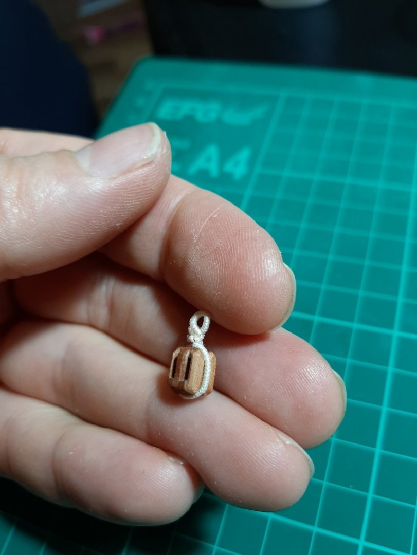
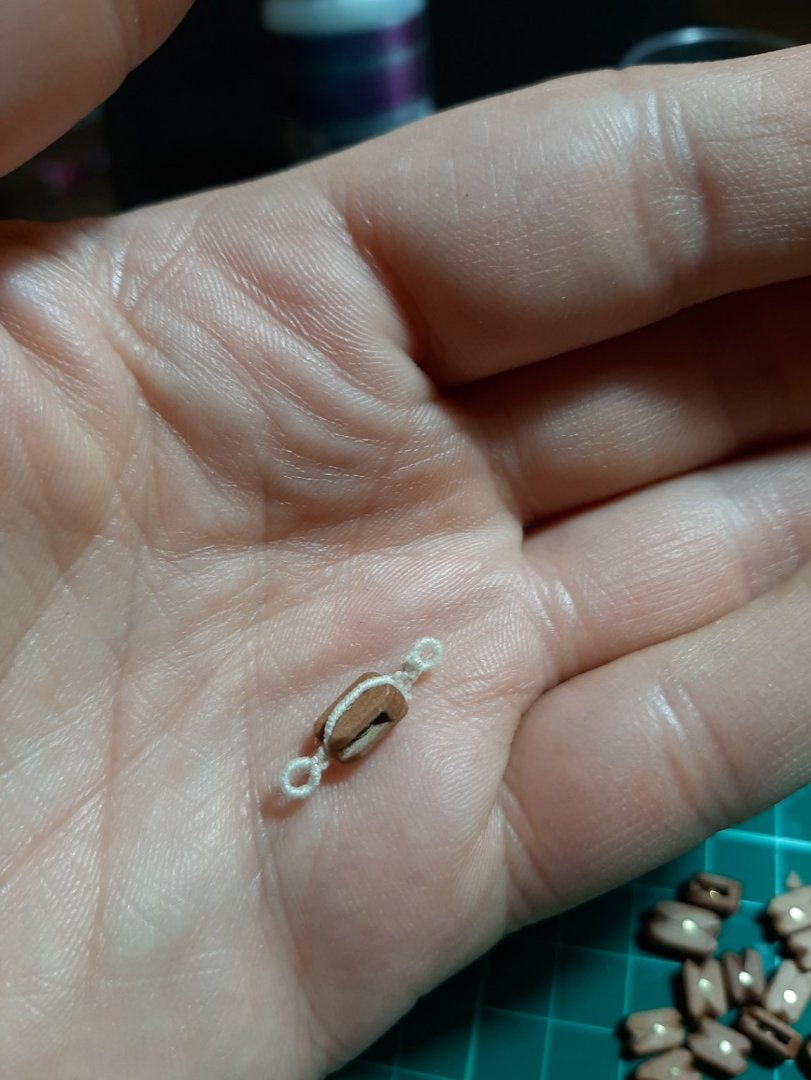
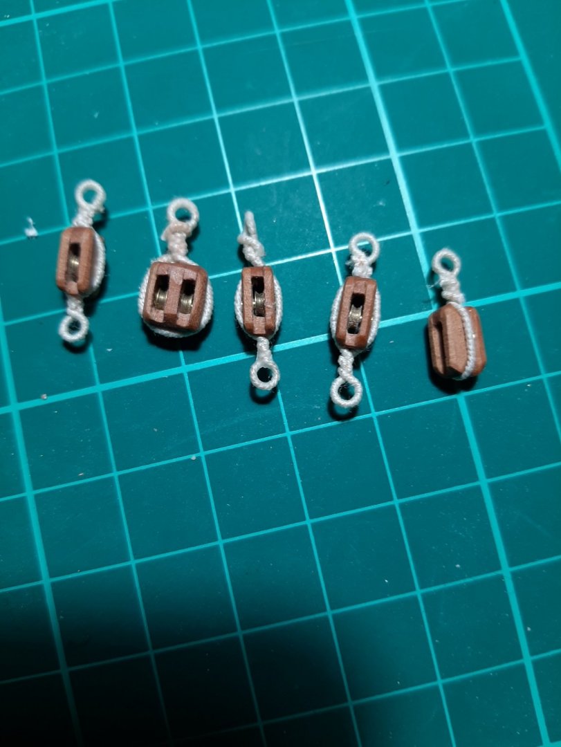
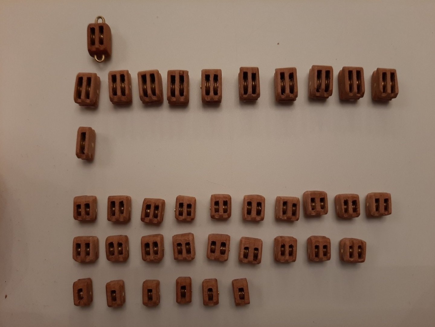
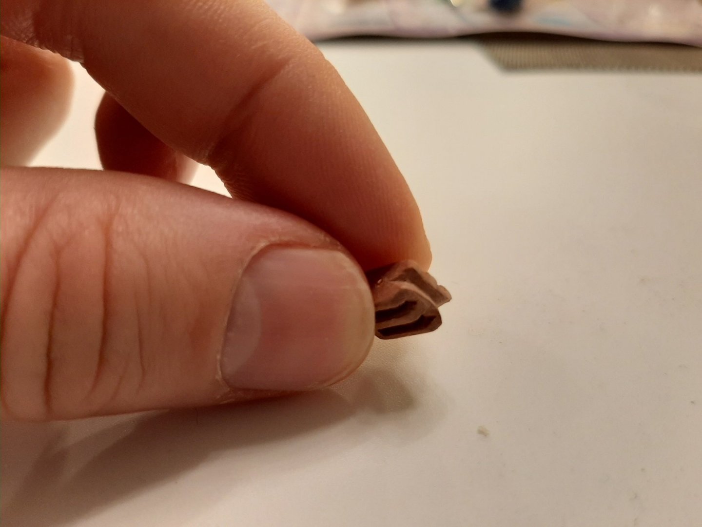
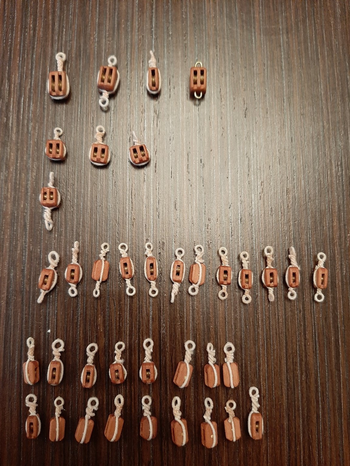
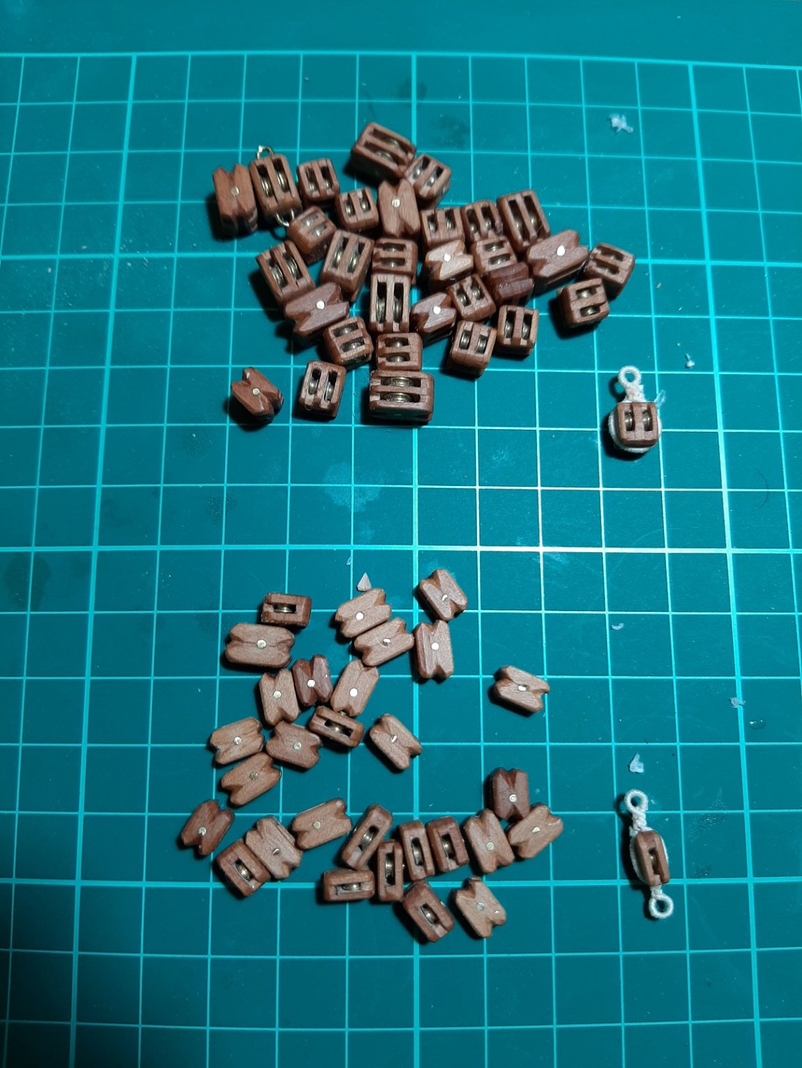
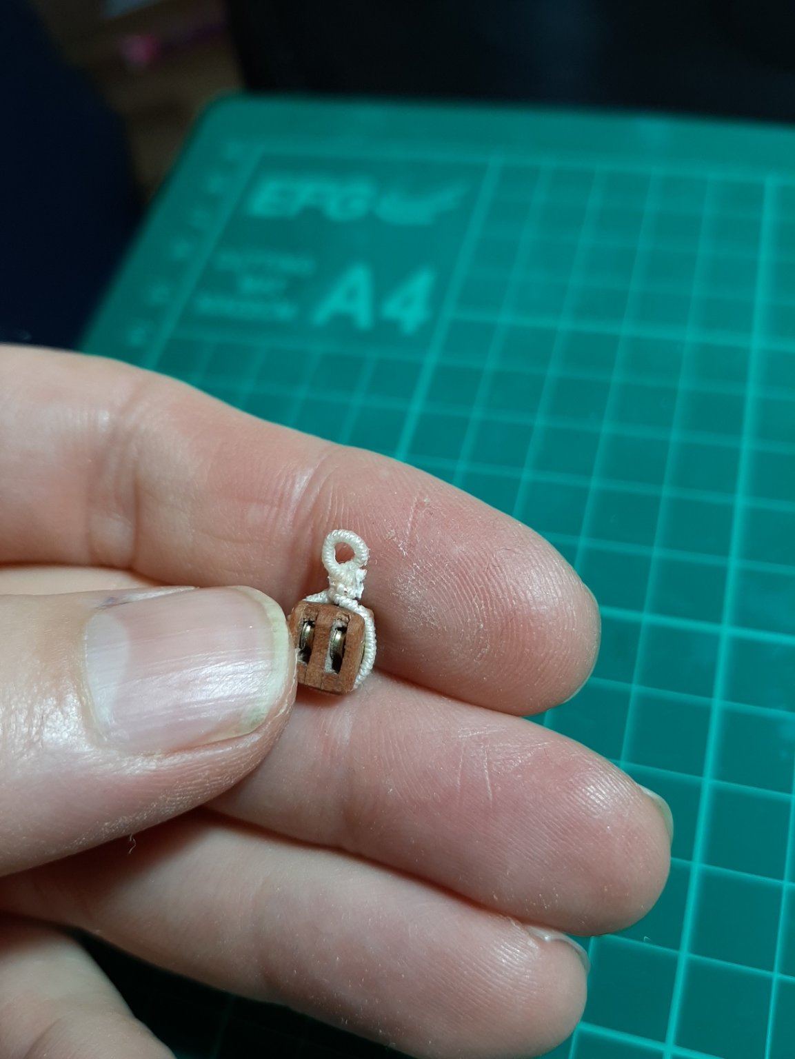
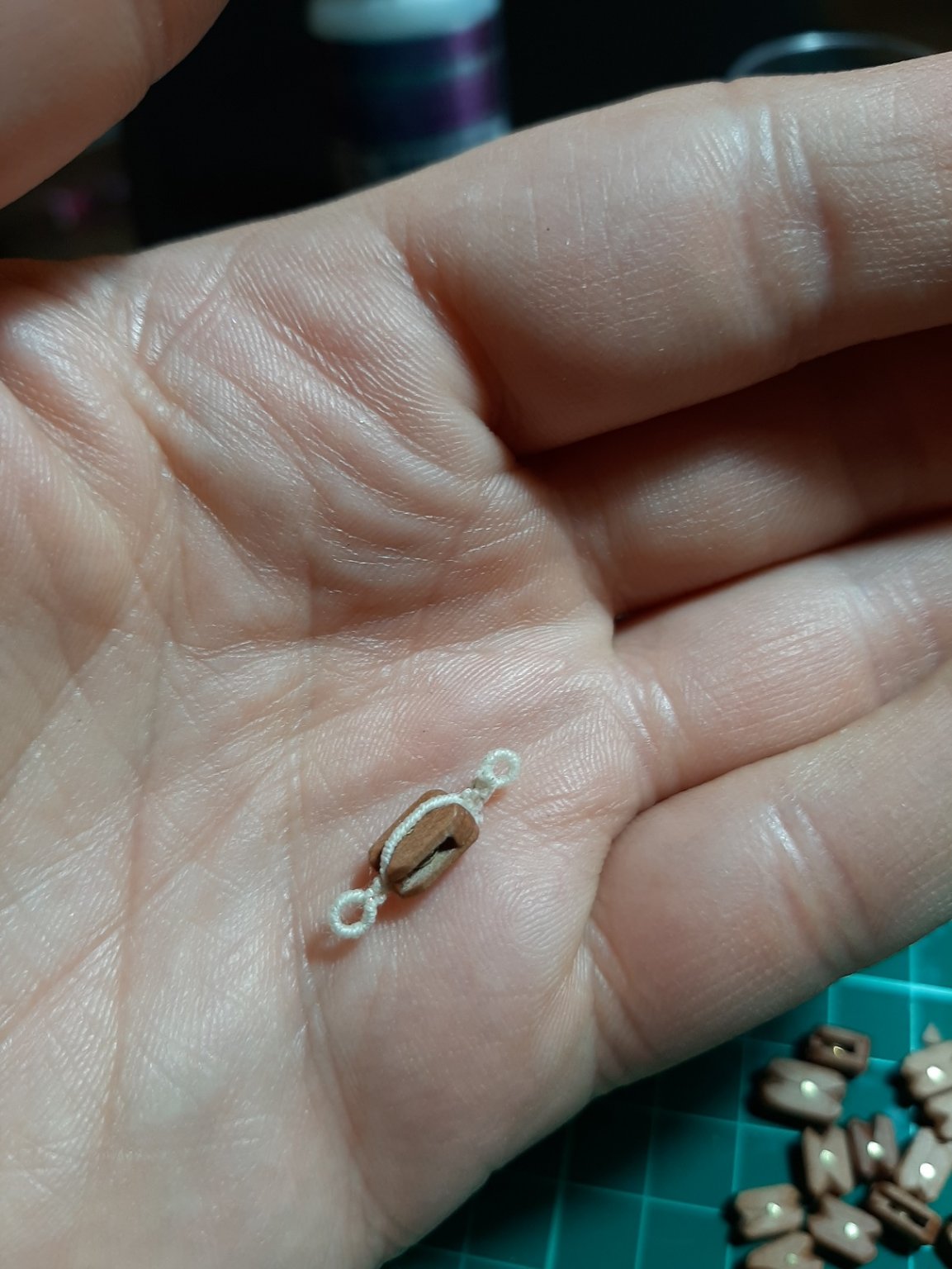
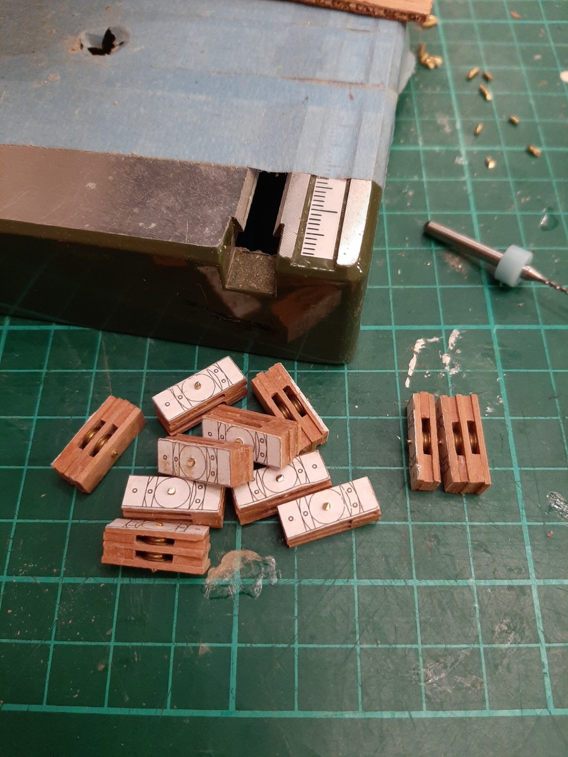
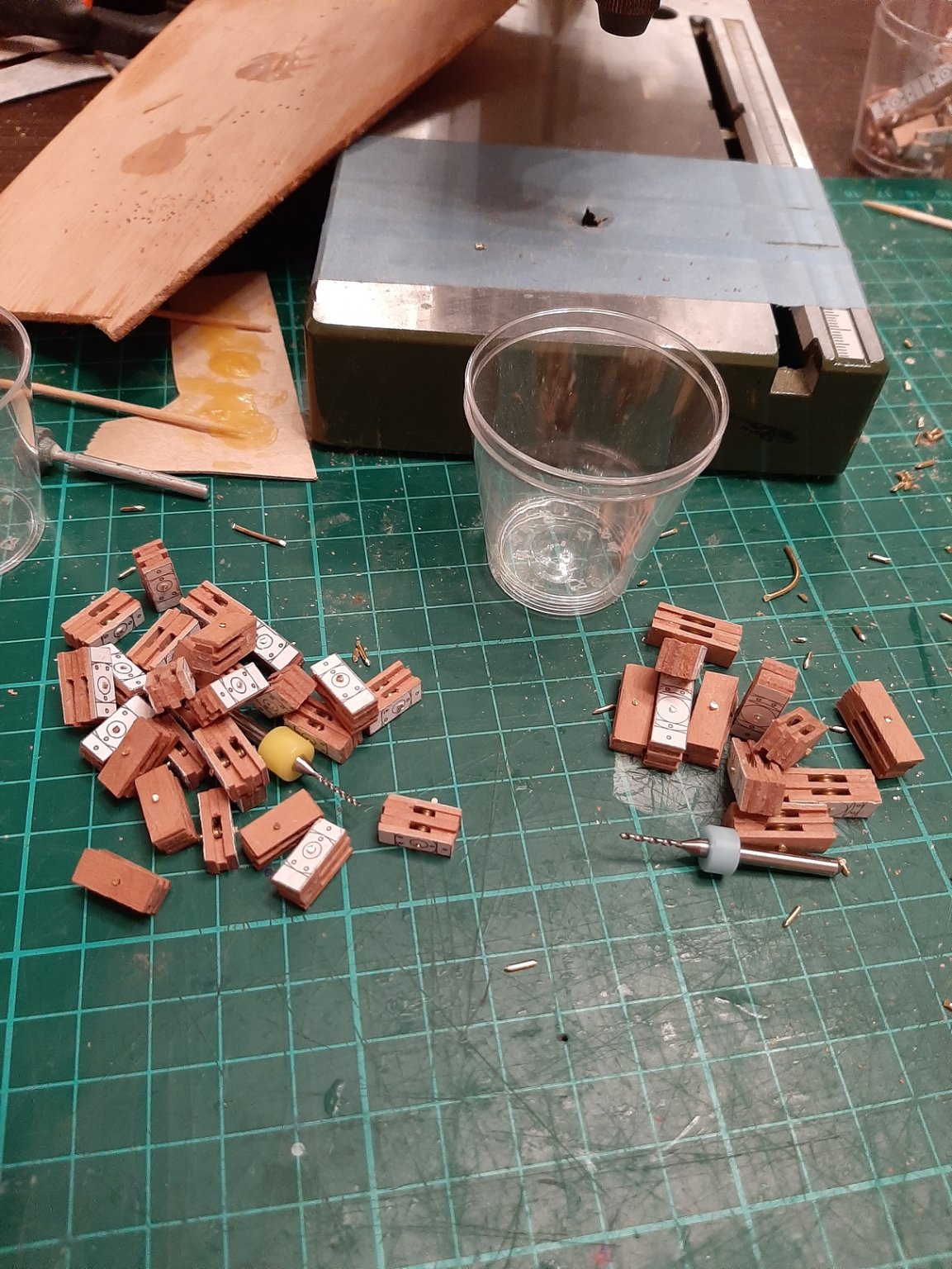
Dear all A small update, mainly to keep my log from going into complete hybernation. I finished the second bunch of blocks and then I put a coat of Tung oil on. They came out fine. Without Tung oil And oiled. The block that has the rope on is actually wrong as it is upside down so later on I had to redo it Making these blocks is really gigantic work but one that can be done at the sofa or the dining room table. I now have to attach the ropes. A few months ago I realised that copper wire served with white thread does a much better job imitating rope. I soaked the "rope" with CA glue to keep it from unravelling and to stiffen it up a bit.q A couple of close up photos, the first two show the block that was upside down. I now work 6 days a week + often doing a few bits and bobs on Sundays and with the kids and all there isn't really any time left. C'est la vie!


-
Wow GL, I have not been able to visit for a while but you have made good progress! Very nice joinery, nice fairing of the frames as well. Another thing you seem to have tackled with ease is the curvature of the deck beams-I struggled with this myself. Did the original boat have only one pair of stringers on the inside the frames? Vaddoc
-
Bench Top 5" Disk Sander
vaddoc replied to DocBlake's topic in Modeling tools and Workshop Equipment
I foresee these sanders achieving the same legend status as Paul Sellers' recommended chisel set! -
Bench Top 5" Disk Sander
vaddoc replied to DocBlake's topic in Modeling tools and Workshop Equipment
Great price for the Lidl disc sander. It is a bit small but for the price unbeatable. I made a disc sander years ago with a very old, much used corded drill, some thick plywood and timber. I used a £2 regulator for the speed and made the disc from MDF. I converted an arbor I bought cheaply. I chose a diameter of 200mm and I use 120 grit that lasts for ages. Perfect functionality It died after a few years of hard continuous use, I got another cheap drill and still going strong. I also sharpen the kitchen knives there! But for the price, definitely this sander makes a lot of sense. -
Bien venue Besson! Je ne pas parlez francais depuis 1986 mais ca est pas de probleme! Vraimant, ca est un forum charmant. Did my best Allan! Vaddoc
-
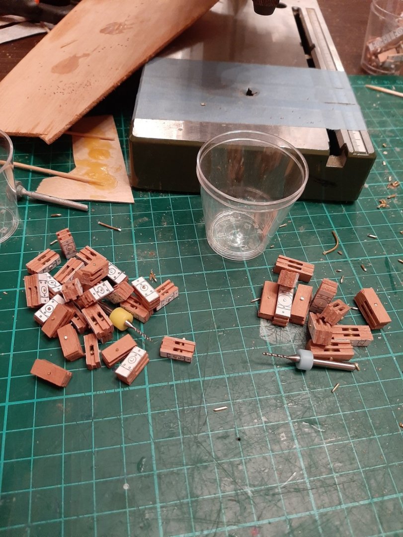
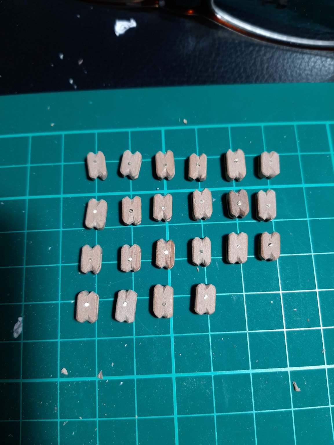
So, I did a massive amount of work and made quite a few blocks in 2 sizes. They are all fully functional with brass sheaves, they just need a coat of Tung oil and their ropes. However, a lot of this work has actually gone to waste, at least for this boat! The reason is that I thought I would need mostly double blocks. Today, I started drawing the rigging arrangements, each part individually and noting the blocks that would be needed. They are mostly single blocks and a lot of them! That means another 2-3 weeks of work on the dining room table... Another issue that I am not sure how I will overcome is that there will be an amazing number of rope ends to be tied somewhere, a cleat, belaying pin or other. Either I will need to add belaying pin rails to the shrouds (if feasible as the middle one due to the spreaders is offset) or a rail on the cabin top. I will of course also need to pepper the boat with cleats. I think the end of this journey may not be that far!
- 536 replies
-
- 11
-

-
I do Bob, but my models are large and do not live in a case but are temporarily-permanently stored wherever there is space and are moved. I know, not good, in good time this will change. Also, the hull is the first to make and paint and then on it will take years to finish the rest so the hull will have a hard life tilting, scratching and bumping all over the place. I have an old model that had the hardest of lives, spent his life in shelves under direct sunlight constantly falling of its flimsy base, hull is 0.8 mm plywood with automotive primer, humbrol acrylic spray and humbrol enamel varnish on top. Still looks good! I d say Moab, just use the thinner the company offers. Cheap and much better than homemade ones or pure water.
-
Acrylic paint is not tough at all and needs some protective finish. Humbrol gloss varnish is great and can be brushed (on cured acrylics also) with great results but is enamel based. A few years ago I tried Valejo water based acrylic varnishes but could not make them work. At the time I also tried the Valejo polyurethane varnish which I did not like. However, I tried the newer Valejo polyurethane varnish which are different and improved and this time I had very good results with a brush. I could not find any info though whether it should be diluted and what with. I think in the end my conclusion was to use water but not too much otherwise it breaks down. Application is the same as the paint but the self levelling properties are even better than the acrylic paint! I think 2 coats 4 hours apart or something similar. I also think they claim it will not yellow over time. The matt varnish needs very thorough stirring and quick application afterwards with minimal brushing and even then the matt particles might spread unevenly leaving brush-like marks. Still, enamel varnishes are much tougher
-
Just to add regarding the arrangement of planks at the stem, that is being placed as high as possible. There might be a connection with the issue of the "exaggerated sheer" (I think this is the term) It is possible when designing a boat, although the sheer is fair and appropriately curved, when the actual boat is finally built, the sheer to appear flat at the bow. This is just an optical illusion due to the size and flatness of the boat and to avoid this, it is recommended to increase the curvature of the sheer at the bow, thus having an "exaggerated sheer". Maybe this is why these people suggest to push the fore end of the planks higher, to get a more pleasing run of the planks.
-
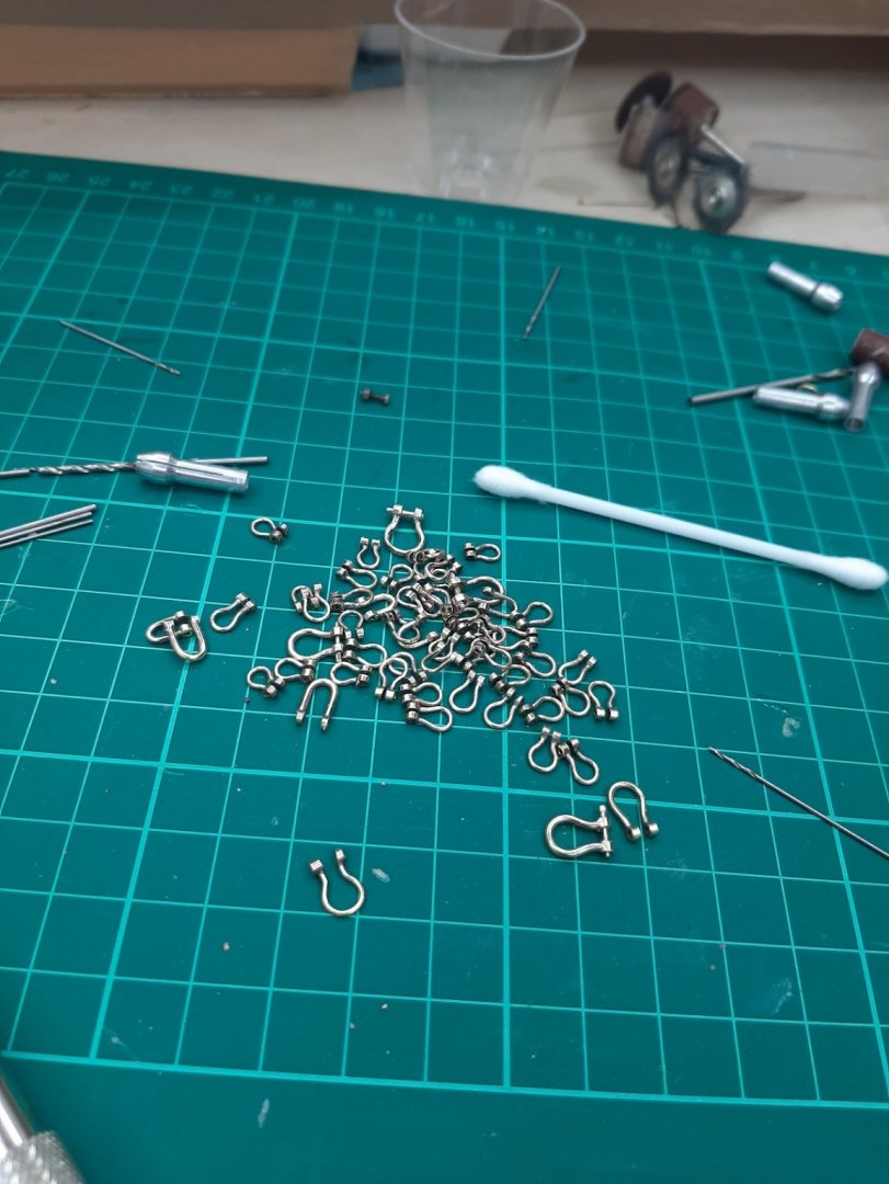
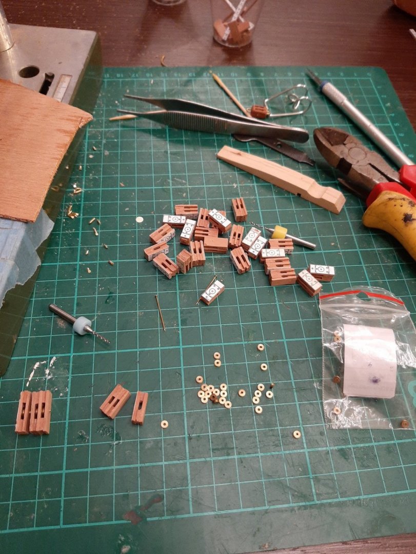
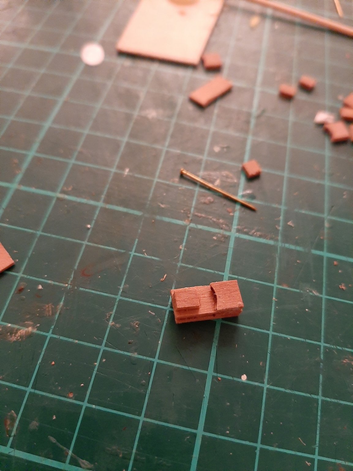
So, back to work on the Deben! I think I should be alright having made close to 80 shackles, but I will need also blocks. I had decided from the beginning that all blocks would be fully operational with brass pulleys. I need to make many and they take a very long time to make! I am making them pretty much as the full scale ones are made and really they are complex pieces. I ve made 40 that still need sanding to dimensions and to shape, grooves cutting, Tung oil and then the ropes attached. I think I ll need maybe another 30, huge work for something that no one will ever suspect is there! A few photos:


- 536 replies
-
- 11
-
-
Apologies for the delay in replying, life went again into hyperdrive Dan, this is a lovely model! What did you use for the iron nails holding the planks together at the lapstrake? Will do, bellow is a relevant nice pic from the Deben: Now, I would ordinarily agree with you. However, the following made me think that this may not always apply: 1. Playing with the CAD, changing the height of the garboard had a massive effect on the plank shape, straightening some and making others more bent in a very unpredictable way. 2. On Youtube, there is a great series of videos on how to line off and build small boats, look under "traditional maritime skills, lining off planks (small boats)". On part No 4, the builder is commenting that the garboard seems to come up too low on the stem and he needs to change it so all the planks will be pushed up. 3. I am currently reading (very slowly!) "Lapstrake boatbuilding" by Walter J Simmons. In page 65 he writes: "...bear in mind that the whole planking job will go easier and look better if you allow the hood ends of the garboard to rise as high as possible, A narrow garboard is easier to fit, but one that is wider fore and aft will result in straighter subsequent planks and will thus make the remainder of the planking job easier" I can tell you that indeed, in the yawl, pushing the fore end of the planks higher up the stem resulted in a more pleasing run of the planks. This does not apply planking a big ship, as the garboard really needs to be kept very low at the stem to minimise crowding of the planks and the use of stealers. Only way to tell is to build the thing! All in good time... Tony this is the easiest thing to do. You just select the curved surface and you press "unroll". The computer thinks things over a tiny second and gives you your surface flat! I would not rely on CAD to get the shape of the planks, it is immensely difficult to establish it. However, this is how I calculate the wood I should need for this boat: I expect I will have 3-4 planks each side quite curved and the rest more or less straight. So each 100 mm wide sheet should give me 2 curved planks and perhaps 4 reasonably straight ones. So if I end up with 15 planks each side, I ll need 4+6 sheets and with a 50% margin for error and wood selection, 15 sheets of beech 2 mm. This is close to £60 without shipping! On another note, my computer suffered some catastrophic damage and packed up. I also managed to drop my laptop, it took a bend and I had to straighten some areas with pliers but still works just fine. I ordered a new desktop which should arrive in 2-3 weeks. I also took the opportunity to get a new monitor, chair, lamp as well as some peripherals. Although it is nice to get new toys, it takes a lot of work to set up a new computer and right now it is the last thing I wanted to do. Still, it has to be done! An opportunity to go back to the Deben which at some point needs to leave the shipyard to make room for the Yawl! Regards vaddoc
-
Workshop Essentials - Favorite Features
vaddoc replied to Justin P.'s topic in Modeling tools and Workshop Equipment
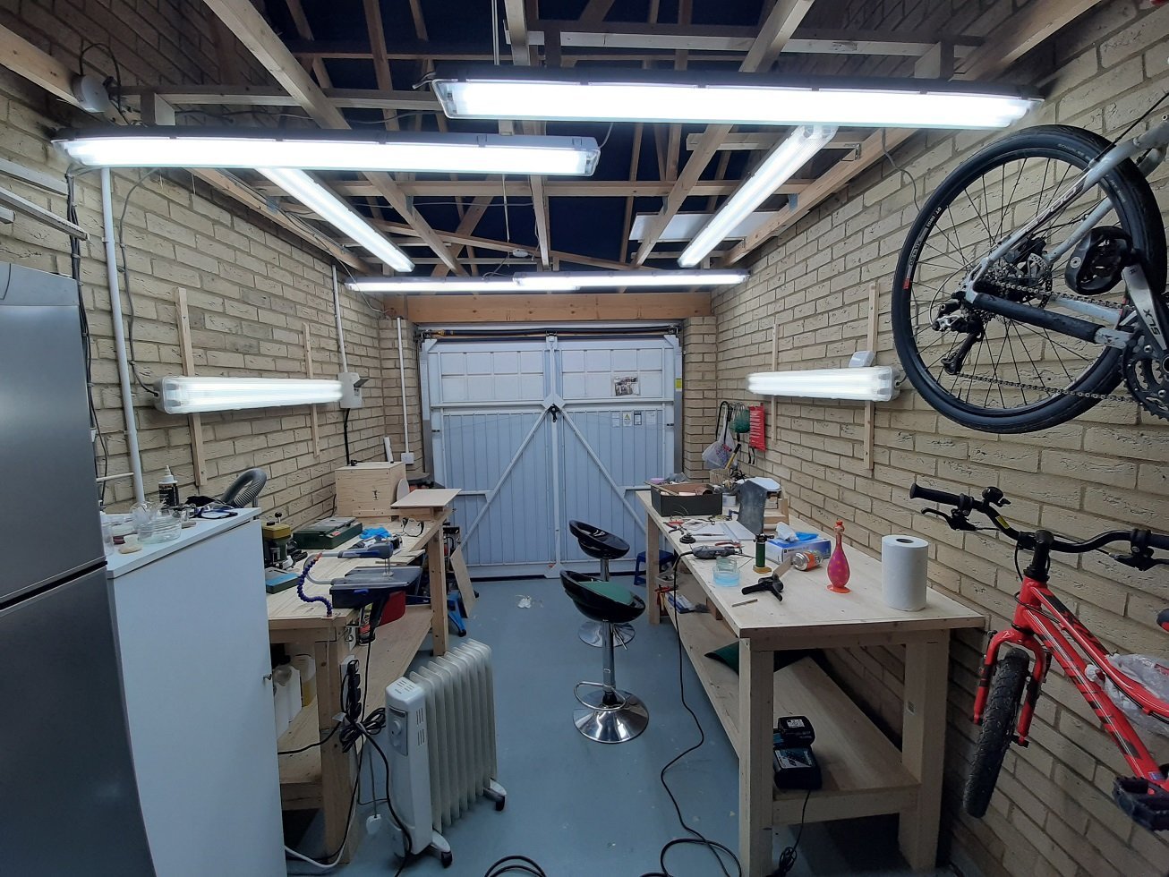
I have a single detached garage, not insulated and this is what worked for me: 1. I built from cheap wood two very heavy solid work benches. I followed the advice from this chap's video on you tube. Great benches, very cheap to make https://www.youtube.com/watch?v=JTxbcf9zI5o. I chose how tall, wide and long so entirely custom made to my needs. This is by far the most solid design I have come across. 2. I did not bother with insulation, I got a gas heater which heats up the space quickly. This way I do not use the limited power supply and considering the limited time I have to work and that near zero temperatures are not too often, it makes perfect financial sense. 3. I chose not to paint the brick walls but instead put a lot of lights, more than twice than what I initially thought (about 1000w fluorescent light for a space 5 x 3 m). Very important to have light coming from all directions to avoid shadows. You can never have enough light! Each has its own very unique set up but the issues above occupied much of my time and successfully I avoided the very expensive complex options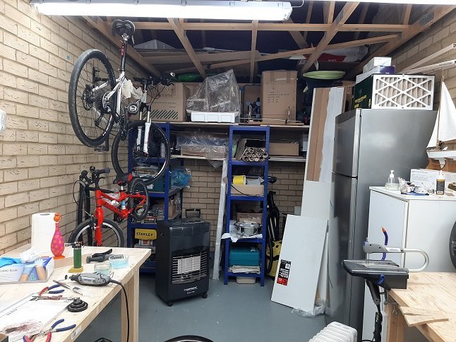
-
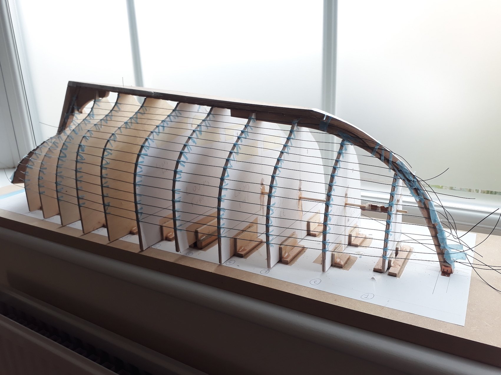
Thanks GL, It is interesting to see that the run of the planks is reasonable. The planking is not correct though and when the real boat is planked, the following changes will be needed: 1. The garboard should come higher up the bow, this will push the planks higher and maybe reduce the curvature of the planks 2. The width of the planks at the really curved areas of the hull and at the transom is far too much. This needs to be reduced and width gained at the flat areas. 3. I think 11 planks are too few, the average width is around 13 cm which is probably far too much. I suspect it will end up with 15 planks each side 4. There will be a 2 mm overlap for the lapstrake. Due to the large scale, it is possible to do the planking exactly as it would be done in the full scale boat. The challenge will be access to the keel/planks, I was thinking of using a similar jig to yours but some modification will be needed. Vaddoc
-
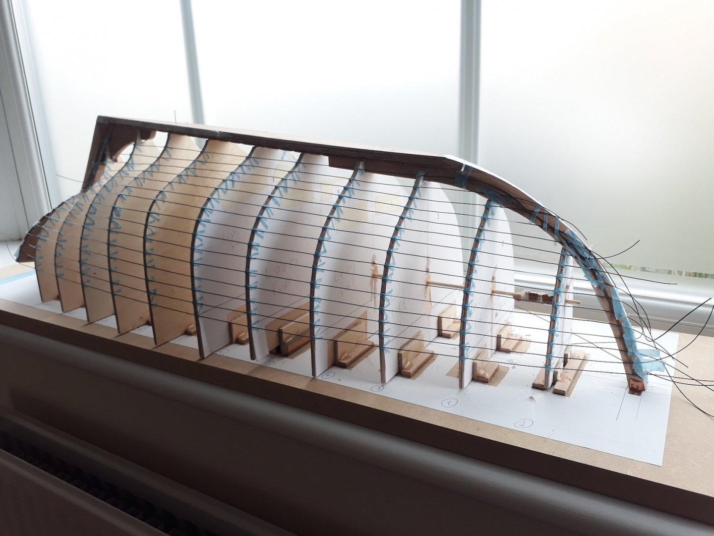
Many thanks to all for your very interesting comments! Now, I feel I may have actually managed to more or less define the shape of the planks. It has taken me overall many weeks of trial and error but this time the run of the planks looks ok. It is so much more difficult to do it with CAD, there were times that I thought of just cutting the frames out in cardboard just to be able to lay a batten! I fully admit it is a bit silly to do this on the computer but I am afraid it will be quite some time before I can cut wood and I really wanted to take it further and see the shape of the planks. Now, this is the carvel planking but the lapstrake will come out using the same lines. It is not perfect but I think it is pretty close. The largest blank needed is 57 cm, this would need either a crooked tree or a scarfed plank. Regards Vaddoc
.thumb.png.6e20072b44acacfd8aacf8f7143588b4.png)
.thumb.png.fd0964cfb845ccc2350735cb36a4352a.png)
.thumb.png.da9e53410d19c5591f5ceb27bcaa67b0.png)
.thumb.png.211fd39144c294bae8fe142ca0ed06d8.png)
-
All so very true! Fairing lines is so easy with CAD but at the same time feels very artificial and indeed, the result is a compromise and seems that the computer is making decisions on its own. Much better to use a batten! Building boats I find myself wearing two hats. One is the CAD hat, when I am trying to make all drawings perfect. Then the modellers hat, where I find challenging to even make all frames have the same height. In the Deben the tolerances between the CAD drawings and the actual result were abysmal, some frames were out of alignment by 2 mm and I did not like the lines at the bow so I let the wood sit at the angle it liked to sit and readjusted the frame to the new lines. No problem at all in the end! Indeed some degree of lofting is needed to make sure lines are reasonable close and fair but thankfully the wood has its own self-fairing properties. On a different note, I suddenly thought of another way to tackle the Yawl's planking which may work this time. I will try it when I have the time as I would like to have some idea of the shape of the planks. It will be a CAD exercise of course but I do not have any time to create actual wood dust so a good substitute for now. This is another side of things, CAD gives you the satisfaction of creating the boat although virtually. We do of course have our own CAD building section!
-
Many thanks for the offer Keith! Considering how slow I now work, it makes sense to get even very expensive wood orders as the cost spreads over many years. But it seems very attractive to get a plank and mill it. These would open up a whole new range of options. How do you do mill your wood, do you have a professional set up or a more scale down one for example with a proxxon or Byrnes saw?
-
No worries at all Bob, your advice was very well taken! I consider my hugely underpower proxxon KS 230 table saw the most dangerous tool I own.


.png.45ba2a0528d093a2a486457c5deebaef.png)
.png.8cb9c11f281511c94f3dff589934a29b.png)
.png.706905c5ab70fdb233cfb0f94561600c.png)
.png.e3a81025895a78ec5de887941842885e.png)