

.jpg.f26acc9a74319261612561bfa7da1303.jpg)
vaddoc
-
Posts
1,580 -
Joined
-
Last visited
Content Type
Profiles
Forums
Gallery
Events
Posts posted by vaddoc
-
-
Progress has been very slow recently as I am really struggling with the keel, the bevel it should have and the shape of the bottom panel.
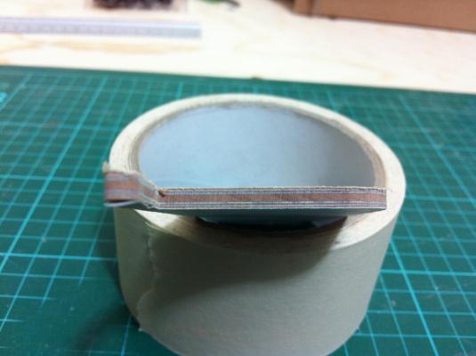
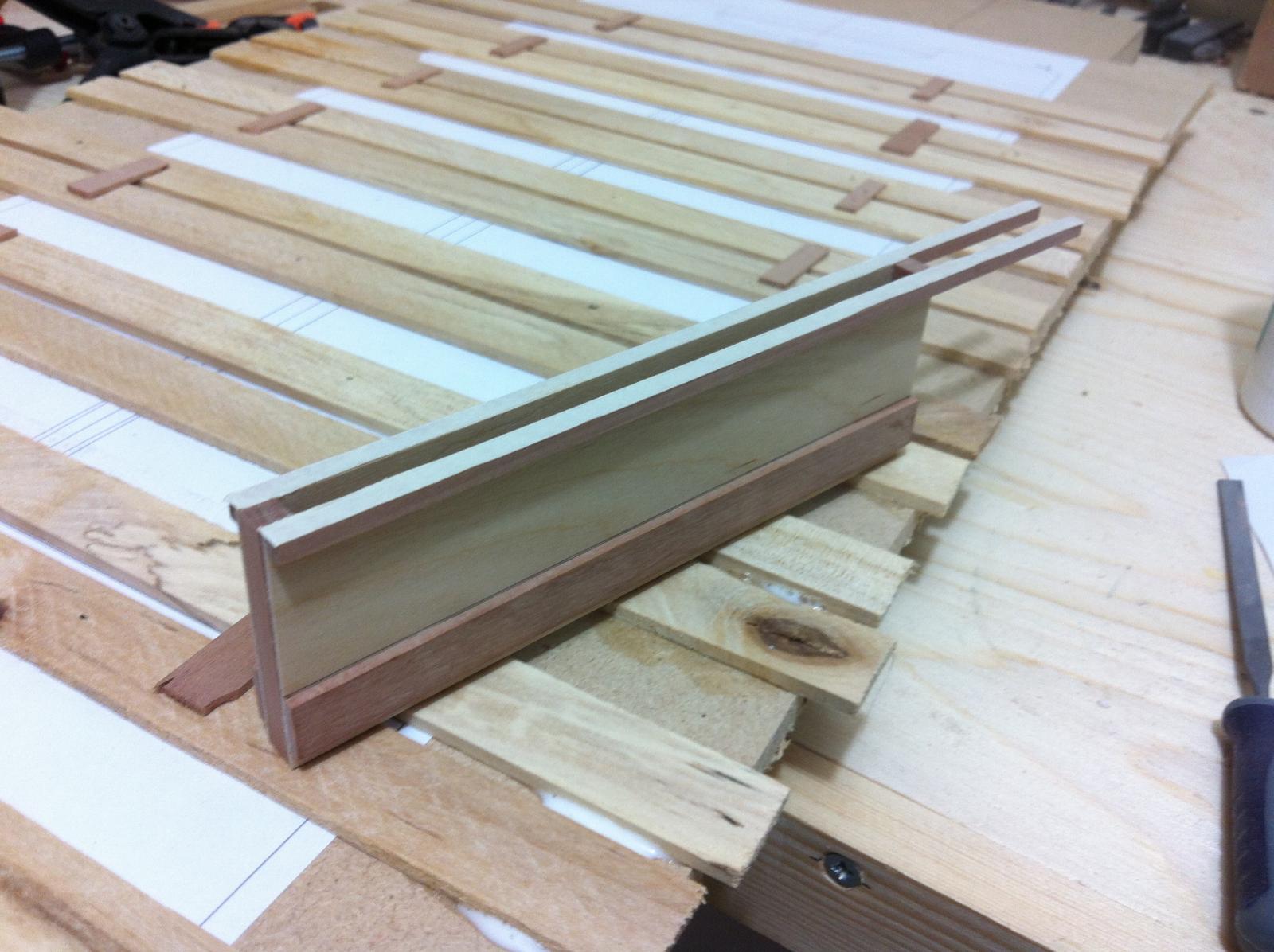
I finished the CB case and installed it.

I first used epoxy to glue the case to the frames. I tried packing the case but it distorted the frames. I was very careful with the epoxy as it is a very messy glue.
I also added the outer clamps and glued the stem to frame No 1
I then reinforced the CB case with epoxy filets. It looks a bit messy but all these will be covered by the floor boards.

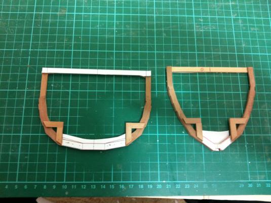
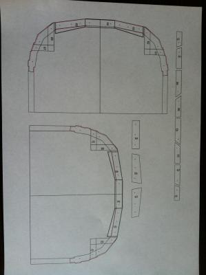
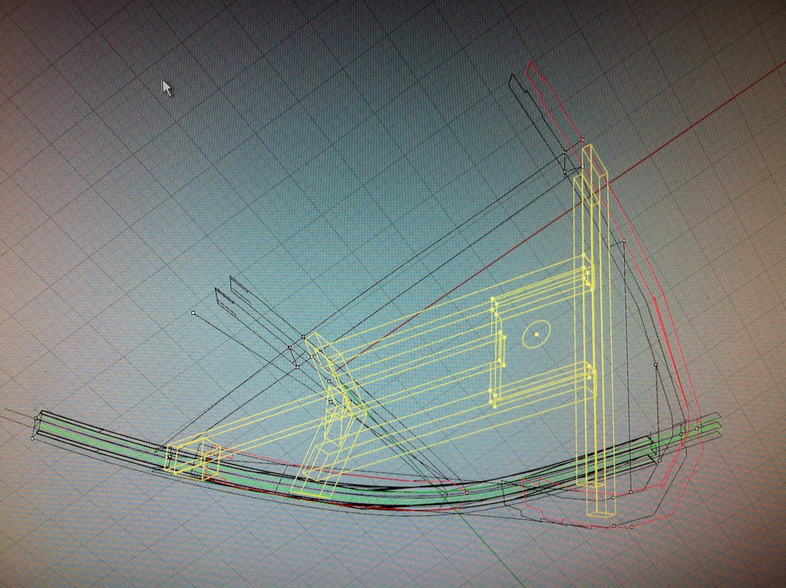
In my CAD plans I designed the bottom panels but did not take into account that the rabbet line is not straight but widens at the centerboard. Also, the panels need a lot of bevelling where they meet the next panel towards the sheer. Overall I still have not pinned down the right shape.
I have lined how much I think needs to be removed
I attached the outer clamps to the stem

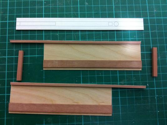
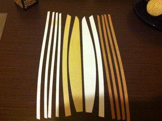
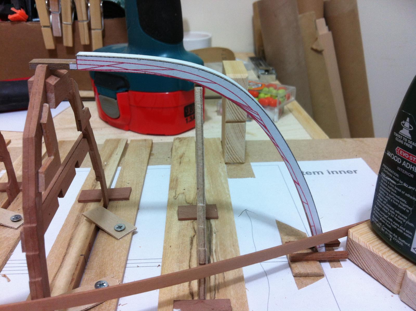
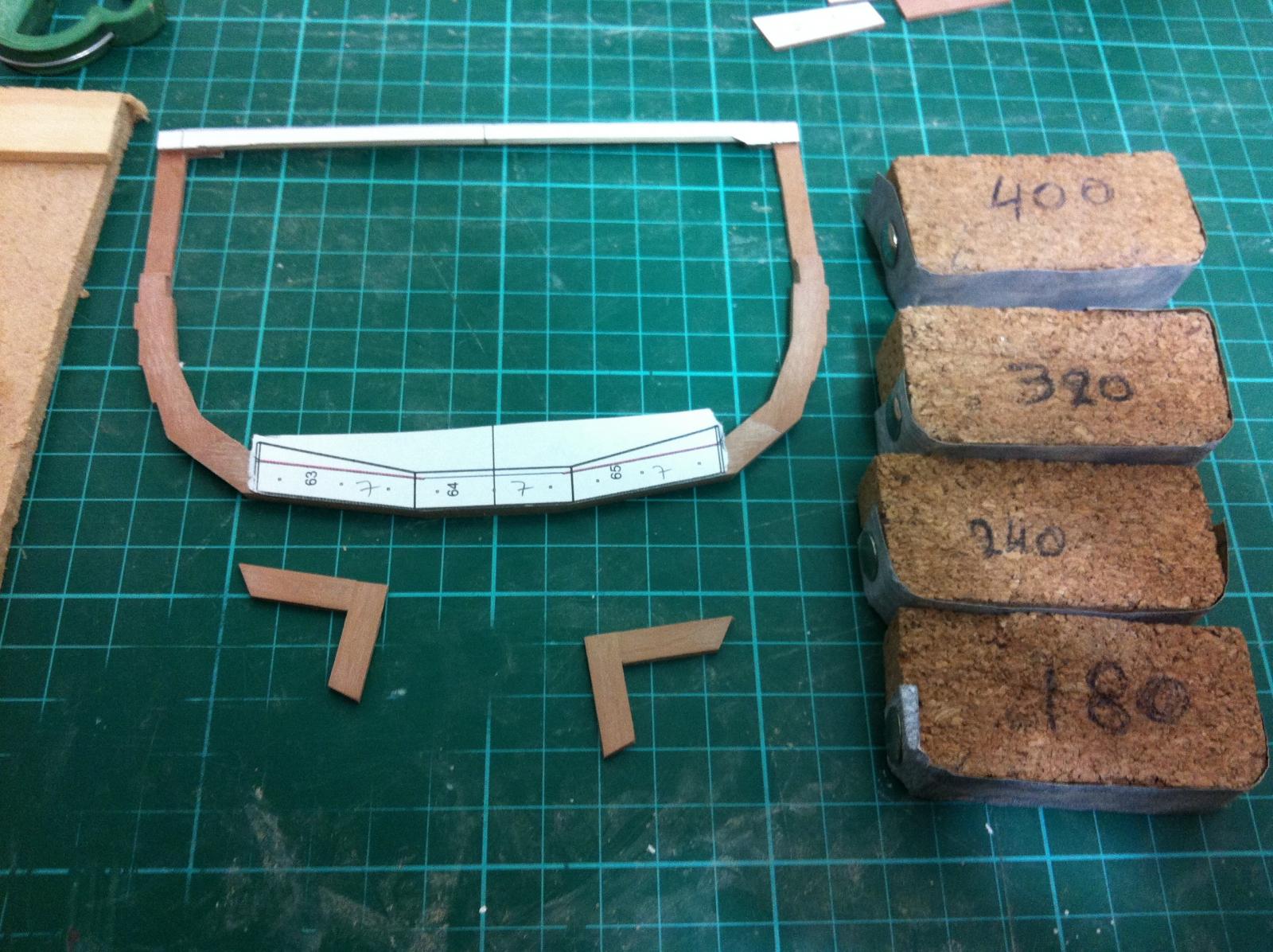
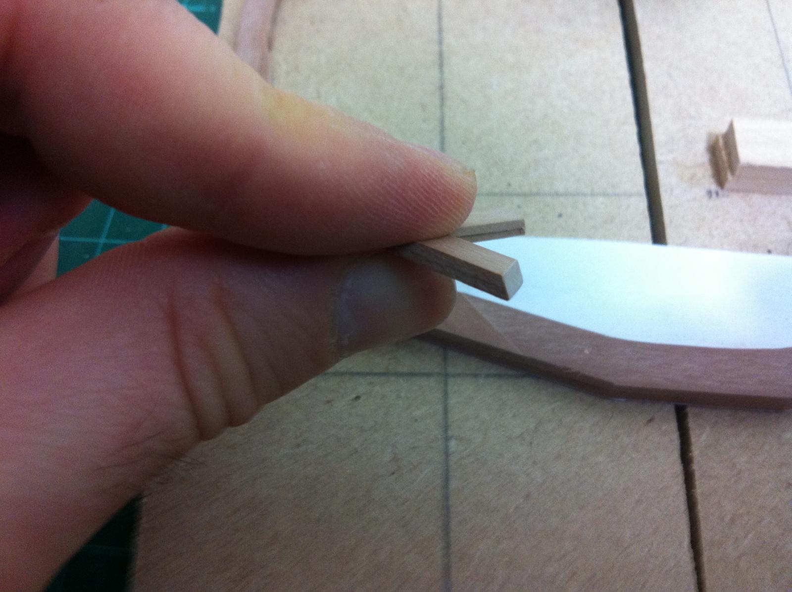
Next I started laminating the stem. The plans call for 16 mm wide strips and I could only get this dimension in walnut 1 mm thick. The overall thickness of the stem is 3 mm and I think that the resulting 2 layers of epoxy might not be enough to provide rigidity. I managed to find 0.5 mm maple sheet to cut strips for the laminate which will double the epoxy layers.
I will first laminate the first 2 mm, bevel these and then add the last 1 mm which will be shaped as the keel. I am hoping the bottom panels will then fit flush sitting nicely on the bevels.
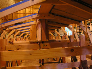
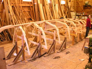
The american group did something similar
It will not work of course as it is far too optimistic a plan but I will give it my best shot. Besides, this is what I would do building the full scale boat.
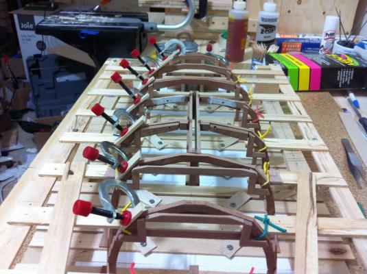
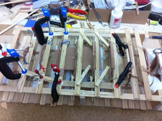
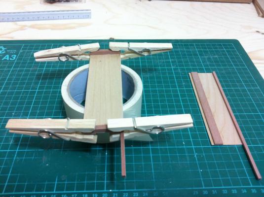
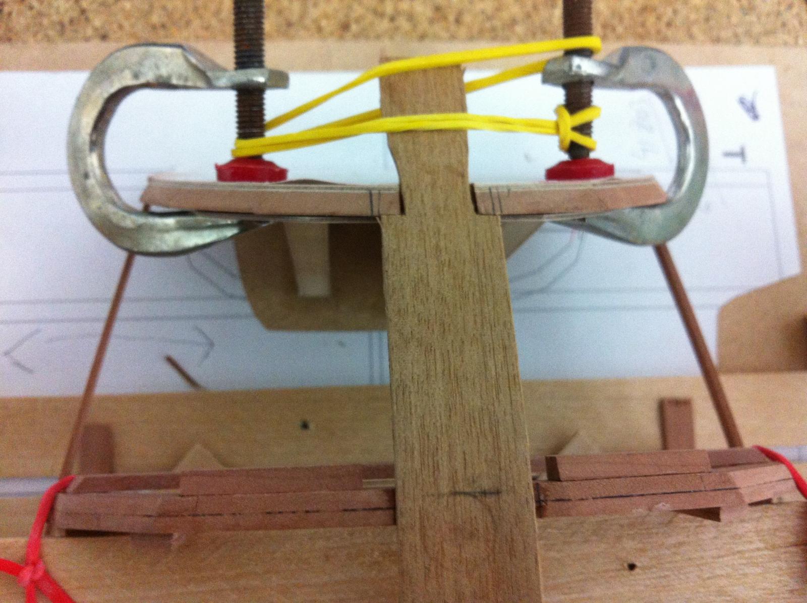
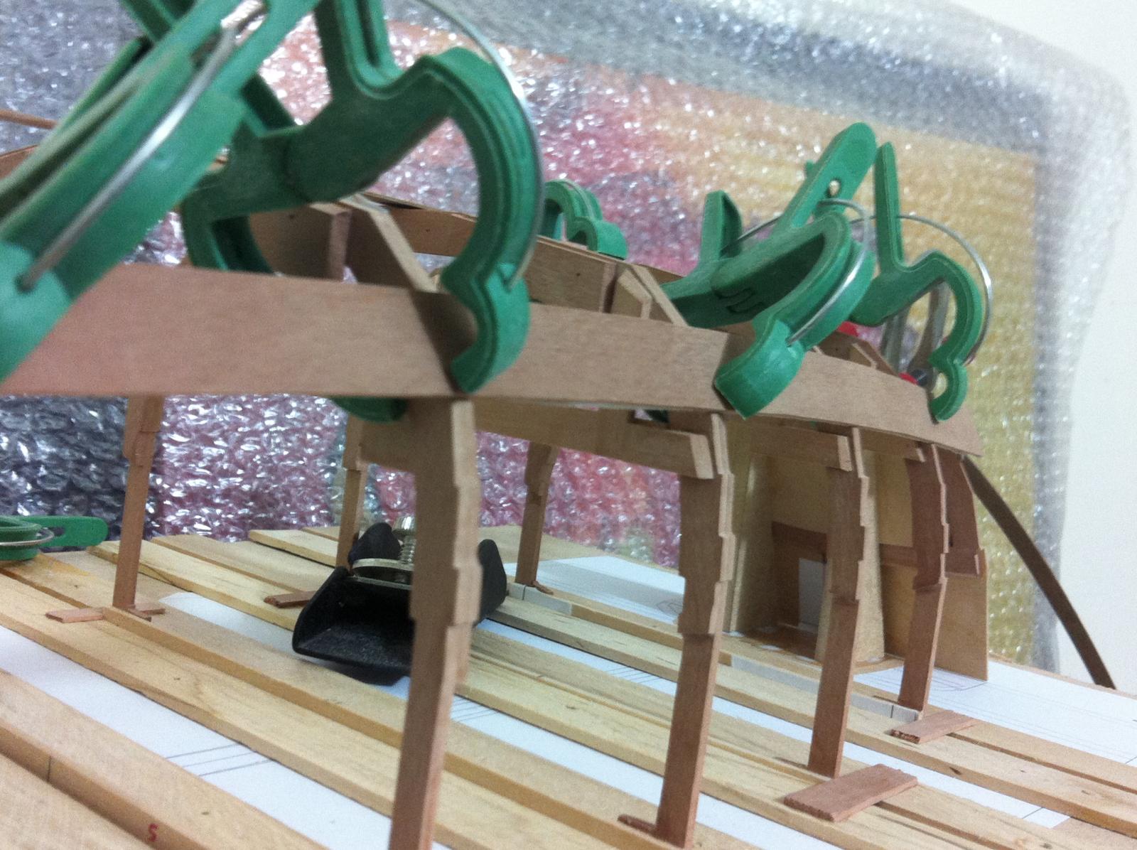
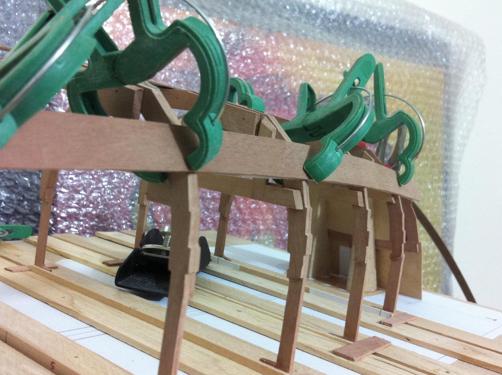
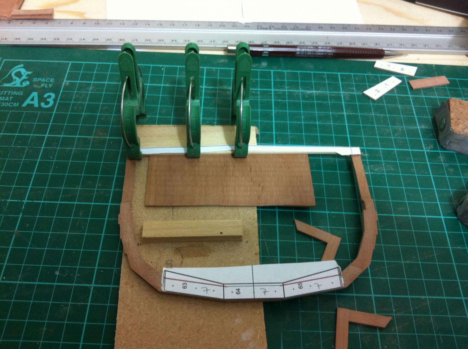
The first strip 1mm thick is epoxied into place. The transition from the last frame to the Transom does not look too faired but it is too late now.


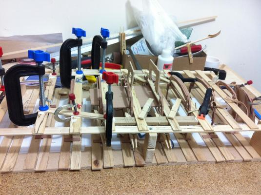
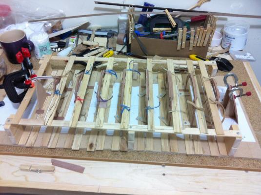
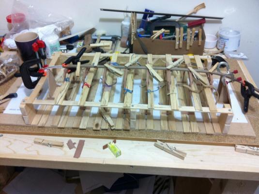
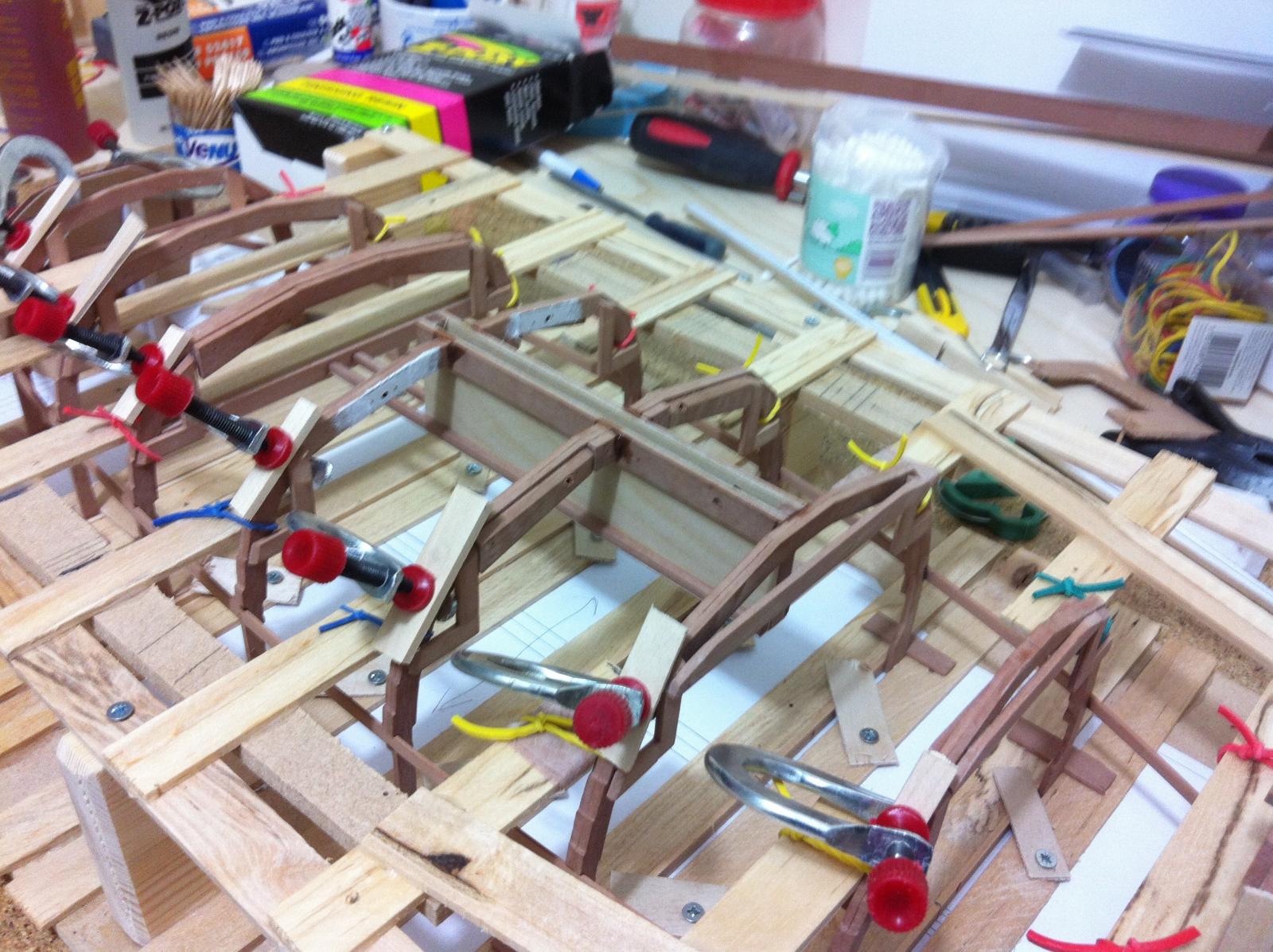
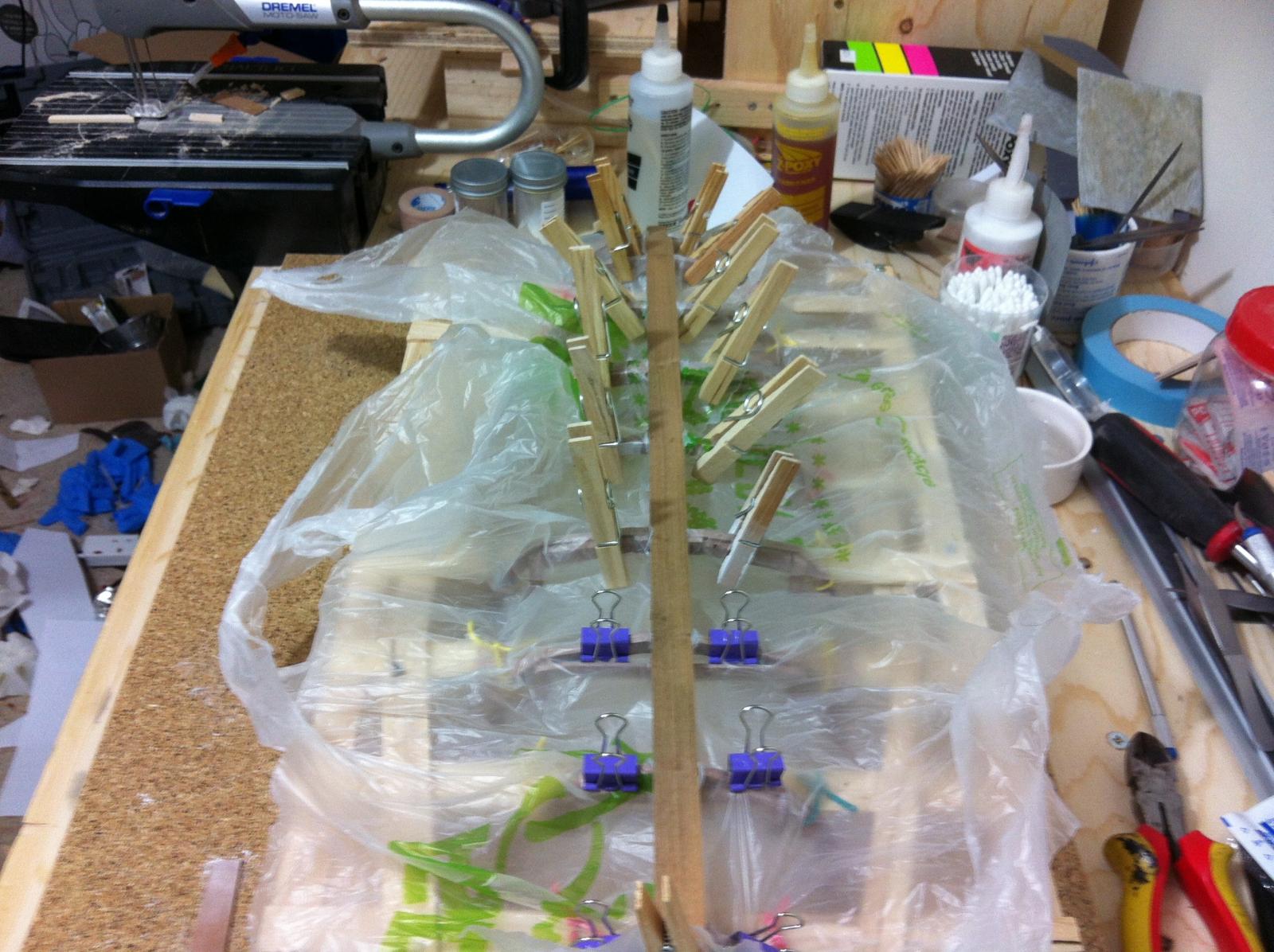
Preparing to laminate the rest of the layers

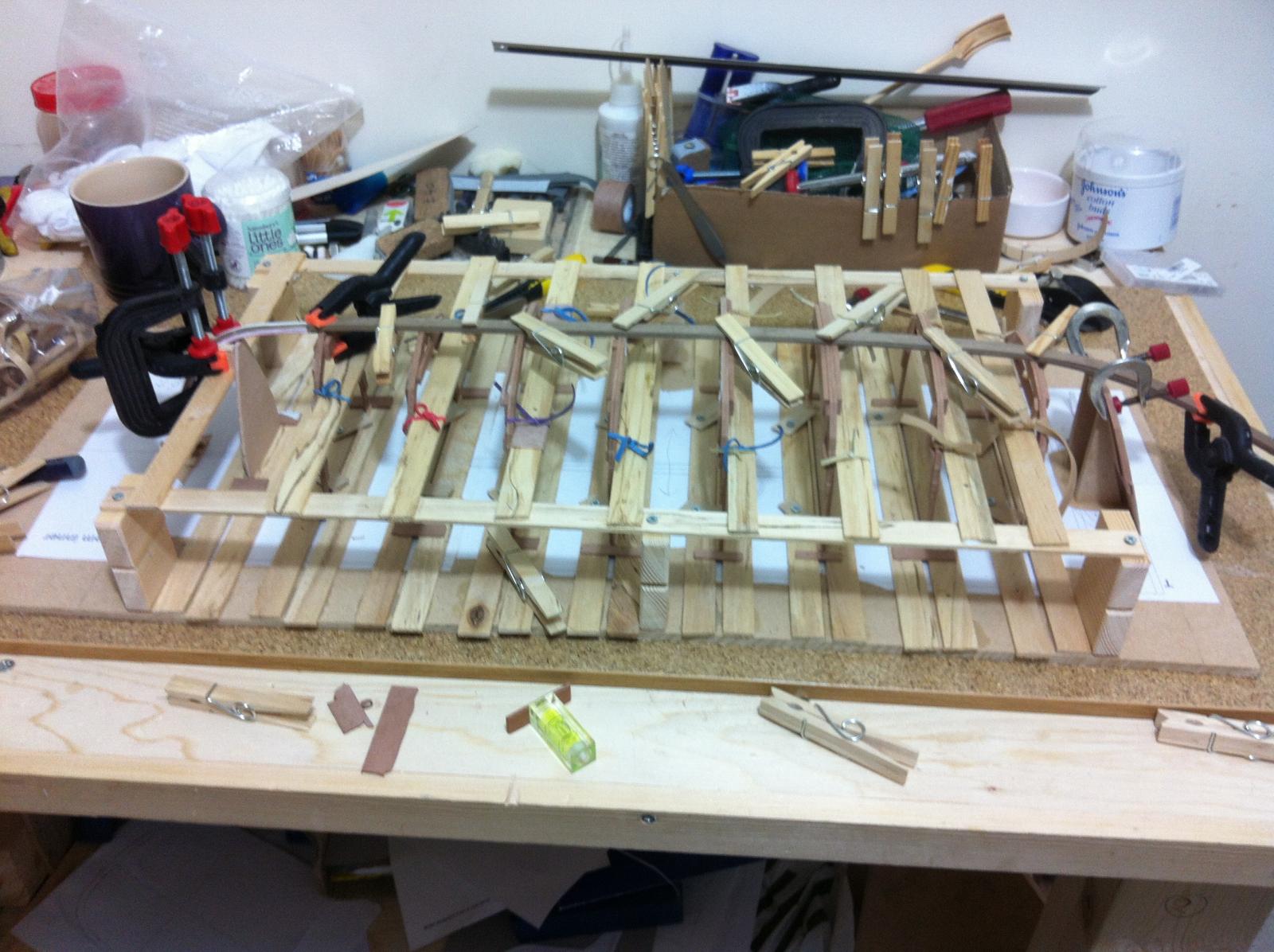
You can never have enough clamps
The hull should now be very rigid. I will probably add another strip to connect all frames (beyond the sheer line) to strengthen the structure even further and remove the cross beams of the jig. The stem will probably need some form of re-enforcement as well.
Things are getting very complex and difficult now. And with all the epoxied parts there is no going back!
-
Hi Greg, I think that designing the whole boat on CAD helped a lot as I understood the plans much better.
The Centerboard case is very sturdy and the fit already snag but your suggestion is good, packing the case will assist in gluing the mid portion of the case to the frame, although it could also slightly distort the unstable frame.
The outer clamps will be added, then the apron and then the bottom panels. At this stage the hull should be rigid enough and it might be even possible to rotate it to apply epoxy filleting and the transom knee. The US team used epoxy, although Tad designed it epoxy-free with just rivets. No harm in overbuilding though!
-
Thanks for the support Patrick, I never expected this simple boat to be so complicated and challenging. This is only my second boat and I have very little experience but I think that the curved keel and the centerboard add a huge amount of complexity. This boat needs to be held up in the air to be built!
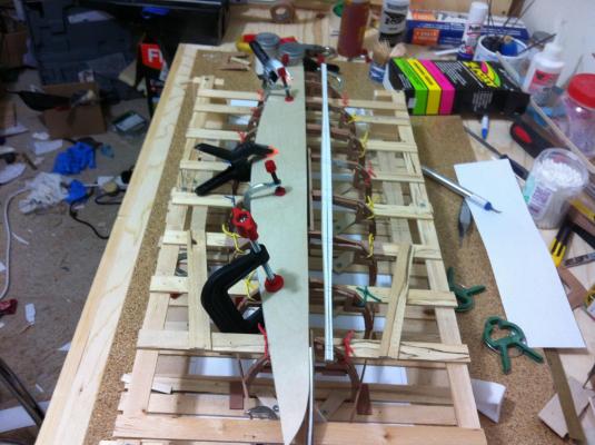
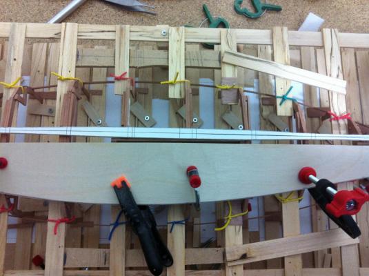
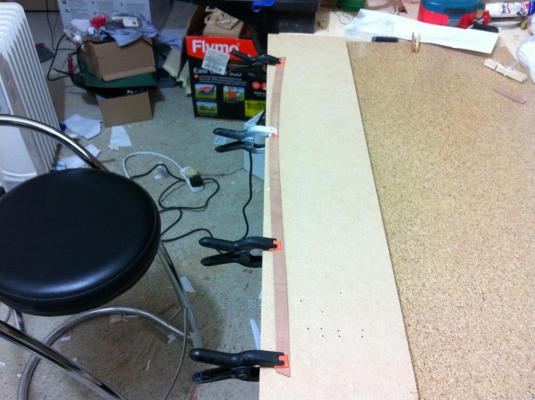
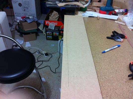
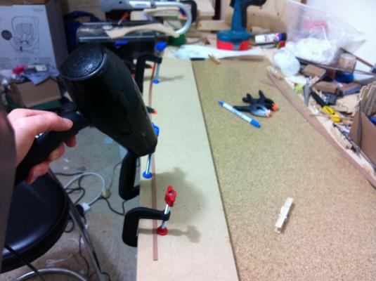
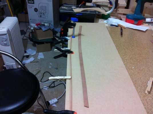
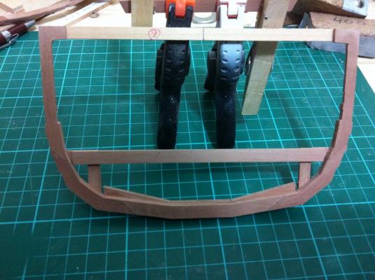
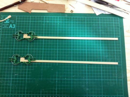
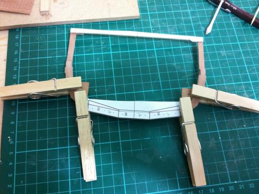
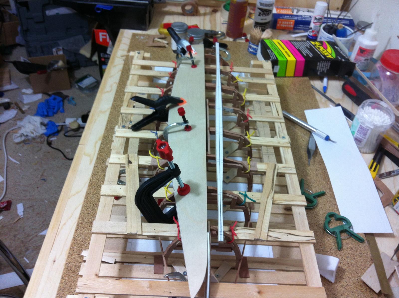
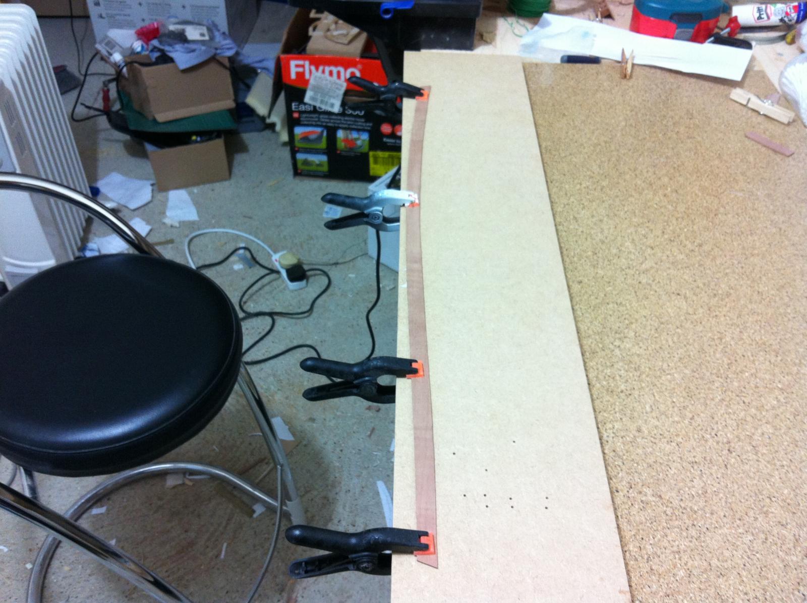
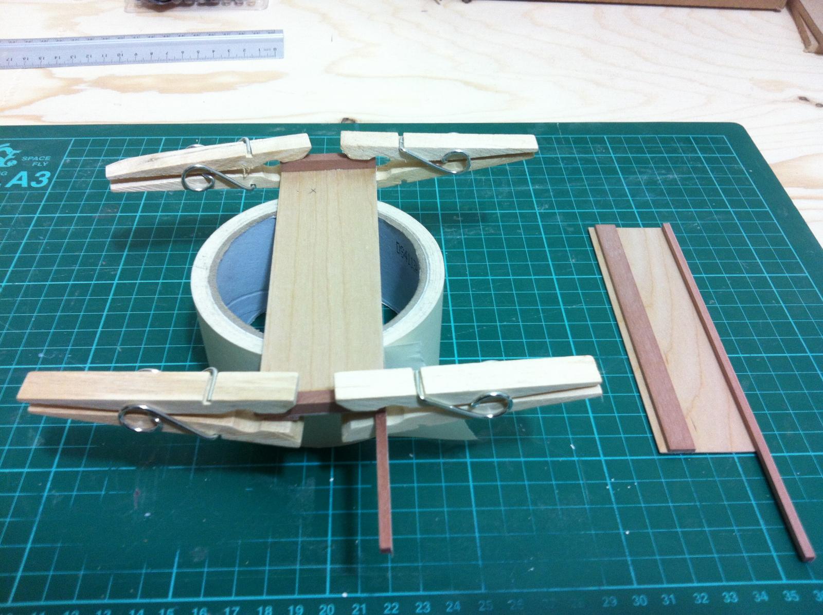
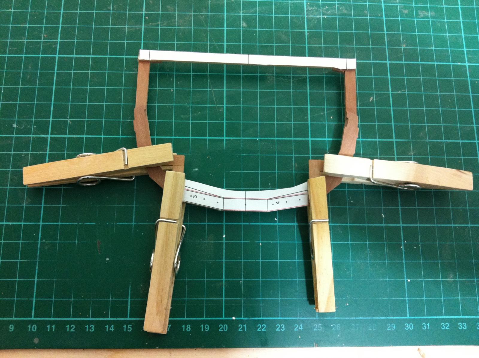
I was reading various posts on the forum yesterday and I came across I think Chuck suggesting to pre-bent the planks to avoid lifting. I decided to do the same with the outer sheer clamps.
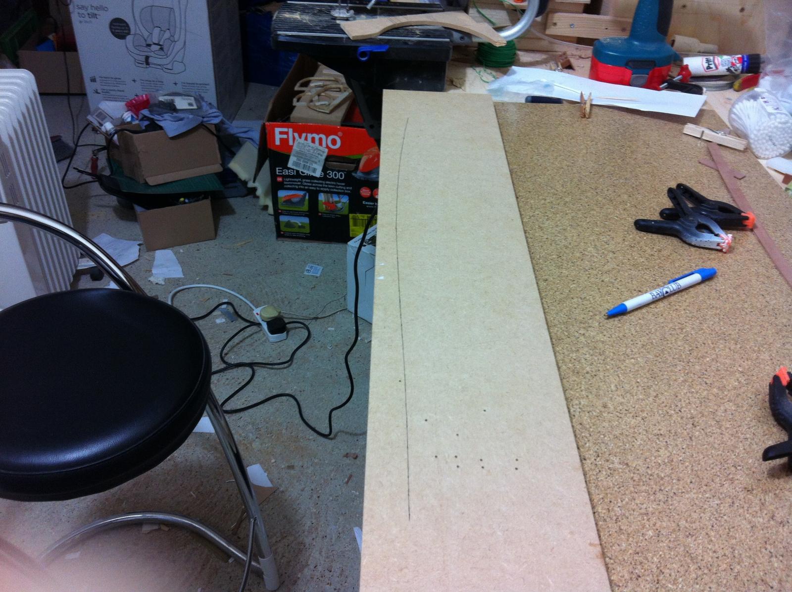
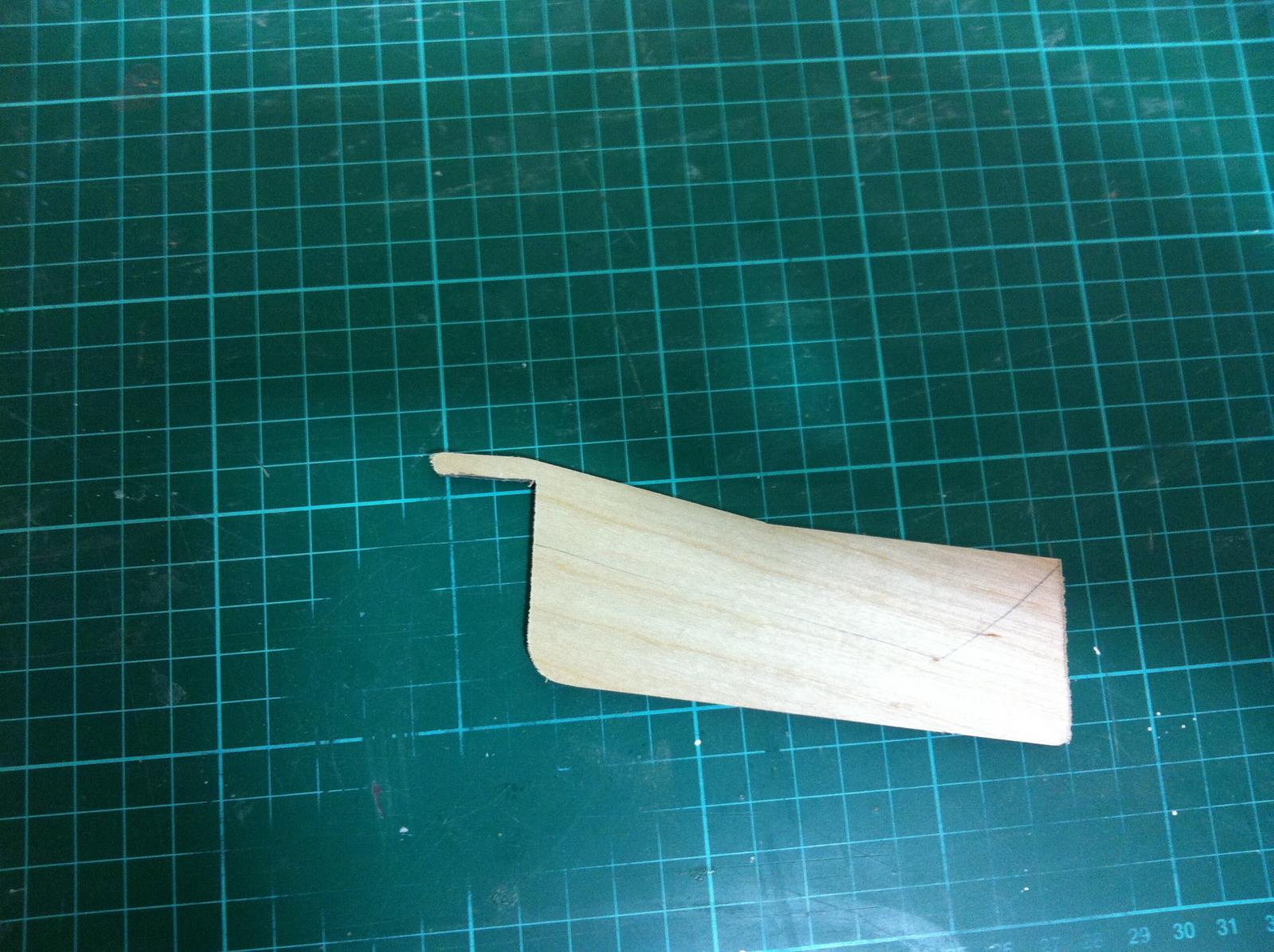
The next photo shows the upper most plank, I marked the sheer pattern and used it to secure the wet outer clamps and then used a hairdryer to dry them. I included some overcorrection to compensate for spring-back. I have not test fitted them yet but they should be fine.
At this time I had to face the fact that the time for hard decisions and action has come. The keel needs to be laminated but if I do this first it will be impossible to install the Centerboard case. Viseversa, Installing the Centerboard case would be very difficult as the boat is being built upside down and the frames No 4 and 5 would need to be cut which means they would become unstable and loose alignment. This is a puzzle but it is clear the only way out is to do something irreversible!
The american team installed first the centerboard case. Their jig is sadly much simpler!
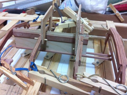
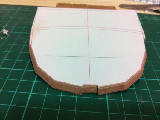
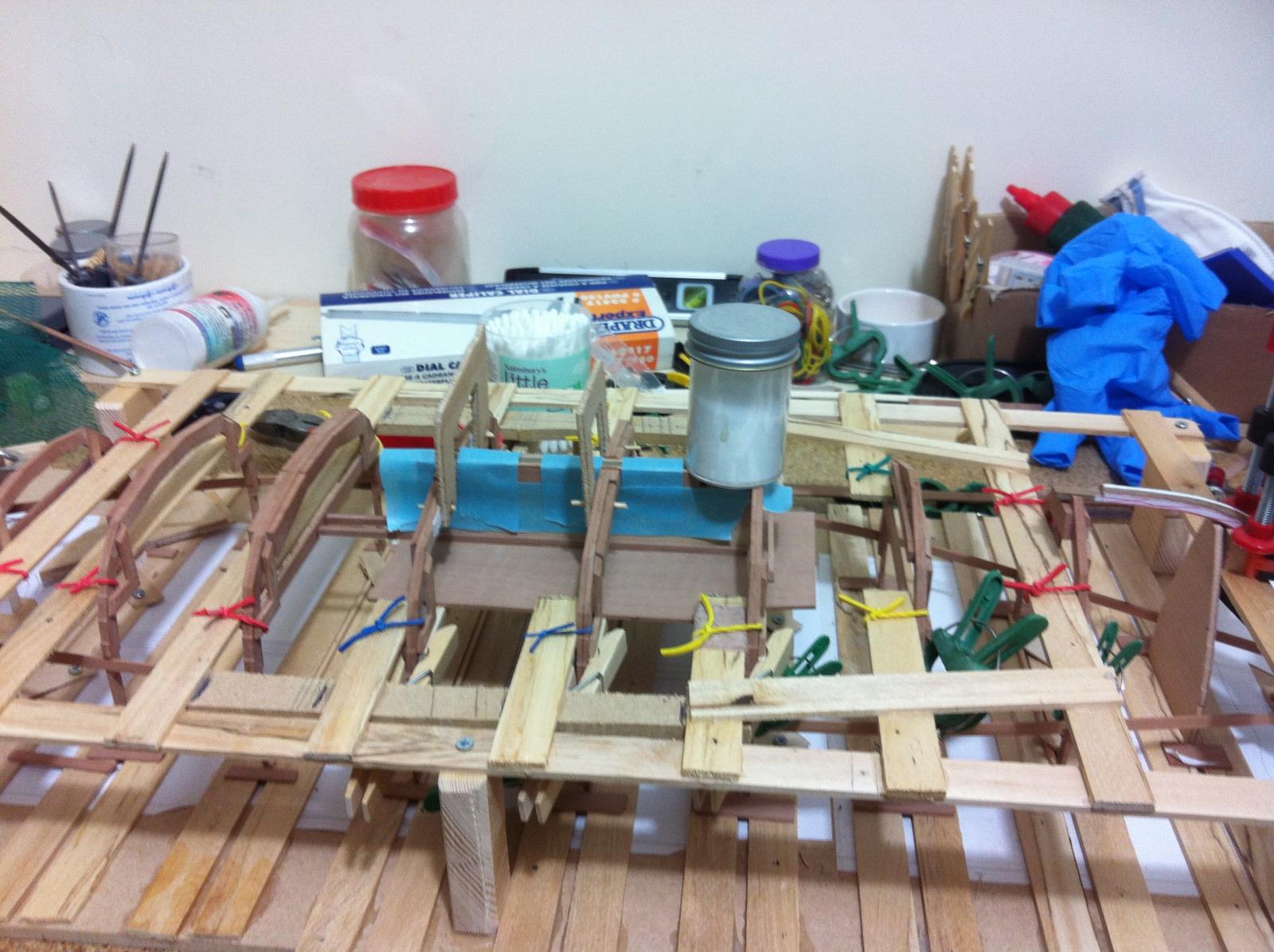
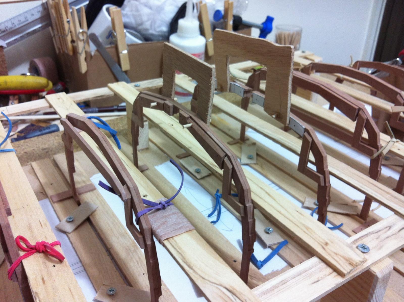
So the decision was made: cut the frames. I used 3mm liteply to try and stiffen up the cut frames, this did not work very well but still kept the frames aligned. I did not cut the other frame all the way. According to my plans one of the frames should have a small step.


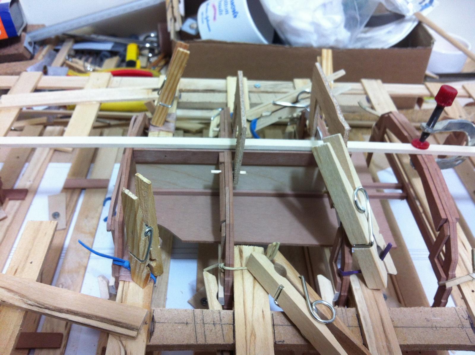
To install the centerboard some of the transverse beams had to be cut The jig had to be further reinforced so I glued scrap pieces of MDF and wood.
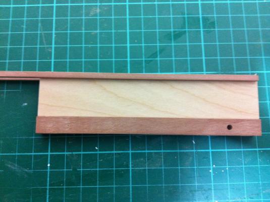
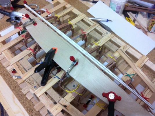
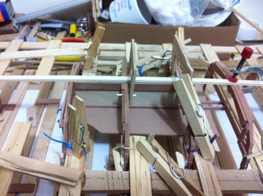
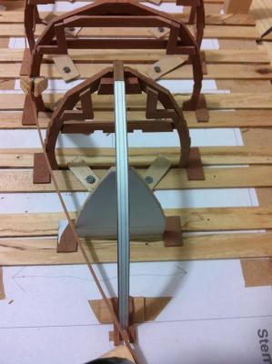
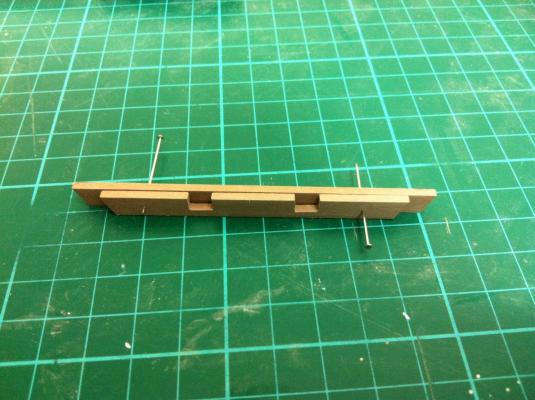
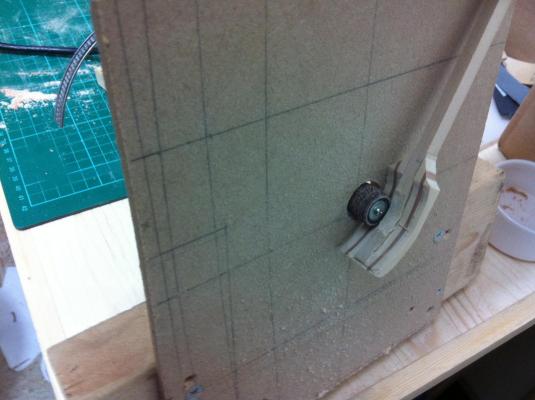
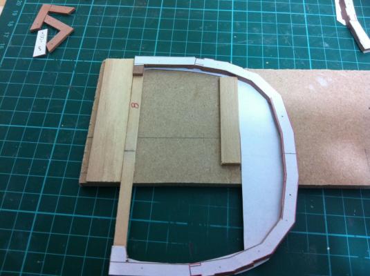
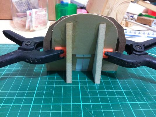
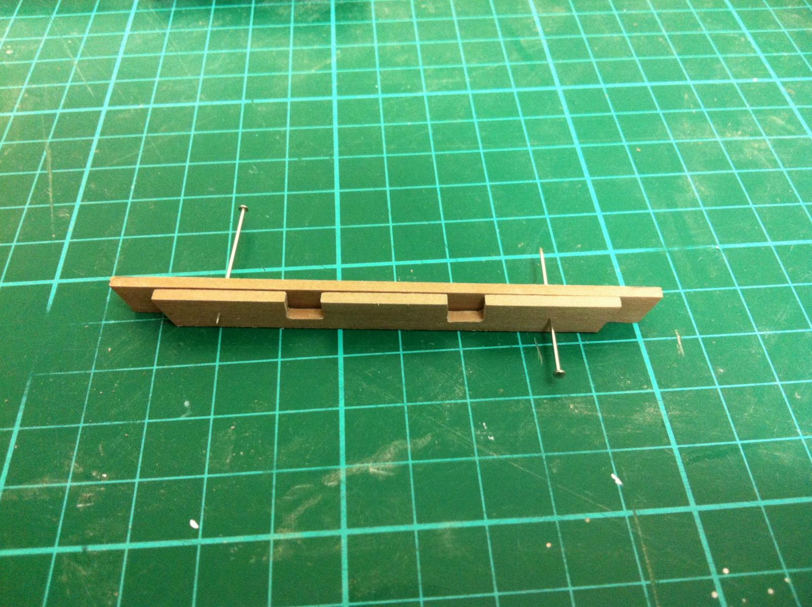
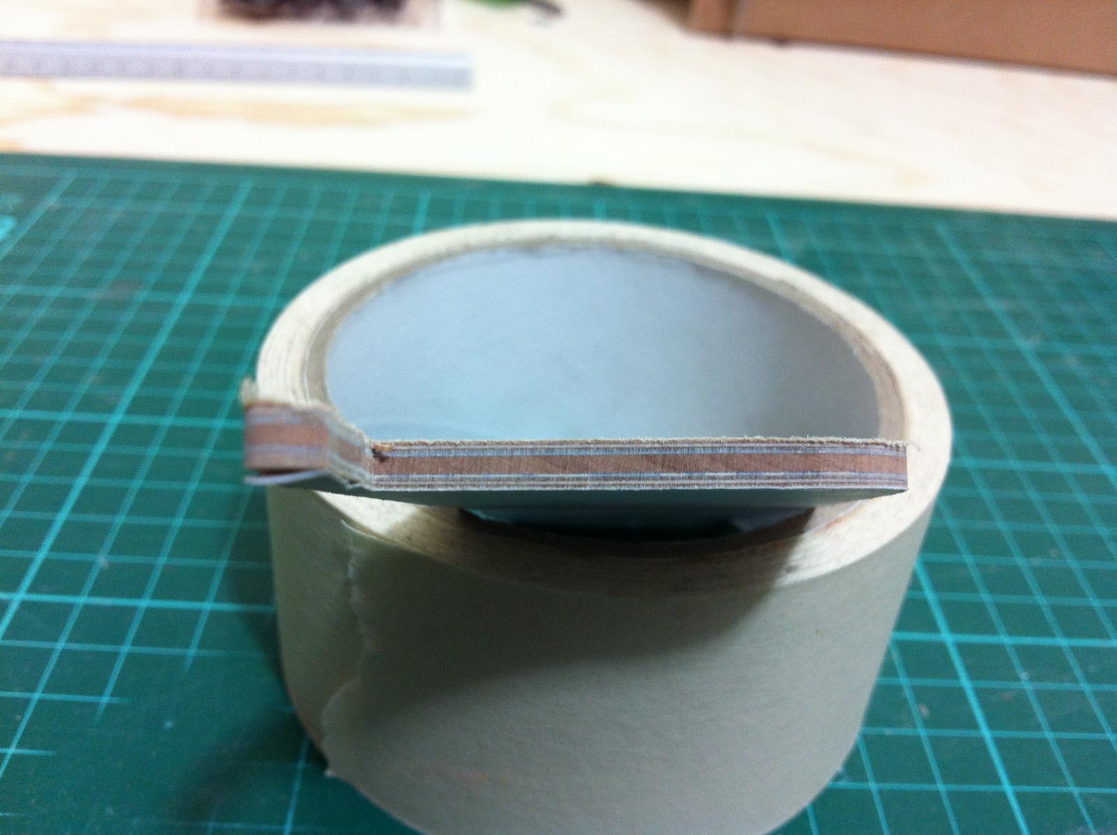
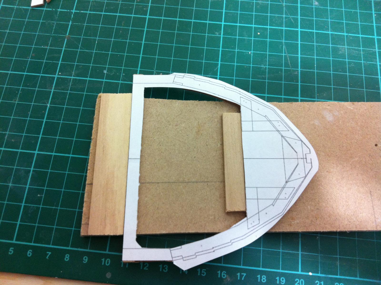
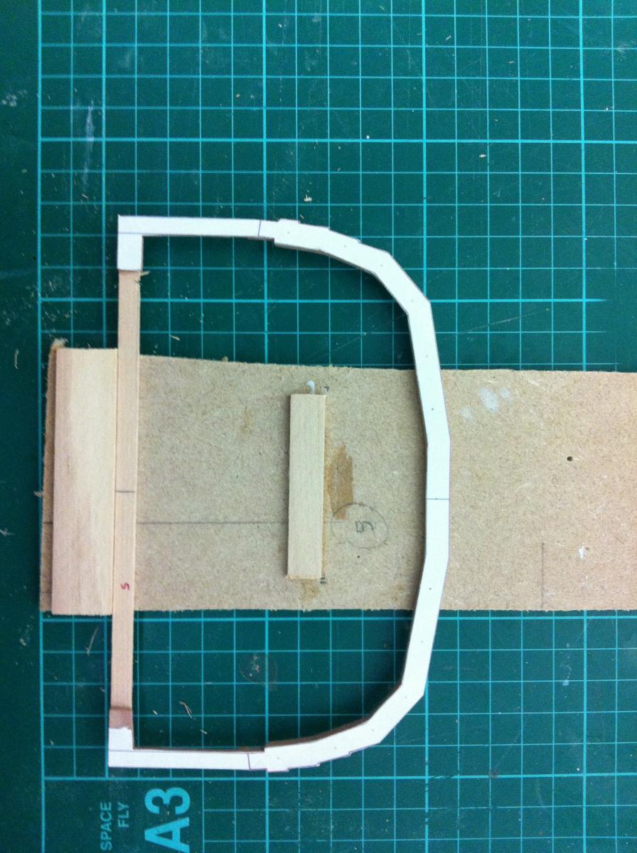
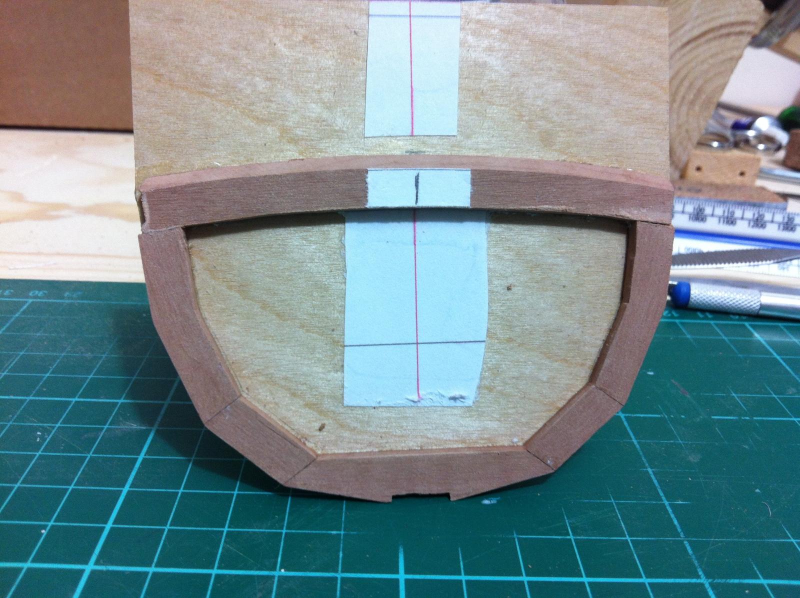
The next photo shows a floor suspended at the level where the top of the CB case should be
The beams where cut away. I actually cut by mistake the beam at station 2 but this did not matter. The jig is still super stiff
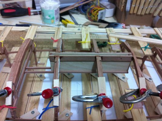
I test fitted the CB case and it is clear the frames need to be cut all the way as it still sits very high
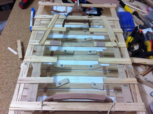
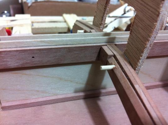
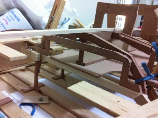
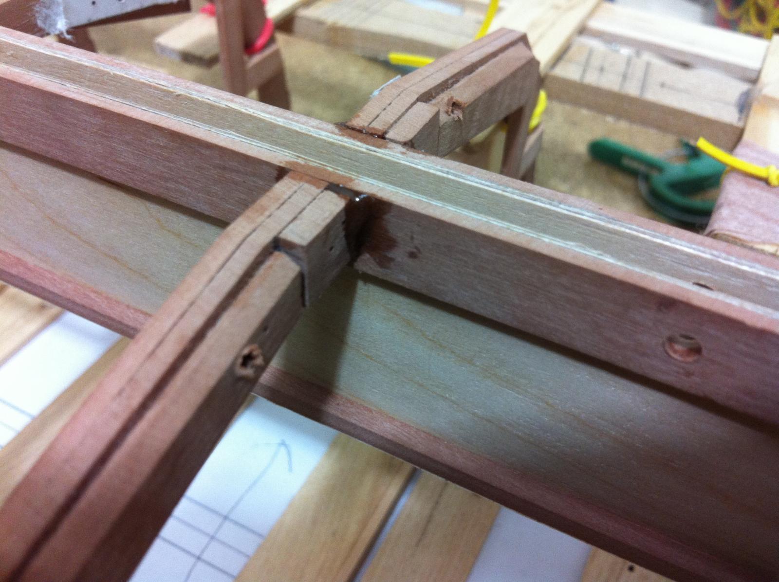
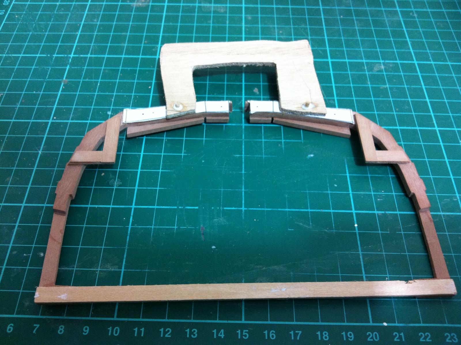
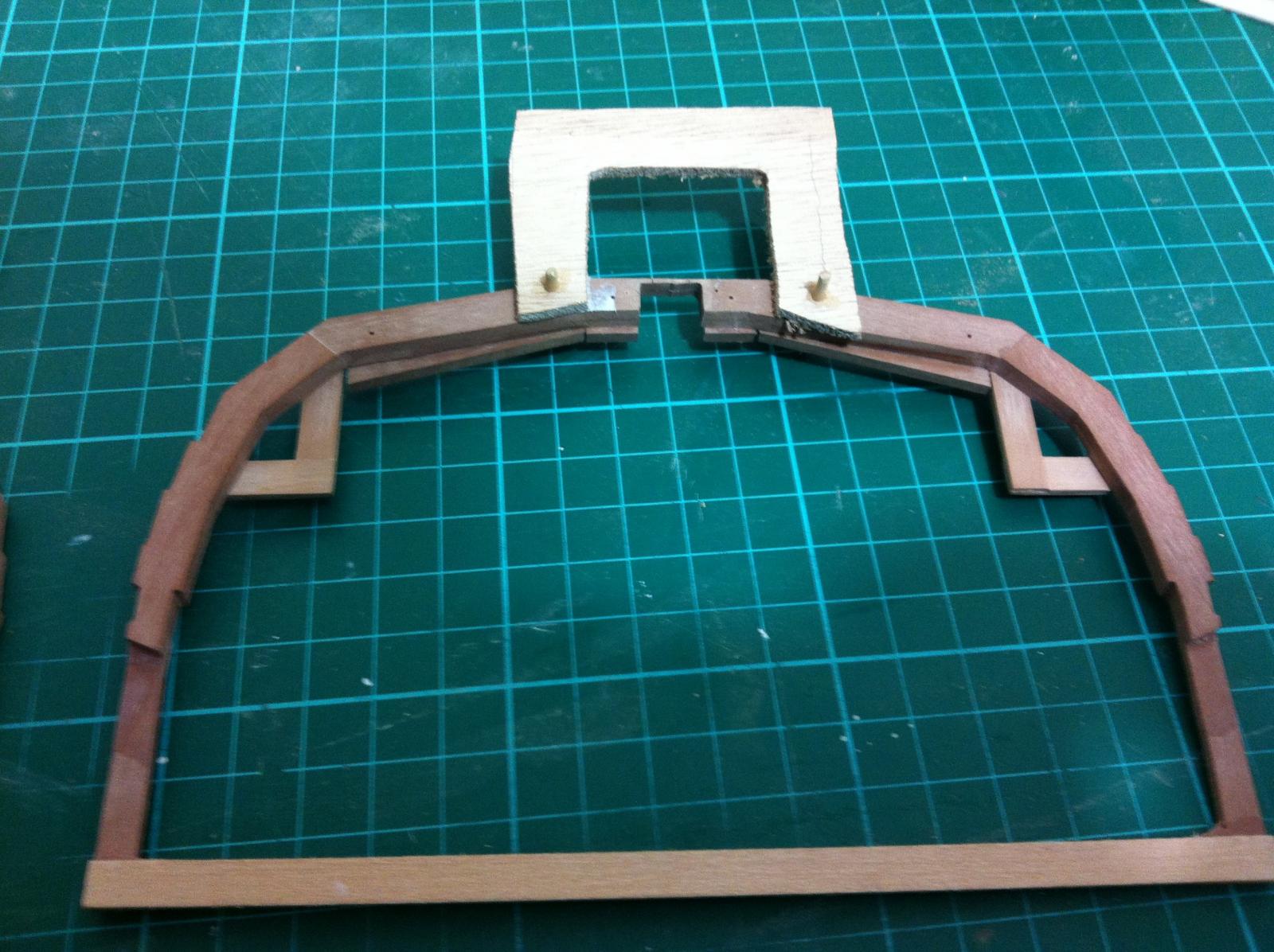
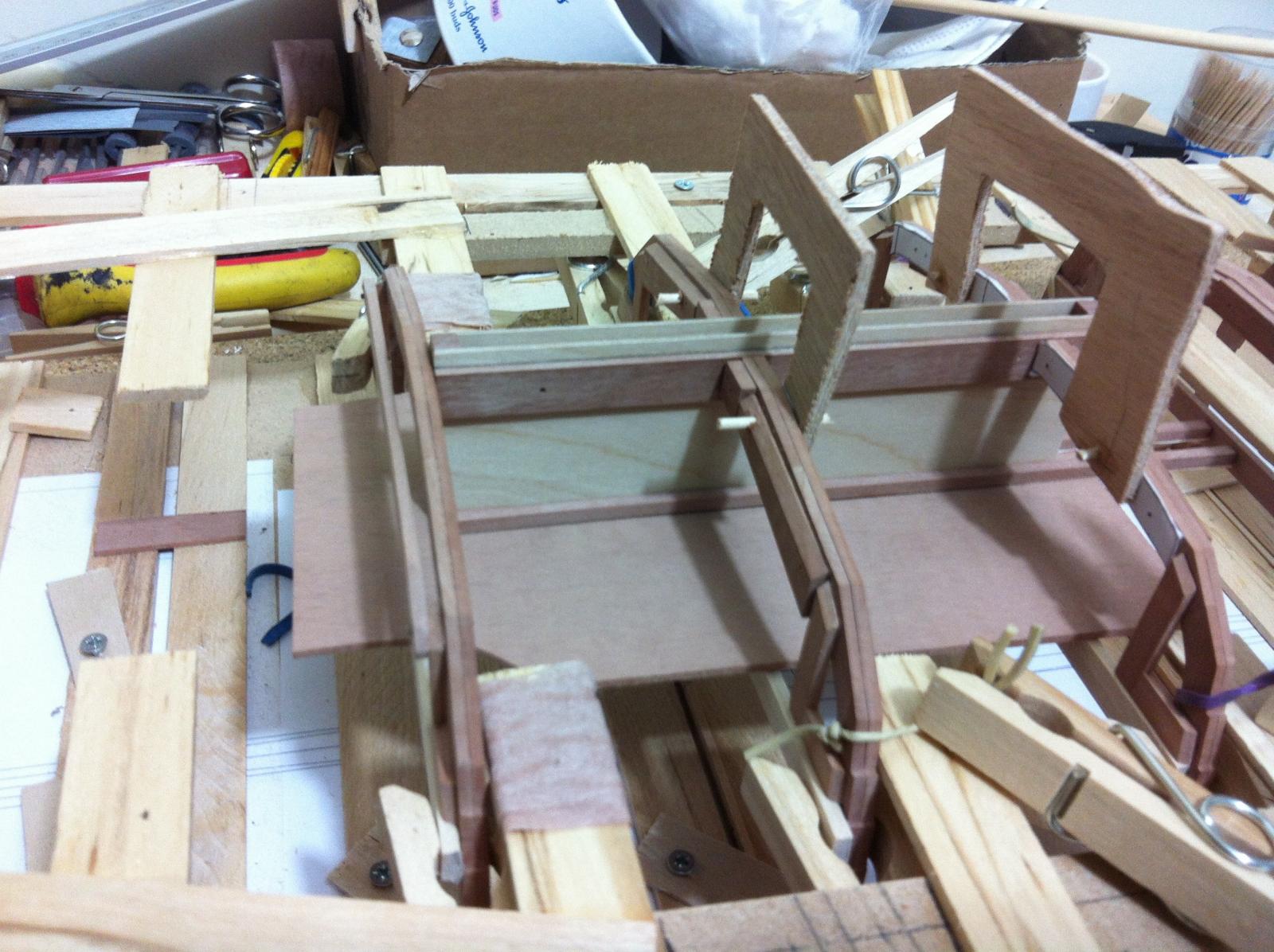
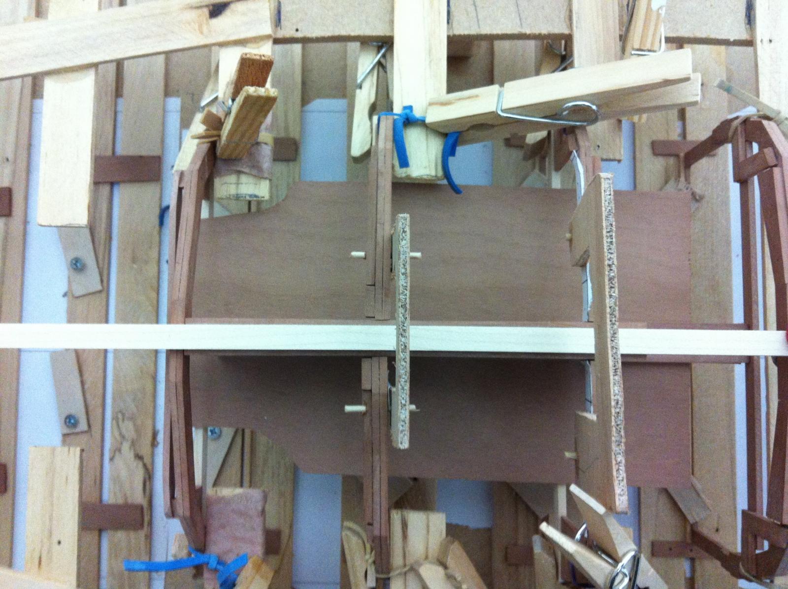
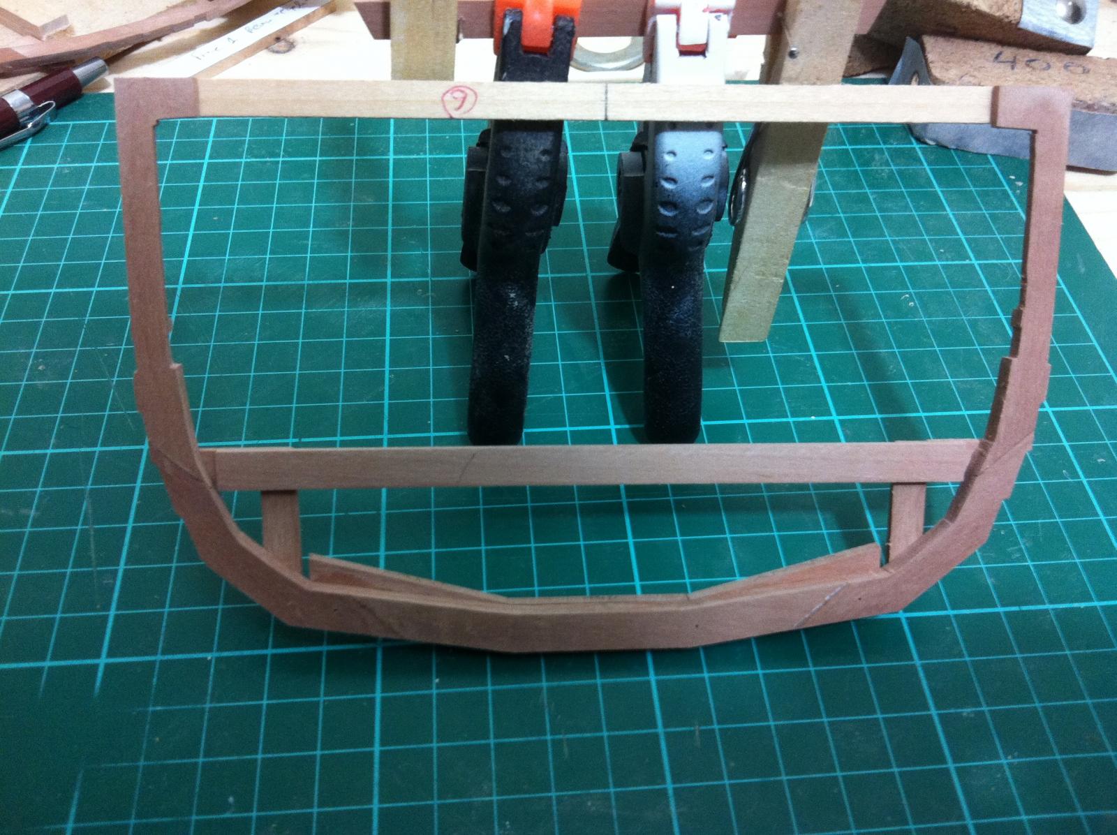
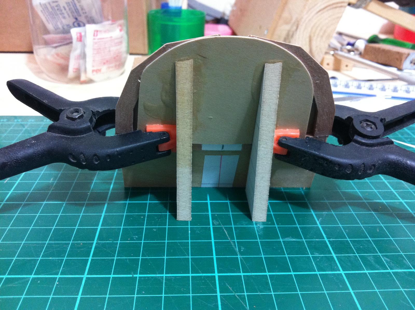
After some careful sanding everything somehow fell into place. The CB case rests on frame No 3, the reenforcing planks are square with the frames and the 2 small planks that run either way of the upper margin of the CB case and extend aft to meat the support of the thwart actually do so.
The centerboard case according to Tads plans extends a little to the Apron for added stiffness. I think this is immensely difficult to achieve in this scale.

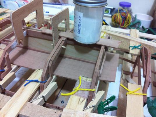
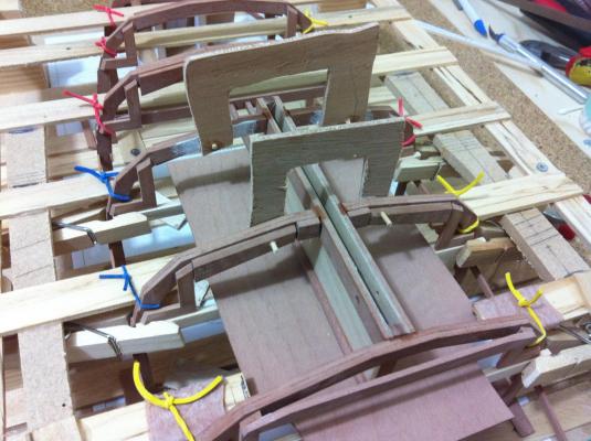
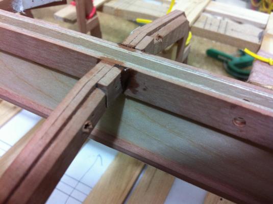
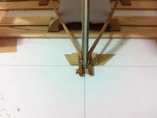
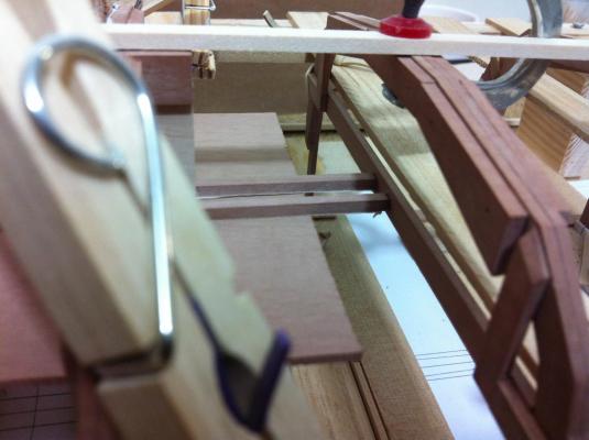
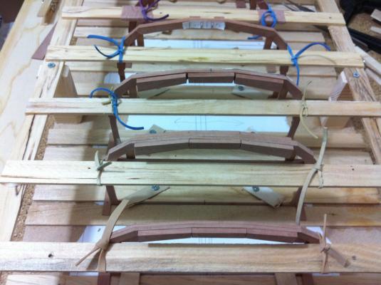
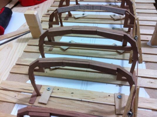
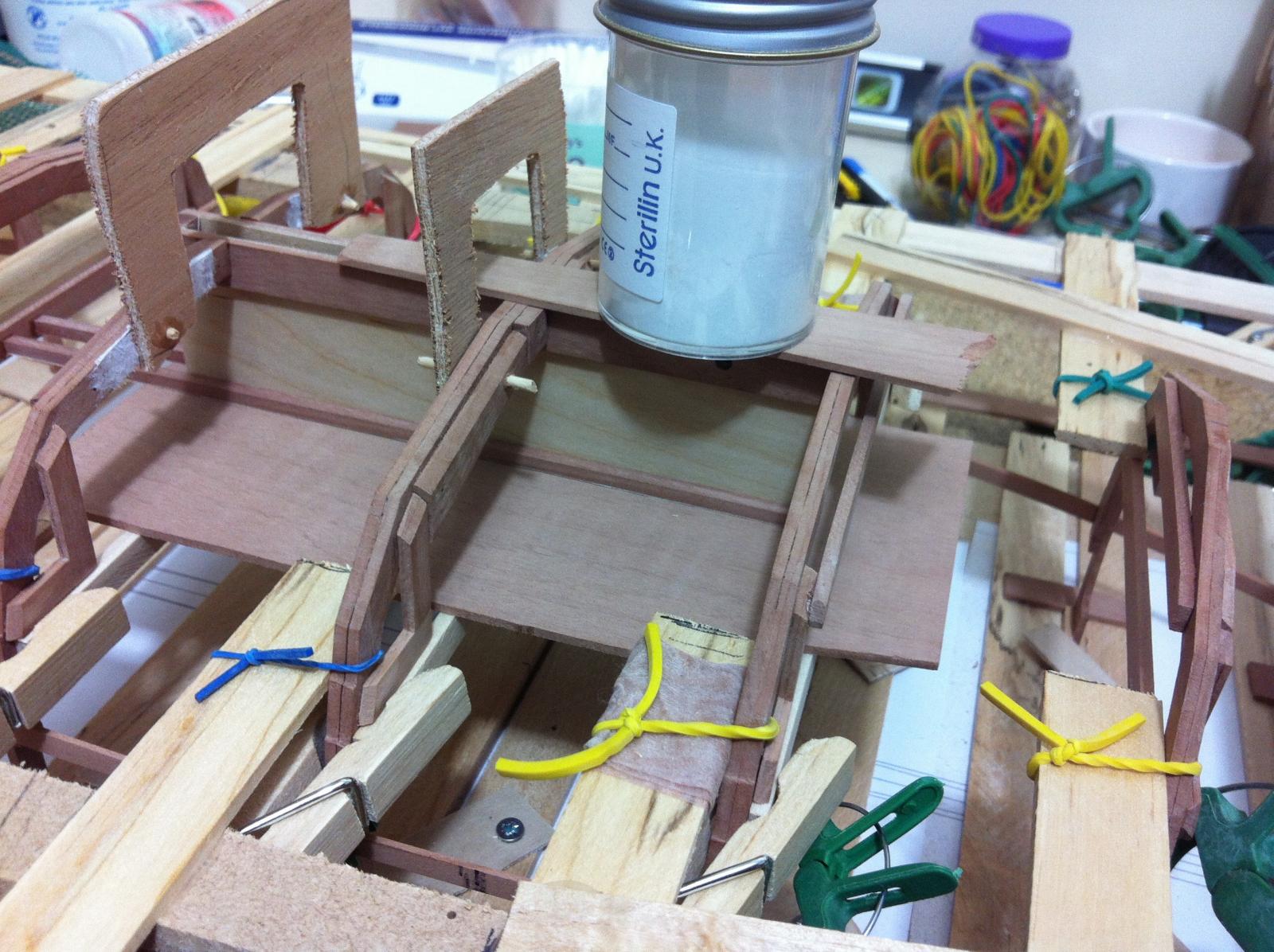
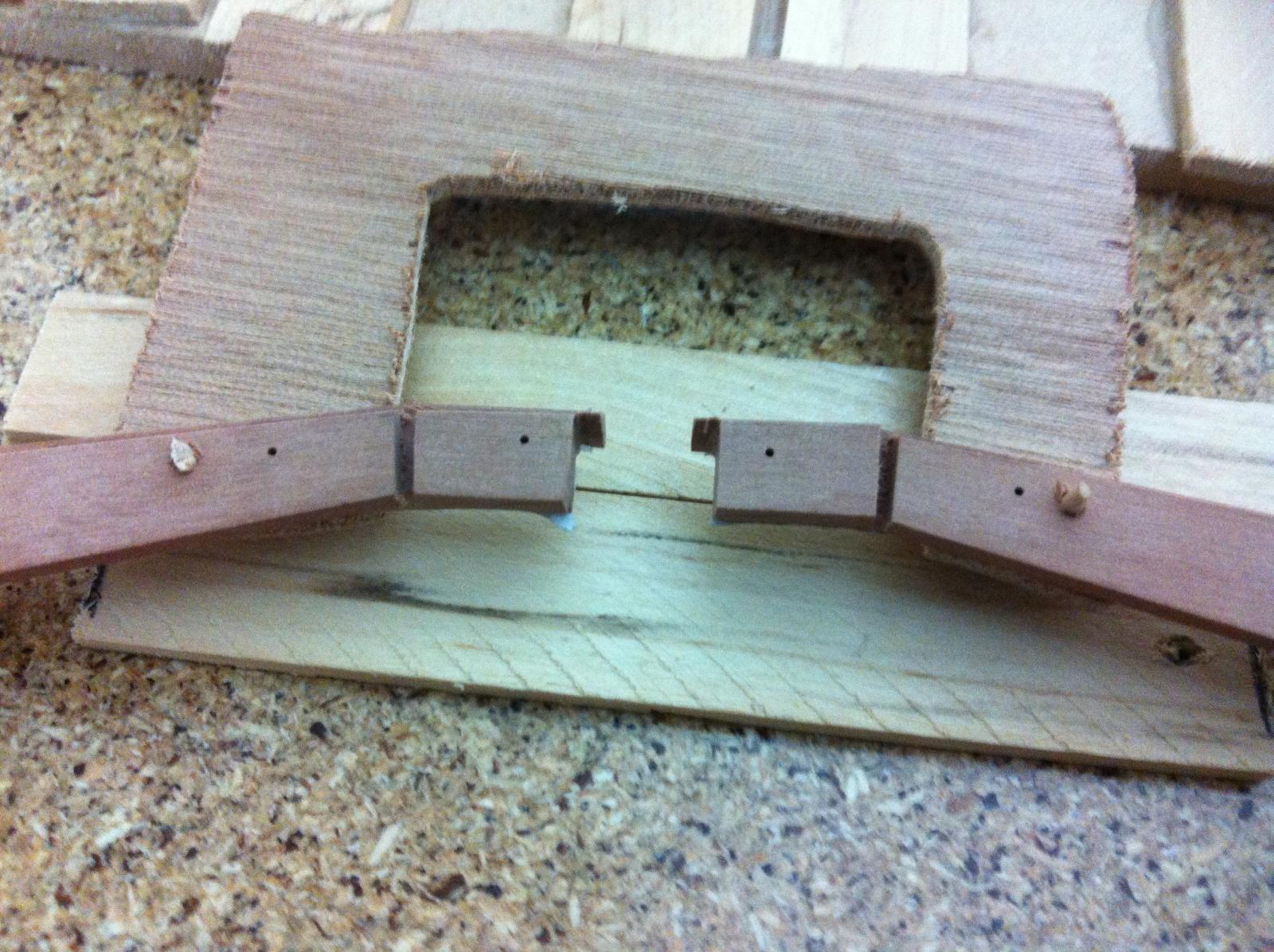
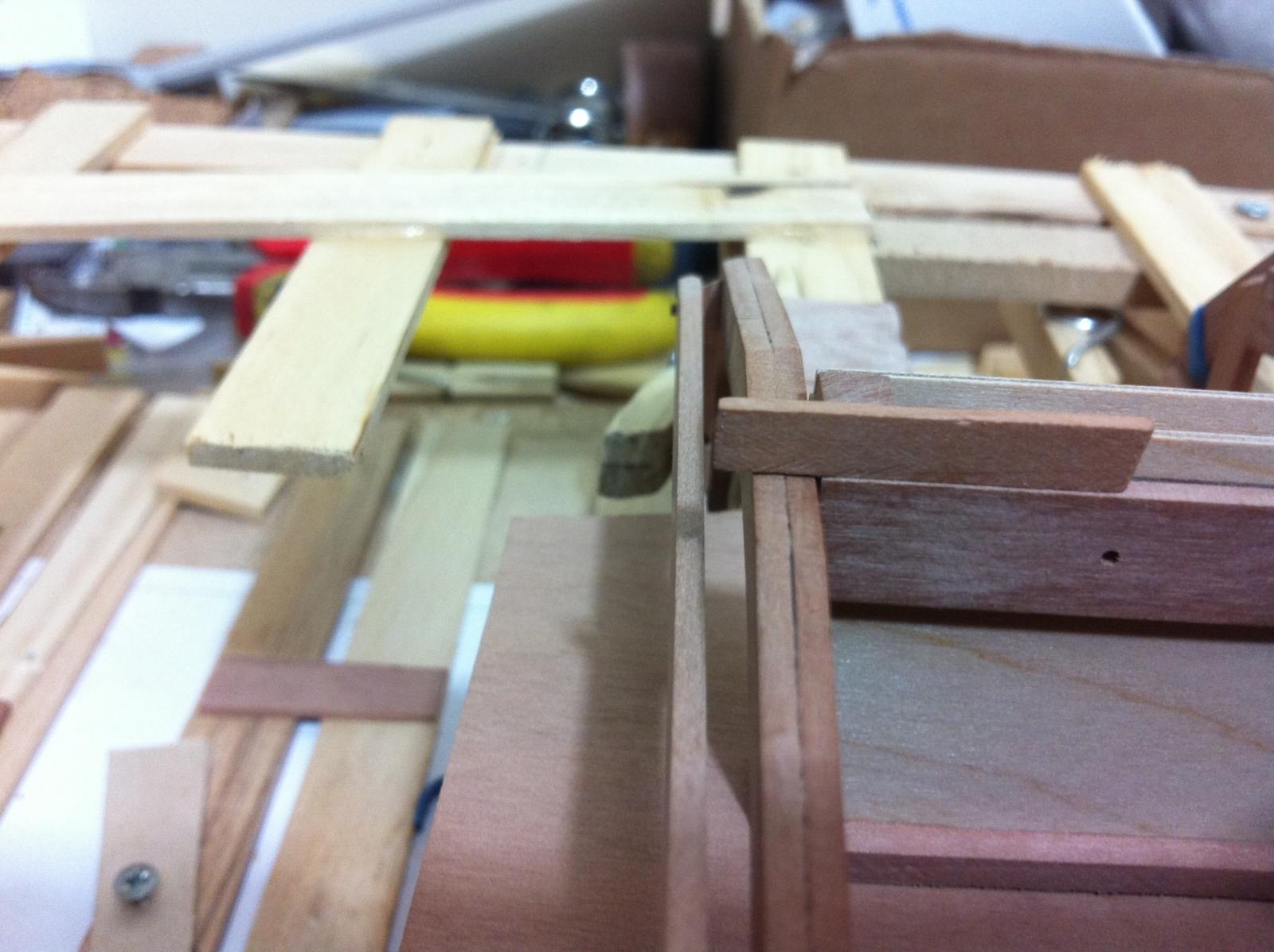
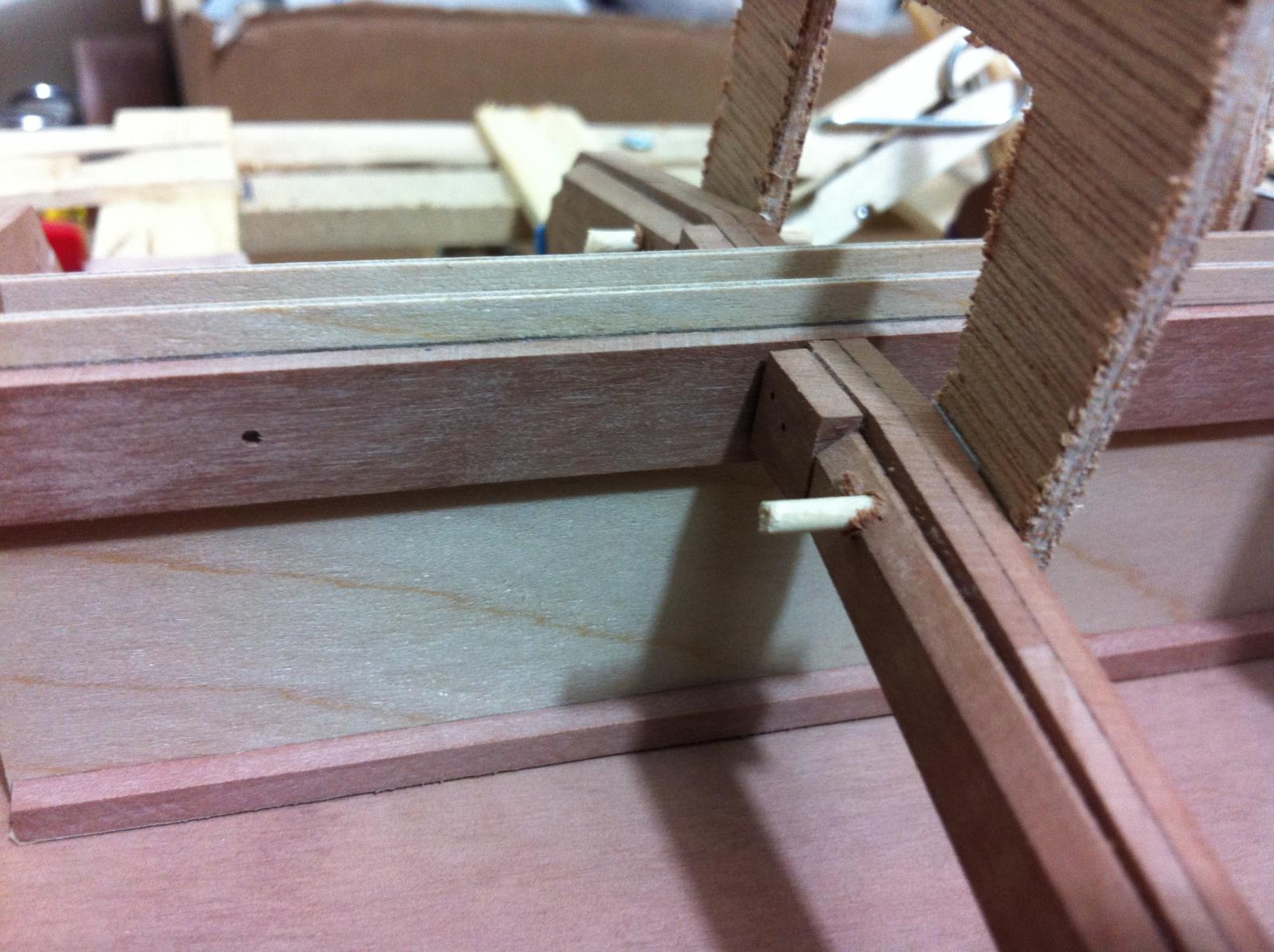
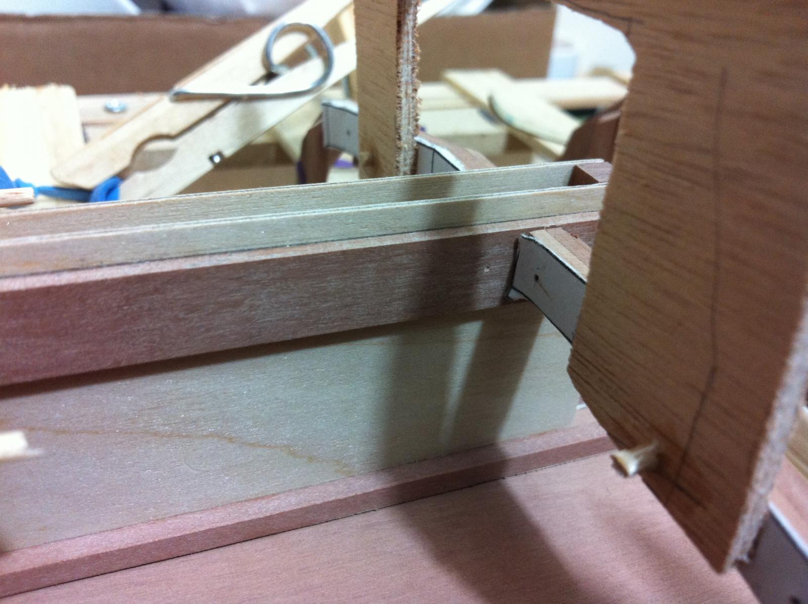
The next photos show the junction of the CB case with frames 3, 4 and 5


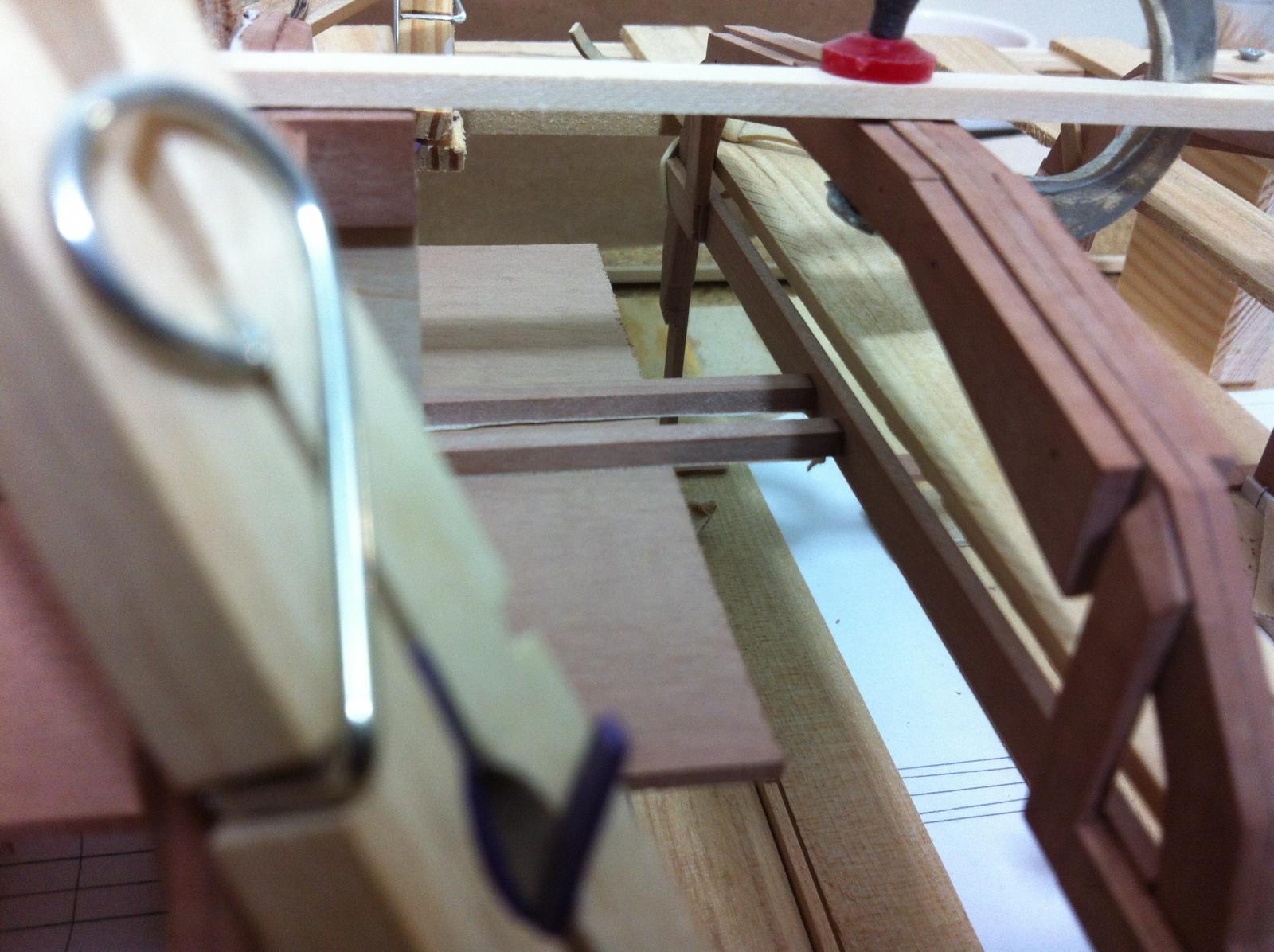
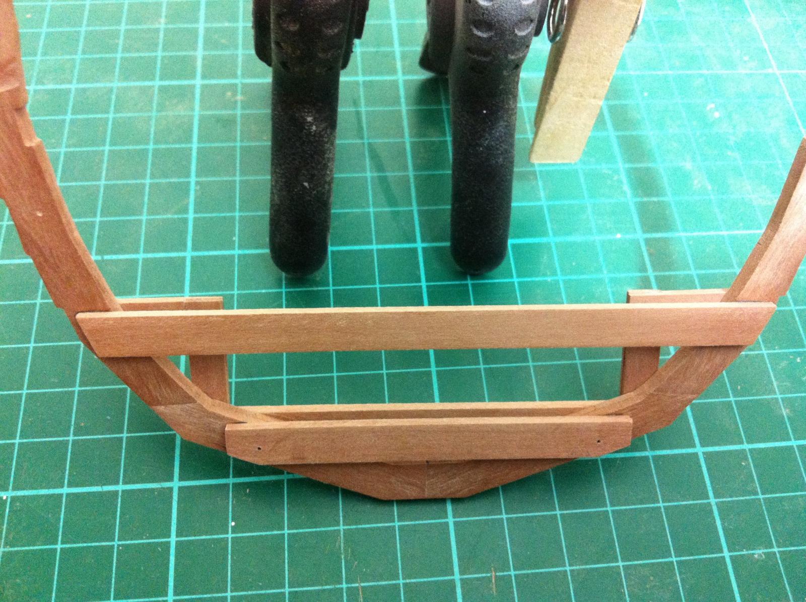
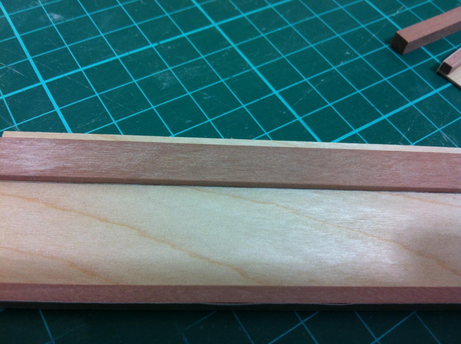
I carefully trimmed the excess case off. Everything seem to sit flush, I fitted a maple strip to make it easier to see the fit. All seem reasonably centered. The last photo shows the two planks reaching the thwart support.

Next task to carefully glue with epoxy, maybe thickened with pearwood saw dust. I will need to make sure no glue appears above the floor line and first I need to open the hole for the centerboard pivot.
- druxey, mtaylor, captainbob and 6 others
-
 9
9
-
Work is progressing slowly, due to other commitments and also because I am unsure of how to proceed further, these are uncharted waters. I think that these should be the next steps:
1. Secure the frames to the jig and laminate the apron
2. Remove the frames, cut frames 4 and 5 to allow fitting of the centerboard case , deepen the notches for the outer clamps in all frames
3. Re-mount frames on the jig, install the outer clamps, install the centerboard case (how?)
4. Install the garboard plywood sheet, this will require bevelling of the apron (how?)
Easier said than done!
First thing's first so here it goes.
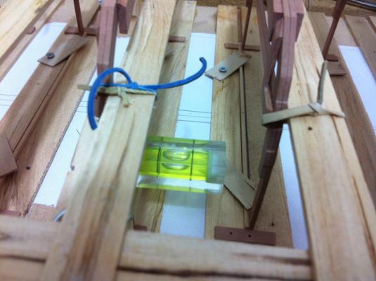
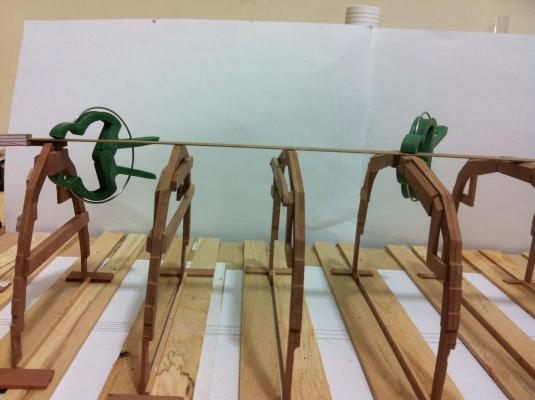
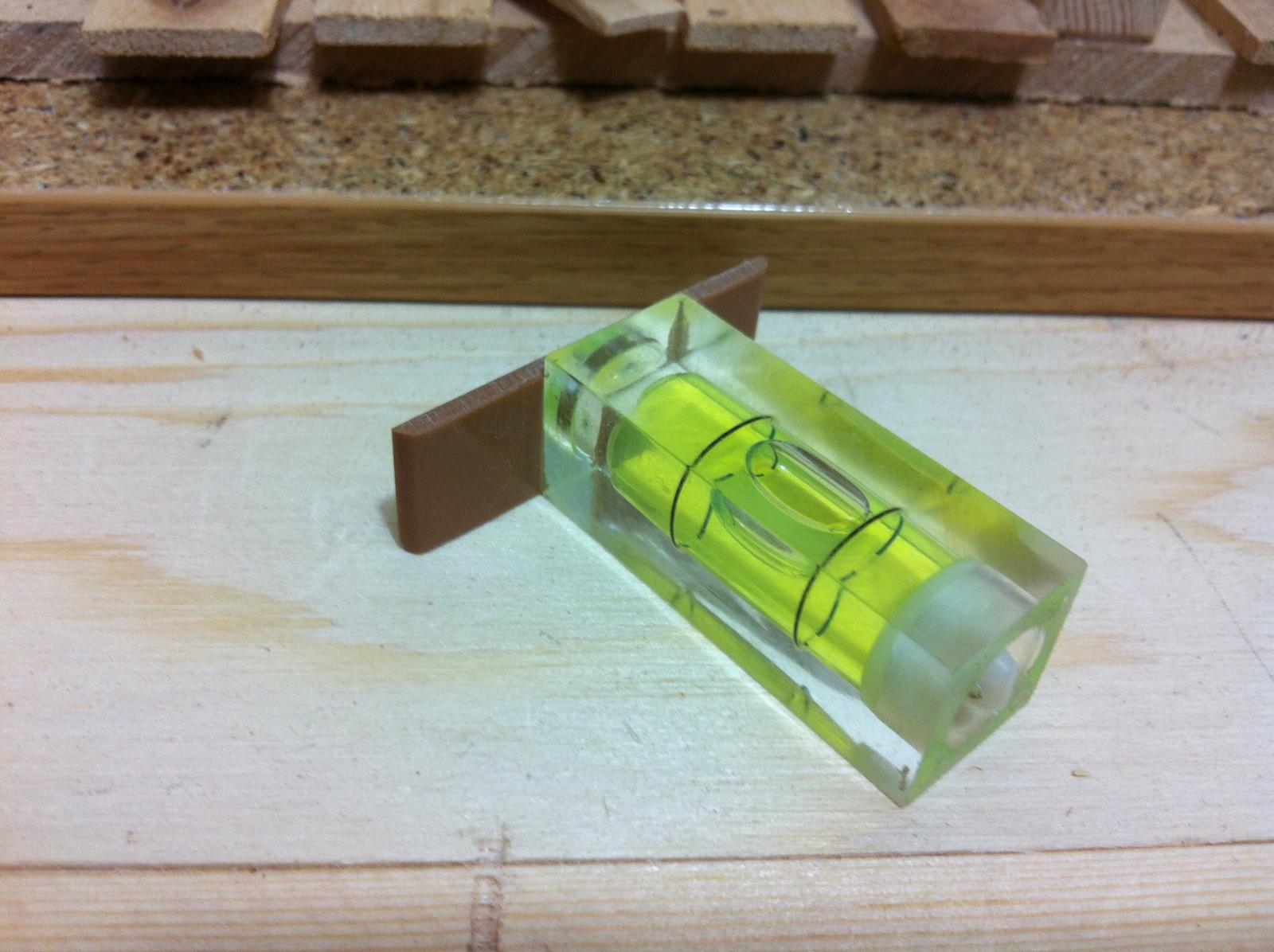
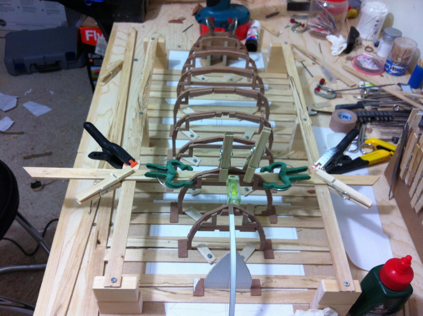
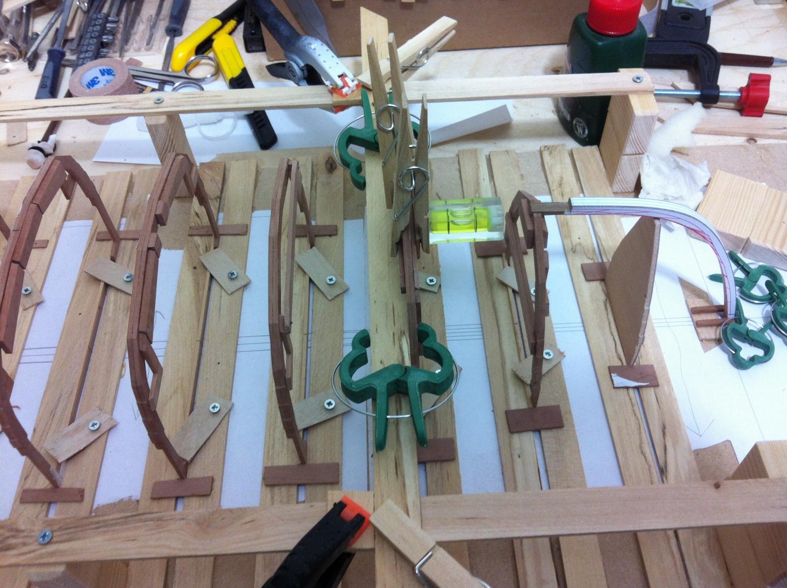
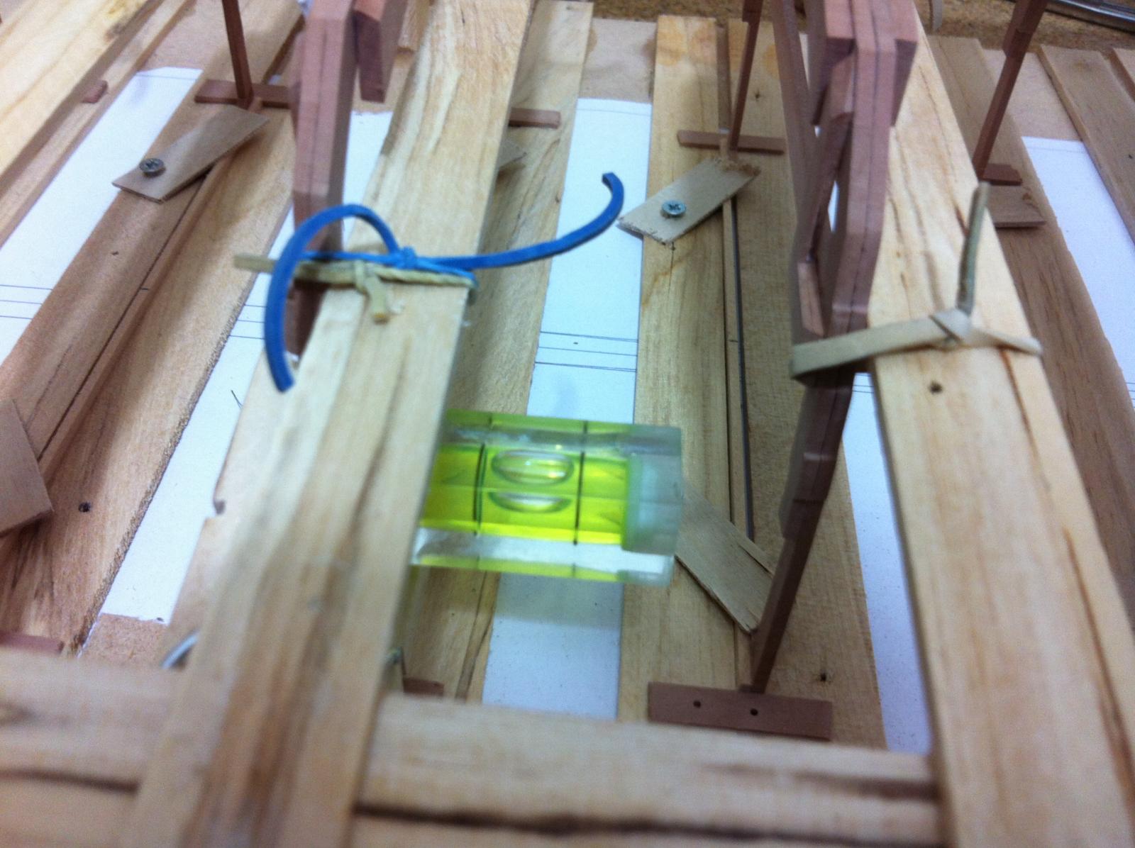
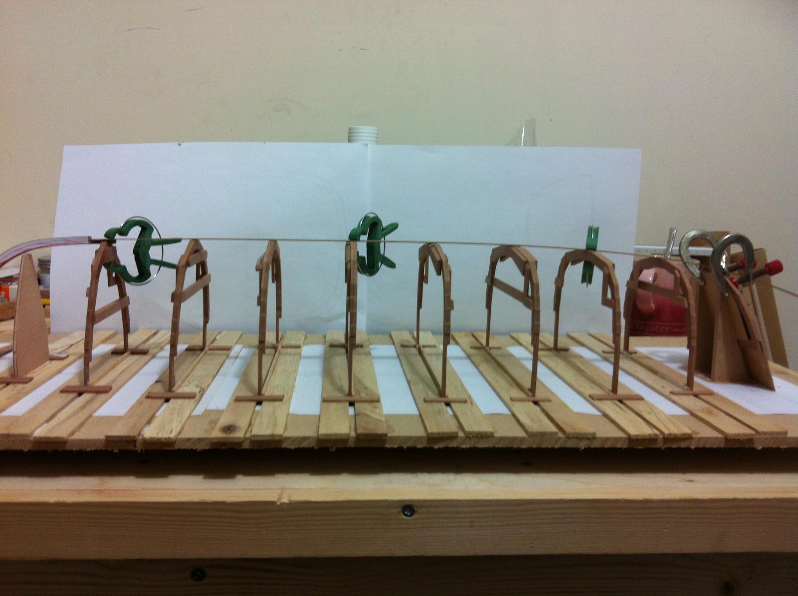
I tried to make sure the frames are vertical to the floor which is of course the top of my workbench. I modified a key ring sprit level by gluing it to a flat piece of plastic

I then started adjusting each frame, but something was wrong.


It took a long time to realise that my bench top was not horizontal by far. I had to use my modelling jack to square things up
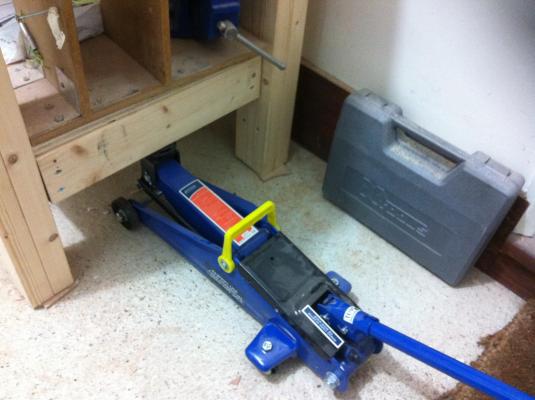
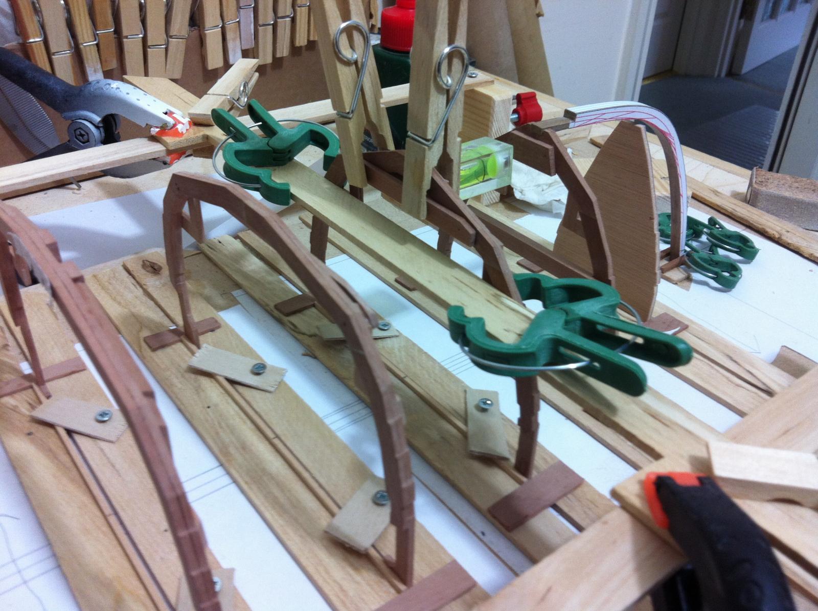
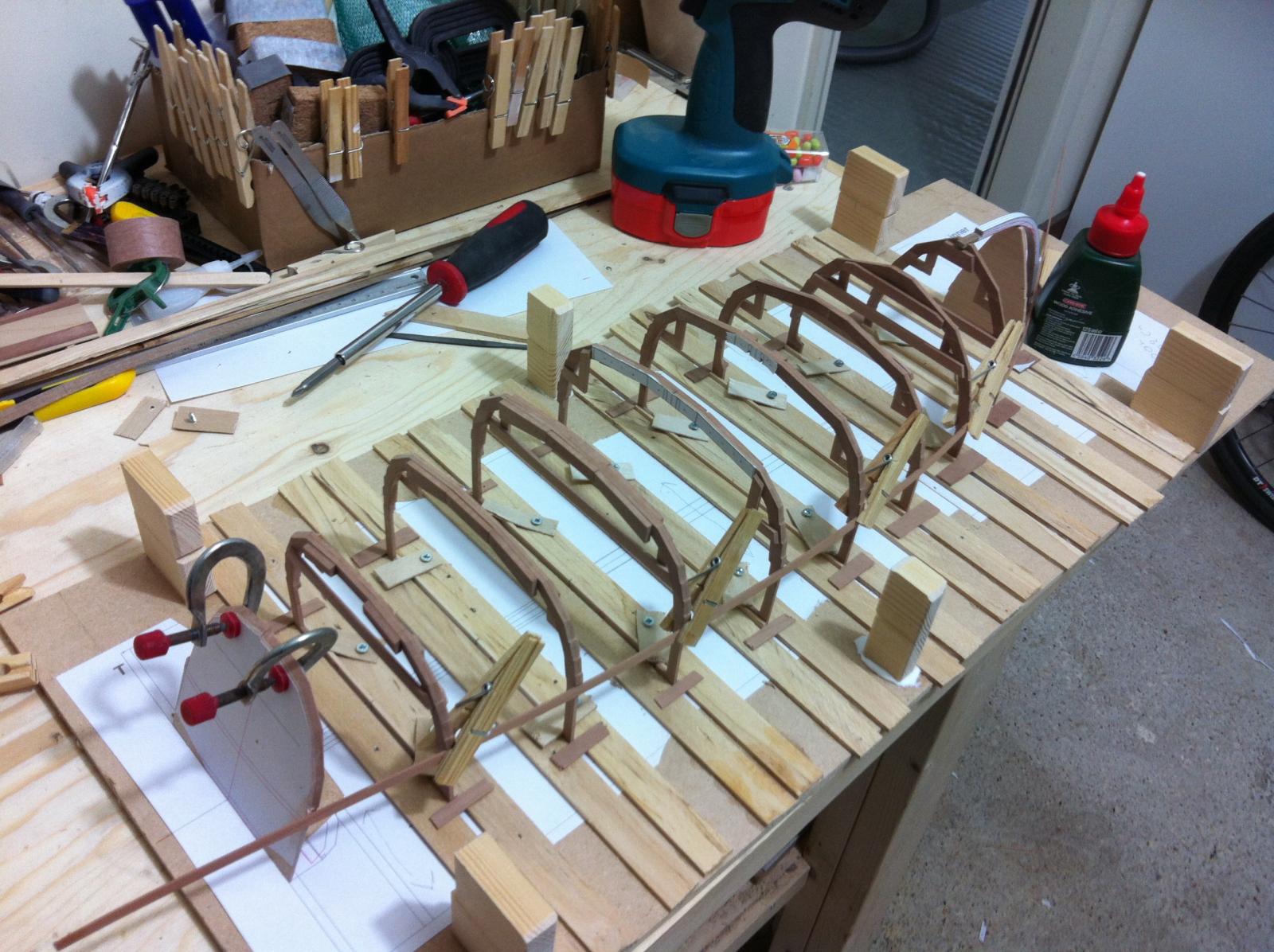
After this things went smoothly. I used rubber bands to attach the frames to the jig. The scaffold is screwed to the pillars so it can be removed and re-installed if necessary without loosing alignment.
I found a way to secure temporarily the stem. I also beveled the stem which was much easier than I thought.

The built is becoming too complex though and complexity is usually bad news. Anyway, I am ready to laminate the apron
- mikegerber, druxey, mtaylor and 1 other
-
4
-
Thank you all, your support is much appreciated. There are still many difficulties ahead!
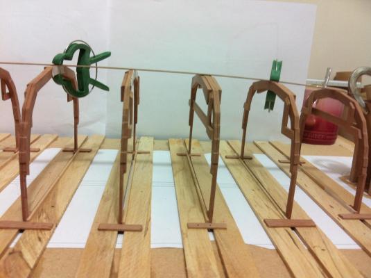
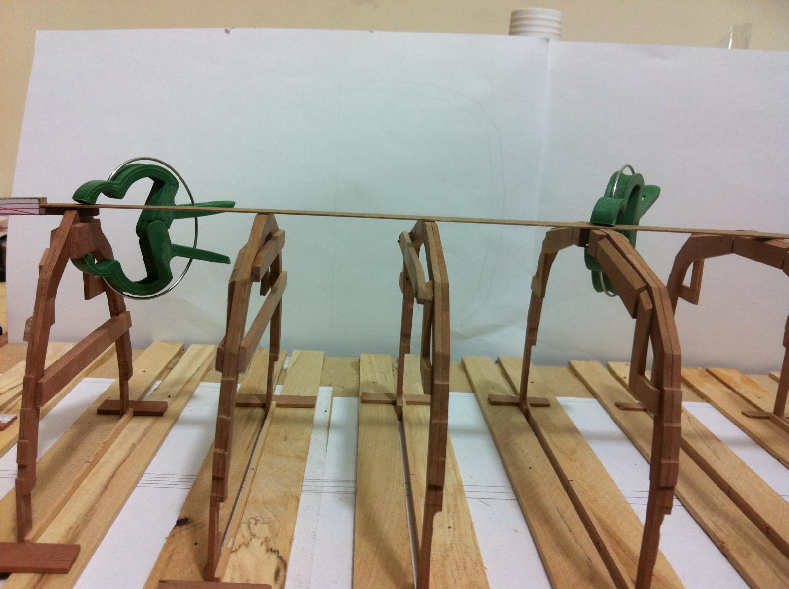
I got very worried yesterday, I test fitted the outer sheer clamp and it was way off. I looked at the CAD designs again and realised that indeed I faired the sheer line in all views, however due to the lapstrake and the planks overlapping and not staying parallel to the frame, the plank to be used as outer clamp in order to follow the sheer needs to bent not only along the beam of the boat but also vertically along its own width.
I did a bit of internet search and still the way the sheer line is faired is a mystery to me. It seems that all boat builders erect the frames and then just bent a batten that easily follows the sheer.
However the solution appeared miraculously today. I continued work on the jig and glued supports for the longitudinal beams of the jig. I also screwed small pieces of plywood to stop the frames from lifting. I tested again the sheer and somehow it was fine.


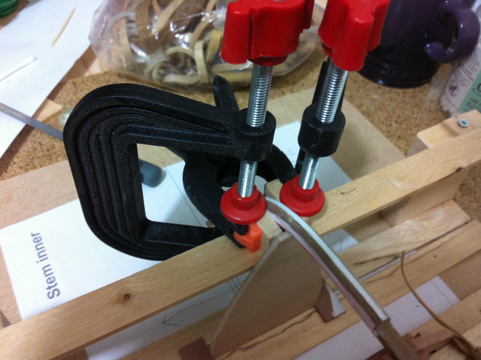
I also glued the templates for bevelling the stem. I am almost scared to do it but it needs to be done as the laminate is too hard to sand completely with files. The problem is I will not know whether the bevel is correct until the very last moment, when it will be impossible to re-do the stem. The sheer clamp runs true to the stem on the photos, I have allowed some excess to be trimmed in the end.

- garywatt, mtaylor, Jim Cricket and 5 others
-
8
-
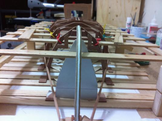
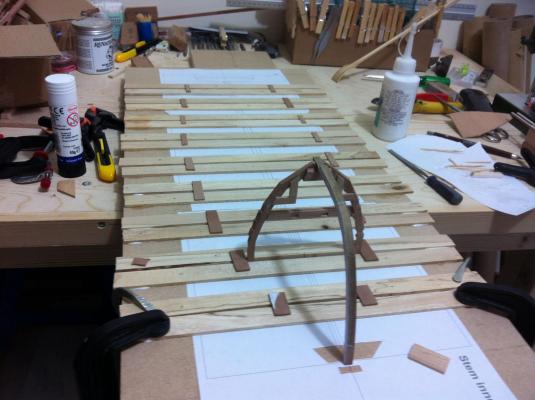
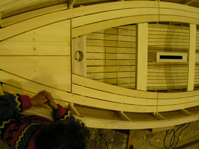
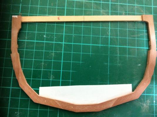
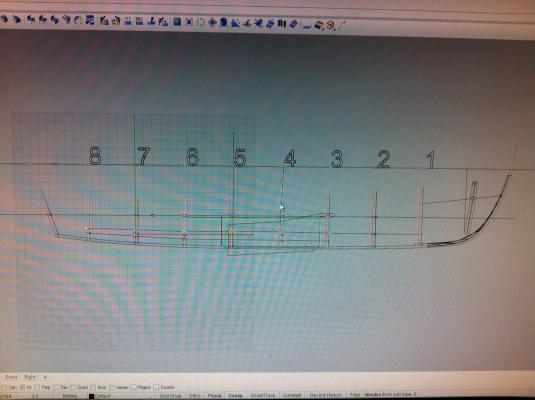
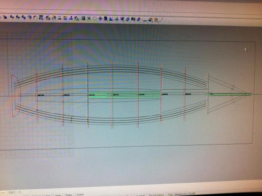
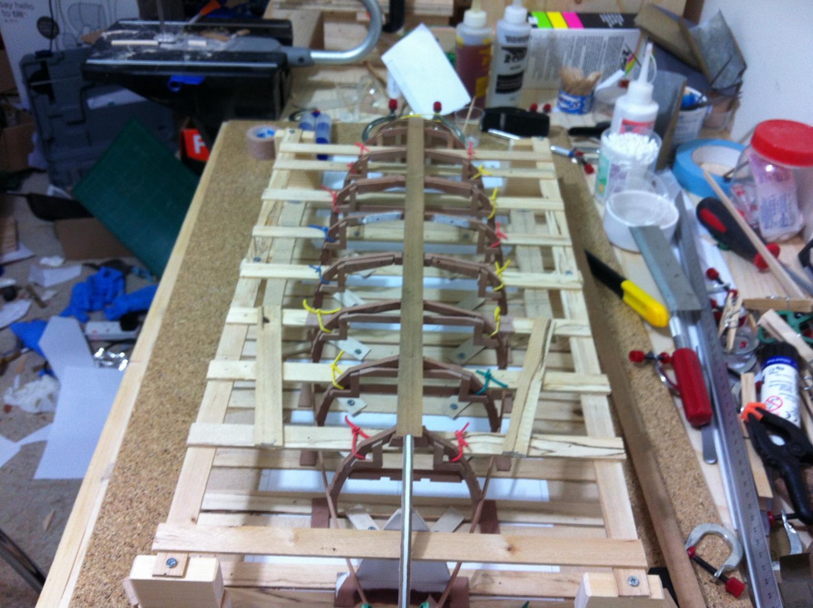
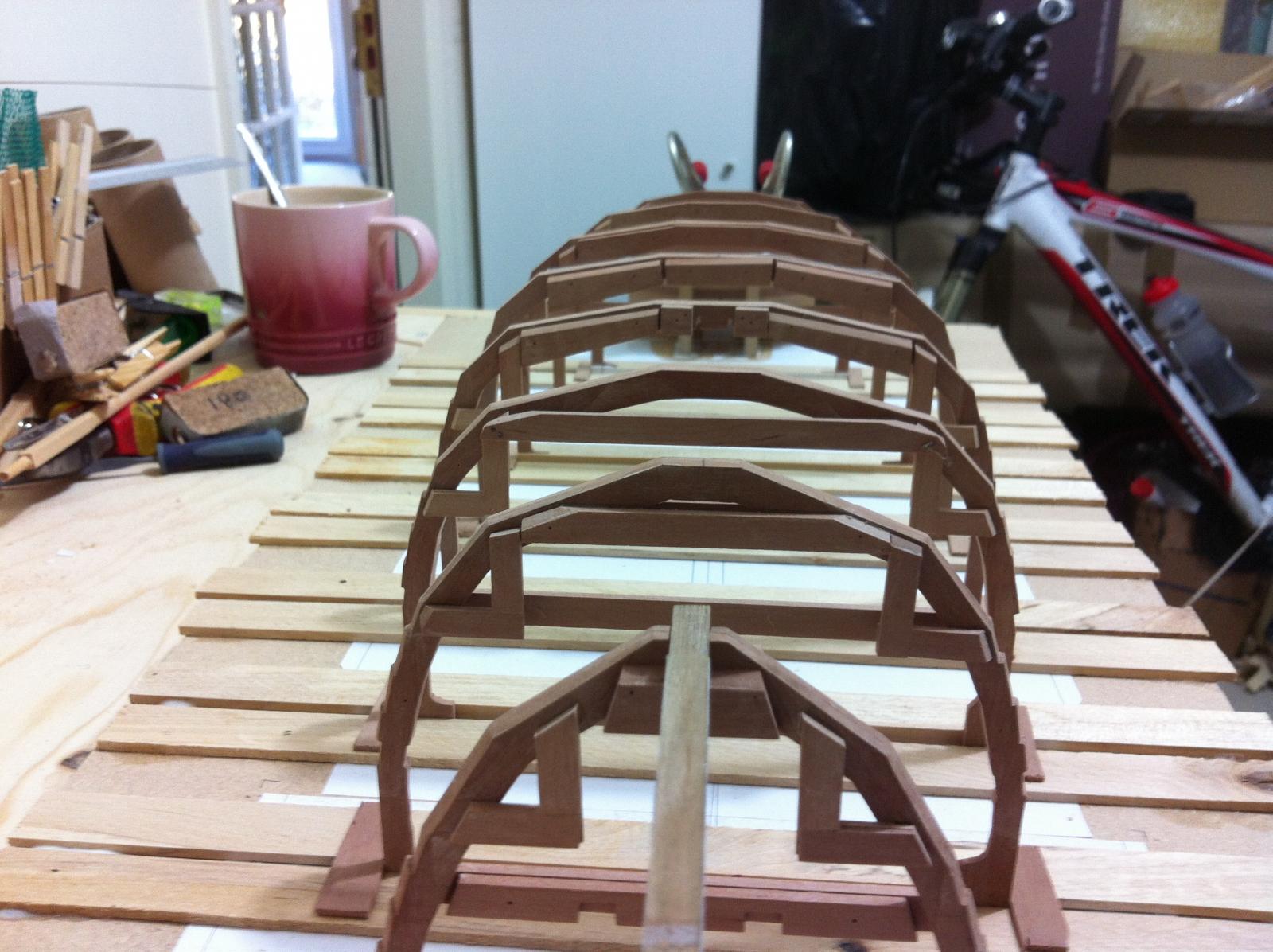
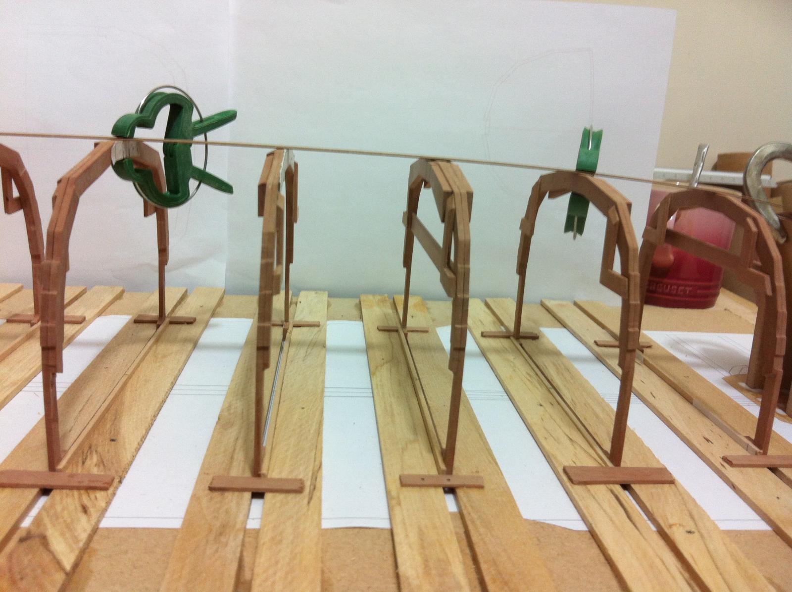
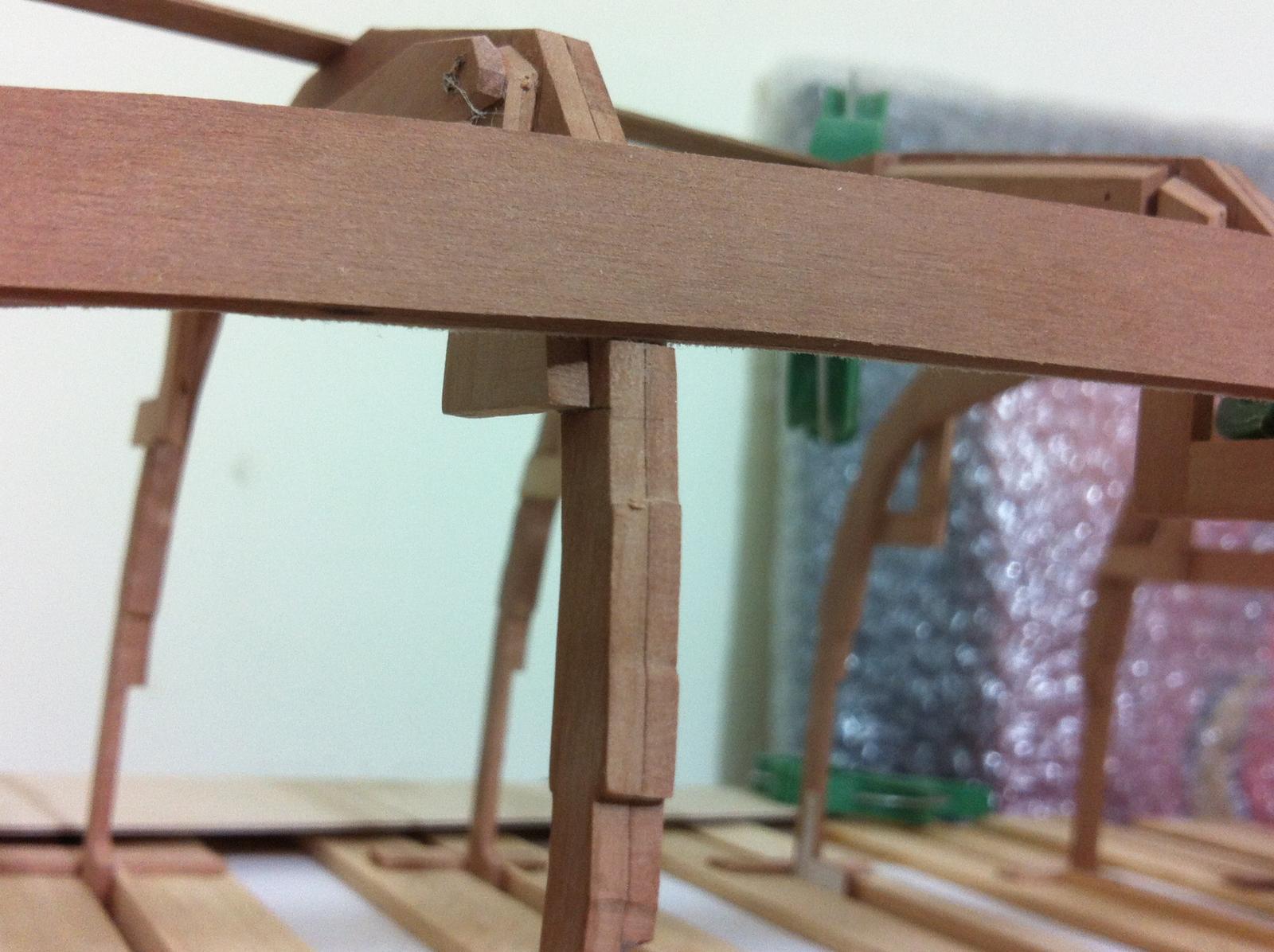
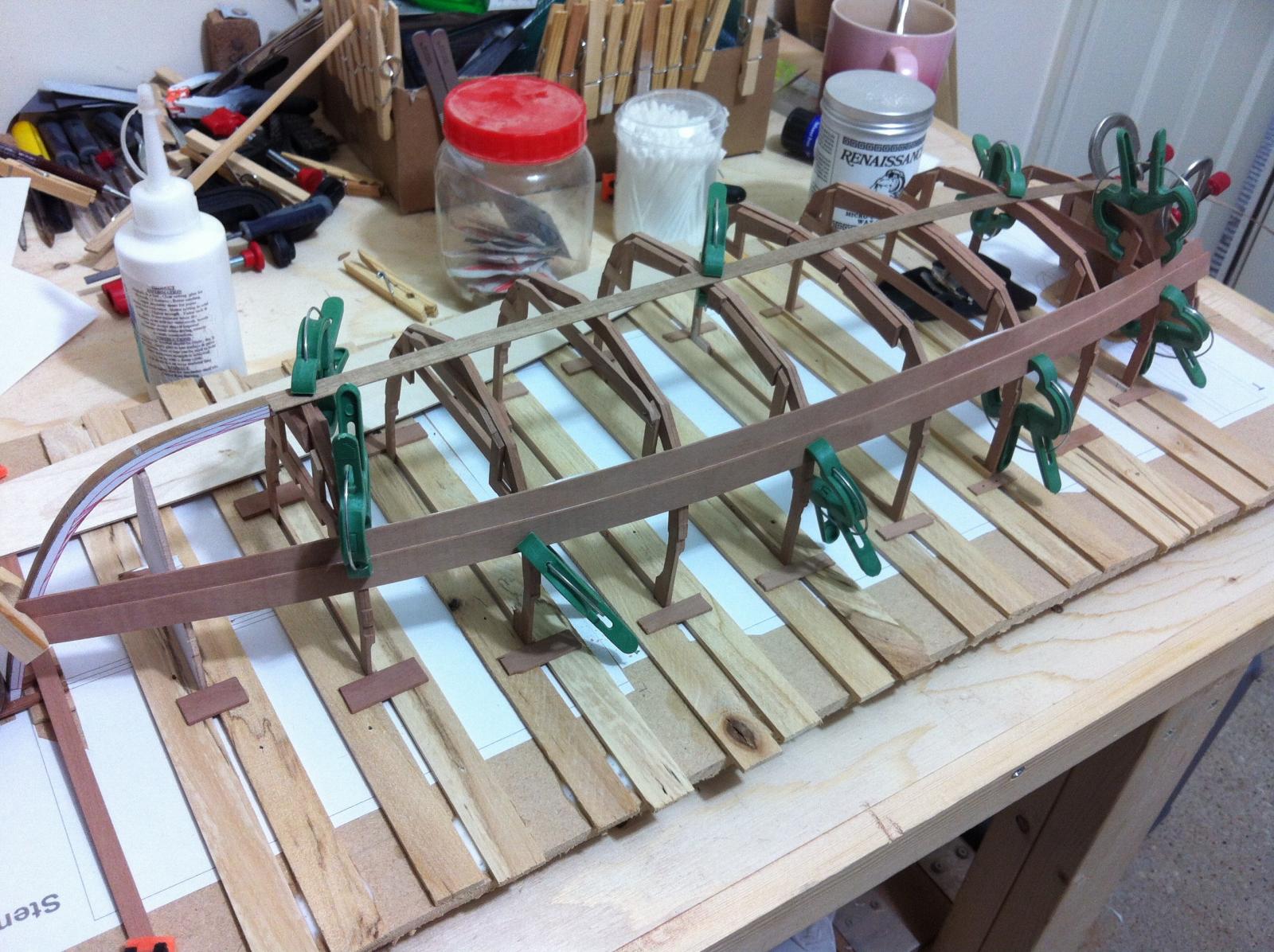
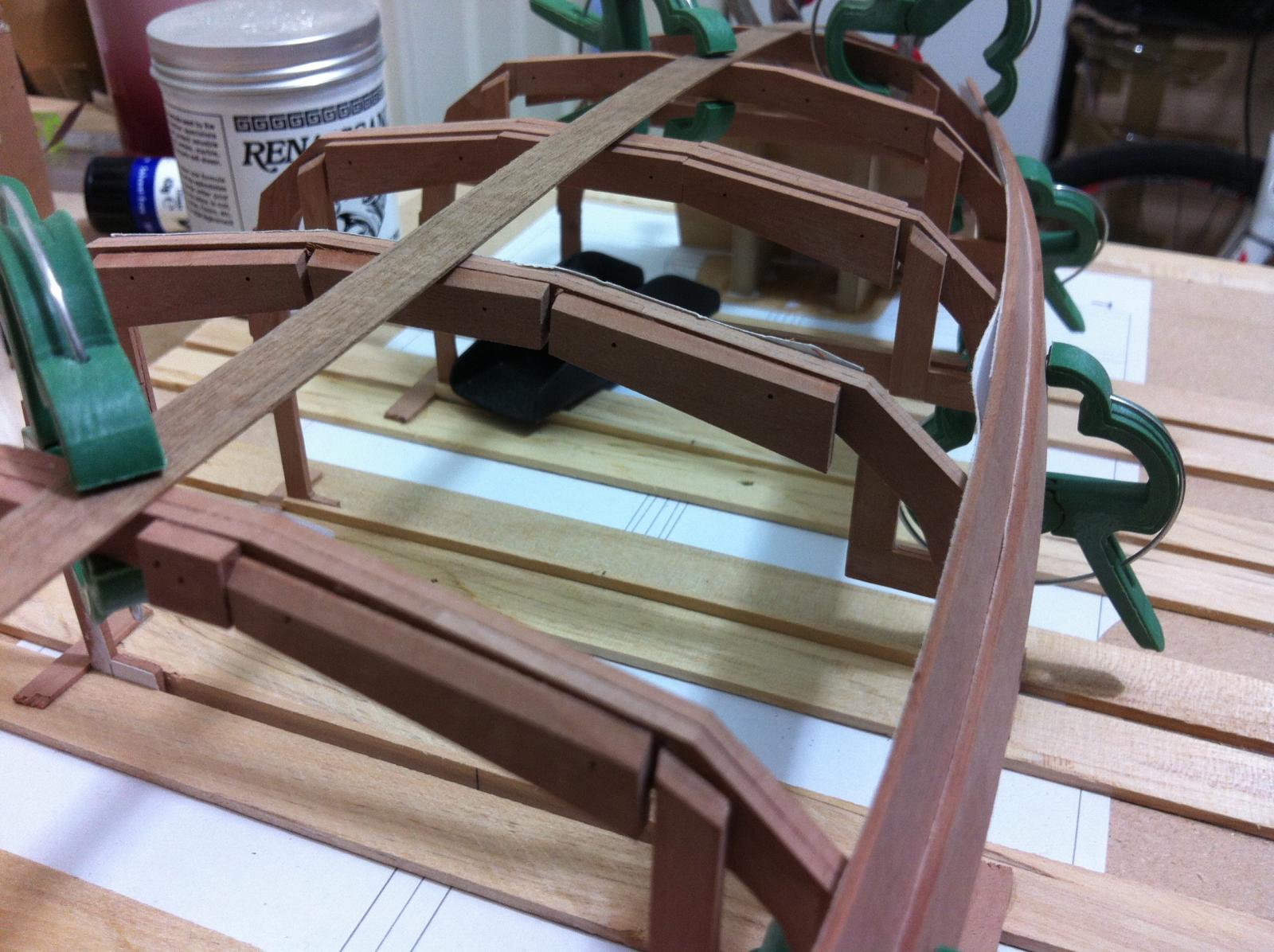
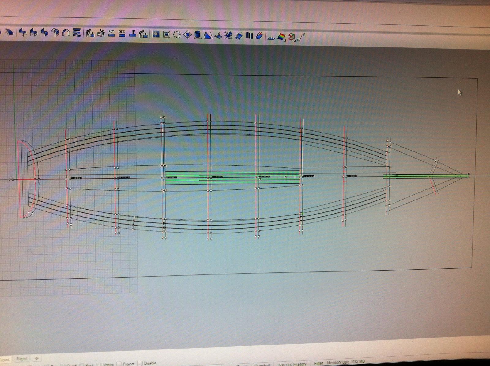
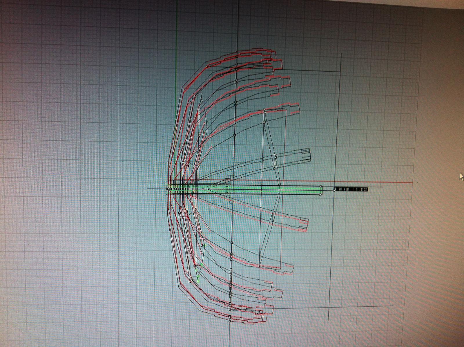
I think this might be a milestone. We have a first glimpse of the hull lines!
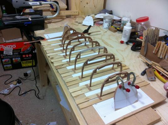
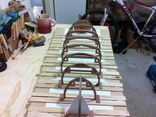

A strip shows the keel line, it touches all frames and I think is as good as I could ever get it.

I also attempted to fit one of the planks. This is the lowest plank, it is rough fitted as it will touch the lower strake plywood panel.

My first impression is that the plank touches all frames effortlessly and the bevels are correct, the notches on the frames are also at the correct heights, I am amazed with the accuracy.


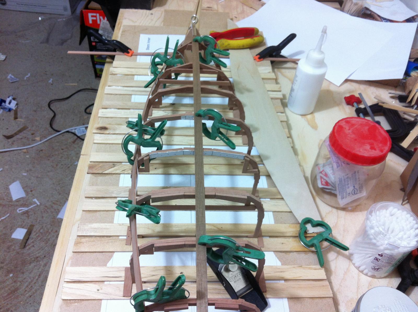
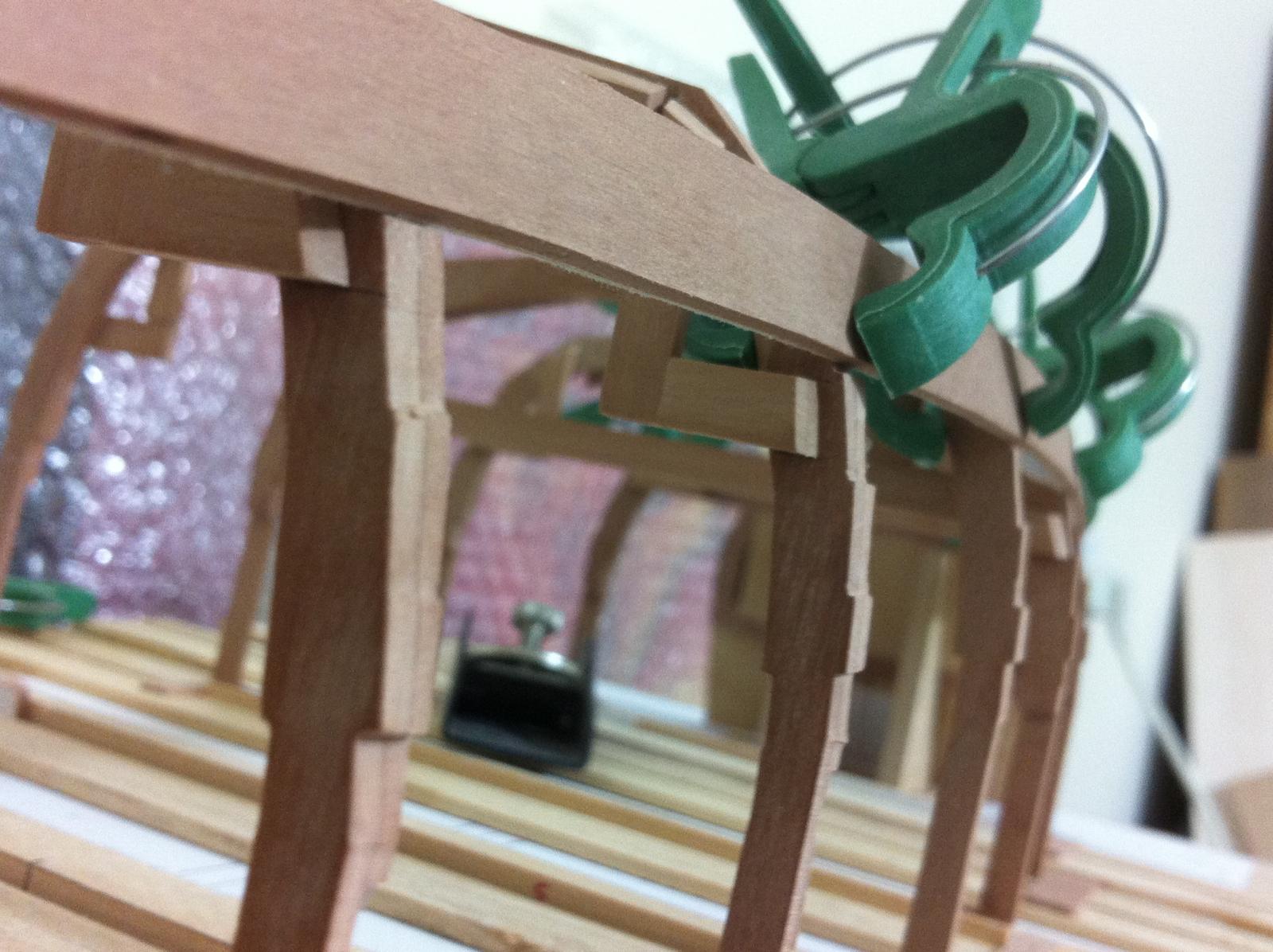
I added another plank, again it seems to fit ok. i am very happy that the two planks stay in contact throughout their length.


Now the more delicate work begins, too many bevels and plank overlaps to tackle!
- michael mott, mtaylor, SailorGreg and 9 others
-
12
-
The jig is progressing well. I plan to add later on longitudinal beams on each side at a height from the baseline and cross beams, 2 for each frame. It should be reasonably steady.

I need also to secure the stem and fine tune the bevel of the temporary mold at station 0 that later on will be replaced by the cant frames.
The centerboard case is also progressing and coming out very nice, I think it will be the best part of the boat!

I am certain the next big difficulty will be bevelling the apron and the stem to accept the bottom plywood panel which is essentially the garboard plank. The apron will have a thickness of 3 mm so it cannot be beveled like the keel of large boats. I also plan to laminate a false stem.
-
Grateful for the support Patrick! I agree with you, curved blade oars are nicer and probably the next ones will be easier to make but I need to find a way to ensure consistency. I should also try a flat one and see how it looks. Anyway, I will change focus for now and allow time for ideas to ripen.
My drill is here! It is really well made, spins very true, is quiet and easy to use. Highly recommended.
I finished glueing all the beams that are attached to the frames and sanded everything down to 400 grit

I planned to apply wax to all surfaces prior to assembly but it did not work very well, the surfaces are very complex and there is a risk to contaminate the surfaces that later on components will be glued. Also, sanding had produced some fine whitish streaks on the wood that I thought the wax would cover. This did not happen though. I am not sure what the cause is, I suspect these are scratches due to not changing the sand paper as often as I should. They are not a huge problem though, it still looks good. Another problem to sleep on.
The time has come to laminate the apron and for this all frames need to be erected. So I need to make some sort of jig. I do not have the equipment to produce the jigs I see the master modellers use so I have to improvise.
I have a lot of this nice wood which is really a fence bought from poundland. I did a bit of Zen and I think I can make the jig work.
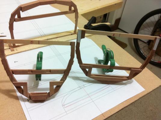
Another picture of frames No 1 and 2. I am happy with the alignment of the components although I will not really know until the final assembly
- Mfelinger, captainbob and mtaylor
-
3
-
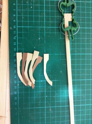
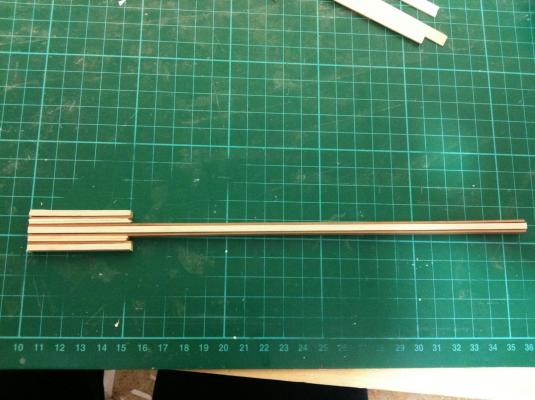
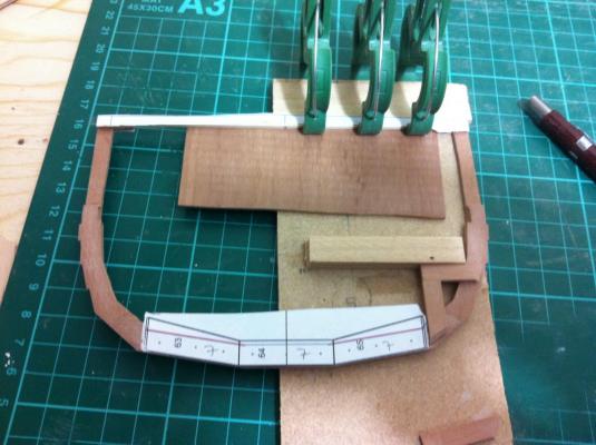
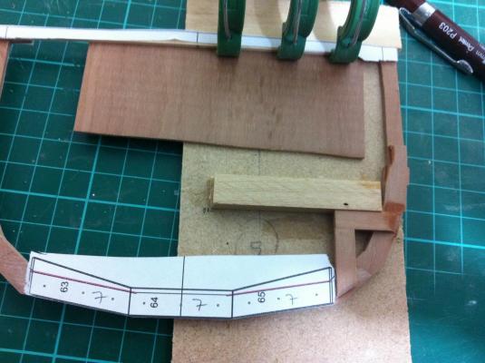
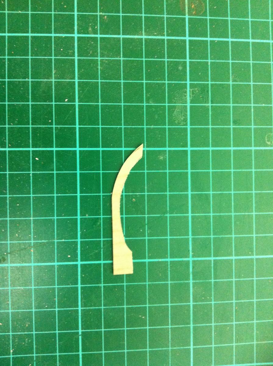
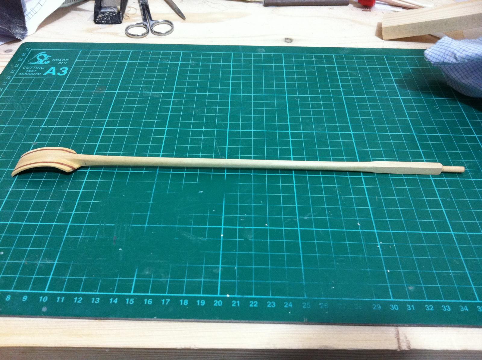
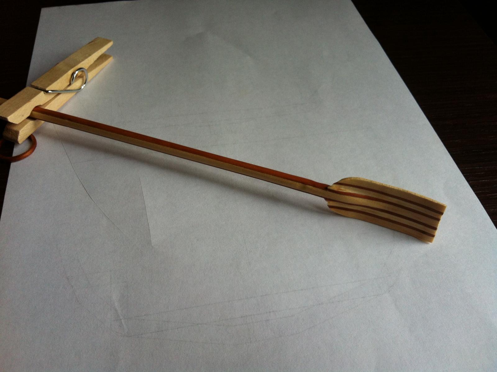
I had another go today making the oars. I watched a video on you tube of a company making high end oars and copied their method. I also found out the maths behind the length oars should have and for this boat its 32 cm, much longer than the first attempt.
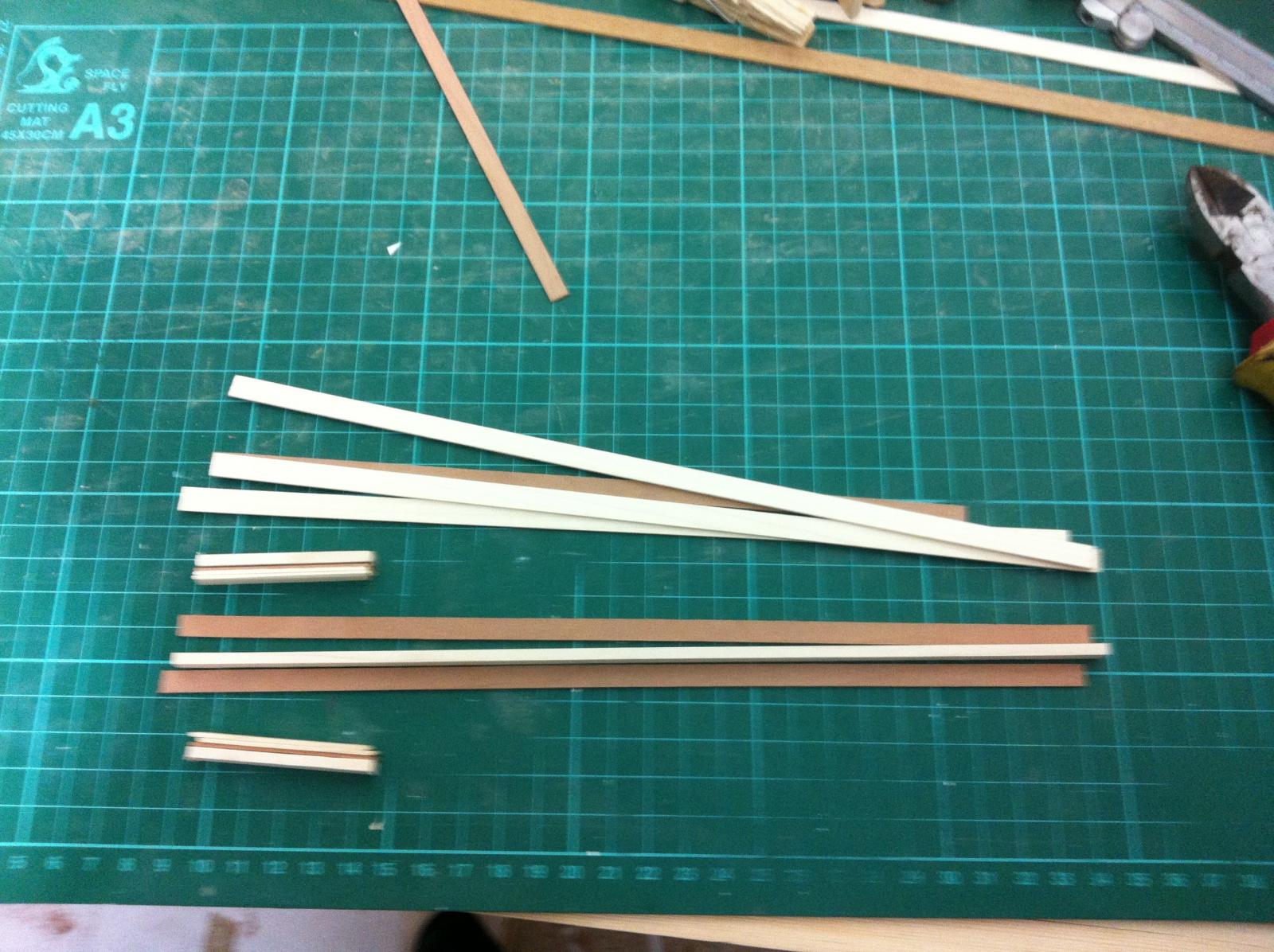
First I made a rough pattern of the curve of the blade from scrap plywood.
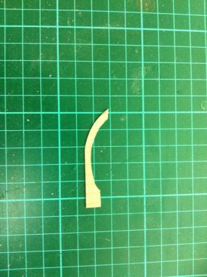
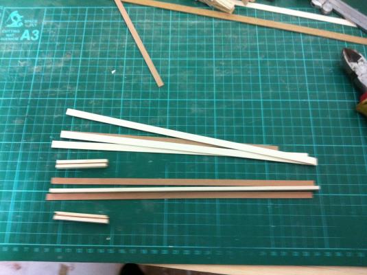
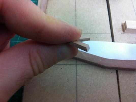
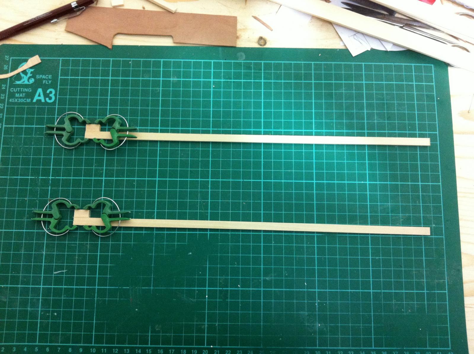
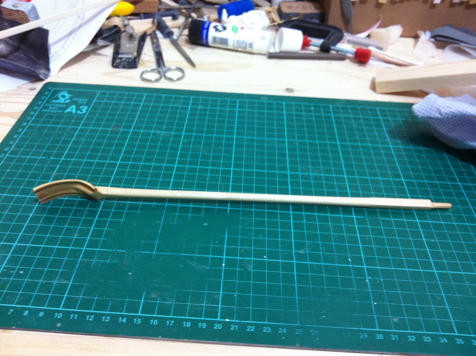
Then I glued a small piece at the end of the long pieces that will later on be glued together. This because the end of the curve goes beyond the width of the strips. I used lime for two reasons, because it sands easily and also I have lots of it.
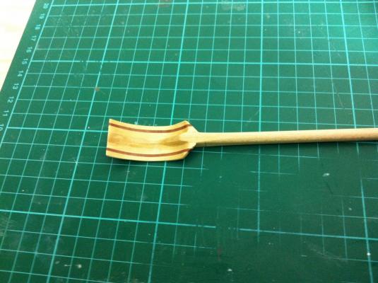
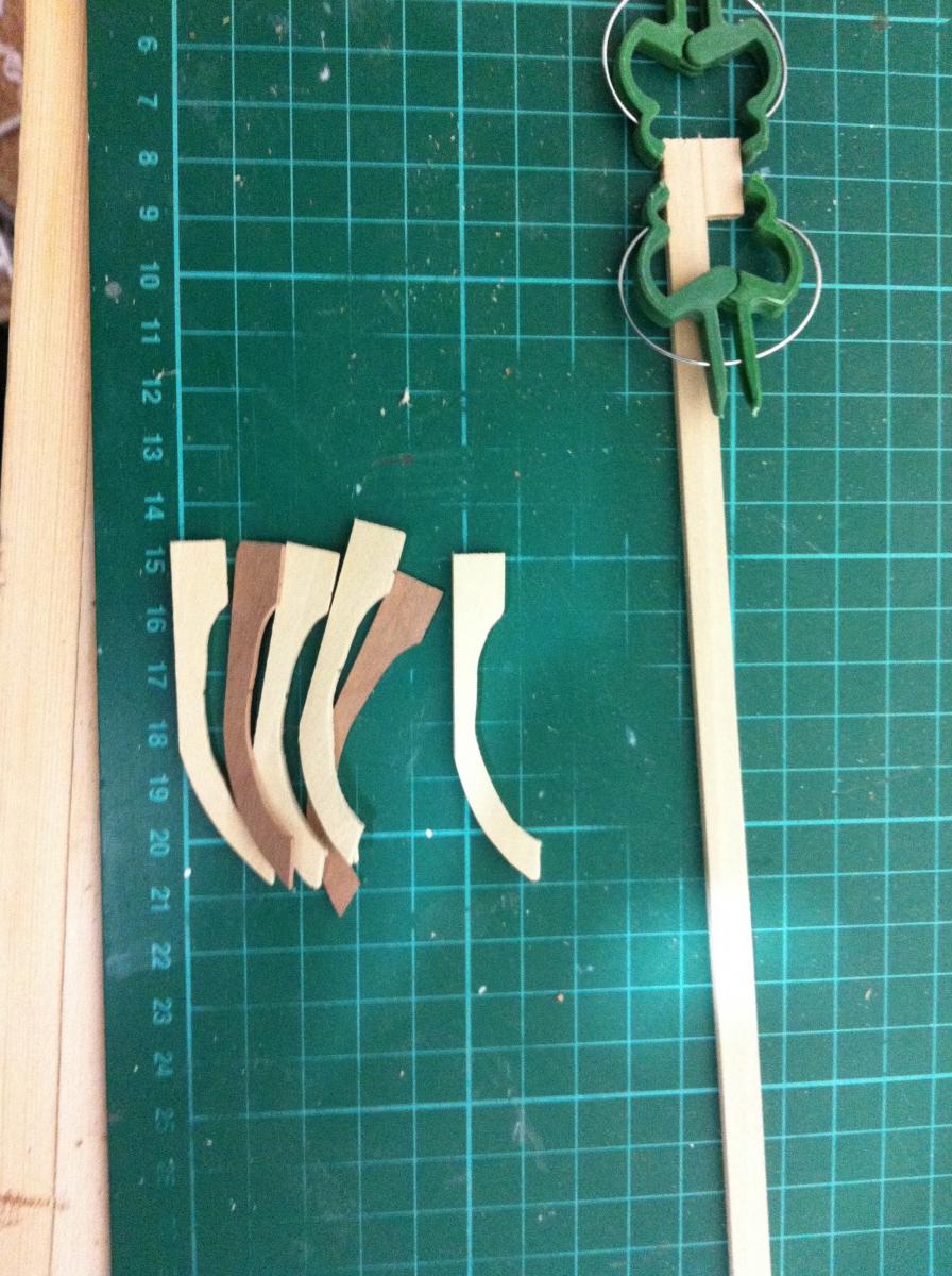
I then made some more pieces from the pattern. The darker ones are pear, but these are cut at an angle to the grain so that when all are laminated it will provide some strength against breaking.
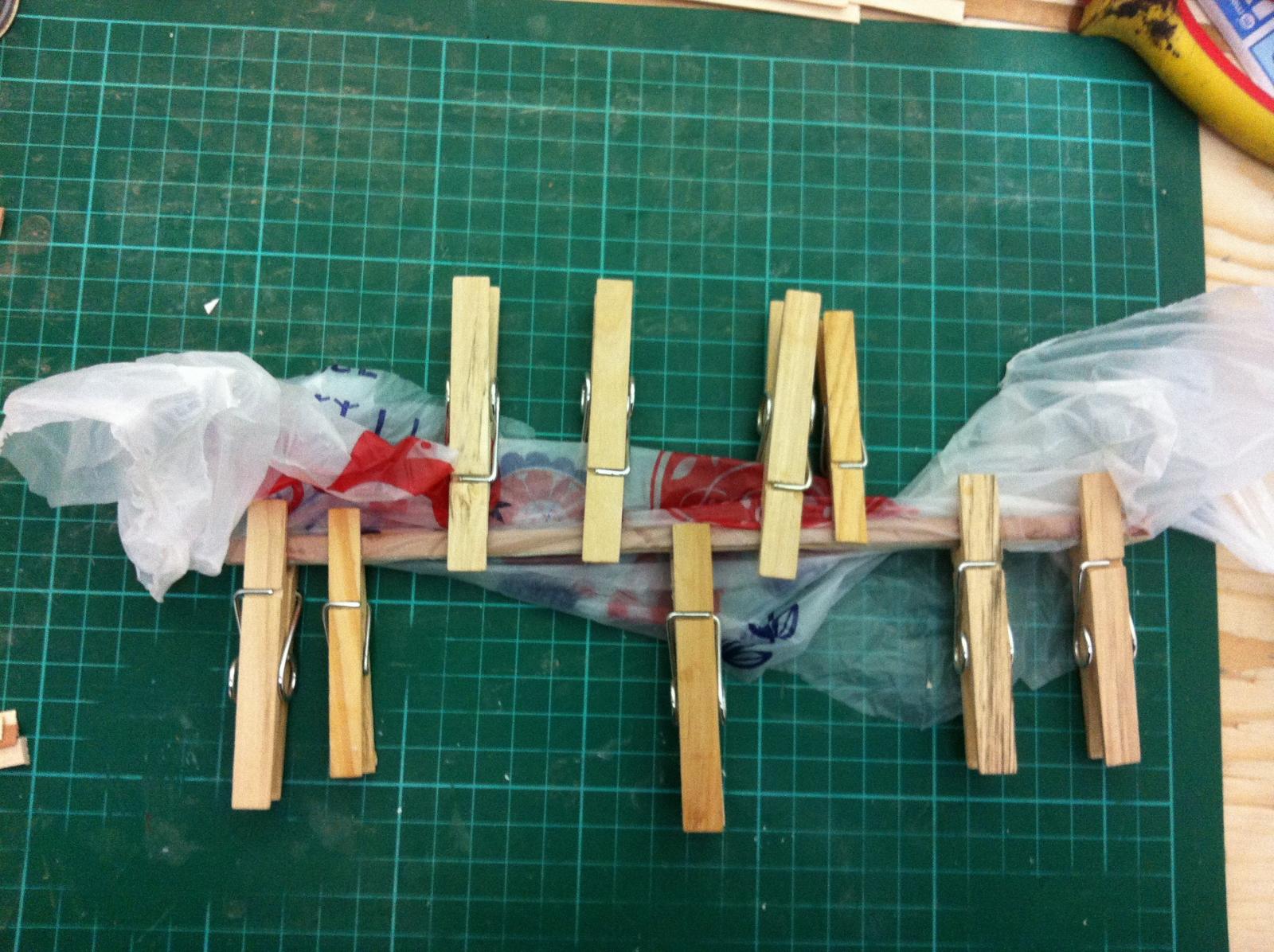
All are glued together
And glued again
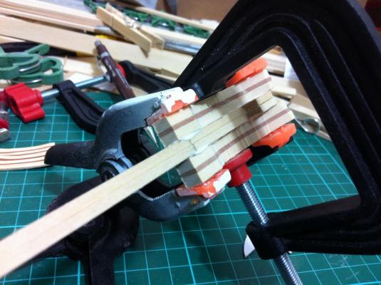
This is how it looks before the sanding spree
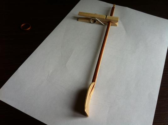
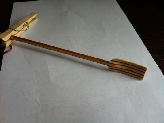
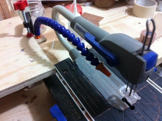
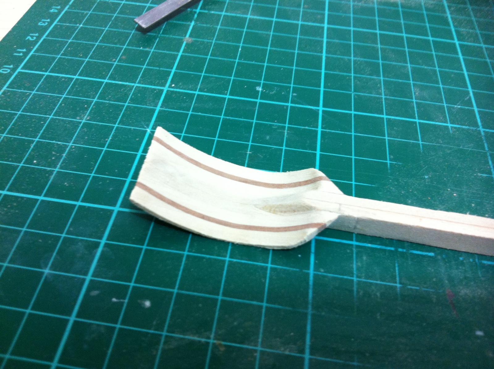
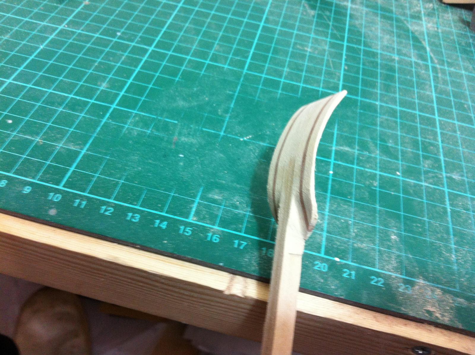
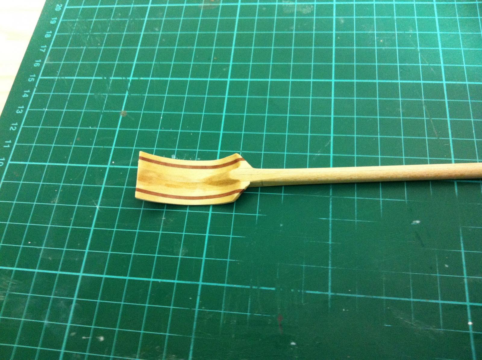
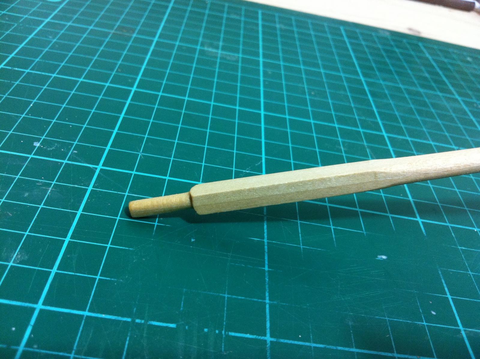
The corners near the shaft where cut off and then carefully the oar was sanded into shape. The improvised table for the Dremel was very useful.
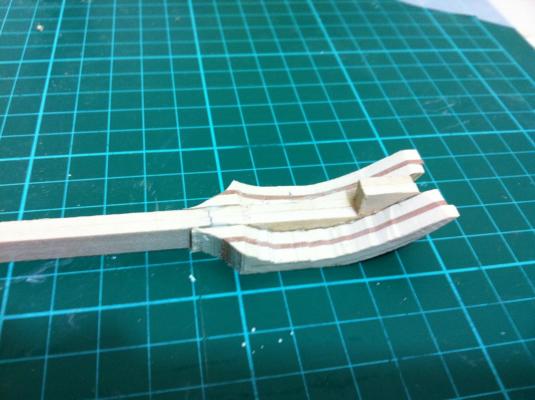
The blade was shaped first and then the shaft.


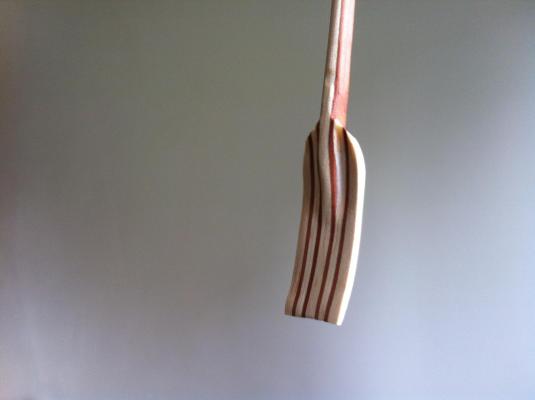
This is how the oar came out, it certainly looks better.
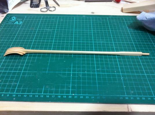


It took half a day to make one oar and the chances of all 6 coming out reasonably alike I think are slim. Might be better to go for flat ones which should be easier to make.
- IgorSky, Vladimir_Wairoa, Mfelinger and 4 others
-
7
-
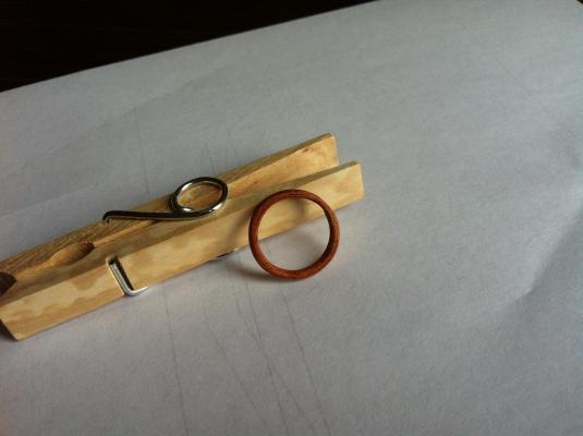
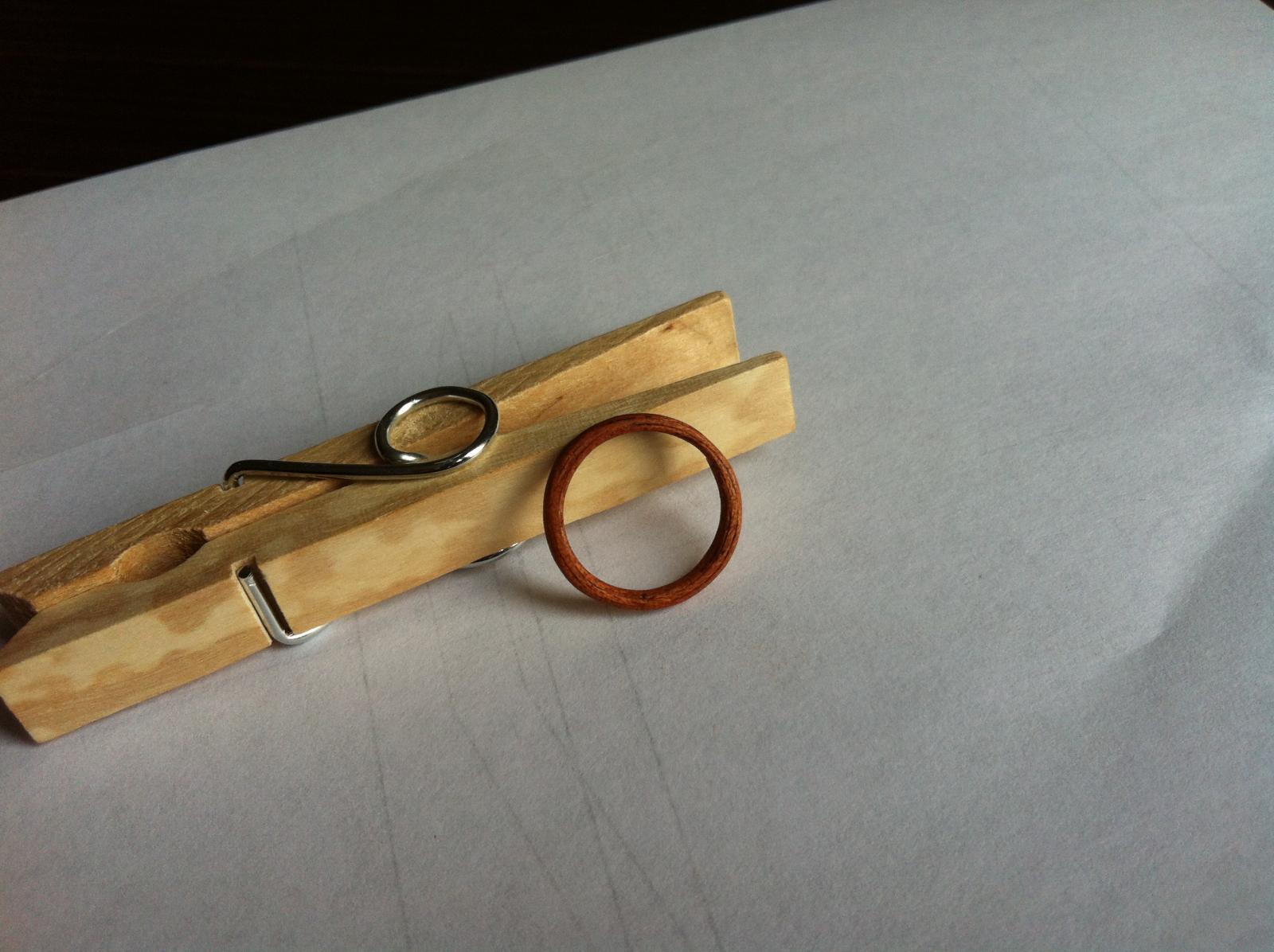
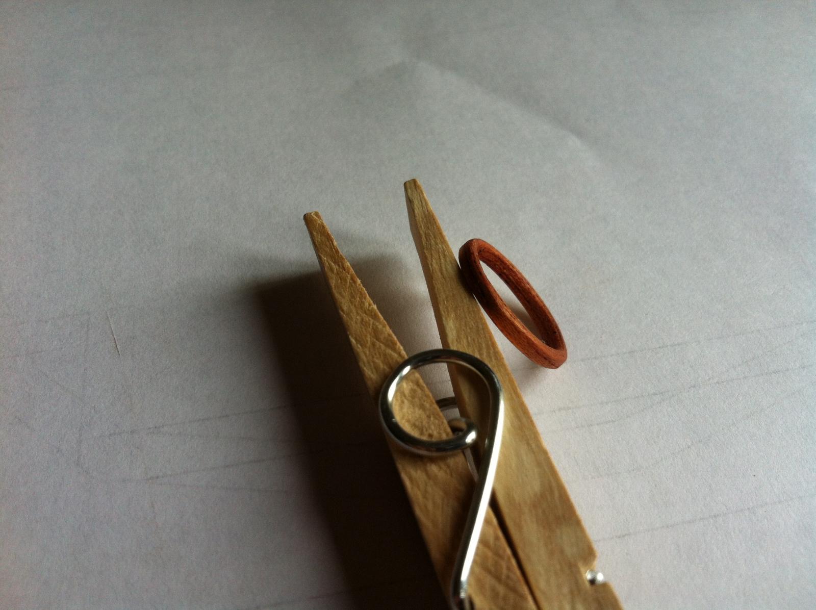
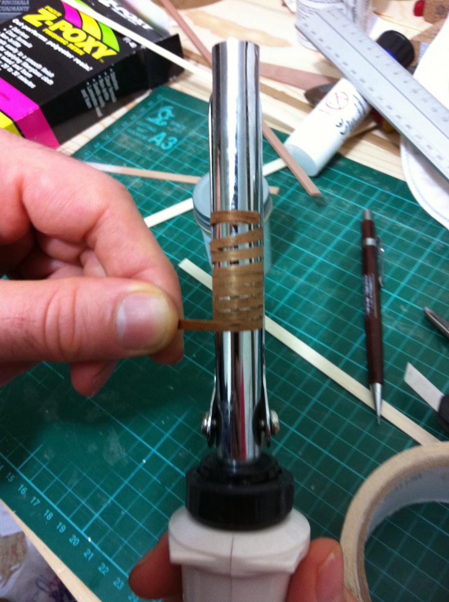
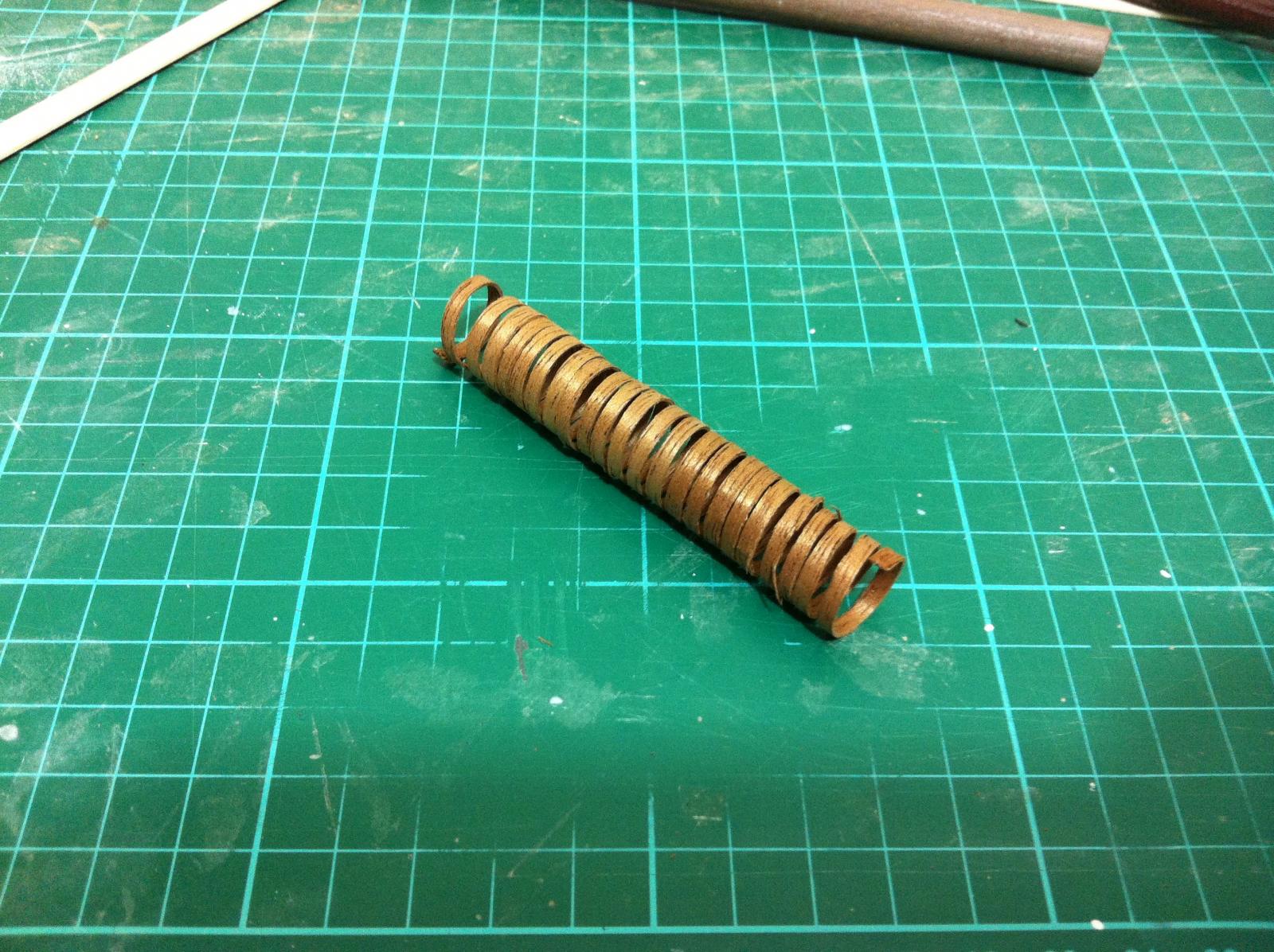
I experimented with the hoops and oars (good title for a boating magazine). The hoop came out alright, although mahogany is a poor choice I think as it splinters a lot. I used it just because I had a few left over strips but I might order thin strips of another wood. The hoop on the photo has been sanded to 400 grit and had a coat of Tung oil.

The oar was much more challenging. The end result is horrible but I think that it could be done with a lot of patience, planning and attention to detail.
- Mfelinger, mikegerber, garywatt and 5 others
-
8
-
-
Gary, I would like my CAD drawings to be put to good use rather than stay buried in a hard drive but that's for later, I would like to see first the project completed which will validate their accuracy.
Back to the boat, work has stopped as I am waiting for the replacement drill press. A lot of drilling is necessary at this stage and I resisted temptation to use the hand drill, the accuracy of the machine will be far superior.
A side project will be the making of oars and this is a project I was actually looking forward to. I am sure there are some guidelines regarding length etc but a quick search on the net did not produce a lot so I made an uneducated guess. I think a curved blade configuration with laminated maple and walnut would be nice, finished with Tung oil and Renaissance wax. I laminated a few pieces for oar No 1 (test oar if it goes wrong).

-
There are many CAD programs Gary, I use Rhino 5 because this is the one I had access to. I think they all are similar but be advised they can be very expensive, Rhino I think might run close to $1000. You also might need someone to get you started ( I had a friend who is an architect) and then on you ll figure things out yourself. I also tried some of the free ones on the net but did not like them.
Regarding the blower for the saw, I now attached a lathe hose and the whole thing works very well.
-
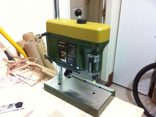
Today was a challenging day. The drill press arrived but was faulty so had to go back. The proxxon unit though looks very solid and ideal for modelling. I really liked it.
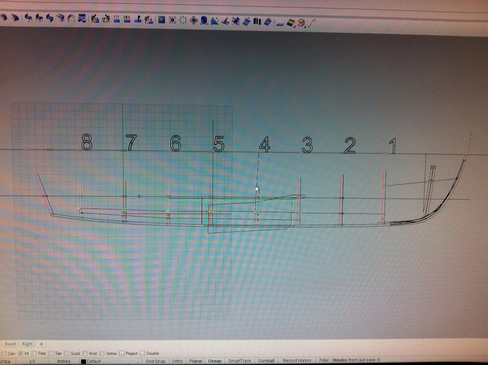
Back to the boat, I was working on the deck assembly and realised a big problem. As it stands the main mast has very little support.
Tad in his plans positions the main mast at station 0, where the cant frames are.
This position looks to me too much forward and indeed the US team positioned the mast at frame 1. However, studying the photos it seems they used very thin profile wood for the beams and also secured one side of the mast partner to the side benches. They obviously knew what they were doing but still I wonder how the mast can cope.
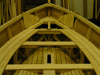
Since I changed the thwart arrangement I cannot copy their design. I like the position of the main mast at frame 1 though. So back to the computer to arrange the beams for supporting the mast and the deck. The main problem are the cant frames and it was incredibly difficult to find an arrangement that would actually work in a full scale boat. Also, the deck is not horizontal but has a slope which added to the complexity. All beams had to be notched to accept one another.
I am very happy with the result, it looks super strong and I am sure it would be fine in a real boat. Building to these plans of course is another issue.

- qwerty2008, mikegerber, archjofo and 2 others
-
5
-
It works brilliantly Garry, it has become my main tool. Still on the original 120 grit paper!
-
I think you are right Remco, turpentine should work better but compared to low odour Mineral oil which in essence is odour free it is very unpleasant to use. Either way, just rubbing the wax with cloth I found works brilliantly.
Pure tung oil is great, really brings out the beauty of the wood. I think though it will darken the swiss pear I am currently using.
How do you buff the waxed surface?
-
Your support is much appreciated Patrick, especially as time is running out...there is a little one due in 6 weeks and undoubtedly work will slow down to a halt.
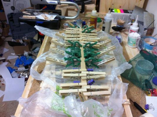
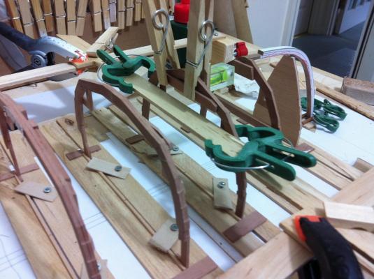
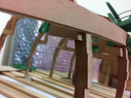
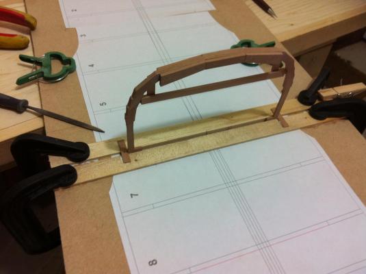
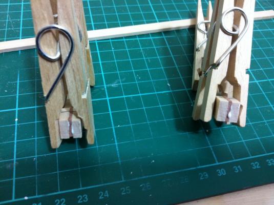
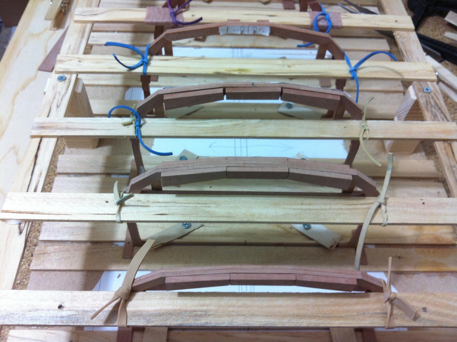
I will present briefly the process of glueing the knees. First everything is sanded to 400 grit.The paper pattern is used only for the lateral adjustment as the height will be set by the jig.

I could not resist bevelling the ends of the knees although I think they might not be visible
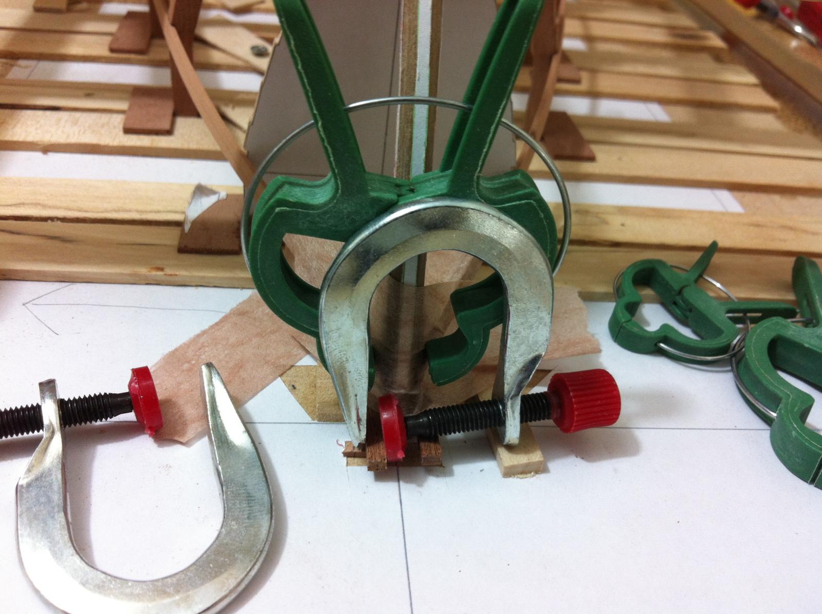
The contact areas are marked on both sides to apply glue appropriately. The green clamps are used in gardening, I find them very useful and costed me £1 for a pack of 20! Excess glue is carefully cleaned with water.

The lap joints in the frames came out nice, the frame is only sanded, when the wax is applied it will show much less I think
All knees and some of the beams supporting the thwarts are ready. I have some 1 mm walnut dowel which I am thinking of using as nails or I might save it for the planking and use toothpicks instead.
Before I do any more work I really need the drill press, until it arrives I will work on the floor and deck arrangements.
-
The work is progressing well and many components are ready to be installed. I still need to design on CAD the deck arrangement with the mast partner and beams, the floor arrangement and aft thwart at the transom.
The planks for the benches are ready to be cut, I am thinking of improvising some short of sanding jig which will have the shape of the benches to assist in sanding the inside part of the planks.
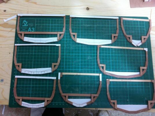
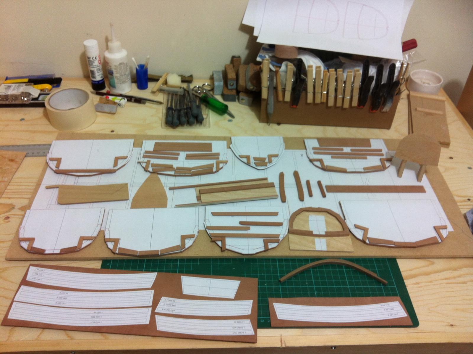
This is an overview of all the components already prepared, not including the planks

I also made the centerboard, it should be made of steel but I think a common alternative is a laminate of wood core sandwiched by plywood and fiberglassed over. This is what I did minus the fiberglass. It still needs some sanding and painting. It came out super stiff.

I also did some work on the centerboard case which is coming out really nice.
I try to make sure everything is sanded before assembly and that excess glue is cleaned immediately. All joints so far are very clean.

I also glued the knees for the frames 1 & 8 using the jig and things look reasonably aligned. It is not a really solid process but it works so I am sticking to it for now. Everything is sanded before assembly and since I will be using Renaissance wax no other preparation is needed.


I have ordered the Proxxon drill press which will be I think extremely useful. If I had it earlier, assembly would be much easier and accurate. Lesson learned.
- aykutansin, mtaylor, druxey and 3 others
-
6
-
Do you polish it somehow Brian? My test pieces show some streaks when held against the light, not too much though. I tested buffing with a buffing wheel and the Dremmel but it does not work great. Polishing with the hand does not feel the same as with other waxes as this dries very hard.
-
Progress has been slow as the built is becoming more complex. I have decided to add all the knees and the beams that support the side benches, thwarts and deck to the frames before assembling the hull. In the full size boat this would be done after planking but I think it would be very difficult. I will also need to make and add the centerboard case and all the supports for the floor. This is massive work and it is a bit strange, months of work and nothing to show but a glimpse of the hull lines when test fitting the frames! I think this is a case when you need to treat every small component as a model of it self.
Of course all these will need to be finished prior to installing. I am sold on the Renaissance wax which excited expectations in my testing.
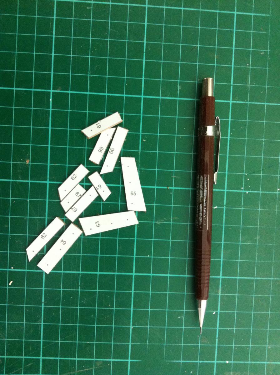
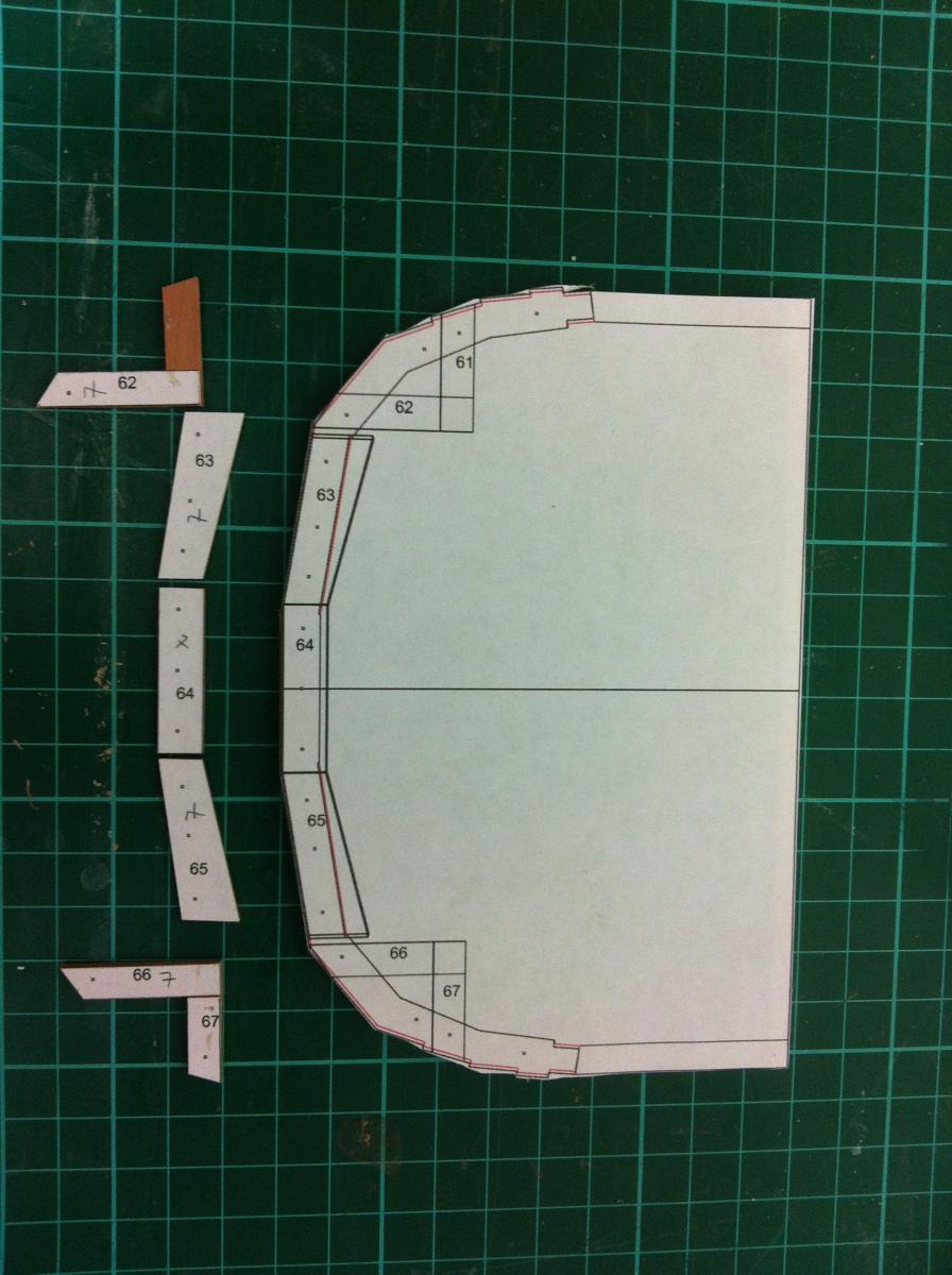
Back to the computer then. The next photo shows the template for frame No 7.
The knees will be made full lap which is a bit of a challenge as the pieces are becoming too small.
All done. The paper template is glued to the back of the frame

However, when I add the knees and floor supports I will not use the paper template. I have made a simple jig so that all knees will be positioned at the same height without tolerances

I realised that I need a drill press, I am surprised how widely inaccurate hand drilling is, at least for me. I also keep bending the drills. I got clearance from the wife and I am thinking of getting the Proxxon 28128 TBM 220. Any thoughts on this?
- druxey, Mfelinger, mikegerber and 1 other
-
4
-
An update on glueing, I can confirm that neither super glue nor PVA work on Waxed surface. The pieces separated with very little force. I tried a second piece which I lightly sanded first with 240 grit. Again, CA glue did not create a good bond but PVA worked fine producing a bond stronger than the wood. It seems that at least on pear wood and probably all hardwoods renaissance wax does not penetrate too deep and can be easily sanded off.
The smell takes 24 hours to completely disappear. I suspect the boat in the meantime will be a bit flammable.
I don't think there is any point testing paint over the wax, I am sure in this case sanding plus primer would be needed.
-
I guess that there is not much experience with this. Anyway, I did some tests and I must say I like it very much.
Mineral spirits can dilute the wax but not well. I mixed some wax with a generous quantity of MS but even after much shaking there were chunks of wax still floating. I applied the mixture to wood sanded to 400 grit and when dry it showed white streaks. However a coat of wax with lint free cloth produced good results.
I applied 3 coats of wax to two pieces of wood, one with sanding sealer and one without, both sanded to 400 grit. The results were almost identical but the one without sealer was much smoother. The wax does not alter the colour at all and dries as a very hard, very smooth film. The wax is very easy to apply, needs tiny quantities and dries almost instantly. It does have a rather strong unpleasant smell but this does not last long. Buffing with a rotary tool brings on some shine but I think that this is not necessary.
Overall I think this is a brilliant finishing option and I will most likely use it in my current built. I will test as well how it responds to painting and glueing.
-
Hi all, I am thinking of using Renaissance wax for finish. I will probably be painting the exterior of my boat but leave the interior unpainted.
The reasons for considering wax is that it does not raise the grain, further coats can be applied as needed and I avoid the difficulties of varnish (waiting to cure, brushmarks, dust etc). Previously I also used pure Tung oil which is very nice but takes days to harden.
I am thinking of sanding to 400 grit and then just apply the wax and buff. Of course I will do a bit of testing first on scrap wood. I would be very interested for your comments.
1. Is there any reason not to use wax?
2. Should I apply the wax as is or dilute with mineral spirits, apply and leave to dry?
3. If glueing or painting is later needed, will it be possible?
4. What would happen if I first use sanding sealer and then apply the wax? Would this make easier to remove the wax if needed?
-
Yambo this is very interesting, I had not previously appreciated the degree of freedom one has when building from plans. But to deviate from the plans certainly takes a lot of skill and experience. I guess you built the model before the actual boat to better understand the building process, I had read that this is a good idea but only now I appreciate this. If I was building the full scale boat I would have gone bankrupt by now!
I was very lucky to find these photos Bob, they really are very helpful and show the beauty of boatbuilding.
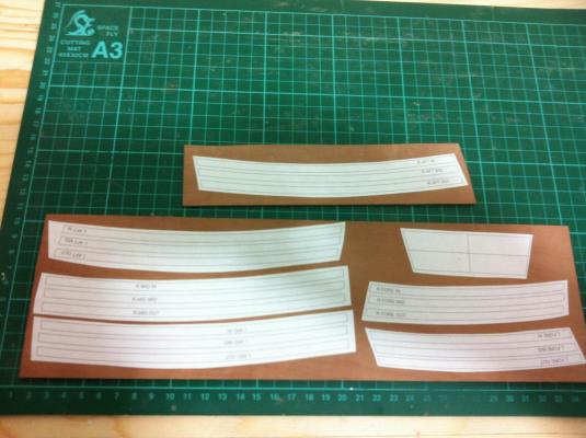
I finished the No7 frame and also finished all the planks. The curved segments were sanded with the disc sander within seconds but the concave ones were tricky. The improvised router table worked well.
Following Yambo's advise I decided on the layout of the interior. Knees, a small deck with hatches, almost identical but not quite to the boat in the internet photos. The floor, benches and deck are half ready.
I also was not happy with my transom. It made it solid instead of framed plywood but I like the original design better so I redid it and it looks good! I will cut the excess plywood ofter planking. In the last picture the Transom is secured to the jig.

Has anyone tried the beeswax approach for finishing?
- Mfelinger, Yambo, mikegerber and 3 others
-
6


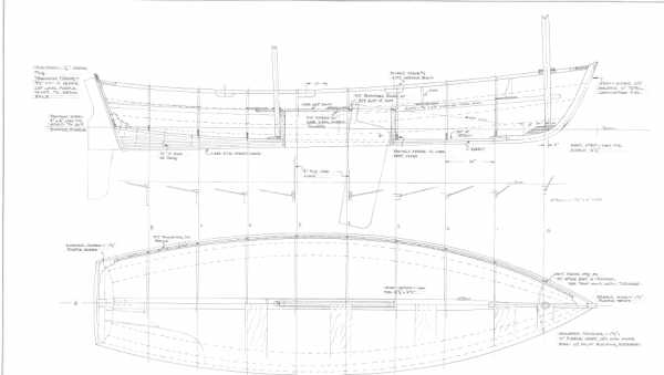
24' gaff-rigged ketch by vaddoc - FINISHED - Scale 1:12- exploration - a Tad Roberts design
in - Build logs for subjects built 1901 - Present Day
Posted · Edited by vaddoc
On a different note, I do not think there are any copyright issues from the photos I uploaded.
I think I should add the sites for reference
Tad's site
http://www.tadroberts.ca/
The american group's site
http://www.boatproject.org/#628
If there are any issues I would be grateful if the moderators would remove material appropriately